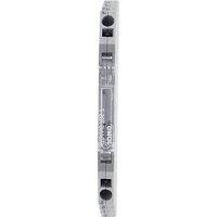
dTRANS T05 - Measurement converter Jumo - Free user manual and instructions
Find the device manual for free dTRANS T05 Jumo in PDF.


| Product type | Programmable measuring converter in 2-wire technology |
| Models | dTRANS T05 B (707050) and dTRANS T05 T (707051) |
| Dimensions (B) | Diameter 44 mm, height 33 mm (approx.) |
| Dimensions (T) | 101.2 × 102.5 × 93.1 mm (mounted on hat rail) |
| Weight (B) | Approx. 35 g |
| Weight (T) | Approx. 50 g |
| Supply voltage | 11 to 35 V DC, with reverse polarity protection |
| Input signals | Resistance probes, thermocouples, potentiometers, rheostats, DC voltage (-100 to +1100 mV) |
| Output signals (B) | 4-20 mA |
| Output signals (T) | 4-20 mA or 0-10 V |
| Linearization | Linear, linear by temperature, customer-specific (table or polynomial up to 40 points) |
| Galvanic isolation | Between input and output |
| Configuration interface | USB 2.0 (mini-B) via PC Setup software |
| Signaling LED | Two-color (red/green): green = OK, red = sensor fault, flashing = overrange |
| Operating temperature range (B) | -40 to +85 °C |
| Operating temperature range (T) | -10 to +70 °C |
| Protection degree (B) | IP54/IP65 (depending on version) |
| Protection degree (T) | IP20 |
| Housing material (B) | Polycarbonate UL 94 V2 |
| Housing material (T) | Polybutylene terephthalate UL 94 V0 |
| Electrical connection | Screw terminals (≤ 2.5 mm²) or spring terminals (depending on model) |
| Supplied accessories | Mounting material, commissioning instructions |
| Warranty and repairability | Spare parts and repair by manufacturer; configuration via PC possible |
| Maintenance and cleaning | No special maintenance; clean with a dry cloth, avoid moisture |
| Safety | Use in SELV/PELV circuits; avoid magnetic fields and electrostatic discharges |
Frequently Asked Questions - dTRANS T05 Jumo
User questions about dTRANS T05 Jumo
0 question about this device. Answer the ones you know or ask your own.
Ask a new question about this device
Download the instructions for your Measurement converter in PDF format for free! Find your manual dTRANS T05 - Jumo and take your electronic device back in hand. On this page are published all the documents necessary for the use of your device. dTRANS T05 by Jumo.
USER MANUAL dTRANS T05 Jumo
natural_image
Two views of a mechanical component: one showing a blue cylindrical housing with internal pins, the other showing two gray plastic enclosures with labeled ports (no text or symbols visible)B 707050.0
Betriebsanleitung
Operating Manual
natural_image
Two views of a mechanical component: one showing a blue cylindrical housing with internal pins, the other showing two gray plastic enclosures with labeled ports (no text or symbols visible)B 707050.0
Betriebsanleitung
1 Einleitung ....5
natural_image
Exploded view diagram of a mechanical assembly showing exploded and assembled views (no text or labels)3 Montage
3.2 Montage/Demontage des dTRANS T05 T
Montage Demontage
natural_image
Architectural floor plan outline showing room layout and structural elements (no text or labels)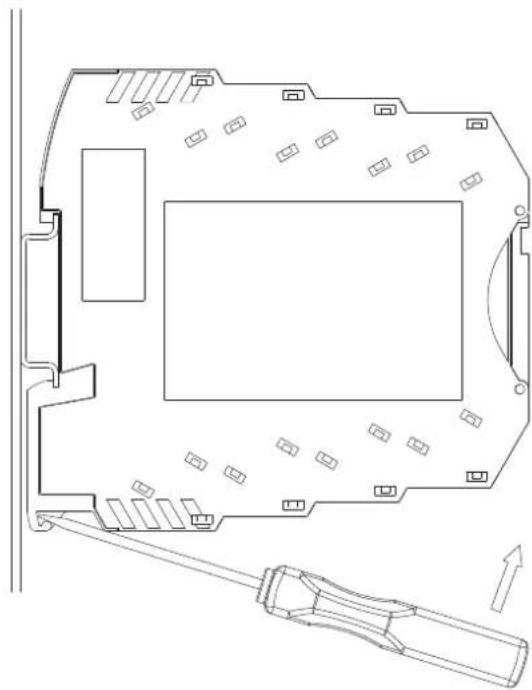
natural_image
Architectural floor plan showing room layout and mechanical component (no text or labels)natural_image
Technical line drawing of a mechanical assembly with no visible text or symbolsnatural_image
Technical line drawing of a mechanical assembly with tool and bracket (no text or symbols)natural_image
Technical line drawing of a mechanical component with a screwdriver inserted, showing internal structure and mounting holes (no text or symbols)
HINWEIS!
36039 Fulda, Germany
Telefon: +49 661 6003-727
Telefax: +49 661 6003-508
E-Mail: mail@jumo.net
Internet: www.jumo.net
36039 Fulda, Germany
Postadresse:
36035 Fulda, Germany
8712 Stäfa, Switzerland
Telefon: +41 44 928 24 44
Telefax: +41 44 928 24 48
E-Mail: info@jumo.ch
natural_image
Two views of a mechanical component: a blue cylindrical housing with internal pins and a gray multi-block assembly with labeled ports (no text or symbols visible)B 707050.0
Operating Manual
JUMO
2012-08-13/00576951
1 Introduction ....5
1.1 Safety information 5
1.2 Brief description 6
1.3 Block diagram 6
1.4 Dimensions 7
1.4.1 dTRANS T05 B (707050) transmitter 7
1.4.2 dTRANS T05 T (707051) transmitter 7
2 Identifying the device version 9
2.1 Nameplate 9
2.2 Order details 10
2.3 Scope of delivery 10
2.4 Accessories 10
3 Installation ....11
3.1 Installation of the dTRANS T05 B 11
3.2 Installation/dismounting of dTRANS T05 T 12
3.2.1 Connecting the wire to dTRANS T05 T with screw terminals 12
3.2.2 Connecting the wire to dTRANS T05 T with spring-cage terminals 13
3.2.3 Opening the hinged cover 13
3.2.4 DIN rail installation 14
4 Electrical connection .....15
4.1 Safety information 15
4.2 Terminal assignment and dimensions (mm) of dTRANS T05 B 15
4.3 Terminal assignment and dimensions (mm) of dTRANS T05 T 17
4.4 PC interface for dTRANS T05, type B and T 18
5 Configuration....19
5.1 Establishing connection between PC and transmitter 19
5.2 Setup program 20
5.3 Working with the setup program 21
5.3.1 Establishing communication with the transmitter 21
5.3.2 Customer specific linearization 23
5.3.3 Drag indicator function 24
5.3.4 Operating hours counter 25
5.3.5 Displaying the current measured value/device status 25
6 Appendix 27
6.1 Technical data 27
6.1.1 LED indication 27
Contents
6.1.2 Analog input 27
6.1.3 Measuring circuit monitoring 30
6.1.4 Output 31
6.1.5 Customer-specific linearization 31
6.1.6 Voltage supply 32
6.1.7 Environmental influences 32
6.1.8 Case 33
1.1 Safety information
General information
This manual contains information that must be observed in the interest of your own safety and to avoid damage to assets. This information is supported by symbols which are used in this manual as follows.
Please read this manual before commissioning the device. Keep the manual in a place accessible to all users at all times.
If difficulties occur during commissioning, please refrain from carrying out any manipulations that could jeopardize your warranty rights.
Warning signs

CAUTION!
This symbol in combination with the signal word indicates that damage to assets or data loss will occur if suitable precautions are not taken.
Note signs

TIP!
This symbol refers to important information about the product or its handling or additional use.
1 Introduction
1.2 Brief description
The transmitters record sensor signals from RTD temperature probes, thermocouples, resistance transmitters, or resistances/potentiometers. When using a resistance/potentiometer or RTD temperature probe, the sensor on the input side can be connected with a 2-wire, 3-wire, or 4-wire circuit. Voltage signals in the range from -100 to +1100 mV can be recorded in the same way. Depending on the selected measuring input, the linear and temperature-linear linearization variants and the possibility of easily configurable customer specific linearization are available.
Type 707050 delivers 4 to 20 mA as an output signal. Type 707051 delivers 4 to 20 mA or 0 to 10 V as an output signal. The measuring input and the output signal are electrically isolated from one another. It is possible to reverse the output signal in both types.
The transmitter configuration with respect to probe type, probe connection technology, measuring range (freely configurable), and linearization is carried out by means of a setup program on the PC. The connection to the PC is established via a USB interface which does not require additional auxiliary voltage. Via the USB interface, the min./max. process value and the min./max. operating temperature recorded by the transmitter can be read and the sensor wiring can be checked online.
The operating status of the transmitter is indicated by a two-color control LED (red/green). This is lit green during fault-free operation. A fault such as a probe break will be shown by the corresponding LED indication.
1.3 Block diagram

flowchart
graph LR
    A["Input signals: RTD temperature probe"] --> B["Transmitter"]
    C["Thermocouple"] --> B
    D["Resistor/ potentiometer"] --> B
    E["Resistance transmitter"] --> B
    F["Voltage"] --> B
    G["Supply voltage: DC 11 to 35 V"] --> B
    H["Output signals: 707050: 4 to 20 mA\n707051: 4 to 20 mA\n0 to 10 V"] --> I["USB-interface: Setup"]
    B <--> I
1.4 Dimensions
1.4.1 dTRANS T05 B (707050) transmitter
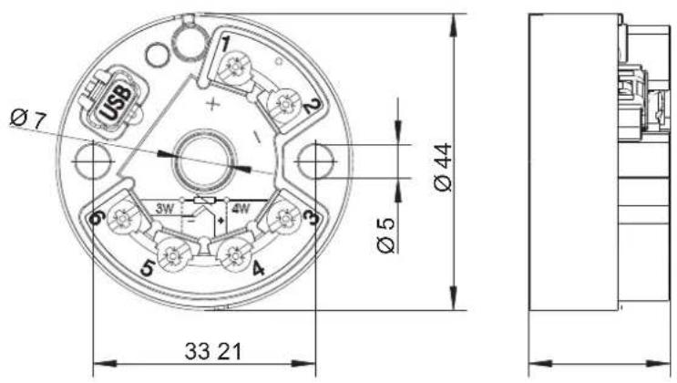
1.4.2 dTRANS T05 T (707051) transmitter
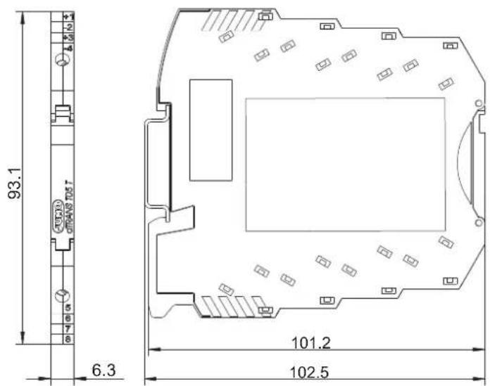
This figure shows type 707051 installed on a TH 35-7.5 DIN rail. The specifications concerning dimensions are only valid for installation on this DIN rail and change accordingly if a TH 35-15 DIN rail is used.
1 Introduction
2.1 Nameplate
| Nameplate specification Description Example | ||
| Typ Device type 707050/8-06 | ||
| TN Part no. 00582219 | ||
| F-Nr Fabrication number 0167938001012140001 | ||
 | Voltage supply DC 11 to 35 V |  |
 | Input symbol Programmable |  |
 | Output symbol 4 to 20 mA |  |
Device type (Typ)
Compare the specifications on the respective nameplate to your order documents. The supplied device version can be identified using the order details in Chapter 2.2 "Order details", page 10.
Part no. (TN)
The part no. clearly identifies an article in the catalog. It is important for communication between the customer and the sales department.
Among other things, the fabrication number indicates the production date (year/week) and the hardware version number.
Production date
Example: F-Nr = 0167938001012140001
The figures concerned are in positions 12, 13, 14, and 15 (from the left).
The device was produced in the 14th calendar week of 2012.
2 Identifying the device version
2.2 Order details
(1) Basic type
| 707050 dTRANS T05 B - 2-wire transmitter | |
| 707051 dTRANS T05 T - 2-wire transmitter in mounting rail case | |
| (2) Configuration | |
| x x | 8 Factory-set (0 to 100 °C, Pt100 3-wire circuit, 4 to 20 mA) |
| x x | 9 Customer-specific setting |
| (3) Electrical connection type | |
| x x | 06 Screw terminals |
| x 07 Spring-cage terminals | |
(1) (2) (3)

2.3 Scope of delivery
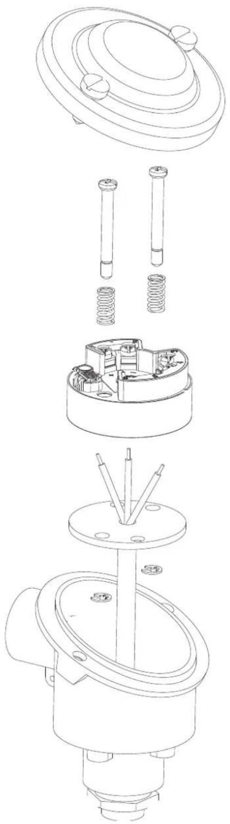
| 1 transmitter in the ordered version For type 707050: including fastening material (2 screws, 2 pressure springs, and 2 retaining washers) |
| 1 operating manual B 707050.0 |
2.4 Accessories
| Article Part no. | |
| Setup program on CD-ROM, multilingual | 00574959 |
| Operating manual B 707050.0 | 00576951 |
| USB cable, A-connector on mini B-connector, length 3 m | 00506252 |
| Screw-on end clamp for mounting rail | 00528648 |
| Mounting element for installation of type 707050 on mounting rail | 00352463 |
3.1 Installation of the dTRANS T05 B
natural_image
Exploded view diagram of a mechanical assembly showing exploded and assembled views (no text or labels)3 Installation
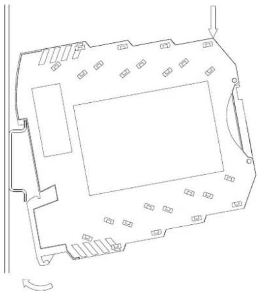
3.2 Installation/dismounting of dTRANS T05 T
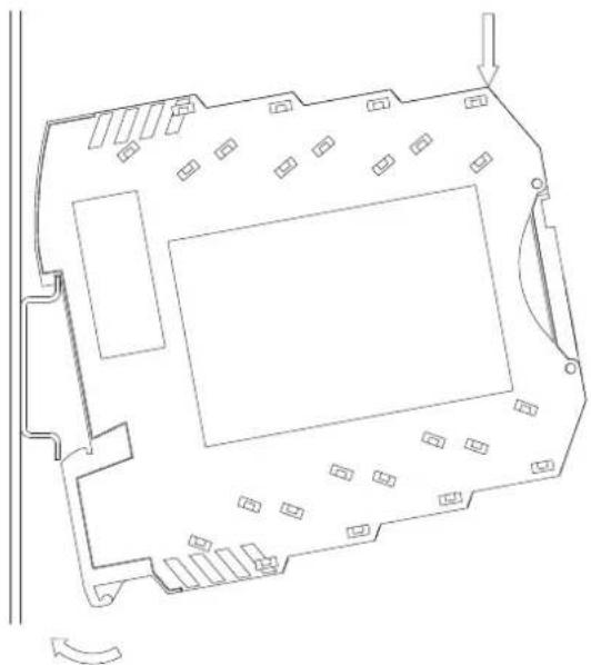
Installation Dismounting
natural_image
Architectural floor plan outline showing room layout and structural elements (no text or labels)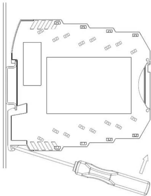
natural_image
Architectural floor plan showing room layout and mechanical component (no text or labels)3.2.1 Connecting the wire to dTRANS T05 T with screw terminals
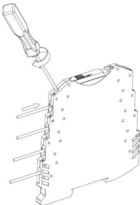
natural_image
Technical line drawing of a mechanical assembly with tool and component (no text or symbols)3.2.2 Connecting the wire to dTRANS T05 T with spring-cage terminals
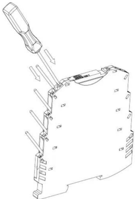
natural_image
Technical line drawing of a mechanical assembly with arrows indicating motion or force (no text or symbols)3.2.3 Opening the hinged cover
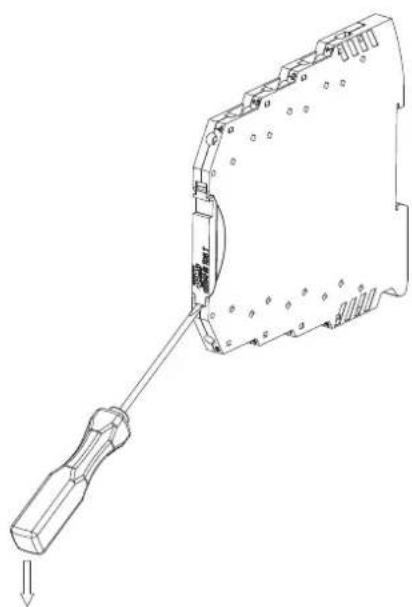
natural_image
Technical line drawing of a mechanical component with a screwdriver inserted, showing internal structure and mounting holes (no text or symbols)
TIP!
Close the hinged cover again after completing the configuration of the transmitter via the USB port.
3 Installation
3.2.4 DIN rail installation
Ensure that the device cannot slip off the DIN rail. For this purpose, attach end brackets for mounting rails alongside the outermost devices on the DIN rail. These are available as accessories.
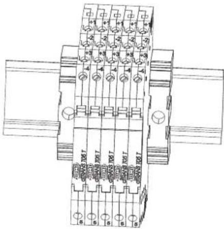
4.1 Safety information
- The electrical connection must only be carried out by qualified personnel.
- When mounting, connecting, and operating the transmitter, ensure that no electrostatic charging can take place.
- The transmitter is not suitable for installation and application areas with an explosion hazard.
- Never expose the transmitter to magnetic or electrical fields (e.g. caused by transformers, walkie-talkies, or electrostatic discharge).
- An electrical connection that deviates from the connection diagram can destroy the transmitter.
- The transmitter is suitable for use in SELV or PELV current circuits according to protection rating 3. The case implements basic insulation of up to 50V towards neighboring devices.
4.2 Terminal assignment and dimensions (mm) of dTRANS T05 B
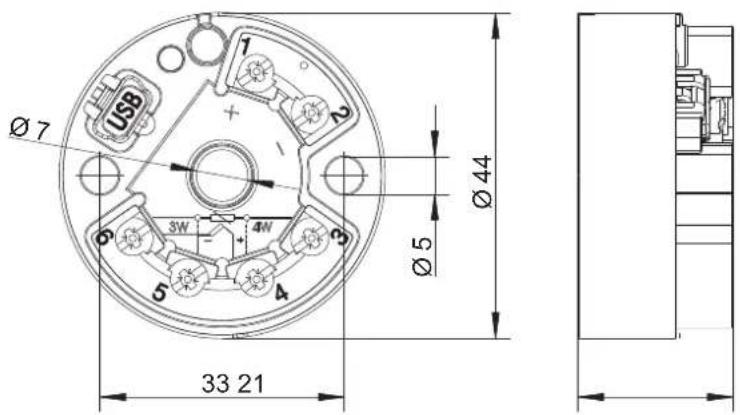
| Connection for Terminal assignment | ||
| Voltage supplyType 707050 RDC 11 to 35 V | _B = (V_b - 11 V)/22 mA | 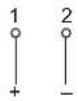 |
| Current output R4 to 20 mA V | _B = Load resistance _b = Voltage supply | |
4 Electrical connection
| Connection for Terminal assignment | ||
| Analog inputs | ||
| RTD temperature probe R2-wire circuit R | L ≤ 11 L = Lead wire resistance per wire | 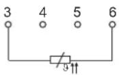 |
| RTD temperature probe R3-wire circuit (3W) R | L ≤ 11 L = Lead wire resistance per wire | 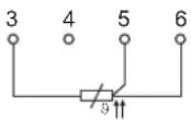 |
| RTD temperature probe R4-wire circuit (4W) R | L ≤ 11 L = Lead wire resistance per wire | 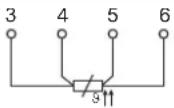 |
| Thermocouple | 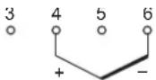 | |
| Resistance/potentiometer R2-wire circuit R | L ≤ 11 L = Lead wire resistance per wire | 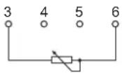 |
| Resistance/potentiometer R3-wire circuit (3W) R | L ≤ 11 L = Lead wire resistance per wire | 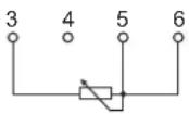 |
| Resistance/potentiometer R4-wire circuit (4W) R | L ≤ 11 L = Lead wire resistance per wire | 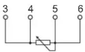 |
| Resistance transmitter E = End | S = SliderA = Start | 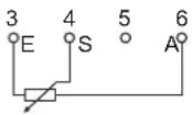 |
| Voltage 0 to 1 V | 3 4 5 6○ ○ ○ + - | |
4.3 Terminal assignment and dimensions (mm) of dTRANS T05 T
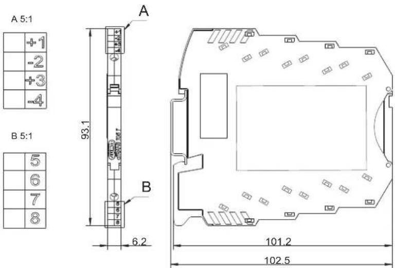
This figure shows type 707051 installed on a TH 35-7.5 DIN rail. The specifications concerning dimensions are only valid for installation on this DIN rail and change accordingly if a TH 35-15 DIN rail is used.
| Connection for Terminal assignment | ||
| Voltage supplyType 707051 RDC 11 to 35 VCurrent output R4 to 20 mA V | _B = (V _b - 11 V)/22 mA _B = Load resistance _b = Voltage supply |  |
| Voltage output0 to 10 V | 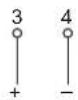 | |
| Analog inputs | ||
| RTD temperature probe R2-wire circuit R | _L ≤ 11 _L = Lead wire resistance per wire | 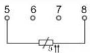 |
| RTD temperature probe R3-wire circuit (3W) R | _L ≤ 11 _L = Lead wire resistance per wire | 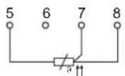 |
| RTD temperature probe R4-wire circuit (4W) R | _L ≤ 11 _L = Lead wire resistance per wire | 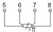 |
4 Electrical connection
| Connection for Terminal assignment | ||
| Thermocouple | 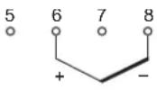 | |
| Resistance/potentiometer R2-wire circuit R | _L ≤ 11 _L = Lead wire resistance per wire | 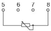 |
| Resistance/potentiometer R3-wire circuit (3W) R | _L ≤ 11 _L = Lead wire resistance per wire | 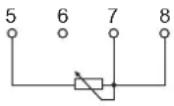 |
| Resistance/potentiometer R4-wire circuit (4W) R | _L ≤ 11 _L = Lead wire resistance per wire | 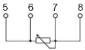 |
| Resistance transmitter E = End | S = SliderA = Start | 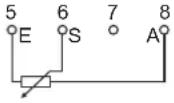 |
| Voltage to 1 V | 5 6 7 8○ ○ ○ ○+ - |
4.4 PC interface for dTRANS T05, type B and T
| Connection for Type Terminal assignment | |||
| USB connection to the PC | USB interface 2.0 (Mini-B; Full-Speed) | Standard (5-pin) |  |
5.1 Establishing connection between PC and transmitter
The connection between transmitter and PC is established via a USB cable.
Connection between PC and transmitter, using the example of type 707050
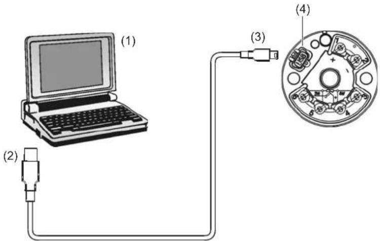
(1) Laptop/PC (3) Mini USB plug type B
(2) USB plug (4) USB socket for USB plug type B
For setup via USB, establish the following connections:
| Step Activity |
| 1 Insert the USB plug (2) of the USB cable into the laptop/PC (1). |
| 2 Insert the mini USB plug (3) of the USB cable into the transmitter socket (4). |

TIP!
If the connection between the PC and the transmitter is established via USB and the transmitter is not wired on the output side, the energy is supplied to the transmitter via the USB interface of the PC. The current output (and the voltage output for dTRANS T05 T) and the two-color LED are then not in operation.
When the transmitter is operated without a USB connection, the USB interface is deactivated.

TIP!
To guarantee smooth operation of the transmitter via a USB interface it must correspond to USB specification 2.0.

CAUTION!
Do not connect the USB with a grounded sensor, even if the ground of the PC is grounded (e.g. a desktop PC). The measuring input and the USB interface are not electrically isolated.

CAUTION!
Avoid a short circuit between the USB ground and the sensor terminals.
5 Configuration
5.2 Setup program
The transmitter is configured on the PC with the setup program. The connection between transmitter and PC is established via a USB cable. The transmitter interface is a USB port of the Mini-B type. It supports standard 2.0 "Full Speed". Once configuration of the transmitter has been completed make sure that the attached hinged-on lid is back on the transmitter's USB interface.
![JUMO dTRANS T05 (Unicode) - [Setup1] File Edit Data transfer Extras Window Info JUMO dTRANS T05 Setup File info header Configuration Hardware Analog input Analog output Customized linearization Extended information File info text ► File info header: ► Hardware: ► Analog input: ► Analog output: ► Customized linearization: ► Extended information: ► File info text: Setup1 Date Time Name Value 1 Version data Process data Unit data MUX data /](/content/2026/04/732940/images/ad4193659f0c8d21f7f2e6d02e0c2cc5901fcc5169161607f7327d0f17e5e35e.jpg)
Configurable parameters
| Sensor type | |
| Connection type 2/3-wire circuit or 4-wire circuit for RTD temperature probes or resistors/potentiometers | |
| Linearization | |
| Customer-specific linearization | |
| Sensor factor for thermocouple/RTD temperature probe | |
| Lead wire resistance with 2-wire circuit | |
| External or internal cold junction for thermocouple | |
| Scaling | |
| Digital filter | |
| Offset | |
| Unit | |
| Behavior in the event of a probe break/short-circuit | |
| Output signal increasing or decreasing (reversion) | |
| Output functions, current 4 to 20 mAType 705050 and type 705051 | 4 to 20 mA scalable (start/end)Constant current source |
| Output functions, voltage 0 to 10 VOnly type 705051 | 0 to 10 V scalable (start/end)Constant voltage source |
| TAG number (10-digit) and description (20-digit) |
| Installation date |
| Data pertaining to version, process and device of the transmitter can be displayed |
Hardware and software requirements
For operation and the installation of the setup program the following hardware and software requirements have to be met.
| Microsoft ^a Windows ^a XP, Windows Vista ^a , Windows 7 32-bit/64-bit |
| 1 GB RAM |
| 200 MB free hard disk space |
| 1 USB interface |
^a Microsoft, Windows, and Windows Vista are registered trademarks of Microsoft Corporation.
5.3 Working with the setup program
5.3.1 Establishing communication with the transmitter
The correct transmitter type must be selected in the setup program in order to use the setup program to transfer a configuration to the transmitter or to establish the connection so that device data can be queried.
Device wizard with automatic detection of connected hardware
| Step Activity | |
| 1 Connect the transmitter with the USB cable. | |
| 2 Start the setup program. | |
| 3 In the navigation window, double-click S ETUP > CONFIGURATION > HARDWARE. | |
| 4 In the device wizard, select A UTOMATIC DETECTION and click NEXT. | |
| 5 Once the correct type is displayed, click F INISH. | |
| 6 The transmitter is connected. |
Device and process data can be displayed and data transfer is possible. This can be performed via the menu DATA TRANSFER > DATA TRANSFER TO DEVICE... or DATA TRANSFER FROM DEVICE... or the corresponding buttons.
Device wizard with custom setting
| Step Activity | |
| 1 Connect the transmitter with the USB cable. | |
| 2 Start the setup program. | |
| 3 In the navigation window, double-click SETUP > CONFIGURATION > HARDWARE. | |
| 4 In the device wizard, select USER-DEFINED SETTING and click NEXT. |
5 Configuration
| Step Activity | |
| 5 | Select the correct transmitter type and click NEXT. |
| 6 Once the correct type is displayed, click F INISH. | |
| 7 The transmitter is connected. | |
Device and process data can be displayed and data transfer is possible. This can be performed via the menu DATA TRANSFER > DATA TRANSFER TO DEVICE... or DATA TRANSFER FROM DEVICE... or the corresponding buttons.
Saving/using an existing configuration
Once the configuration of a transmitter has been completed, the configuration can be saved under FILE > SAVE AS .... All configured parameters and settings are saved in this setup file. These can be accessed and changed at any time, even if no device is connected.
| Step Activity | |
| 1 | Start the setup program. The setup that was opened most recently will be opened again. Close it if required. |
| 2 Select a setup file under F ILE > OPEN and confirm with OPEN. The file is loaded. | |
| 3 The configuration can also be performed without a transmitter being connected. | |
| 4 To load | or read the configuration on a transmitter, the transmitter must be connected and the connection must be established via the device manager or under DATA TRANSFER > ESTABLISH CONNECTION. |
Device and process data can be displayed and data transfer is possible. This can be performed via the menu DATA TRANSFER > DATA TRANSFER TO DEVICE... or DATA TRANSFER FROM DEVICE... or the corresponding buttons.
5.3.2 Customer specific linearization
The dTRANS T05 B and T transmitters provide the option of customer specific linearization of measured values. The corresponding configuration screen can be accessed in the setup program via the EDIT > CUSTOMIZED LINEARIZATION menu or in the tree structure under SETUP > CONFIGURATION > CUSTOMIZED LINEARIZATION. Linearization is performed via a table of values or a 4th order polynomial.
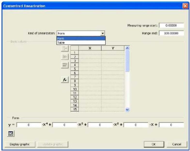
Linearization on the basis of the 4th order polynomial
For linearization on the basis of the 4th order polynomial, the FORMULA entry must be selected in the KIND OF LINEARIZATION selection field. The coefficients of the polynomial can be entered directly and the table is locked to entries. The graphic display is enabled by clicking the DISPLAY GRAPHIC button.
Linearization on the basis of the table of values
If the linearization is to be performed using a table with value pairs, the TABLE entry must be selected in the KIND OF LINEARIZATION selection field. It is not possible to enter polynomial coefficients. The X and Y values can then be entered in the table and displayed by clicking the DISPLAY GRAPHIC button.
Linearization with calculated polynomial coefficients
If at least two value pairs are used for linearization, the setup program provides the option for calculating the polynomial coefficients from these values. The linearization is then performed on the basis of the polynomial. For this purpose, the TABLE entry must be selected in the selection field. If the respective value pairs are entered, the polynomial coefficients can be calculated automatically by clicking the f_x button. The graphic display is enabled by clicking the DISPLAY GRAPHIC button. The following figures show the example of a table with value pairs and the graph of the value pairs with a superimposed graph of the polynomial.
5 Configuration
| X | Y | |
| 1 | -0.1 | -120 |
| 2 | -0.069231 | -118.2529 |
| 3 | -0.038462 | -113.0647 |
| 4 | 0.007632 | -104.5929 |
| 5 | 0.023077 | -93.09511 |
| 6 | 0.053846 | -78.92058 |
| 7 | 0.084615 | -62.5 |
| 8 | 0.115385 | -44.33232 |
| 9 | 0.146154 | -24.96954 |
| 10 | 0.175923 | -5 |
| 11 | 0.207632 | 14.96954 |
| 12 | 0.238462 | 34.33232 |
| 13 | 0.269231 | 52.5 |
| 14 | 0.32 | 68.92058 |
| 15 | 0.330759 | 83.09511 |
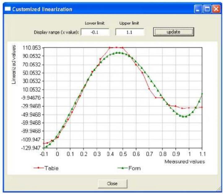
line
| Measured values | Table | Form | | --------------- | ----------- | ----------- | | -0.1 | -129.947 | -129.947 | | 0.0 | -109.947 | -109.947 | | 0.1 | -89.9468 | -89.9468 | | 0.2 | -79.9468 | -79.9468 | | 0.3 | -69.9468 | -69.9468 | | 0.4 | -59.9468 | -59.9468 | | 0.5 | -49.9468 | -49.9468 | | 0.6 | -39.9468 | -39.9468 | | 0.7 | -29.9468 | -29.9468 | | 0.8 | -19.9468 | -19.9468 | | 0.9 | -5.042 | -5.042 | | 1.0 | 5.042 | 5.042 | | 1.1 | 15.042 | 15.042 |5.3.3 Drag indicator function
The drag indicator function records the minimum and maximum process variables (e.g. temperature) that appeared on the sensor during transmitter operation. These values can be reset. The reset times for the drag indicator are saved in the device and are also displayed. In addition to the actual minimum and maximum process values, the time at which the respective variables occurred will be displayed – measured in operating hours since the reset time. This enables conclusions to be drawn with regard to special features of the plant.
To view this data, the ONLINE DATA checkbox in the WINDOW menu must be selected in the setup program and the PROCESS DATA tab must be selected at the bottom of the setup program window.
| Date | Time | Name | Value | |
| 1 | 8/7/2012 | 7:47:37 AM | Input | 111.04 Ohm |
| 2 | 8/7/2012 | 7:47:37 AM | Input (linearized) | 28.382 °C / 83.088 °F |
| 3 | 8/7/2012 | 7:47:37 AM | Output | 21.760 mA |
| 4 | 8/7/2012 | 7:47:37 AM | Type | JUMO dTRANS T05 Type B |
| 5 | 8/7/2012 | 7:47:37 AM | Device status | Test mode |
| 6 | 8/7/2012 | 7:47:37 AM | Reset time of the minimum process variables (Slave pointer) | 19.06.2012 - 08:21 |
| 7 | 8/7/2012 | 7:47:37 AM | Minimum process variables Time of occurrence (in working hours after reset) | 36 °C / 96.8 °F 26 h |
| 8 | 8/7/2012 | 7:47:37 AM | Reset time of the maximum process variables (Slave pointer) | 19.06.2012 - 08:21 |
| 9 | 8/7/2012 | 7:47:37 AM | Maximum process variables Time of occurrence (in working hours after reset) | 244.2 °C / 471.6 °F 0 h |
| 10 | 8/7/2012 | 7:47:37 AM | Temperature in the case | 21.6 °C / 70.8 °F |
The drag indicator can be reset via the menu item EXTRAS > RESET DRAG INDICATOR.
Example
In the figure above, the reset time of the minimum process variable is on June 19, 2012 at 08:21 a.m. Should you wish to establish the time at which the minimum process variable occurred, the value must be read in the corresponding line. In the example, this was 36.0 °C and occurred 26 hours after the reset time. According to the example, the minimum process variable occurred on June 20, 2012 at 10:21 a.m.
5.3.4 Operating hours counter
The minimum and maximum device temperature, operating hours in various ambient temperature ranges, and overall operating hours can be viewed using the operating hours counter function. To display this data, the ONLINE DATA checkbox in the WINDOW menu must be selected in the setup program and the DEVICE DATA tab must be selected at the bottom of the setup program window.
| × | Date | Time | Name | Value |
| 1 | 8/7/2012 | 11:52:43 AM | min. device temperature | -22.0 °C / -7.5 °F |
| 2 | 8/7/2012 | 11:52:43 AM | max. device temperature | 89.0 °C / 192.2 °F |
| 3 | 8/7/2012 | 11:52:43 AM | Operating hour counter (total) | 124 h |
| 4 | 8/7/2012 | 11:52:43 AM | Operating hour counter (after configuration) | 17 h |
| 5 | 8/7/2012 | 11:52:43 AM | Operating hour counter (-40 ... 0°C) | 41 h |
| 6 | 8/7/2012 | 11:52:43 AM | Operating hour counter (0 ... 50°C) | 55 h |
| 7 | 8/7/2012 | 11:52:43 AM | Operating hour counter (50 ... 85°C) | 22 h |
| 8 | 8/7/2012 | 11:52:43 AM | Operating hour counter (> 85°C) | 6 h |
The operating hours counter (according to the configuration) can be called up and reset via the EXTRAS > OPERATING HOURS COUNTER menu item. No other operating hours counters can be reset.

TIP! The calculated min./max. time is derived with hourly resolution from the reset time of the drag indicator.
5.3.5 Displaying the current measured value/device status
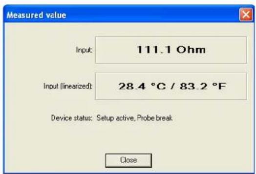
In the setup program, the current input value and the linearized value can be displayed using the "Display measured value" function. The current device status is also displayed. Values that are out of range and wiring problems are displayed in text form. The function can be accessed by clicking the button with the magnifying glass symbol or in the menu under EXTRAS > DISPLAY MEASURED VALUE.
5 Configuration
6.1 Technical data
6.1.1 LED indication
| Display Example Meaning | ||
| The two-color LED is continually lit green |  | OK |
| The two-color LED is continually lit red |  | Sensor error |
| The two-color LED alternately flashes red/green |  | Out of range |
| The two-color LED is continually lit red and green simultaneously |  | Initialization phase, Test mode "Permanent Current Output" mode |
6.1.2 Analog input
All analog inputs are equipped with a digital filter of second order (filter constant adjustable from 0 to 10 s) and have a sampling rate of >2 measurements per second.
RTD temperature probe
| Designation Standard ITS Connection | type | Measuring range in °CMin. Max. | Measuring accuracya | |||
| Pt100 IEC 60751:2008 ITS-90 Pt500 2/3-wire -200 850 ±0.4 K Pt1000 TK=3.85 × 10⁻³¹/K | 2/3-wire -100 200 ±0.2 K | |||||
| 4-wire | -100 200 | ±0.1 K | ||||
| 4-wire | -200 850 | ±0.2 K | ||||
| Pt100 TK=3.917 × 10⁻³¹/K | GOST 6651-2009 A.2 | ITS-90 | 2/3-wire -100 | 200 ±0.2 K | ||
| 2/3-wire | -200 | 850 | ±0.4 K | |||
| 4-wire | -100 | 200 ±0.15 K | ||||
| 4-wire | -200 | 850 ±0.25 K | ||||
| Pt50 TK=3.91 × 10⁻³¹/K | 2/3-wire -200 | 850 ±0.5 K | ||||
| 4-wire | -200 | 850 | ±0.3 K | |||
| Ni100 DIN 43760 IPTS-TK=6.18 × 10⁻³¹/K | IPTS-4 K | 68 | 2/3-wire -60 | 250 ±0.4 K | ||
| 4-wire | -60 | 250 | ±0.2 K | |||
| Ni500 2/3-wire -60 250 ±0.4 KTK=6.18 × 10⁻³¹/K | ||||||
| 4-wire | -60 | 250 | ±0.2 K | |||
| Ni1000 TK=6.18 × 10⁻³¹/K | 2/3-wire -60 | 250 ±0.4 K | ||||
| 4-wire | -60 | 250 | ±0.2 K | |||
6 Appendix
| Designation Standard ITS Connection | type | Measuring range in °CMin. Max. | Measuring accuracya | |||
| Ni 100 GOST 6651-TK=6.17×1301/K 4-wire -60 | 2009 A.5180 ±0.2 K | ITS-90 | 2/3-wire -60 180 | ±0.4 K | ||
| Cu50 GOST 6651-TK=4.28×1301/K 4-wire -180 | 2009 A.3200 ±0.3 K | ITS-90 | 2/3-wire -180 200 | ±0.5 K | ||
| Cu100 2/3-wire -180 200 ±0.4 KTK=4.28×10⁻³¹/K 4-wire -180 | 200 ±0.2 K | |||||
^a The accuracy value refers to the complete measuring range.
| Connection type | 2-wire, 3-wire, or 4-wire circuit |
| Sensor lead resistance- For 3/4-wire circuit- For 2-wire circuit | ≤ 11 Ω per line |
| Measuring resistance + ≤ 22 Ω inner line resistance | |
| Sensor current | < 0.3 mA |
Thermocouples
| Designation Type Standard ITS Measuring | range in °CMin. Max. | Measuring accu-racya | ||||
| Pt13Rh-Pt | R | IEC 584-1 | ITS-90 | -50 | 1768 | ± 0.15 % from +50 °C |
| Pt10Rh-Pt | S | IEC 584-1 | ITS-90 | -50 | 1768 | ± 0.15 % from +20 °C |
| Pt30Rh-Pt6Rh | B | IEC 584-1 | ITS-90 | 0 | 1820 | ± 0.15 % from +400 °C |
| Fe-CuNi | J | IEC 584-1 | ITS-90 | -210 | 1200 | ± 0.1 % from -100 °C |
| Cu-CuNi | T | IEC 584-1 | ITS-90 | -270 | 400 | ± 0.1 % from -150 °C |
| NiCr-CuNi | E | IEC 584-1 | ITS-90 | -270 | 1000 | ± 0.1 % from -80 °C |
| NiCr-Ni | K | IEC 584-1 | ITS-90 | -270 | 1372 | ± 0.1 % from -80 °C |
| NiCrSi-NiSi | N | IEC 584-1 | ITS-90 | -270 | 1300 | ± 0.1 % from -80 °C |
| Fe-CuNi | L | DIN 43710 | IPTS-68 | -200 | 900 | ± 0.1 % |
| Cu-CuNi | U DIN | 43710 IPTS-68 | -200 | 600 | ± 0.1 % from -100 °C | |
| Chromel-Copel (Ni9.5Cr-Cu44Ni) | L | GOST R 8.585-2001 | ITS-90 | -200 | 800 | ± 0.1 % from -80 °C |
| Chromel-Alumel | GOST R 8.585-2001 | ITS-90 | -270 | 1372 | ± 0.1 % from -80 °C | |
| W5Re-W20Re | A1 | GOST R 8.585-2001 | ITS-90 | 0 | 2500 | ± 0.15 % |
| W5Re-W26Re | C | ASTM E230/E230M-11 | ITS-90 | 0 | 2315 | ± 0.15 % |
| W3Re-W25Re D ASTM E1 | 751/E1 | 751M-09 | ITS-90 0 | 2315 ± 0.25 % | ||
| PL II (PlatinelbII) | ASTM E1751/E1751M-09 | ITS-90 0 | 1395 ± 0.15 % | |||
| Cold junction | Pt1000 internal or external cold junction; temperature adjustable 0 to 80 °C |
| Cold junction accuracy | ± 1 K |
^a The accuracy values refer to the complete measuring range.
b Platinel is a registered trademark of Engelhardt Corp.
Resistance transmitter and resistor/potentiometer
| Designation Measuring range | Measuring accuracy | |
| Resistance transmitter | Up to 10000 Ω | ±10 Ω |
| Resistor/potentiometer | ≤400 Ω | ±400 mΩ |
| ≥400 Ω to ≤4000 Ω | ±4 Ω | |
| >4000 Ω to ≤10000 Ω | ±10 Ω | |
6 Appendix
| Designation Measuring range | Measuring accuracy | |
| Connection type Resistance transmitter: 3-wire circuit(A = Start, S = Slider, E = End)Resistor/potentiometer: 2-wire circuit, 3-wire circuit, and 4-wire circuit | ||
| Sensor lead resistance | ≤ 11 per line for 2-wire circuit, 3-wire circuit, and 4-wire circuit | |
Direct current
| Designation Measuring range | Accuracy | a | Input resistance |
| Input for mV generator | -100 to 1100 mV | ±0.05 % | R_E ≥ 1 M |
^a The accuracy value refers to the complete measuring range.
6.1.3 Measuring circuit monitoring
| Type 707050 Type 707051 | ||
| Underrange Linear drop up to 3 | .8 mA Linear drop up to 3 (According to NAMUR recommendation 43) | .8 mA (According to NAMUR recommendation 43) Linear drop up to -0.12 V |
| Overrange | Linear increase up to 20.5 mA (According to NAMUR recommendation 43) | Linear increase up to 20.5 mA (According to NAMUR recommendation 43) Linear increase up to 10.31 V |
| Probe short-circuit/probe and cable break | RTD temperature probe: (configurable) ≤ 3.6 mA, ≥ 21.7 mA Or free setting: 3.6 mA to 23 mA | RTD temperature probe: (configurable) ≤ 3.6 mA, ≥ 21.7 mA Or free setting: 3.6 mA to 23 mA |
| ≤ -0.2 V, ≥ 11.0 V Or free setting: -0.25 V to 11.875 V | ||
| Thermocouple: (configurable)a ≤ 3.6 mA, ≥ 21.7 mA Or free setting: 3.6 mA to 23 mA | Thermocouple: (configurable)a ≤ 3.6 mA, ≥ 21.7 mA Or free setting: 3.6 mA to 23 mA | |
| ≤ -0.2 V or ≥ 11.0 V Or free setting: -0.25 V to 11.875 V | ||
| Current limiting in the event of a probe short circuit or probe break | ≤ 23 mA | |
^a For thermocouples and mV generator a probe short-circuit detection is not possible.
6.1.4 Output
| Type 707050 Type 707051 | ||
| Output signal Load-independent | direct current: Load-independent direct current: Free setting: 4 to 20 mA or 20 | current: to 4 mA Free setting: 4 to 20 mA or 2 |
| Voltage signal: Free setting: 0 to 10 V or 10 to 0 V | ||
| Electrical isolation Between input test voltage | put and output: Between input and output: = 3.75 kV/50 Hz | = 1.875 kV/50 Hz |
| Transmission behavior Linear, temperature-linear | ||
| Customer specificReversion of the output signal | ||
| Step response 0 to 100 % | < 2 s (with filter constant 0 s) | |
| Switch-on delay | 5 s (correct measured value after the supply voltage is applied) | |
| Current output | ||
| Load ( R_b ) | R_b = (U_b - 11 V)/0.022 A | |
| Load error | ≤ ±0.02 %/100 Ω | |
| Calibration conditions/accuracy | DC 24 V at approx. 22 °C/±0.05 %a | |
| Voltage output | ||
| Load resistance | ≥ 2 kΩ | |
| Load influence | ± 15 mV | |
| Residual ripple | ± 1 % referring to 10 V, 0 to 90 kHz | |
| Calibration conditions/accuracy | DC 24 V at approx. 22 °C/±0.05 %b | |
^a All specifications refer to the measuring range end value of 20 mA
^b All specifications refer to the measuring range end value of 10 V
6.1.5 Customer-specific linearization
| Method | Characteristics |
| Pairs of values | Max. number: 40 |
| Interpolation: linear | |
| Formula | Number of coefficients: 5 |
| Polynomial: 4th order |
6.1.6 Voltage supply
| 707050 707051 | ||
| Voltage supply (Ub) DC 11 to 35 V (with reverse voltage protection a)Only for operation in SELV, PELV current circuits according to DIN EN 50178 | ||
| Voltage supply error | ≤ ± 0.01 %/V deviation from 24 Vb | |
^a Prerequisite for use of the voltage output of type 707051 is a supply voltage of at least 15 V
^b All specifications refer to the measuring range end value of 20 mA
6.1.7 Environmental influences
^a All specifications refer to the measuring range end value of 20 mA or 10 V
^b Under calibration conditions
^c % refer to the set measuring span. The greater value of the long-term stability applies.
| 707050 707051 | ||
| Operating temperature range | -40 to +85 °C | -10 to +70 °C |
| Storage temperature range | -40 to +100 °C | -10 to +70 °C |
| Temperature influenceRTD temperature probeResistance transmitterResistor/potentiometerThermocoupleDirect current | ≤ ±0.005 %/K deviation from 22 °Ca≤ ±0.01 %/K deviation from 22 °Ca≤ ±0.01 %/K deviation from 22 °Ca≤ ±0.005 %/K deviation from 22 °Ca (plus accuracy of the cold junction)≤ ±0.01 %/K deviation from 22 °Ca | |
| Long-term stability | ≤ 0.1 K/yearbor ≤ 0.05%/year | |
| Resistance to climatic conditionsIn terminal head, form BOpen assemblyOn DIN rail | Rel. humidity ≤ 95 %, with condensationRel. humidity ≤ 95 %, without condensation | Rel. humidity ≤ 95 %, without condensation |
| Vibration resistanceDIN EN 60068-2-6DIN EN 60068-2-27Germanischer Lloyd | Max. 2 g at 10 to 2000 HzShock; 10 g/6 msCharacteristic line 2 | Max. 2 g at 10 to 55 HzShock; 10 g/6 ms- |
| Electromagnetic compatibility (EMC)Interference emissionInterference resistance | According to DIN EN 61326-1Class BIndustrial requirements | |
| IP protection typeIn terminal head, form B IP54/IP65 (depending on the version)Open assembly IP00On DIN rail IP20 | ||
6.1.8 Case
| 707050 707051 | ||
| Material | Polycarbonate UL 94 V2 (grouted) | Polybutylene terephthalate UL 94 V0 |
| Terminal type Screw terminals: Wire type Rigid and flexible wires | Screw terminals: Rigid and flexible wires ≤ 1.75 mm2; Max. torque 0.6 Nm | 0.2 AWG/kcmil min. 26, max 12 Stripping length 12 mm Torque 0.5 - 0.6 Nm |
| Spring-cage terminals Rigid and flexible wires 0.2 mm2 to 2.5 mm2 AWG/kcmil min. 26, max 12 Stripping length 8 mm | ||
| Assembly type | In terminal head, form B (DIN EN 50446); In the surface-mounted case (see accessories); In the control cabinet (mounting element required) | On DIN rail TH 35-7.5 Or TH 35-15 (DIN EN 60715); |
| Installation position | Any | |
| Weight | ~ 35 g | ~ 50 g |
6 Appendix

JUMO GmbH & Co. KG
Street address:
36039 Fulda, Germany
Delivery address:
Mackenrodtstraße 14
36039 Fulda, Germany
Postal address:
36035 Fulda, Germany
Phone: +49 661 6003-0
Fax: +49 661 6003-607
E-mail: mail@jumo.net
Internet: www.jumo.net
JUMO Instrument Co. Ltd.
JUMO House
Temple Bank, Riverway
Harlow - Essex CM20 2DY, UK
Phone: +44 1279 63 55 33
Fax: +44 1279 63 52 62
E-mail: sales@jumo.co.uk
Internet: www.jumo.co.uk
JUMO Process Control, Inc.
8 Technology Boulevard
Canastota, NY 13032, USA
Phone: 315-697-5866
1-800-554-JUMO
Fax: 315-697-5867
E-mail: info.us@jumo.net
Internet: www.jumousa.com
JUMO dTRANS T05
natural_image
Two views of a mechanical component: one showing a blue cylindrical housing with internal pins, the other showing two gray plastic enclosures with labeled ports (no text or symbols visible)B 707050.0
natural_image
Exploded view diagram of a mechanical assembly showing exploded and assembled views (no text or labels)3 Montage
natural_image
Architectural floor plan outline showing room layout and structural elements (no text or labels)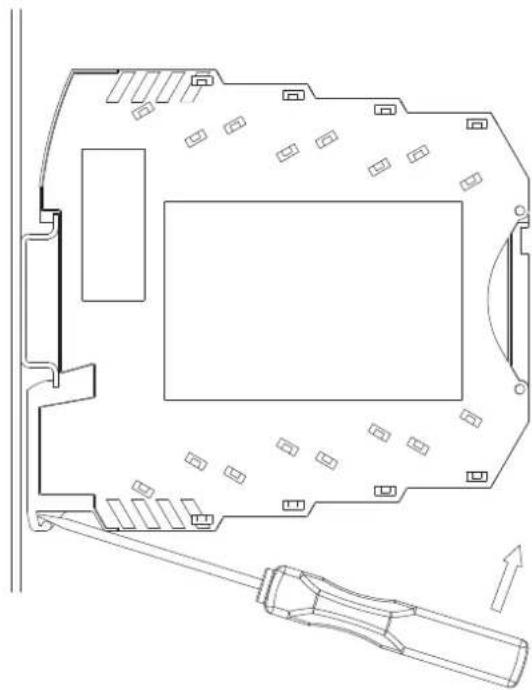
natural_image
Architectural floor plan showing room layout and mechanical component (no text or labels)natural_image
Technical line drawing of a mechanical assembly with tool and component (no text or symbols)natural_image
Technical line drawing of a mechanical assembly with tool and component annotations (no text or symbols)natural_image
Technical line drawing of a mechanical component with a screwdriver inserted, showing internal structure and mounting holes (no text or symbols)
REMARQUE!
natural_image
Pure technical line drawing of a mechanical assembly without any text, numbers, or symbols| Raccordement pour Brochage | ||
| AlimentationType 707050 R11 - 35 V DCSortie en courant R4 - 20 m A | _B = (U_b - 1 1 V) / 2 2 mA _B = résistance de charge = alimentation |  |
8712 Stäfa, Switzerland
Telefon: +41 44 928 24 44
Telefax: +41 44 928 24 48
E-Mail: info@jumo.ch

- Einleitung ....5
- Montage
- Montage/Demontage des dTRANS T05 T
- HINWEIS!
- Introduction ....5
- Identifying the device version 9
- Installation ....11
- Electrical connection .....15
- Configuration....19
- Appendix 27
- Contents
- Safety information
- General information
- Warning signs
- CAUTION!
- Note signs
- TIP!
- Introduction
- Brief description
- Block diagram
- Dimensions
- dTRANS T05 B (707050) transmitter
- dTRANS T05 T (707051) transmitter
- Nameplate
- Device type (Typ)
- Part no. (TN)
- Production date
- Identifying the device version
- Order details
- Scope of delivery
- Accessories
- Installation of the dTRANS T05 B
- Installation
- Installation/dismounting of dTRANS T05 T
- Connecting the wire to dTRANS T05 T with screw terminals
- Connecting the wire to dTRANS T05 T with spring-cage terminals
- Opening the hinged cover
- DIN rail installation
- Safety information
- Terminal assignment and dimensions (mm) of dTRANS T05 B
- Electrical connection
- Terminal assignment and dimensions (mm) of dTRANS T05 T
- PC interface for dTRANS T05, type B and T
- Establishing connection between PC and transmitter
- Configuration
- Setup program
- Configurable parameters
- Hardware and software requirements
- Working with the setup program
- Establishing communication with the transmitter
- Device wizard with automatic detection of connected hardware
- Device wizard with custom setting
- Saving/using an existing configuration
- Customer specific linearization
- Linearization on the basis of the 4th order polynomial
- Linearization on the basis of the table of values
- Linearization with calculated polynomial coefficients
- Drag indicator function
- Example
- Operating hours counter
- Displaying the current measured value/device status
- Technical data
- LED indication
- Analog input
- Appendix
- Measuring circuit monitoring
- Output
- Customer-specific linearization
- Voltage supply
- Environmental influences
- Case
- JUMO GmbH & Co. KG
- JUMO Instrument Co. Ltd.
- JUMO Process Control, Inc.
- JUMO dTRANS T05
- REMARQUE!
Brand : Jumo
Model : dTRANS T05
Category : Measurement converter