
A9Z61263 - Circuit breakers SCHNEIDER - Free user manual and instructions
Find the device manual for free A9Z61263 SCHNEIDER in PDF.

| Product type | Residual current circuit breaker (RCCB) |
| Brand | Schneider Electric |
| Model | A9Z61263 |
| Category | Circuit breakers |
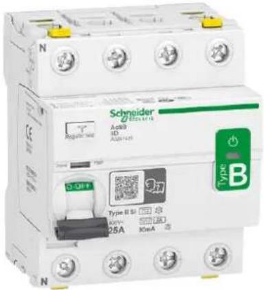
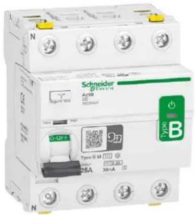
| Series | Acti9 iID |
| Type | B-SI (Super Immune) |
| Number of poles | 2P, 3P, 4P (depending on reference) |
| Rated voltage (Ue) | 230/400 V AC |
| Rated current (In) | 25 A |
| Residual current (IΔn) | 30 mA |
| Rated impulse withstand voltage (Uimp) | 6 kV |
| Insulation voltage (Ui) | 250 V (2P) / 500 V (4P) |
| Width (modules) | 4 modules (per pole) |
| Operating temperature | -25°C to +60°C |
| Standards | IEC 61008-2, IEC 62423 |
| Test function | T button (monthly test recommended) |
| Voltage presence indicator | Green LED |
| Housing material | Self-extinguishing plastic |
| Maintenance | Monthly test; clean with dry cloth |
Frequently Asked Questions - A9Z61263 SCHNEIDER
User questions about A9Z61263 SCHNEIDER
0 question about this device. Answer the ones you know or ask your own.
Ask a new question about this device
Download the instructions for your Circuit breakers in PDF format for free! Find your manual A9Z61263 - SCHNEIDER and take your electronic device back in hand. On this page are published all the documents necessary for the use of your device. A9Z61263 by SCHNEIDER.
USER MANUAL A9Z61263 SCHNEIDER
Residual Current Device iID (Type B) SI User Guide and FAQs
The Acti9 iID B-SI Type - User Guide is available in the below mentioned languages:

English

Svenska

Italiano

Français

Dansk

Español

Deutsch

中文,汉语,漢語

Norsk

Nederlands
User Guide 4
ENGLISH....6
Installation....6
Wiring 7
Voltage presence LED....8
Operating Test....9
Dielectric Test....10
FAQ 11
Guida all'uso....12
ITALIANO....14
Residual Current Device iID (Type B) SI User Guide
PLEASE NOTE
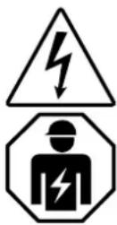
■ The installation, maintenance and eventual replacement of this device must only be carried out by a qualified electrician.
■This device must not be repaired.
■ All applicable local, regional and national regulations must be complied with during the installation, use, maintenance and replacement of this device.
■ This device should not be installed if, when unpacking it, you observe that it is damaged.
■ Schneider Electric cannot be held responsible in the event of non-compliance with the instructions in this document and in the documents to which it refers.
■ The service instruction must be observed throughout the life time of this device.
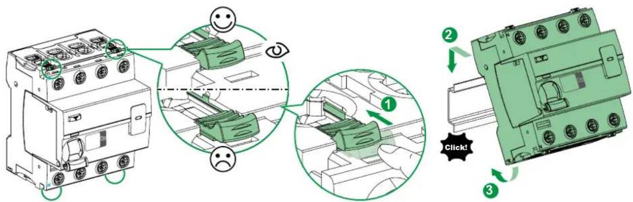
Installation
△ ▲ DANGER
HAZARD OF ELECTRIC SHOCK, EXPLOSION, OR ARC FLASH
■Turn off all power supplying this device before working on it.
■ Use a voltage tester with a suitable rated voltage, in order to check that all active conductors aren't energized.
■ Do not consider the Voltage Presence LED as a substitute for the voltage test.
Failure to follow these instructions will result in death or serious injury.
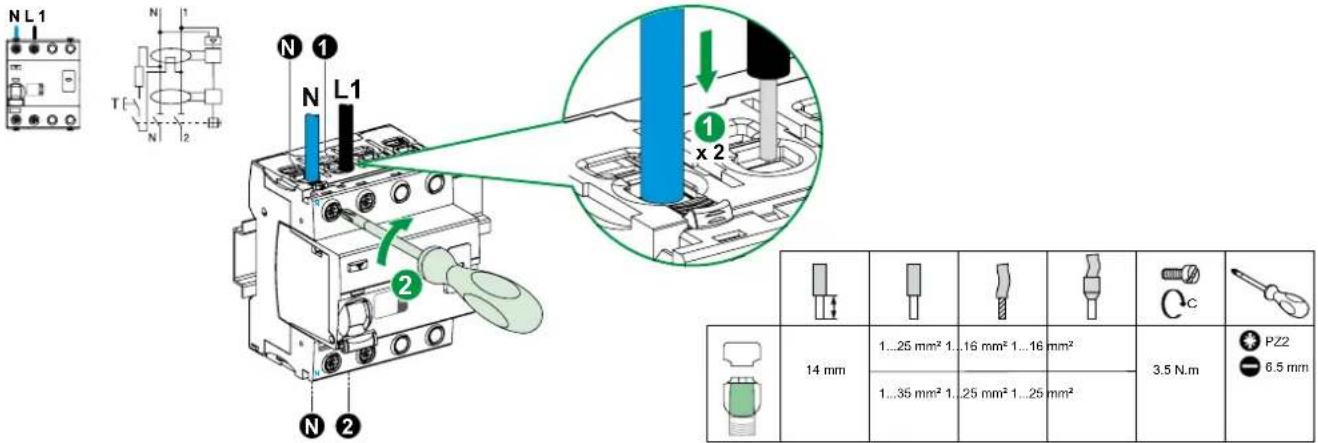
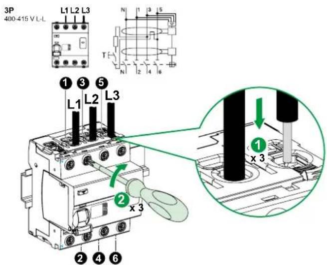
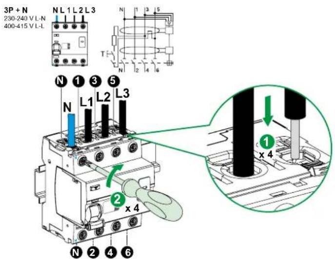
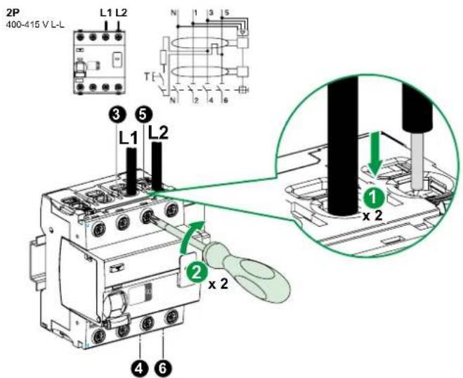
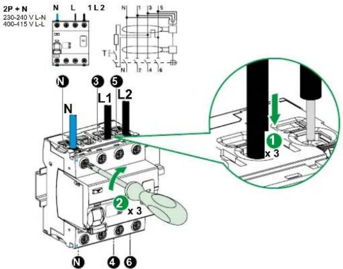
Wiring
Electrical wiring
■ Wire all active conductors and external cables (L1, L2, L3 and the neutral conductor N) to the device, paying attention to the current flow direction, namely that the input terminals are N, 1, 3, 5 and the consumer system side is N, 2, 4, 6.
■Remember to test your product after installation.
1P + N
230-240 V L-N
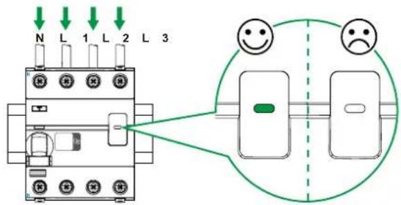
Voltage presence LED
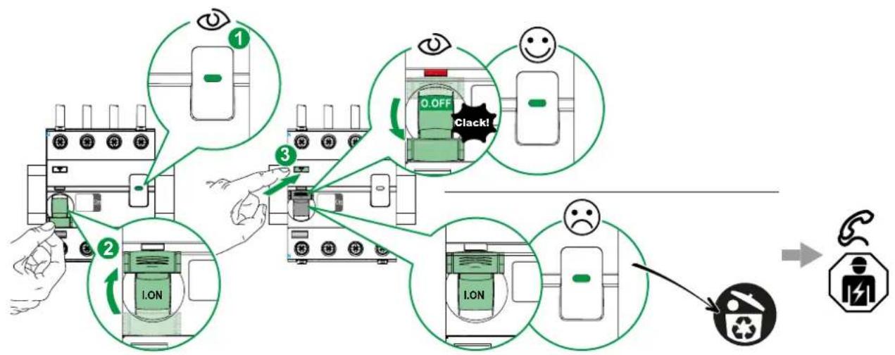
Operating Test
WARNING
PRODUCT OUT OF ORDER
Run a self diagnostic test of device after installing it, and then at regular intervals by pressing the Test button (marked T). (see drawing below).
Failure to follow these instructions can result in death, serious injury, or equipment damage.
flowchart
graph TD
    A["1 Eye"] --> B["2 Lock"]
    B --> C["3 Clapping"]
    C --> D["4 Signal Recovery"]
    D --> E["End"]
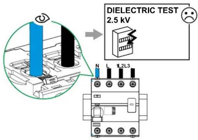
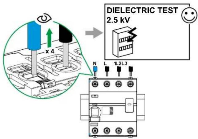
Dielectric Test
NOTICE
RISK OF DAMAGE TO THE EQUIPMENT ACTI9 iID
Disconnect all input and output wires from the Acti9 iID device before running an insulation resistance test (dielectric test).
Failure to follow these instructions can result in equipment damage.
FAQ
Can we use a 4P iID B-SI type in a 2P application?
iID B-SI 2P is now available.
If the voltage is 400 V it's possible to use a 4P for 2P application connecting the terminals between 3/5 and 4/6.
Can we use a 4P iID B-SI type in a 3P application?
The iID 4P is well adapted for 3P application.
What precaution shall I take to perform the dielectric test according to the standard?
If the test is performed above 500 V peak (for example 2 kV 50 Hz) all terminals must be disconnected.
What is the coordination table for iID B-SI type?
Schneider Electric MCB's provide complete information in the coordination table CA908023E in Acti9 catalog or website.
What recommendations do you have for an RCD connected Upstream or in parallel of an iID BSI type?
You will find more information in Earth Leakage Protection Guide CA908066E.
What is the heat dissipation for iID B-SI type in Watt?
For all ratings, you will find more information in the catalog CA908009E.
Where can I find the technical characteristics of the contacts for Open/Close Fault Signal auxiliary?
For all Acti9 products, you will find information in the auxiliary catalog for Open/Close Fault Signal auxiliary CA907002E.
What is the tripping time for ID B-SI type?
In addition to standards IEC 61008-2 and IEC 62423, you will find more information in Earth Fault Protection guide N° CA908066E.
What is the U value?
U_i=250 V 2P; U_i=500 V 4P, you will find more information in catalog CA902055E.
What is the U_imp value?
U_imp=6 kV ; you will find more information in catalog CA902055E.
Is the iID B-SI type with auxiliaries free of silicone?
Yes, our products are green premium, you will find more information in the environmental sheet.
Can iID B-SI type be installed on DC network?
No, the iID B-SI type is always installed on the AC part of the installation. There is no RCD offer for DC network.
What is the difference between B-SI type RCCB and A/AC type RCCB?
B-SI type RCCB is the strongest RCCB in the market, it includes the AC/A and F protection in its design, including electronics that can filter multifrequency for which A/AC type is blinded.
Can I substitute the old B-SI type RCCB with the new iID B-SI type Acti9?
Yes, they are both 4 modules, and the performance of new iID B-SI type Acti9 has been improved. In case you use old B-SI type 4P version for a 2P application, you can now use the 2P reference.
What kind of loads need B-SI type protection?
All loads that injects DC disturbances or could produce frequencies between 16 to 4000Hz in the network.
Examples: Speed Drive (cranes, pumps, lift, HVAC, OEMs machines), Converters for Photovoltaic, Electrical Vehicle, UPS equipment, medical equipment.
Is the iID B-SI type compliant with the 3000A 22.5 kA²s short circuit test?
Yes, the iID B-SI type is compliant to Belgium Standard.
Acti9 iID tipo B-SI
Collegamento
Funzione di prova
AVVERTENZA
PRODOTTO FUORI SERVIZIO
Tilslutning
Elektrisk tilslutning
Test knap
▲ ADVARSEL!
PRODUKT UDE AF DRIFT
flowchart
graph TD
    A["Device 1: Inverter"] --> B["Device 2: Lock with I.ON"]
    B --> C["Device 3: Clack with 0.OFF"]
    C --> D["Device 4: No OK"]
    D --> E["Device 5: Clack with -"]
    E --> F["Device 6: Clack with -"]
    F --> G["Device 7: Clack with -"]
    G --> H["Device 8: Clack with -"]
    H --> I["Device 9: Clack with -"]
    I --> J["Device 10: Clack with -"]
    style A fill:#f9f,stroke:#333
    style B fill:#ccf,stroke:#333
    style C fill:#cfc,stroke:#333
    style D fill:#fcc,stroke:#333
    style E fill:#cff,stroke:#333
    style F fill:#ffc,stroke:#333
    style G fill:#fcf,stroke:#333
    style H fill:#cff,stroke:#333
    style I fill:#ffc,stroke:#333
    style J fill:#cfc,stroke:#333
Dielektrisk test
BEMÆRK
RISIKO FOR BESKADIGELSE AF ACTI9 iID UDSTYRET
Verkabelung
Testfunktion
⚠️ WARNING
GERÄT OHNE FUNKTION
Tilkobling
Elektrisk tilkobling
Testfunksjon
▲ ADVARSEL
PRODUKT UTE AV DRIFT
Kabling
Elektrisk inkoppling
Testfunktion
▲ WARNING
flowchart
graph TD
    A["Device 1: Inverter"] --> B["Device 2: Lock/ON"]
    B --> C["Device 3: Clack!"]
    C --> D["Device 4: Inverter with 0.0FF/Clack!"]
    D --> E["Device 5: Inverter with 0.0% signal"]
    E --> F["Device 6: Inverter with 0.0% signal"]
    F --> G["Device 7: Inverter with 0.0% signal"]
    G --> H["Device 8: Inverter with 0.0% signal"]
    H --> I["Device 9: Inverter with 0.0% signal"]
    I --> J["Device 10: Inverter with 0.0% signal"]
    J --> K["Device 11: Inverter with 0.0% signal"]
    K --> L["Device 12: Inverter with 0.0% signal"]
    L --> M["Device 13: Inverter with 0.0% signal"]
    M --> N["Device 14: Inverter with 0.0% signal"]
    N --> O["Device 15: Inverter with 0.0% signal"]
    O --> P["Device 16: Inverter with 0.0% signal"]
    P --> Q["Device 17: Inverter with 0.0% signal"]
    Q --> R["Device 18: Inverter with 0.0% signal"]
    R --> S["Device 19: Inverter with 0.0% signal"]
    S --> T["Device 20: Inverter with 0.0% signal"]
Isolationstest
OBS
RISK FÖR SKADA PÅ ACTI9 iID-enheten
Connexion
DYSFONCTIONNEMENT DU PRODUIT
Cableado
Conexión eléctrica
Función de prueba
ADVERTENCIA
PRODUCTO FUERA DE SERVICIO
接线
电气连接
运行测试
警告
产品故障
Bedrading
Testfunctie
⚠ WAARSCHUWING
PRODUCT BUITEN WERKING
As standards, specifications and designs change from time to time, please ask for confirmation of the information given in this publication.

- Residual Current Device iID (Type B) SI User Guide and FAQs
- PLEASE NOTE
- Installation
- △ ▲ DANGER
- HAZARD OF ELECTRIC SHOCK, EXPLOSION, OR ARC FLASH
- Wiring
- Electrical wiring
- Voltage presence LED
- Operating Test
- WARNING
- PRODUCT OUT OF ORDER
- Dielectric Test
- NOTICE
- FAQ
- Acti9 iID tipo B-SI
- Collegamento
- Funzione di prova
- AVVERTENZA
- PRODOTTO FUORI SERVIZIO
- Tilslutning
- Elektrisk tilslutning
- Test knap
- ▲ ADVARSEL!
- PRODUKT UDE AF DRIFT
- Dielektrisk test
- BEMÆRK
- Verkabelung
- Testfunktion
- ⚠️ WARNING
- GERÄT OHNE FUNKTION
- Tilkobling
- Elektrisk tilkobling
- Testfunksjon
- ▲ ADVARSEL
- PRODUKT UTE AV DRIFT
- Kabling
- Elektrisk inkoppling
- ▲ WARNING
- Isolationstest
- OBS
- Connexion
- DYSFONCTIONNEMENT DU PRODUIT
- Cableado
- Conexión eléctrica
- Función de prueba
- ADVERTENCIA
- PRODUCTO FUERA DE SERVICIO
- 接线
- 电气连接
- 运行测试
- 警告
- 产品故障
- Bedrading
- Testfunctie
- ⚠ WAARSCHUWING
- PRODUCT BUITEN WERKING
Brand : SCHNEIDER
Model : A9Z61263
Category : Circuit breakers