
mPro400GCD - Industrial Controller Cleco - Free user manual and instructions
Find the device manual for free mPro400GCD Cleco in PDF.

| Brand | Cleco |
| Model | mPro400GCD-P-STO |
| Category | Industrial controller |
| Weight | 12.7 kg (controller only) / 13.8 kg (with mounting plate) |
| Power supply | 100-240 VAC ±10%, 2-1 A, 50-60 Hz, 1600 VA max, 45 W idle |
| Main function | Control for NeoTek corded tools or BD integrated screwdrivers, configurable as Primary or Secondary controller, up to 16 tightening channels |
| Safety function | STO (Safe Torque Off) with SIL2, category 3, PL d, differential time 100 ms |
| Display | 10.4" TFT touch screen, 800x600 resolution |
| Operating system | Real-time OS-9000, startup without mechanical unit |
| Interfaces | 2x RS232, 16 digital inputs/outputs 24 V, TSnet bus, ARCNET, Anybus Compact Com (optional) |
| Memory | CF card (system) + optional SD card |
| Ambient conditions | 0 to 45 °C, humidity 10-90% non-condensing, max altitude 3000 m, IP42 |
| Maintenance | No general maintenance; exterior cleaning with dry or damp cloth; alcohol disinfection allowed |
| Electrical safety | Class I, overvoltage protection CAT II, fuse 16 AT 250 V |
| Compliance | FCC Part 15 Class A, ISDE, CE, UKCA |
| Accessories | TSnet cables, STO cables, power cable, termination connectors, plug retention bracket |
| Repairability | Do not open; repairs exclusively by Apex Tool Group; return to Sales & Service Center |
| Disposal | Follow local directives, sort components, deliver to collection point or after-sales service |
| Manual languages | FR, DE, EN, ES, PL, PT, ZH |
Frequently Asked Questions - mPro400GCD Cleco
User questions about mPro400GCD Cleco
0 question about this device. Answer the ones you know or ask your own.
Ask a new question about this device
Download the instructions for your Industrial Controller in PDF format for free! Find your manual mPro400GCD - Cleco and take your electronic device back in hand. On this page are published all the documents necessary for the use of your device. mPro400GCD by Cleco.
USER MANUAL mPro400GCD Cleco
Cleco
Tame the Line
Copyright © 2025 Apex Brands, Inc. All rights reserved.
Disclaimer
Apex Tool Group reserves the right to modify, supplement, or improve this document or the product without prior notice.
Trademark
Cleco is a registered trademark of Apex Brands, Inc.
Apex Tool Group
670 Industrial Drive
Lexington, SC 29072
USA
Manufacturer
Apex Tool Group GmbH
Industriestraße 1
73463 Westhausen
Germany
Content
EN
1 About this Document....9
2 Safety 9
2.1 Warnings and Notices 9
2.2 Symbols on the Product 10
2.3 Intended Use 10
2.4 Foreseeable misuse....10
2.5 Operator Training 10
2.6 Personal Protective Equipment....10
2.7 Safety instructions relevant to the system....10
2.8 FCC- and ISED Compliance 12
3 Items Supplied....12
4 Accessory....12
5 Transport 12
6 Product Description....12
7 Pin Assignment 12
8 Data Storage 15
9 Initial Operation 15
10 STO Safety Function....16
10.1 Description 16
10.2 Safety 16
10.3 Performance Features....16
10.4 Diagnostic Coverage (DC) 17
10.5 Interfaces....17
10.6 Control Signals....18
10.7 Diagnostics....19
10.8 Time response....19
10.9 Installation....20
10.10 Function Test....21
11 Technical Data 22
11.1 Dimensions....22
11.2 Ambient conditions....22
11.3 Electrical Data 22
11.4 Safety Technology....22
11.5 System Data....23
11.6 Weight 23
12 Disposal....23
DE
10.4 Diagnosedeckungsgrad (DC)....33
10.9 Installation 36
10.9 Installation 67
This document is intended for qualified employees responsible for installation and maintenance (installer, maintenance technician, service, operator).
It contains information
• for safe and appropriate handling of the product.
- on function.
• to technical data and maintenance.
The original language of this document is German.
Programming instructions are not included. See separate programming instructions for this.
Validity
This document is valid for the following products:
mPro400GCD-P-STO
Revision History
| Revision date | Revision | Name | Description |
| January, 2024 | D | GGL | General update |
| August, 2025 | E | GGL | Restriction: range supply voltage, BD(E) series added |
Software Requirements
| Order No. | Description |
| S168813 | Controller software |
| S168691 | mProRemote Professional |
Other Documents
| Number | Document |
| P1730PM | Programming Manual – Tightening Sequences |
| P2279SB | System Handbook – NeoTek |
| P2280PM | Programming Manual – S168813 mPro400GC(D) & mPro200GC(-AP) |
| P2361JH | Installation Instruction – mPro400GCD-(...) |
| P2525TS | Troubleshooting - mPro400GC(D) |
| P3357C | EU Declaration of Conformity – mPro400GCD-P-STO |
Symbols in the Text
italic Menu options (e.g., Diagnostics) input fields, check boxes, radio buttons or dropdown menus.
Indicates selection of a menu option from a menu, e.g., File > Print.
<...> Specifies switches, pushbuttons or the keys of an external keyboard, e.g.,
Courier Indicates Filenames and paths, e.g., setup.exe.
- Indicates lists, level 1. - Indicates lists, level 2.
a) Indicates options. b)
Indicates results.
- (...) Indicates action steps.
- (...)
▶ Indicates single action steps.
Sales & Service Center ClecoSales & Service Center, see last page.
2 Safety
▶ Read all safety warnings and instructions. Failure to follow the directions and safety instructions could result in an electric shocks, burns and/or serious injuries.
▶ Keep this document in a safe place for future reference!
These safety instructions must be accessible at all times to all persons who use the product.
2.1 Warnings and Notices
Warning notes are identified by a signal word and a pictogram:
- The signal word describes the severity and probability of the impending danger.
• The pictogram describes the type of danger.

Danger
A symbol combined with the word Danger indicates a hazard with a high level of risk which, if not avoided, will result in death or serious injury.

Warning
A symbol combined with the word Warning indicates a hazard with a medium level of risk which, if not avoided, could result in death or serious injury.


Caution
A symbol combined with the word Caution indicates a hazard with a low level of risk which, if not avoided, could result in minor or moderate injury.

Note
A symbol combined with the word Note indicates a potentially harmful situation which, if not avoided, could result in damage to property or the environment.

General instructions include application tips and useful information, but no warnings against hazards.
Structure Of Warnings


Caution
Type and source of danger.
Possible consequences of non-observance.
▶ Measures to avoid danger.
2.2 Symbols on the Product

Electric voltage

Read the operating instructions carefully

CE compliant
The product corresponds to the prescribed technical requirements in Europe.

Observe and comply with all local disposal guidelines for all components of this equipment and it's packaging.

UKCA compliant.
The product corresponds to the prescribed technical requirements in Great Britain.
2.3 Intended Use
The user is liable for any damage caused by improper use. Use the product only under the following conditions:
▶ Only use in industrial tightening processes.
▶ If the product is opened, the warranty is voided. In the event of repair, send the complete product to your Sales & Service Center. Repairs are only permitted personnel authorized by Apex Tool Group.
▶ Only use in conjunction with the components listed in the EU Declaration of Conformity.
▶ Use under the specified ambient conditions.
▶ Operate with the specified supply voltage.
▶ For power supply use only the power supply cable supplied by Cleco.
▶ Operate within the power range specified in the technical data.
2.4 Foreseeable misuse
▶ DO NOT bypass safety devices.
▶ DO NOT use the product in potentially explosive areas.
▶ DO NOT use the product in a damp environment or outdoors.
▶ DO NOT use the product in living areas.
▶ DO NOT use the product in conjunction with cutting tools (drills, milling cutters, grinders...).
▶ DO NOT use the product with components other than those specified in the Declaration of Conformity.
▶ DO NOT use the product for applications other than screwing in and loosening nuts and bolts.
▶ DO NOT use the product to lift suspended loads or similar stored energy.
▶ DO NOT use the product as a climbing aid.
2.5 Operator Training
The tightening system may only be put into operation, set up and maintained by personnel who have been trained and qualified by the Apex Tool Group.
The product has been preset by the Apex Tool Group. Changes to the factory settings may only be carried out by a specialist ^1 .
The owner/operator must ensure that new operating and maintenance personnel are instructed in the operation and servicing of the tightening system to the same extent and with the same care.
Personnel undergoing schooling/training/instruction may only work with the tightening system under the supervision of an experienced person.
2.6 Personal Protective Equipment
▶ When working with rotating parts, it is not permitted to wear gloves.
Recommendation: Freely rotating u-GUARD protected tightening tools from APEX.
▶ Wear suitable clothing. Do not wear loose clothing or jewelry.
▶ Wear safety shoes.
▶ Wear protective goggles if there is a risk of dirt or parts being ejected.
▶ Wear a hair net, if necessary.
2.7 Safety instructions relevant to the system
It is imperative to observe the national, state and local regulations and standards.
▶ Do not make any changes to the controller, protective devices or accessories without the prior written consent of Apex Tool Group.
▶ Do not open the controller or components of the controller either for troubleshooting or other work. Any intervention can cause serious injuries in case of a failure.
Cleco
Risk of injury due to electric shock
In the event of a fault, the controller can carry voltage. An electric shock can lead to cardiovascular arrest, respiratory failure, burns and serious injuries or death.
▶ Switch off the controller before connecting the power supply and tool cables, when converting, unplugging the plug connector, cleaning or decommissioning.
▶ Do NOT open the system components. After interrupting the power supply, a dangerous voltage may still be present for 10 minutes.
▶ Do not operate the tightening system if the housing, cable or tool is damaged.
In the event of any malfunctions, never repair the tightening system yourself without knowing how to do so! Inform the local repair center or the responsible Sales & Service Center.
During installation
▶ Use suitable lifting equipment to lift the controller to the desired installation location.
▶ Make sure that the controller is firmly installed and secured (see Quick Reference Guide).
▶ Route cables and lines such that there is no risk of damage or tripping hazard.
▶ Comply with the permissible bending radius of the cable.
▶ Use an approved power cable with suitable ratings.
For 115 VAC: Use a cable with a larger cross-sectional area.
Applies to controller with STO: Use the emergency switching-off function in the machine. Connect a suitable safety relay.
▶ Applies to controller with STO: Ensure protection against automatic tool restart according to the required safety category of emergency switching-off applications, e.g. with an external safety relay.
Before commissioning
▶ Only operate on an earthed network with a neutral conductor (TN system). Operation without a neutral conductor (IT network) is not permitted.
▶ Make sure the PE connection is compliant with standards.
▶ A type "A" residual current operated device (RCD) is recommended to protect the supply line.
▶ Prior to commissioning, carry out the protective conductor measurement in accordance with the local regulations (in Germany, DGUV Regulation 3).
▶ Do not switch the controller on until all connections have been properly established.
During operation
▶ Protect the controller against moisture.
▶ In the event of unusual noises, heating or vibrations, switch off the controller immediately.
▶ Pull out the power plug and have the tightening system checked by qualified personnel; have it repaired if necessary.
▶ Never pull the plug on the cable from the outlet.
▶ Protect the cables from heat, oil, sharp edges or moving parts.
▶ Replace damaged cables immediately.
▶ Keep the connections between the controller and tool clean.
▶ Keep the workstation tidy to prevent injury or damage to the tightening components.
▶ Ensure that there is enough room at the workstation.
Danger due to incorrect torque measurement
An undetected NOK tightening could have life-threatening consequences.
▶ It is imperative that the tool is recalibrated (or a capability analysis performed) after improper use (dropped, mechanical overload ...).
For category A rundowns (VDI 2862) which are critical for safety, activate a redundancy measurement (e.g., current redundancy).
▶ Introduce regular measuring equipment monitoring for the machines and tools.
▶ Only work with a tightening system that is working correctly. If in doubt, contact a Sales & Service Center.
Danger due to an unexpected motor start or an expected, but not functioning, stop
Despite redundant control components and monitoring functions, it can happen in very rare cases that the motor starts unexpectedly.
Possible reasons: Remote control of diagnostic functions, bit dump in the memory of the controller.
Starting from the tool, mechanical hazards can result, such as jerks/jolts due to reaction torque and the risk of injury due to being reeled in and seized.
▶ Use sufficiently dimensioned reaction devices for the maximum possible torque.
▶ After switching the controller on, wait until the boot process is complete. This takes about 1 minute. Do not switch on/off until then.
During maintenance
The controller is generally maintenance-free.
▶ Comply with local regulations regarding servicing and maintenance for all operating phases of the tightening system.
During cleaning
▶ Only clean the outside of the tool with a dry or slightly damp cloth.
▶ Never immerse the controller or tool in liquids.
▶ Do not use a high pressure cleaner.
▶ Disinfection of the surfaces is permitted with alcohol-based disinfectants.
Use of the secondary controller
Up to 15 secondary controllers can be added to a primary controller. When the secondary controller is switched off or fails, the TSnet bus communication is interrupted. The loss of communication to the primary controller affects the secondary controller:
• No results are reported back to the primary controller.
- No more fastenings are started.
- A running fastening process shows the error message SA (aborted by removal of the start signal) if the
TSnet connection was interrupted during the fastening process.
- A shutdown signal is no longer received, so shutdown only takes place:
- by activating the STO safety shutdown
- after reaching the switch-off criterion or
- via a safety shutdown after two seconds.
WARNING!
During remote start operation (multiple fasteners), an interruption in the TSnet bus leads to a delayed stop of the tool. This delay is 2 seconds.
Risk of injury due to dangerous movements
Inadequate emergency switching-off devices could have potentially fatal consequences.
The necessity of an emergency switching-off and its implementation are the responsibility of the operator and subject of his risk analysis!
▶ Ensure accessible and effective emergency switching-off devices. Unlocking an emergency switching-off device must not cause an uncontrolled restart of the system!
▶ Before switching the system on, check the function of the emergency switching-off devices.
▶ Be sure to observe further safety instructions in the chapter on the STO safety function.
2.8 FCC- and ISED Compliance
This product complies with Part 15 of the FCC Rules. Any changes or modifications not expressly approved by the manufacturer could void the user's authority to operate this product. Operation is subject to the following two conditions:
• This product may not cause harmful interference.
- This product must accept any interference received, including interference that may cause undesired operation.
FCC Responsible party
Name: William Cain
Position: Director, R&D
Address: 670 Industrial Drive
Lexington, SC 29072
United States
This product has been tested and found to comply with the limits for a Class A digital device, pursuant to Part 15 of the FCC Rules. These limits are designed to provide reasonable protection against harmful interference when the product is operated in a commercial environment. This product generates, uses, and can radiate radio frequency energy and, if not installed and used in accordance with the instruction manual, may cause harmful interference to radio communications.
Operation of this product in a residential area is likely to cause harmful interference in which case the user will be required to correct the interference at his own expense.
3 Items Supplied
▶ Verify the scope of delivery for completeness on the basis of dispatch papers.
- Controller
• This Hardware Description
- Quick Installation Guide
• EC Declaration of Conformity
- Warranty
• Order no. 541683-03 – Power cable EU 230 VAC
• Order no. 541683-01 – Power cable USA 115 VAC
• Order no. 541683-02 – Power cable USA 230 VAC
• Order no. 544004-1 – Plug locking mechanism
• Order no. 961893PT – Termination plug STO
• Order no. 962405PT – Plug STO, bridged
• Order no. S981211 – Mating Connector X9/X10 (2×)
4 Accessory
• Order no. 962037-(...) - Cable TSnet
• Order no. 961924-(...) – Cable STO cable
5 Transport
▶ Transport or store the product in its original packaging. The packaging is recyclable.
▶ If the packaging is damaged, check the part for visible damage. Inform the carrier and, if necessary, your Sales & Service Center.
6 Product Description
- Controller for use with a NeoTek series corded hand tool or a BD series fixtured spindle.
- Control configurable for use as primary or secondary control.
• A total of up to 16 screw channels can be realized. - Controller with the suffix STO in the type name are equipped with the STO safety function, see chapter 10 STO Safety Function, page 16
7 Pin Assignment
This chapter describes the Cleco specific connectors. Standard plugs are not considered. All connections are short-circuit proof.
X5,6 - Additional Devices
• All outputs provide RS232 conforming signals.
• The inputs allow voltages from -15 V to +15 V.
Voltages < 0.8 V correspond to a zero.
- Voltages > 2.4 V are interpreted as a one.
- Open inputs are preset to zero using a pulldown resistor.
- The power supply pins are connected directly to the main board power supply.

Note
Data loss
If the connection is interrupted during operation, a system reset may result.
▶ Do not plug or unplug consumers during operation.
| Pin | RS232-1RS232-2 | 9 Pin D-Sub, pin, with screw lock |
| 1 | - | 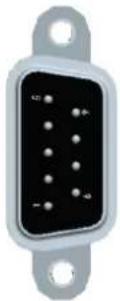 |
| 2 | RxD | |
| 3 | TxD | |
| 4 | - | |
| 5 | GND | |
| 6 | - | |
| 7 | RTS | |
| 8 | CTS | |
| 9 | - |

Installation Instructions for Fieldbus Module
Push the module in as far as it will go, then press it slightly to the right and push it in completely. The nose on the module must not rest on the circuit board.
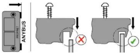
X7, X8 – Anybus Compact Com
Optional slots for Anybus CC M30 modules.
X9, X10 - Digital Inputs/Outputs
This chapter describes the wiring of the inputs/outputs. The supply for each signal group (X9, X10) is electrically connected.
• 8 inputs/8 outputs, opto-isolated for 24 V level.
• Output current: 0.5 A per output, 1 A total.

Note
Overload shutdown
The current monitor switches off the output in the event of an overcurrent.
▶ A single device must not require a current of more than 0.5 A.
| Signal X9 | Signal X10 | |||||
| Pin | I/O | Descrip-tion | Pin | I/O | Descrip-tion | |
| 12 | Supply GND Int. | 24 | Supply GND Int. | |||
| 11 | Supply GND I/O | 23 | Supply GND I/O | |||
| 10 | Output | O3 | 22 | Output | O7 | |
| 9 | Output | O2 | 21 | Output | O6 | |
| 8 | Output | O1 | 20 | Output | O5 | |
| 7 | Output | O0 | 19 | Output | O4 | |
| 6 | Input | I3 | 18 | Input | I7 | |
| 5 | Input | I2 | 17 | Input | I6 | |
| 4 | Input | I1 | 16 | Input | I5 | |
| 3 | Input | I0 | 15 | Input | I4 | |
| 2 | Supply +24 V Ext. | 14 | Supply +24 V Ext. | |||
| 1 | Supply +24 V Int. | 13 | Supply +24 V Int. | |||
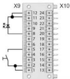
Internal power supply (example)
Fig. 1-1: 2x12 pol. Phoenix MCD 0.5/24-G1-2.5
Inputs
• Use of an internal voltage source to supply the inputs.
• Pin 1 and 13 are the voltage source for the inputs.
• Pin 2 and 14 must be connected to Pin 1 or 13.
Outputs
- Use of an internal voltage source to supply the outputs.
- Pin 11 and 23 (common GND) serve as a "return line" for the outputs.
• Pin 11 and 23 must be connected to Pin 12 or 24.
External power supply (example)
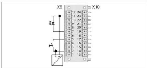
Fig. 1-2: 2x12 pol. Phoenix MCD 0.5/24-G1-2.5
EN
Requirement for external voltage source:
Use of a PELV (Protective Extra Low Voltage) voltage source 24 VDC ±10 %.
Inputs
- Use of an external voltage source to supply the inputs.
- Connect pin 2 and pin 14 to the external 24 VDC voltage source.
- Connect pin 11 and pin 23 (GND together) to the external voltage source as reference potential for the inputs.
Outputs
- Use of an external voltage source to supply the outputs.
- Connect pin 2 and pin 14 to the external 24 VDC voltage source.
- Connect pin 11 and pin 23 (GND together) to the external voltage source as return line for the outputs.
X21 – System Bus TSnet Out
| Pin | Signal | Circular Connector M12 socket, 8 Pin, X-Coded |
| 1 | Tx + | 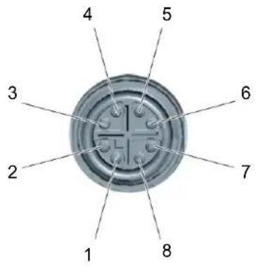 |
| 2 | Tx - | |
| 3 | Rx + | |
| 4 | Rx - | |
| 5 | GND_Int. | |
| 6 | GND_Int. | |
| 7 | +24 VDC_Int. | |
| 8 | +24 VDC_Int. |
X22 - ARCNET System Bus
| Pin | Signal | Circular Connector M12 pin, 8 pin, A-Coded |
| 1 | n. c. | 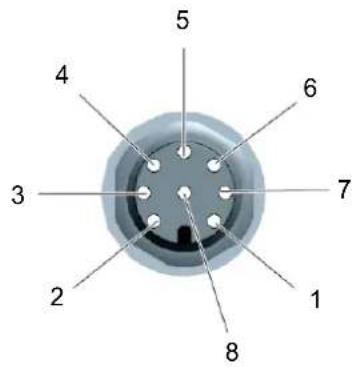 |
| 2 | DATA-B | |
| 3 | GND | |
| 4 | +5 VDC | |
| 5 | DATA-A | |
| 6 | n. c. | |
| 7 | 0 VDC | |
| 8 | +24 VDC |
X23 - Supply
| Description | Connector IEC, C14 |
| Connector with Fuse Holder | 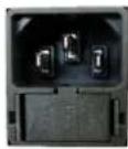 |
| Fuse, Schurter type 0034.3129, 5 × 20 mm, 16 AT, 250 VAC, Breaking capacity, 100 A |

Note
Interruption of power supply
The device plug may come loose unnoticed.
▶ Use plug locking mechanism order no. 544004-1. See Quick Installation Guide.
X24 – Tool Connector Digital
30/50/70 Series
BD Series
| Pin | Signal | Circular ConnectorM23, socket |
| 123 | Power | 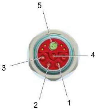 |
| 4 | PE (functional ground) | |
| 5 | Tool bus |
X25 - Tool Connector Analog
Hand tool series 18, 48, 67
| Pin | Signal | Circular Connector ECTA socket, push-pull |
| 123 | Power |  |
| 4 | PE(functional ground) | |
| 5 Tool bus | ||
X41, X42 – Emergency Stop (STO)
Signal assignment see chapter 10.5 Interfaces, page 17.
| Connection | Function STO | Circular ConnectorM12, 8 polig, A-Coded |
| X42 STO OUT | 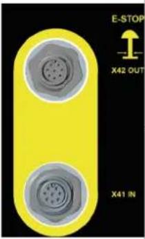 | Pin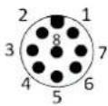 |
| X41 STO IN | Socket |
8 Data Storage
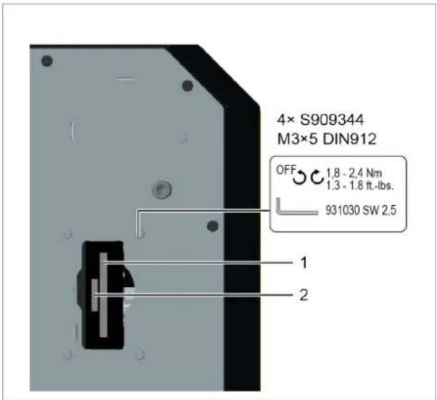
Fig. 1-3: Storage access on the backside
| Pos. | Name | Function |
| 1 | CF Card (Compact-Flash) | Necessary for the operating system and archiving files/applications. Included with controller. |
| 2 | SD Card, optional | Function is software-dependent: software update, save/load parameters, data archive files. |

Note
Data loss
Serious system errors and data loss if not observed:
▶ Only remove or insert the SD card when the supply voltage is switched off.
9 Initial Operation
▶ Initial operation see document P2361JH.
10 STO Safety Function
10.1 Description
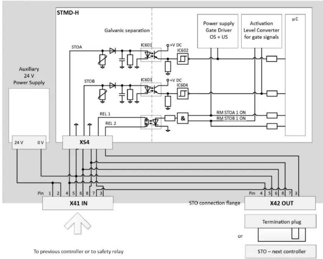
This function prevents force-generating energy from being supplied to the motor. This safety function corresponds to an uncontrolled shutdown as per IEC 60204-1, stop category 0 (DIN EN 61800-5-2 chapter 4.2.3.2). STO: Safe torque off.
It is possible to link the STO safety function with several controllers. The Emergency Stop IN/OUT interface is available for this purpose.
10.2 Safety
 | Danger |
| Electrical voltage!Risk of fatal electric shock.The STO safety function only provides protection against dangerous movements, not against electric shock.Safety instructions Risk of injury from electric shock, see chapter 2.7 Safety instructions relevant to the system, page 10 must be observed. | |
 | Caution |
| Failure of the STO safety functionMaterial damage and personal injury may result.Report safety-critical faults that lead to an unsafe state to Apex Tool Group without delay.If a rundown is blocked by a fail-safe state, even though the STO safety function has not been explicitly requested, there is a fault in the safety function. Have the system checked for faults by a qualified specialist.Replace and check defective safety-critical components without delay.After reaching the maximum number of the service life see chapter 11.4 Safety Technology, page 22: Replace controller. | |
 | Note |
| Risk of the motor starting in the event of multiple faults in the controllerIf the final stage of the tightening module in the controller fails during the STO state (simultaneous short circuit of 2 power semiconductors in different phases), there may be a limited locking movement of the rotor in the motor. The angle of rotation corresponds to a pole pitch acting on the output drive with gear reduction. The angle of rotation for Cleco power tools is always ≤15°. |
10.3 Performance Features
- Reaching the STO safety function.
• Potential-free feedback contact for the operating status.
When the STO safety function is active, the power supply is safely interrupted by two separate shutdown paths to the motor in the tool. The motor can not produce any torque and therefore no dangerous movements. There is no monitoring of the standstill position. This is relevant, for example, for torques generated by loads, such as suspended loads, or by preloaded spring drives. In such cases, additional measures for shutdown must be provided that prevent these reactions - these must be ensured and brought about in a safety-related manner.
flowchart
graph TD
    A["Auxiliary 24 V Power Supply"] --> B["24 V 0V"]
    B --> C["X41 IN"]
    C --> D["STO connection flange"]
    D --> E["X42 OUT"]
    E --> F["Termination plug"]
    F --> G["STO – next controller"]
    H["STMD-H"] --> I["Galvanic separation"]
    I --> J["IC601 +V DC IC602"]
    I --> K["IC603 +V DC IC604"]
    I --> L["&"]
    M["Power supply Gate Driver OS + US"] --> N["μC"]
    O["Activation Level Converter for gate signals"] --> P["μC"]
    Q["Rel 1 REL 2"] --> R["Pin 1 Pin 2 3 4 5 6 7 8 9 3"]
    S["Rel 1 & Rel 2"] --> T["Pin 4 Pin 5 6 8 7 3"]
    U["To previous controller or to safety relay"] --> V["Pin 1 Pin 2 Pin 3 Pin 4 Pin 5 Pin 6 Pin 7 Pin 8 Pin 9 Pin 10 Pin 11 Pin 12 Pin 13 Pin 14 Pin 15 Pin 16 Pin 17 Pin 18 Pin 19 Pin 20 Pin 21 Pin 22 Pin 23 Pin 24 Pin 25 Pin 26 Pin 27 Pin 28 Pin 29 Pin 30 Pin 31 Pin 32 Pin 33 Pin 34 Pin 35 Pin 36 Pin 37 Pin 38 Pin 39 Pin 40 Pin 41 Pin 42 Pin 43 Pin 44 Pin 45 Pin 46 Pin 47 Pin 48 Pin 49 Pin 50 Pin 51 Pin 52 Pin 53 Pin 54 Pin 55 Pin 56 Pin 57 Pin 58 Pin 59 Pin 60 Pin 61 Pin 62 Pin 63 Pin 64 Pin 65 Pin 66 Pin 67 Pin 68 Pin 69 Pin 70 Pin 71 Pin 72 Pin 73 Pin 74 Pin 75 Pin 76 Pin 77 Pin 78 Pin 79 Pin 80 Pin 81 Pin 82 Pin 83 Pin 84 Pin 85 Pin 86 Pin 87 Pin 88 Pin 89 Pin 90 Pin 91 Pin 92 Pin 93 Pin 94 Pin 95 Pin 96 Pin 97 Pin 98 Pin 99 Pin 100"]
    style A fill:#f9f,stroke:#333
    style H fill:#ccf,stroke:#333
    style I fill:#cfc,stroke:#333
    style J fill:#fcc,stroke:#333
    style K fill:#fcc,stroke:#333
    style L fill:#fcc,stroke:#333
    style M fill:#fcc,stroke:#333
    style N fill:#fcc,stroke:#333
    style O fill:#fcc,stroke:#333
    style P fill:#fcc,stroke:#333
    style Q fill:#fcc,stroke:#333
    style R fill:#fcc,stroke:#333
    style S fill:#fcc,stroke:#333
    style T fill:#fcc,stroke:#333
    style U fill:#fcc,stroke:#333
    style V fill:#fcc,stroke:#333
    style W fill:#fcc,stroke:#333
    style X fill:#fcc,stroke:#333
    style Y fill:#fcc,stroke:#333
    style Z fill:#fcc,stroke:#333
    style AA fill:#fcc,stroke:#333
    style AB fill:#fcc,stroke:#333
    style AC fill:#fcc,stroke:#333
    style AD fill:#fcc,stroke:#333
    style AE fill:#fcc,stroke:#333
    style AF fill:#fcc,stroke:#333
    style AG fill:#fcc,stroke:#333
    style AH fill:#fcc,stroke:#333
    style AI fill:#fcc,stroke:#333
    style AJ fill:#fcc,stroke:#333
    style AK fill:#fcc,stroke:#333
    style AL fill:#fcc,stroke:#333
    style AM fill:#fcc,stroke:#333
    style AN fill:#fcc,stroke:#333
    style AO fill:#fcc,stroke:#333
Fig. 1-4 STO circuit design
10.4 Diagnostic Coverage (DC)
The Diagnostic Coverage depends on the inclusion of the integrated safety function for the controller into the controller chain, as well as the implemented measures for the diagnostics. If a fault is detected during the diagnostics, suitable measures must be provided to maintain the safety level.
10.5 Interfaces
The STO safety function for the controller is controlled via the digital I/O interfaces X41, X42. The interfaces for all controllers with the STO function are designated the same, highlighted in yellow and functionally identical with the same specifications, see chapter 7 Pin Assignment, page 12.
The STO safety function is requested exclusively via the two digital control inputs STO-A and STO-B. Another connection of the signals, e.g., feedback or auxiliary voltage, is not absolutely required.

Note
Cross-connection detection of the input circuit is not performed by the controller.
All system components allow the short circuit fault exclusion.
The state of the STO safety function is reported back via a potential-free feedback contact (closer). This information is linked in a successive circuit of several controllers with the STO function.
Interface port X41 - IN
Depending on the position of the currently considered control in the STO line (see chapter System Layout, page 119), the interface port X41 is the connection to the previous controller or to the external safety relay.)
By providing an auxiliary power supply of 24 VDC in connector X41, it is possible to supply the voltage to safety relays for normally open contacts, or similar.
| Pin | Signal | Description |
| 1 | 24 VDC | Output auxiliary power supply 24 VDC, for passive control of STO. Reference potential is GND_STO. |
| 2 | 24 VDC | |
| 3 | FB-1-IN | Potential-free Feedback Contact 1 (informative) for the STO stateFeedback contact open: STO not activeFeedback contact closed: STO active |
| 4 | STO-A | Input for control signal A for controlling the STO safety function. Reference potential is GND_STOSTO request at low level simultaneously with low level at STO-B |
| 5 | GND_STO | Reference potential for all voltages at X41. |
| 6 | STO-B | Input for control signal B for controlling the STO safety function. Reference potential is GND_STOSTO request at low level simultaneously with low level at STO-A |
| 7 | FB-2 | Potential-free Feedback Contact 2; for a description see FB-1. |
| 8 | GND_STO | Reference potential for all voltages at X41. |
Interface port X42 - OUT
Depending on whether the currently considered controller is the last in an STO line, or whether another controller follows, the interface X42 is the connection to the next controller or can be left without connecting further. If the feedback contact is evaluated, a termination on the last controller in a line is necessary.
| Pin | Signal | Description |
| 1 | n. c. | - |
| 2 | n. c. | - |
| 3 | FB-1-OUT | Potential-free Feedback Contact 1 |
| 4 | STO-A | Output for control signal A for controlling the STO safety function of the next controller, bridged with X41.4. |
| 5 | GND_STO | Reference potential for all voltages at X42. |
| 6 | STO-B | Output for control signal B for controlling the STO safety function of the next controller, bridged with X41.6. |
| 7 | FB-2 | Potential-free Feedback Contact 2, bridged with X41.7. |
| 8 | GND_STO | Reference potential for all voltages at X42. |
10.6 Control Signals
With the two control inputs STO-A and STO-B, the STO safety function is requested by two channels. They allow the direct connection of safe semiconductor outputs (electronic safety relays, active safety sensors) and of switching contacts (safety relays with relay outputs, passive safety sensors, such as positively driven position switches), see chapter 10.9 Installation, page 20.
To request the STO safety function, the 24 V control voltage at both control inputs STO-A and STO-B is switched off (0 V). If both control signals are switched off simultaneously or within a specified discrepancy time, then the STO safety function is active.
Tolerance ranges are defined for the input voltage range of the control inputs STO-A and STO-B. The amount of energy stored in the components of the STO circuit (e.g., capacitors) depends on the magnitude of the input voltage. During switching operations, these amounts of energy must be charged or discharged. As a result, the dependent values for the switch-off time for the transition to the safe state (STO) come about from the input voltage, see chapter 11.3 Electrical Data, page 22.
For the time response itself see chapter 10.8 Time response, page 19.
Discrepancy time
The transition between a safe and an unsafe state is initiated by level changes at the control inputs STO-A and STO-B. According to the specifications for the safety function, both levels must be identical; otherwise an error message will be generated. A state machine in the controller monitors both signals over time. Due to component tolerances or bouncing
contacts, the level changes never occur at exactly the same time. This is tolerated by the so-called discrepancy time as long as the level changes occur within this time. If the levels of the control signals STO-A and STO-B are different for longer than this time, a transition is made to an error state that can not be reset. The discrepancy time t is 100 ms. This can not be parameterized.

The signals STO-A and STO-B should be switched simultaneously if possible.
Test pulses
Test pulses from safety controllers are not tolerated and must be deactivated for system availability. The exclusive use of Cleco accessories allows the short circuit fault exclusion.
Feedback contact FB
The feedback contact indicates the safe state. If the STO safety function is not active, then the feedback contact is open. This is also the case, for example, when the 24 V logic supply voltage is switched off due to a defect or a failure of the supply voltage. When the STO safety function is active, the relay contact is closed.

Note
The feedback contact has a single-channel design and may be used for diagnostic purposes, but not in the safety circuit.
When switching on, the feedback contact may briefly deviate from the input signals until the controller is ready for operation.
The following table shows the state of the feedback contact, depending on the input signals and the time. A precondition is always the error-free state (Row 1 or 4). The time t is the discrepancy time 100ms .
| Row | STO-A | STO-B | FB closed | Leads to diagnostic error after Δt |
| 1 | 0 | 0 | 1 | 0 |
| 2 | 0 | 1 | 0 | →Δt→1 |
| 3 | 1 | 0 | →Δt→1 | →Δt→1 |
| 4 | 1 | 1 | 0 | 0 |
Overvoltage and polarity reversal protection
The control inputs STO-A and STO-B are protected against overvoltages and against the polarity reversal of the control voltage, see chapter 11 Technical Data, page 22.
The 24 VDC auxiliary voltage supplied at X41 is short-circuit proof. However, a short circuit or overload leads to the failure of all the internal logic voltages and thus to the failure of the primary function.
10.7 Diagnostics
The STO safety function is monitored in the controller for plausibility and operability.
STO status signal to control
Within the software, the status of the STO safety function (1 = OK, 0 = STO triggered) is available at Input 10 on the I/O level under device TM_DIDO.
If this status information is present in the application, this must be assigned accordingly by the operator. It is advisable to use the software input Emergency Stop. Assignment is not necessary for safety reasons.
Fail-Safe state
If a fault in the safety technology is detected, e.g., if, for example, control signals STO-A and STO-B have unequal levels or there is a circuit defect, then a fault is triggered internally. This fault can not be reset or can only be reset by a restart, i.e., further start attempts no longer lead to the turning on of the output drive.
It is assumed that there is an external fault and the controller must be switched off. If the fault persists after checking the external controller, then there is a defect in the controller and it must therefore be replaced.
10.8 Time response
The control signals STO-A and STO-B are equivalent in regards to their use, although the signals operate different shutdown paths. They are described in terms of the time response as a single, exchangeable STO signal.
The time from the shutdown of an STO signal to the activity in the final stage of the controller is determined by the external circuitry (see chapter 10.6 Control Signals, page 18), including controllers connected in parallel. The values given here refer to the Passive circuit with a controller and the maximum cable length. The time response is different for each layout and must be checked at startup to see if it meets the minimum requirements.
10.9 Installation
When installing and wiring the signals, the requirements of EN 60204-1 must be met. In this case, particular attention must be paid to measures for short circuit fault exclusion. For the STO cables 961924-xxx, the STO signals are individually protected by a ground connection. The connection to the first controller, and from controller to controller, must not be longer than 60 m; in total in the system, a total length of up to 200 m is permitted for all of the STO connections.
The following circuit examples show the intended wiring of the STO interfaces. An analogous other use or connection is not permitted.
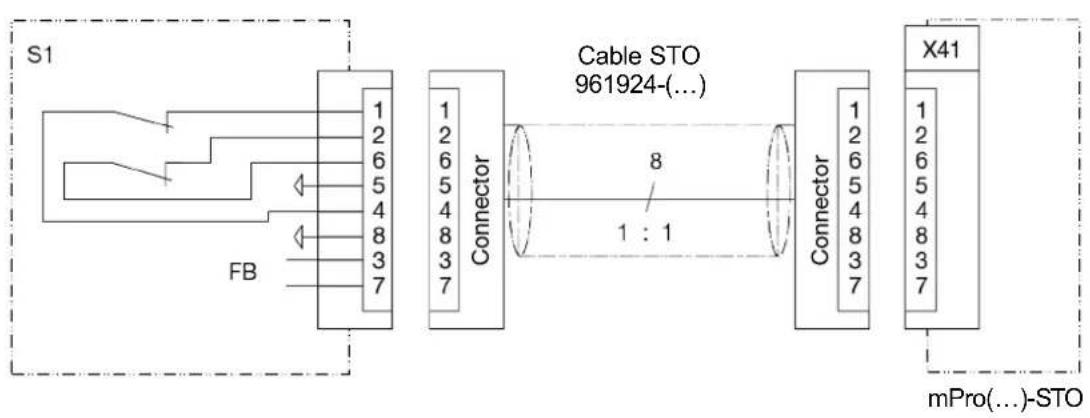
Passive circuit X41
flowchart
graph LR
    subgraph S1
        A["FB"] --> B["Connector"]
        B --> C["Cable STO 961924(...)"]
        C --> D["X41"]
    end
    A -->|1:1| C
    B -->|8| C
    C -->|1:1| D
    style S1 fill:#f9f,stroke:#333
    style X41 fill:#bbf,stroke:#333
Abb. 1-5
The STO safety function can be requested by various devices. The switch S1 can be, for example, an emergency switch-off device, a safety door switch, a light curtain or a safety relay. The safety requirement is 2-channel via the switch S1 and leads to the 2-channel shutdown of the final stage - therefore, this structure is for Category 3. The auxiliary power supply 24 V for signal generation is provided on the interface.
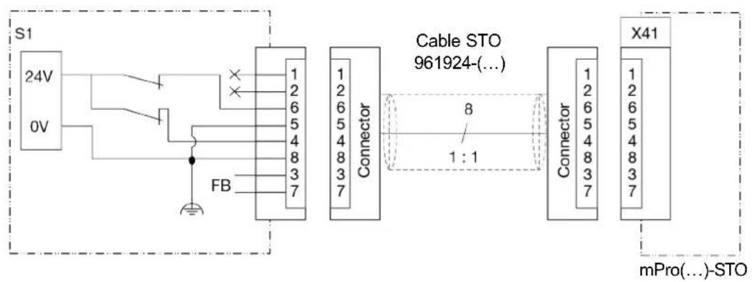
Active circuit X41
flowchart
graph LR
    S1["24V"] -->|0V| FB
    FB -->|FB| Connector1["Connector"]
    Connector1 -->|8| Connector2["Connector"]
    Connector2 -->|1:1| CableSto["Cable STO 961924-(...)"]
    CableSto -->|X41| mPro["mPro(...)-STO"]
Abb. 1-6
The STO safety function can also be requested through active, fail-safe outputs of a PLC or with contacts as in Passive circuit X41, but with an external power supply. For an external power supply, only PELV power circuits and PELV power sources may be used. The voltage source must provide a nominal voltage of 24 VDC (an absolute minimum output voltage of 22 VDC) with at least 0.5 A.
Shut down of STO safety function X41
1
EN
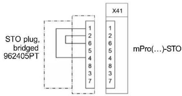
Abb. 1-7
If the STO safety function is not required in a controller, the function can also be deactivated by means of jumpers in a connector.

Caution
Necessary safety function STO disabled
With the circuit shut down, the STO function is bypassed and thus disabled.
If the safety function is required due to a risk assessment, ensure that the circuit shown is replaced by an STO circuit.
Connection X42
Safety Circuit
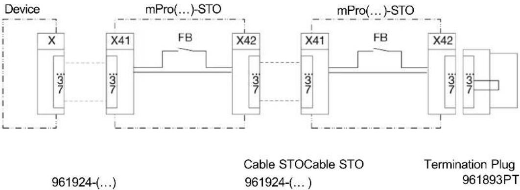
flowchart
graph LR
    A["Device"] --> B["X"]
    B --> C["X41"]
    C --> D["X42"]
    D --> E["X41"]
    E --> F["X42"]
    F --> G["Termination Plug 961893PT"]
    subgraph "mPro(...)-STO"
        H["X41"] --> I["X42"]
    end
    subgraph "Cable STOCable STO"
        J["X41"] --> K["X42"]
    end
    subgraph "Termination Plug"
        L["X42"] --> M["Termination Plug 961893PT"]
    end
    A -.->|3/7| B
    C -.->|3/7| C
    D -.->|3/7| D
    E -.->|3/7| E
    F -.->|3/7| F
    G -.->|3/7| G
    H -.->|FB| I
    J -.->|FB| J
Abb. 1-8
The connection to X42 at the last controller in a system is only required if the feedback contact FB is evaluated. Otherwise, the X42 interface can also remain open. For termination - which means closing the feedback path - use termination connector 961893PT.
10.10 Function Test
▶ Check the functioning of the safety device at defined time intervals.
It is the responsibility of the operator to choose the type of test and the time intervals during the required time period. The test shall be carried out in such a way that the proper functioning of the safety device is demonstrated in the interaction with all the associated components. For maximum interval between two tests, see chapter 11.4 Safety Technology, page 22.
11 Technical Data
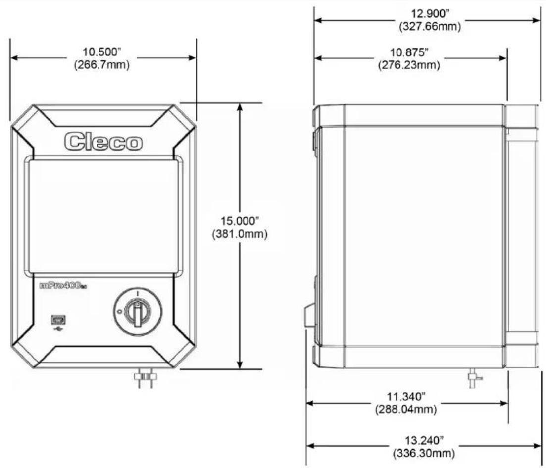
11.1 Dimensions
Dimensions see page 120.
11.2 Ambient conditions
| Features | Data |
| Operation site | Industrial interiors (EMC limit class A) |
| Ambient temperature | 0 °C – 45 °C |
| Storage temperature | -20 °C – 70 °C |
| Type of cooling | Convection (self-cooling) |
| Relative humidity | 10 % – 90 % No Condensation |
| Working height | Up to 3,000 m (9,843 ft) above sea level |
| Degree of protection EN 60529 (IEC 60529) | IP42 |
| Degree of contamination DIN EN IEC 60664-1 | 2 |
| Schock max. EN 60068-2-27 | 15 G |
| Vibration max. EN 60068-2-6 | 59.6 – 160 Hz: 2 G |
11.3 Electrical Data
| Features | Data |
| Supply Voltage, [VAC] | 100 – 240 ± 10 %^2 >200 for High Power Tools ^3 |
| Rated Supply Current [A] | 2 – 1 |
| Frequency [Hz] | 50 – 60 |
| Peak Current [A] | 16 |
| Rated Power [max. VA] | 1600 |
| Idling [W] | 45 |
| Protection ClassEN 61140 | I |
| Transient OvervoltageEN 61010-1 | CAT II |
11.4 Safety Technology
| Safety indices | ||
| Safety indices | STO | Safe start lockout (STO, Safe Torque Off) in accordance with EN 61800-5-2, with SIL 2Safe start lockout (STO, Safe Torque Off) in accordance with EN 61800-5-2, with SIL 2 |
| SIL | SIL 2 | Safety level (Safety Integrity Level) in accordance with EN 61800-5-2 |
| Category | 3 | Classification in the category is in accordance with EN ISO 13849-1 |
| PL | PL d | Performance Level is in accordance with EN ISO 13849-1 |
| DCavg | 60 % | Low, average diagnostic coverage (Average Diagnostic Coverage) |
| HFT | 1 | Hardware Failure Tolerance |
| SFF | >60 % | Safe Failure Fraction |
| PFH | 9,1 E-10 1/h | <0.1 % of SIL 2, Probability of dangerous Failure per Hour |
| PFDav (T=20 a) | 7,9 E-05 | 0.8 % of SIL 2, Probability of dangerous Failure on Demand |
| Test interval [Months] | 12 Maximum time between re-tests for requesting the STO function. | |
| TM [Years] | 20 | Service life according to EN ISO 13849-1 |
| MTTFd | >2.000 a | HIGH, Mean time to dangerous failure |
| Control signals STO-A and STO-B at [X41] and [X42] | |
| Nominal voltage [VDC] | 24 (based on GND_STO) |
| Voltage range [VDC] | 0 – 28.8 |
| Allowed residual ripple [%] | 2 (based on nominal voltage; leaving the voltage range is not allowed) |
| Input current [mA] | 4 (typical for 24 V) |
| Switching threshold On [VDC] | >17 |
| Switching threshold Off [VDC] | <4,5 |
| Switching time On [ms] | <1 |
| Switching time Off [ms] | <1 |
| Auxiliary supply 24 V [X41] | |
| Nominal voltage [VDC] | 24 |
| Nominal current [mA] | 100 (short circuit proof) |
| Feedback contact FB1, FB2 [X41] | |
| Max. voltage [VDC] | <30 |
| Nominal current [A] | 0.5 |
| Resistance [Ω] | <1 (switched on) |
| Residual current [μA] | <2 (switched off) |
11.5 System Data
| Features | Data |
| System Functions | Battery Buffered Real Time Clock, Buffer Time: 10 Years (at 20 °C) |
| Display | LC-Display with Touchscreen 10.4" TFT Liquid Crystal Display Resolution 800x600, Connection To Panel & Touch Possible |
| Features | Data |
| Operating System | OS-9000, Real-Time Operating System, Bootable Without Mechanically Moving Drives, No UPS Required |
| HMI (Human Machine-Interface) | Virtual Keyboard for Alpha-numeric Inputs |
11.6 Weight
| Model | Weight [kg] |
| Controller | 12.7 |
| including mounting plate | 13.8 |
12 Disposal
Components and auxiliary materials of the product pose risks to the health and the environment. The tool contains components that can be recycled as well as components that must be specially disposed of.
▶ Follow the locally applicable regulations.
Separate the components of the packing and segregate the different materials before disposing of them.
Separate the components and dispose of them by segregating them clearly.

Observe generally valid disposal guidelines such as, in Germany, the Electrical and Electronic Equipment Act (ElektroG) and the Battery Act (BattG). Wasted electronic equipment must be disposed of.
▶ Return the defective product to your company collection facility or to Sales & Service Center.
| Revisionsdatum | Revisionsnummer | Name | Beschreibung |
| January, 2024 | D | GGL | General update |
| August, 2025 E | GGL Restriction: | range supply voltage, BD(E) series added | |
X41, X42 – Emergency Stop (STO)
| Date de révision | Ré-vision | Name | Description |
| January, 2024 | D | GGL | General update |
| August, 2025 | E | GGL | Restriction: range supply voltage, BD(E) series added |
Demande de logiciel
Coupure de surcharge
| 修订日期 | 修订编号 | 姓名 | 描述 |
| January, 2024 | D | GGL | General update |
| August, 2025 | E | GGL | Restriction: range supply voltage, BD(E) series added |
软件要求
| Data wersji | Numer wersji | Name | Opis |
| January, 2024 | D | GGL | General update |
| August, 2025 | E | GGL | Restriction: range supply voltage, BD(E) series added |
Fig.: Connection positions
| Pos. | Designation | Max.cable length | Pos. | Designation | Max.cable length |
| X23 | Power supply connection | - | |||
| X1X2 | EthernetRJ45 10/100 BASE-T Connector 1RJ45 10/100 BASE-T Connector 2 | 100 | |||
| X3X4 | USB V2.0 Port 1USB V2.0 Port 2 | 30 | X24* | Tool Connector NeoTek Series30E(...)N(...)50E(...)N(...)70E(...)N(...) | 454526 |
| X5X6 | Serial RS232-1 Connector 1Serial RS232-1 Connector 2 | 30 BD(E) | Series | 1, 2, 3, 4 | 45 |
| X7X8 | Anybus CC – Fieldbus Slot 1Anybus CC – Fieldbus Slot 2 | 30 | X25 | Tool Connector Series18, 48, 67 | 50 |
| X9X10 | I/O Connector 0 – 3I/O Connector 4 – 7 | 30 | X42 | Emergency switch-off OUT | 60 |
| X21 | System Bus ConnectorTSnet OUT | 60 | X41 | Emergency switch-off IN | 60 |
| X22 | System Bus ConnectorARCNET | 100 |
* When using tool Series 70:
- ≤3 m Tool Cable: can be used with a maximum of 25 m Extension Cable.
- ≤6 m Tool Cable: can be used with a maximum of 20 m Extension Cable.
• Tool cables over 6 m must not be extended.
* When using controller Secondary:
• Tool Cable can be used with a maximum of 30 m.
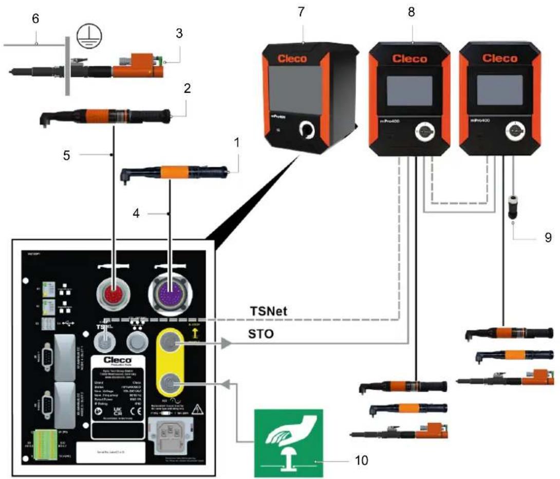
Fig. 8-1: System layout – Order no. see chapter 4 Accessory, page 12
| Pos. | Product | Pos. | Product |
| 1 | Corded handtool: 18, 48, 67 series | 6 | PE cable, grounding mounting plate |
| 2 | Corded handtool: NeoTek series | 7 | mPro400GCD-P-STO |
| 3 | Fixtured spindle: BD(E) series | 8 | mPro400GCD-SH-STO |
| 4 | Tool cable 18, 48, 67 series | 9 | Termination plug STO |
| 5 | Tool cable NeoTek series | 10 | Emergency switch-off device |
Dimensions
Mounting plate for wall mounting (4 x M6 screw)
POWER TOOLS SALES & SERVICE CENTERS
Please note that all locations may not service all products.
Contact the nearest Cleco® Sales & Service Center for the appropriate facility to handle your service requirements.

Sales Center
Service Center
NORTH AMERICA | SOUTH AMERICA
DETROIT, MICHIGAN
Apex Tool Group
2630 Superior Court
Auburn Hills, MI 48236
519 Nurigong Street, Albury
NSW 2640
Australia
Phone: +61 2 6058 0300
CHINA
Apex Power Tool Trading
(Shanghai) Co., Ltd.
2nd Floor, Area C
177 Bi Bo Road
Pu Dong New Area, Shanghai
China 201203 P.R.C.
Phone: +86 21 60880320
Fax: +86 21 60880298
INDIA
Apex Power Tool Trading
Private Limited
Gala No. 1, Plot No. 5
S. No. 234, 235 & 245
Indialand Global
Industrial Park
Taluka-Mulsi, Phase I
Hinjawadi, Pune 411057
Maharashtra, India
Phone: +91 020 66761111
JAPAN
Apex Tool Group Japan
Korin-Kaikan 5F,
3-6-23 Shibakoen, Minato-Ku,
Tokyo 105-0011. JAPAN
Phone: +81-3-6450-1840
Fax: +81-3-6450-1841
KOREA
Apex Tool Group Korea
1503, Hibrand Living Bldg.,
215 Yangjae-dong,
Seocho-gu, Seoul 137-924,
Korea
Phone: +82-2-2155-0250
Fax: +82-2-2155-0252
Cleco
Tame the Line
- Disclaimer
- Trademark
- Apex Tool Group
- Apex Tool Group GmbH
- Content
- EN
- DE
- Validity
- Symbols in the Text
- Safety
- Warnings and Notices
- Danger
- Warning
- Caution
- Note
- Structure Of Warnings
- Symbols on the Product
- Intended Use
- Foreseeable misuse
- Operator Training
- Personal Protective Equipment
- Safety instructions relevant to the system
- Cleco
- Risk of injury due to electric shock
- During installation
- Before commissioning
- During operation
- Danger due to incorrect torque measurement
- Danger due to an unexpected motor start or an expected, but not functioning, stop
- During maintenance
- During cleaning
- Use of the secondary controller
- WARNING!
- Risk of injury due to dangerous movements
- FCC- and ISED Compliance
- FCC Responsible party
- Items Supplied
- Accessory
- Transport
- Product Description
- Pin Assignment
- X5,6 - Additional Devices
- Data loss
- Installation Instructions for Fieldbus Module
- X7, X8 – Anybus Compact Com
- X9, X10 - Digital Inputs/Outputs
- Overload shutdown
- Inputs
- Outputs
- Interruption of power supply
- X24 – Tool Connector Digital
- X25 - Tool Connector Analog
- X41, X42 – Emergency Stop (STO)
- Data Storage
- Initial Operation
- STO Safety Function
- Description
- Safety
- Performance Features
- Diagnostic Coverage (DC)
- Interfaces
- Interface port X41 - IN
- Interface port X42 - OUT
- Control Signals
- Discrepancy time
- Test pulses
- Feedback contact FB
- Overvoltage and polarity reversal protection
- Diagnostics
- STO status signal to control
- Fail-Safe state
- Time response
- Installation
- Shut down of STO safety function X41
- Necessary safety function STO disabled
- Connection X42
- Function Test
- Technical Data
- Dimensions
- Ambient conditions
- Electrical Data
- Safety Technology
- System Data
- Weight
- Disposal
- Coupure de surcharge
- Dimensions
- POWER TOOLS SALES & SERVICE CENTERS
- NORTH AMERICA | SOUTH AMERICA
- DETROIT, MICHIGAN
- CHINA
- INDIA
- JAPAN
- KOREA
- 1503, Hibrand Living Bldg.,
Brand : Cleco
Model : mPro400GCD
Category : Industrial Controller