
FWN12AATN6V3 - Air-conditioner DAIKIN - Free user manual and instructions
Find the device manual for free FWN12AATN6V3 DAIKIN in PDF.

| Brand | Daikin |
| Model | FWN12AATN6V3 |
| Product type | High static pressure fan coil unit |
| Heat transfer fluid | Water |
| Water temperature range | 5 °C to 95 °C |
| Ambient temperature range | -20 °C to 43 °C |
| Supply voltage | 230 V ± 10 % |
| Maximum primary fluid pressure | 10 bar |
| Maximum relative humidity | < 85% without condensation |
| Approximate dimensions (W × D × H) | 1174 × 296 × ? mm (depth not specified) |
| Weight | 67 kg |
| Main functions | Heating and cooling with water, ventilation |
| Fan type | EC motor with built-in inverter |
| Hydraulic connections | Connections for main and additional coil (2 or 4 pipes) |
| Available controls | Electronic control panels (FWTOUCH, FWECSAP, FWEC5, FWEC3A, FWEC10) |
| Available accessories | 2/3-way ON/OFF or modulating valves, electric heaters, air filters, condensation kits, etc. |
| Routine maintenance | Clean the air filter with warm water or compressed air, check condensate |
| Coil cleaning | Compressed air or low-pressure steam without damaging the fins |
| Safety | Use by children ≥ 8 years under supervision, installation by qualified personnel |
| Installation instructions | Horizontal or vertical position, tilt for condensate drainage, maintenance space |
| General information | Designed for ambient air conditioning in civil applications |
Frequently Asked Questions - FWN12AATN6V3 DAIKIN
User questions about FWN12AATN6V3 DAIKIN
0 question about this device. Answer the ones you know or ask your own.
Ask a new question about this device
Download the instructions for your Air-conditioner in PDF format for free! Find your manual FWN12AATN6V3 - DAIKIN and take your electronic device back in hand. On this page are published all the documents necessary for the use of your device. FWN12AATN6V3 by DAIKIN.
USER MANUAL FWN12AATN6V3 DAIKIN
| Ecodesign: Directive 2009/125/EC | |
| Commission regulations: Airconditioning (EU) 2018/228 | |
| 1 and carry with the following standards or other normative documents: 1. and carry with the following standards or other normative documents: 1. and carry with the following standards or other normative documents: 1. and carry with the following standards or other normative documents: 1. and carry with the following standards or other normative documents: 1. and carry with the following standards or other normative documents: 1. and carry with the following standards or other normative documents: 1. and carry with the following standards or other normative documents: 1. and Carry with the following standards or other normative documents: 1. and carry with the following standards or other normative documents: 1. and carry with the following standards or other normative documents: 1. and carry with the following standards or other normative documents: 1. and carry with the following standards or other normative documents: 1. and carry with the following standards or other normative documents: 1. and carry with the following standards or other normative documents: 1. and carry with all documentation form a document form a document form a document form a document form a document form a document form a document form a document form a document form a document form a document form a document form a document form a document form a document form a document form a document form a document form a document form a document form a document form a document form a document form a document form a document form a document form a document form a document form a document form a document form a document form a document form a document form a document from a document from a document from a document from a document from a document from a document from a document from a document from a document from a document from a document from a document from a document from a document from a document from a document from a document from a document from a document from a document from a document from a document from a document from a document from a document from a document from a document from a document from a document from a document from a document from a document from a document froma document froma document froma document froma document froma document froma document froma document froma document froma document froma document froma document froma document froma document froma document froma document froma document froma document froma document froma document froma document froma document froma document froma document froma document froma document froma document froma document froma document froma document froma document froma document froma document froma document froma docjment froma docjment froma docjment froma docjment froma docjment froma docjment froma docjment froma docjment froma docjment froma docjment froma docjment froma docjment froma docjment froma docjment froma docjment froma docjment froma docjment froma docjment froma docjment froma docjment froma docj 1. and carry with the following standards or other normative documents: 1. and carry with the following standards or other normative documents: 1. and carry with the following standards or other normative documents: 1. and carry with the following standards or other normative documents: 1. and carry with the following standards or other normative documents: 1. and carry with the following standards or other normative documents: 1. and carry with the following standards or other normative documents: 1. EN 1397. | |
| RoHS (2011/65/EU) | |
| RoHS (2011/65/EU) | |
| RoHS (2011/65/EU) | |
| RoHS (2011/65/EU) | |
| RoHS (2011/65/EU) | |
| RoHS (2011/65/EU) | |
| RoHS (2011/65/EU) | EN IEC 63000. |
| Notea: | ### |
| ### | ### |
| ### | ### |
| ### | ### |
| ### | ### |
| ### | ### |
| ### | ### |
| ### | ### |
| ### | ### |
| ### | ### |
| ### | ### |
| ### | ### |
| ### | ### |
| ### | ### |
| ### | ### |
| ### | ### |
| ### | ### |
| ### | ### |
9 RICERCA DEI GUASTI 8
10 RATED TECHNICAL DATA 47
WEIGHTS 48
11 FIGURE 49
12 KIT VALVOLE STANDARD 58
13 SCHEMI ELETTRICI 61
FWN 04-07 + FWECSA + valvola on/off 230Vac
FWN 08-10 + FWECSA + valvola on/off 230Vac
FWN 12-18 + FWECSA + valvola on/off 230Vac
9 RICERCA DEI GUASTI
9 TROUBLESHOOTING 15
10 RATED TECHNICAL DATA 47
WEIGHTS 48
11 FIGURES 49
12 STANDARD MODELS KIT VALVE 58
13 FWN ELECTRICAL CONNECTIONS 61
OPERATING LIMITS
Thermal carrier fluid: water
Water temperature: 5^ ÷ 95^
Air temperature: -20^ ÷ 43^
Supply voltage:
V+/- 10%
Maximum primary fluid pressure: 10 bar
Ambient air humidity limit: RH < 85% non-condensing
1 BEFORE STARTING THE INSTALLATION PROCEDURE
TRANSLATION BY ORIGINAL INSTRUCTIONS
Carefully read this manual.
Installation and maintenance should be carried out by technical personnel qualified for this type of machine, in compliance with current safety regulations.
When receiving the unit please check its state verifying if any damage occurred during the transport.
For installation and use of possible accessories please refer to the pertinent technical sheets.
The manual are subject to changes, in any times, without prior notice aimed at improving the product.
Identify the model of the FWN fan coil following the indications on the packing container.
SAFETY SYMBOLS

Carefully read this manual.
Warning

Use personal protective equipment
USE APPROPRIATE PPE (GLOVES, PROTECTIVE GOGGLE)
WARNING: Electrical and electronic products may not be mixed with unsorted household waste. Do NOT try to dismantle the system yourself: the dismantling of the system, treatment of the refrigerant, of oil and of other parts must be done by an authorized installer and must comply with applicable legislation. Units must be treated at a specialized treatment facility for reuse, recycling and recovery. By ensuring this product is disposed of correctly, you will help to prevent potential negative consequences for the environment and human health. For more information, contact your installer or local authority.
DANGER: The unit may be used by children of at least 8 years of age and by persons with reduced physical, sensory, or mental capabilities, or who lack experience or the necessary knowledge, provided that they are supervised or after they have received instructions relating to the safe use of the unit and understand the inherent dangers. Children must not play with the unit. Cleaning and maintenance to be carried out by the user must not be performed by unsupervised children.
ATTENTION: the unit hasn't dangerous components according to the classification of Regulation 1357/2014.
WARNING: unit installation and start-up must be entrusted to competent personnel and performed in a workmanlike manner, in accordance with current regulations.
2 DESCRIPTION AND INTENDED USE
High-head thermal ventilating units available in 9 models.
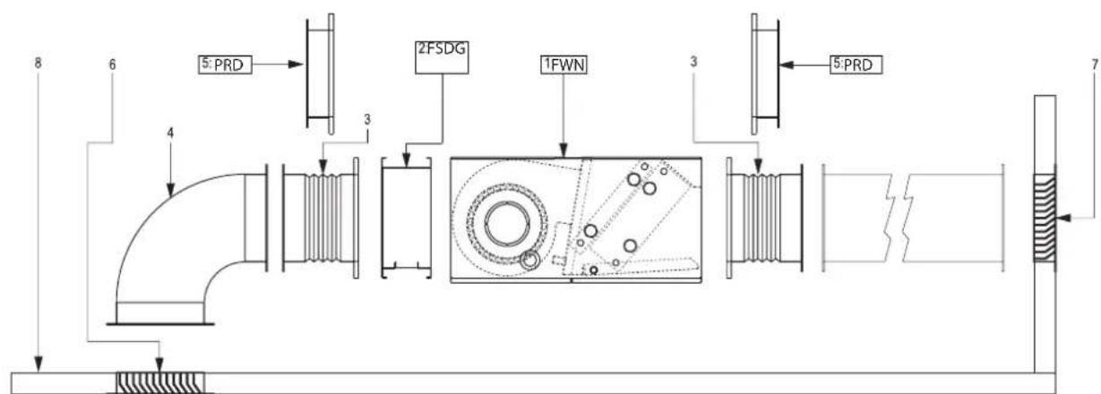
Components description: 1 Unit exploded view p. 49.
DAIKIN will not accept any liability for damage or injury caused as a result of installation by non-qualified personnel; improper use or use in conditions not allowed by the manufacturer; failure to perform the maintenance prescribed in this manual; use of spare parts other than original factory parts.
INSTALLATION SITE
When choosing an installation site, you should observe the following rules:
the device is designed for indoor installations in 'urban' atmosphere, non-marine, non-corrosive and non-dusty;
Equipment designed for ambient air conditioning and intended for use in civil comfort applications.
Do not change the internal wiring or other parts of the equipment. Air sucked by the equipment must always be filtered. Use, when possi
the specific accessories: FSDG. See figure: 4 p. 53
WARNING: during wintertime periods of quiescence, drain water from the system, to prevent ice from forming. If anti-freeze solutions are used, check for their freezing point.
The air conditioning unit should not be placed immediately under a socket;
install in a position where the room can be cooled or heated evenly;
- Do not install the unit in environments with gas or flammable dusts and acid or alkaline substances;
— Do not expose the unit to sprays of water; do not install the unit in laundry room;
Install the fan coil on structural elements able to withstand its weight. Keep a clear space all around the unit to assure the proper
functioning and accessibility for routine and extraordinary maintenance.
- Store the unit in its packing container until you are ready to install it to prevent dust from infiltrating inside it.
Not be overcome the following concentrations of polluting factors in the air environment where the unit is installed:
| SO2 | <0.02 ppm |
| H2S <0.02 ppm | |
| NO, NO2 | <1 ppm |
| NH3 | <6 ppm |
| N2O <0.25 ppm |
WATER QUALITYWARNINGS
NB: is recommended to analyze the water circulating in coil searching for the presence of bacteria (ferrobacteria and micro-organisms that can produce H_2S or chemically reduce sulphates) and
the chemical composition of the water to prevent corrosion and scaling inside the pipes.
The water used to power the circuit can't overcome the levels indicated below:
| Appearance Clear | |
| Odour Odorless | |
| pH | 7.5-107-7.5 only if TOC < 1.5 g/m3 |
| O2 dissolved < 0.1 mg/l | |
| Hardness 60-300 mg/ CaCO | 3 |
| Conductivity 10-500 microS/cm | |
| Carbon dioxide [CO2] < 30 mg/l | |
| Total iron | <0.5 mg/l |
| Nitrates | 0 mg/l |
| Chlorides 200-400 mg/l | |
| Sulphates | < 30 mg/lKCI-1/SO4(2-)< 1 |
3 DIMENSIONS AND TECHNICAL DATA
In figures from page 2 p. 50 and 3 p. 52 show the dimensions of FWN, the position of water connections and installation clearance. Rated technical data are shown in p. 47.
3.1 ACCESSORIES
| Electronic microprocessor control panels with display | FWTSKA | Water sensor for FwEC3A and FwECs controllers | ||
| FWTOUCH | User interface with display in Dibond maternal available in: FWTOUCHB-Black FWTOUCHW-White FWTOUCHG-Grey | FWC5WA | Temperature probe for FwEC10 control | |
| Electrical heating elements | ||||
| FWECSAP | Circuit board for FwECS control | EDEH | Heating element with installation kit, relay box and safety devices | |
| FWECSAC | User interface with display for FwECS controller | |||
| Accessories | ||||
| FWEC3A | FWEC3A Microprocessor control with display | CDRP1A | Condensate drainage pump kit | |
| FWFCKA | FWEC3A control spacer for wall mounting | EDDP | Auxiliary water drip tray | |
| FWEC10 | Electronic controller FwEC10 for EC fans and 1 or 2 ON/OFF 230V valves control | |||
| FWHSKA | Humidity sensor for FwEC3A, FwEC5 | FWTSKA | FWTSKA | |
| EDMFA Motorised fresh air intake louvre | |
| PCIC | Panels with circular collars for the distribution of the air by means of hoses |
| PRD | Panels with flanged sleeves for the connection to rectangular ducts |
| Filter | |
| FSDG***A Air filter G4 | |
| Valves | |
| 2-way valves, ON/OFF or MODULATING actuator, 230 V or 24 V power supply, hydraulic kit, for additional heat exchanger | |
| 2-way valve, ON/OFF or MODULATING actuator, 230 V or 24 V power supply, hydraulic kit, for main heat exchanger | |
| 3-way valves, ON/OFF or MODULATING actuator, 230 V or 24 V power supply, hydraulic kit, for additional heat exchanger | |
| 3-way valves, ON/OFF or MODULATING actuator, 230 V or 24 V power supply, hydraulic kit, for main heat exchanger | |
| 2-way valves pressure independent, ON/OFF actuator, 230 V power supply, hydraulic kit, for main and additional heat exchanger | |
4 INSTALLATION REQUIREMENTS
WARNING: the unit installation and start-up must be entrusted to competent personnel and performed in a workmanlike manner, in accordance with current regulations.
WARNING: It is advisable to install any accessories on the standard equipment, before positioning it, referring to the technical sheets.
WARNING: Thermal ventilating and conditioning FWN unit may be installed horizontal as in vertical configuration. Make sure that the desired configuration is corrected and matches with one of the figure 7 p.55. Configuration AA and AB are both suitable for heating and cooling operation.
WARNING: The units are always supplied in AA configuration, but the air intake position may be changed during the installation. If the installation differs from the supply terms, the layout must be changed by dismantling the unit. (See figure 1 p.49)
Warning for ducted units:
The unit must be installed on the basis of design and technical considerations, carrying out an aeraulic assessment and considering the BACK PRESSURE offered by the PILING applied to the outlet to avoid the problem of failure to change speed: this responsibility cannot fall on the product but on the installation;
Install the unit with the appropriate inspection hatches for routine and special maintenance of the fan coils: for mechanical, electrical and hydraulic replacement;
WARNING: First installation ensure that:
5 INSTALLATION
The sections of the intake and delivery pipes are rectangular, drilled with holes for fixing the available accessories. A round pre-sheared element ( 100mm) is present on both side panels of the unit for the direct inlet of the external air.
To implement the rectangular-section channel-type connection use accessory PRD, which may be fit either at intake or at delivery. 2 PRD accessory panels are required for implementing the intake and delivery with channels. See figure 5 p. 54.
To implement the flexible tube-type connection, use accessory PCIC, which is fitted directly on the machine's intake inlets, by means of drilling. 2 PCIC accessory panels are required for implementing the intake and delivery with flexible tubes. See figure 6 p.54.
- The place of installation has sufficient space for containing the device and for performing installation and maintenance. See figure 2-3 p.50 and p.52.
- The air inlet and delivery are not obstructed.
- The hydraulic connections are positioned and dimensioned as requested by the device. See figure 2-3 from p.50 and p.52.
- The electric power supply line has the features requested on the fan coil's data plate.
WARNING: Install the unit, circuit breaker (IL) and/or any remote controls in a place out of reach of persons who may be taking a bath or shower.
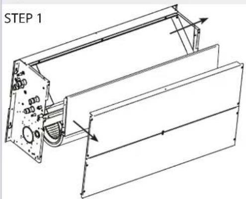
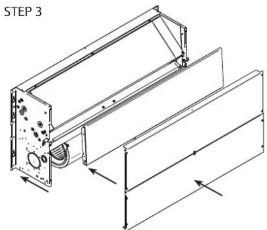
The exchanger connections can be switched over to the opposite side, is recommended to do this before installation, by carrying out the following steps (figure 12 p.57):
remove the upper and lower closing panels.
remove the condensate tank for the horizontal installation.
loosen the 4 fixing screws of the motor support, without unscrewing them all the way.
remove the heat exchanger by unscrewing the 4 fastening screws.
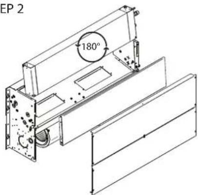
turn the heat exchanger by 180^ (vertical axis), eliminate the presheared elements on the opposite side panel, reinsert the heat exchanger on the unit.
reassemble the previously listed components.
stop the outlet holes of the previously used manifolds with anticon-densing insulating material.
Some rules to follow:
—Vent air from the exchanger while the pumps are off. For this purpose use the air vent valves situated next to the exchanger connections.
- When implementing a channel-type system, it is advisable to place the vibrationdamping joints (available as accessory GA) between the channeling and the unit.
If you wish to install an electrical resistance module (KER) as accessory, the delivery vibration-damping joint should be heat-resistant (accessory GA-T).
All ducts, especially the outlet ducts, must be insulated with anti-condensation material.
An inspection panel must be provided in proximity to the unit to enable maintenance and cleaning operations.
Install the control panel on the wall; choose an accessible position from where functions may be easily set and which is suitable for taking temperature readings, where applicable. Avoid positions directly exposed to sunlight or direct currents of hot or cold air and make sure there are no obstacles which may preclude a correct temperature reading.
WARNING:
In normal operation, particularly with the fan at minimum speed and ambient air with high relative humidity, condensation may form on the air outlet and on some external parts of the unit.
To avoid such issues while always remaining within the operating limits envisaged for the unit, it is necessary to limit the inlet temperature of the water inside the heat exchanger. In particular, the difference between the air dew point (TA,DP) and the inlet water temperature (Tw) must NOT exceed 14^ , according to the following relationship: TW>TA,DP-14°C
Example: in the case of ambient air at 25^ with 75% relative humidity, the dew point temperature is about 20^ and therefore the inlet temperature of the water in the battery must be greater then:
- 20 - 14 = 6^ in order to avoid condensation on a fanoil equipped with a valve.
20-12 = 8 °C If the valve kit accessory can not be installed.
| Fan coil with valve | ||||||
| Relative humidity % | Air temperature dry bulb (°C) | |||||
| 21 23 | 25 27 | 29 31 33 | ||||
| 40 55 55 55 | ||||||
| 50 55 55 56 8 | ||||||
| 60 55 55 57 9 11 | ||||||
| 70 55 68 9 11 13 | ||||||
| 80 56 8 10 12 14 16 | ||||||
| 90 68 10 12 14 16 18 | ||||||
| Fan coil with valve | |||||||
| Relative Humidity % | Air temperature dry bulb (°C) | ||||||
| 21 23 | 27 29 31 | 33 | |||||
| 406666666 | 6 | ||||||
| 50666668 | 10 | ||||||
| 60666791 | 13 | ||||||
| 70668101 | 13 15 | ||||||
| 80681012 | 12 16 18 | ||||||
| 908101214 | 14 18 20 | ||||||
In the event the indoor unit is stopped for a prolonged period, with the fan stopped and circulation of cold water in the heat exchanger, condensation may also form on the unit's exterior. In this case it is advisable to install the 3-way (or 2-way) valve accessory in order to stop the flow of water in the coil when the fan is stopped.
During wintertime periods of quiescence, drain water from the system, to prevent ice from forming. If anti-freeze solutions are used, check for their freezing point using the table below.
| % Glycol by weight | Freezing temperature (℃) | Capacity adjustment | Pressure drop adjustment |
| 0.01,001,00 | |||
| 10 | -4 | 0.971,05 | |
| 20 | -10 | 0.921,10 | |
| 30 | -16 | 0.871,15 | |
| 40 | -24 | 0.821,20 |
5.1 ASSEMBLY OF UNITS
Fix the standard unit to the ceiling or wall using at least 4 of the 6 slots; For horizontal installations (ceiling-mounting) it is advisable to use 8MA threaded bars, screw anchors suitable for the machine's weight, and to arrange for the positioning of the machine using 2
8MA bolts and a washer the diameter of which is suitable for inserting the slot and for then fixing the unit.
Before tightening the check nut, adjust the closing of the main nut so that the equipment will slant correctly, i.e. for facilitating the discharging of the condensate.
In case of wall installation, to favour the drainage of condensate, the drain hose should be inclined downward, at least 3 / 5mm provide for the correct drainage of the condensate drain pipe according to need. The two condensate discharge tubes of the main tank are located inside the side panels and may be accessed through a membrane type raceway that should be etched for passing the discharge tube through it. It is advisable not to remove the aforesaid raceway because it prevents the sharp edge of the hole on the side panel from damaging the condensate discharge tube over time.
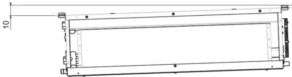
In case of ceiling installation, in particular when the EDDPH accessory is present, install the unit with a slight slope (10 mm), in order to facilitate the condensate drainage. (See figure 10 p. 56). The condensate discharge could be on left side or right side, at the choice of the installer. Slope towards the chosen side, then close the unused side with the cap and place the pipette on the side of the chosen drain, see dimensional drawings p. 50 and p. 52.
Make the plumbing connections to the heat exchanger and, where the cooling function is to be used, to the condensate drainage outlet.
- To connect the unit to the drainage line, use a flexible rubber hose and secure it to the pre-selected drain pipe (Ø 3/8") using a metal clamp (use the drain outlet situated on the plumbing connection side).
To assist the draining of the condensate, slant the discharge tube downwardsby at least 30mm / m making sure that its entire route is clear and free from bends or blockages.
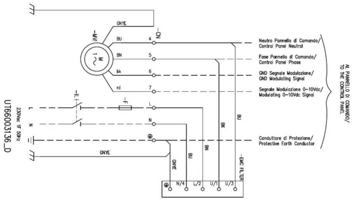
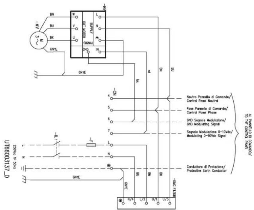
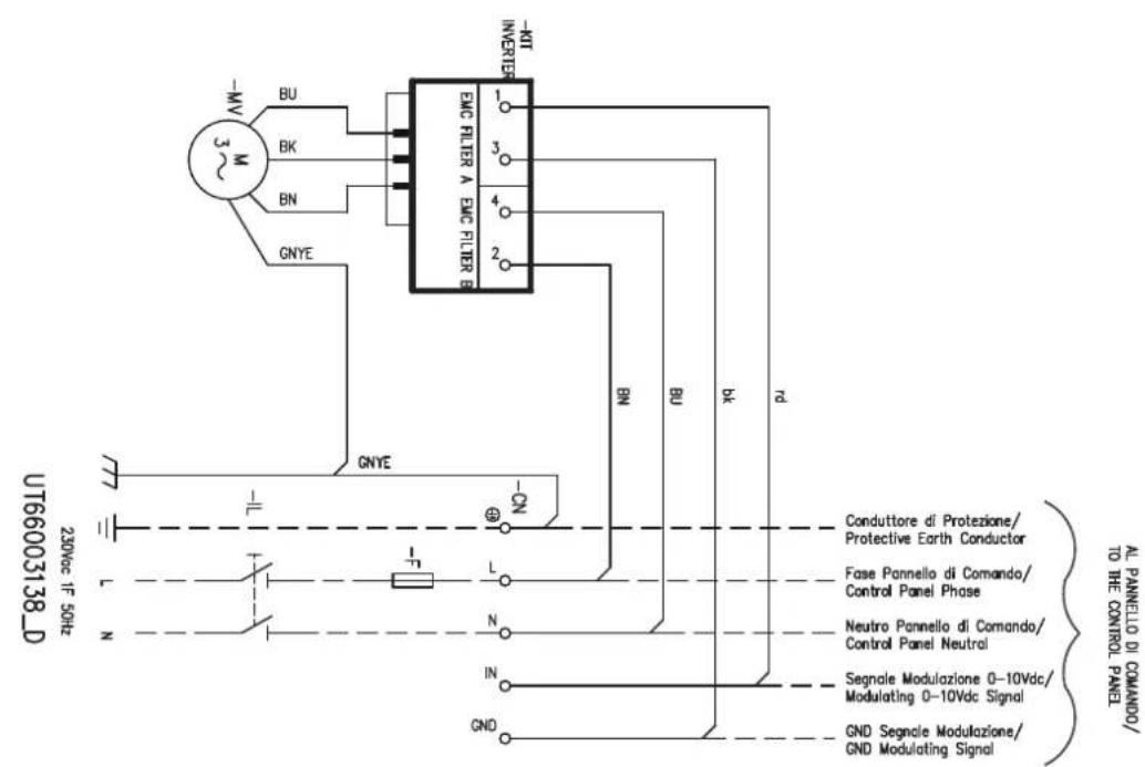
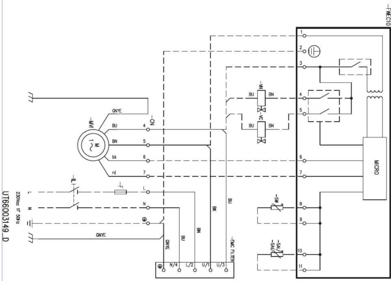
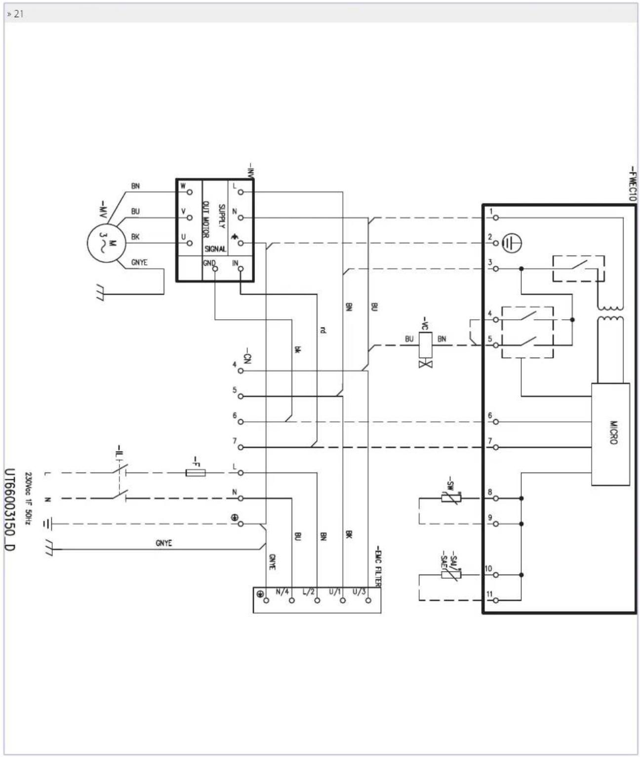
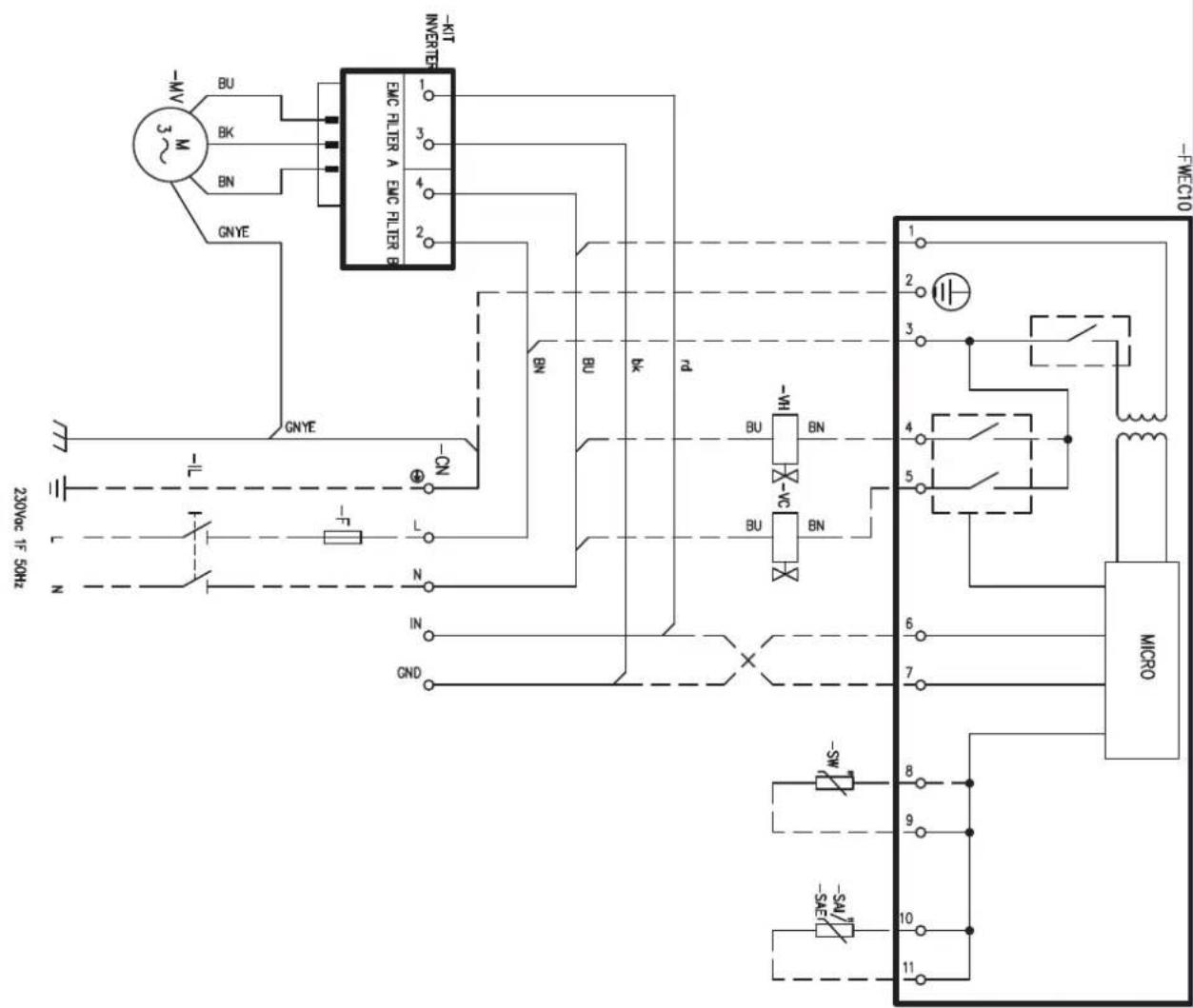
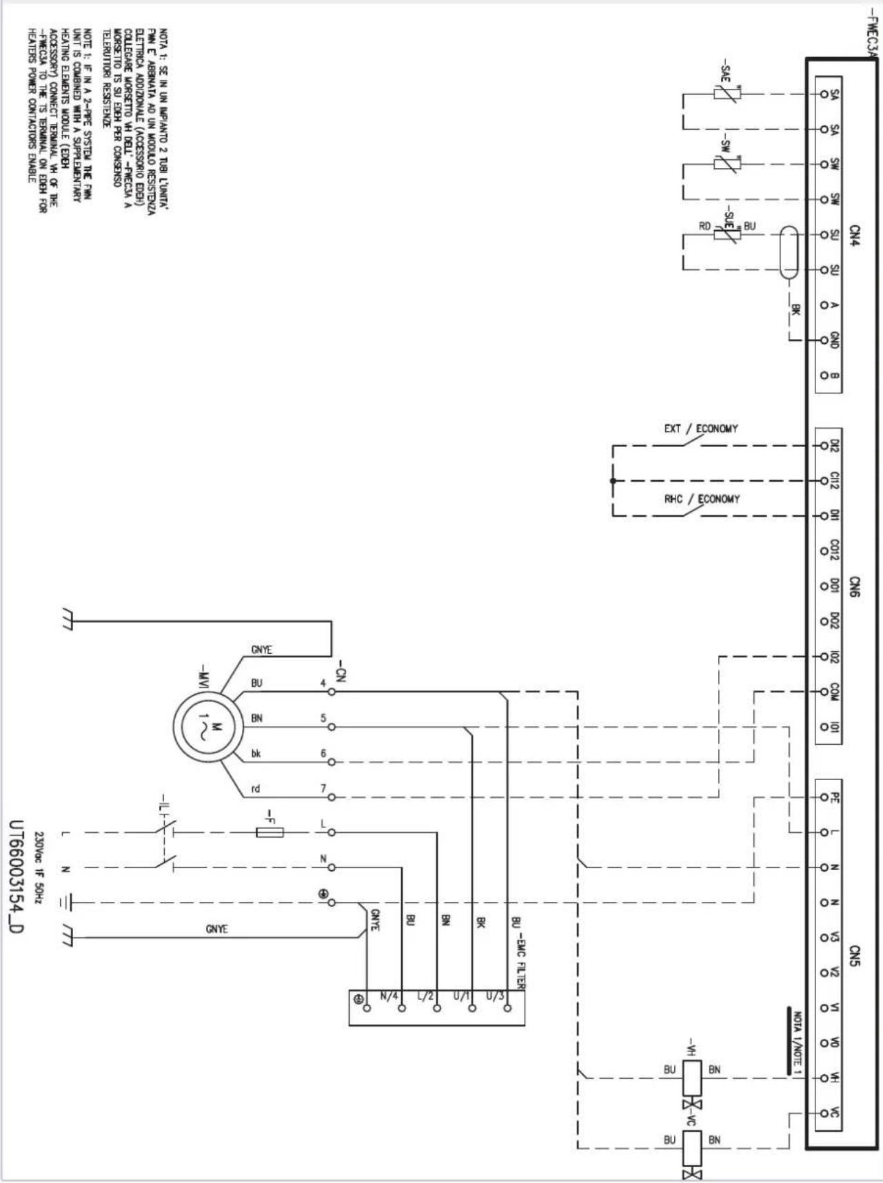
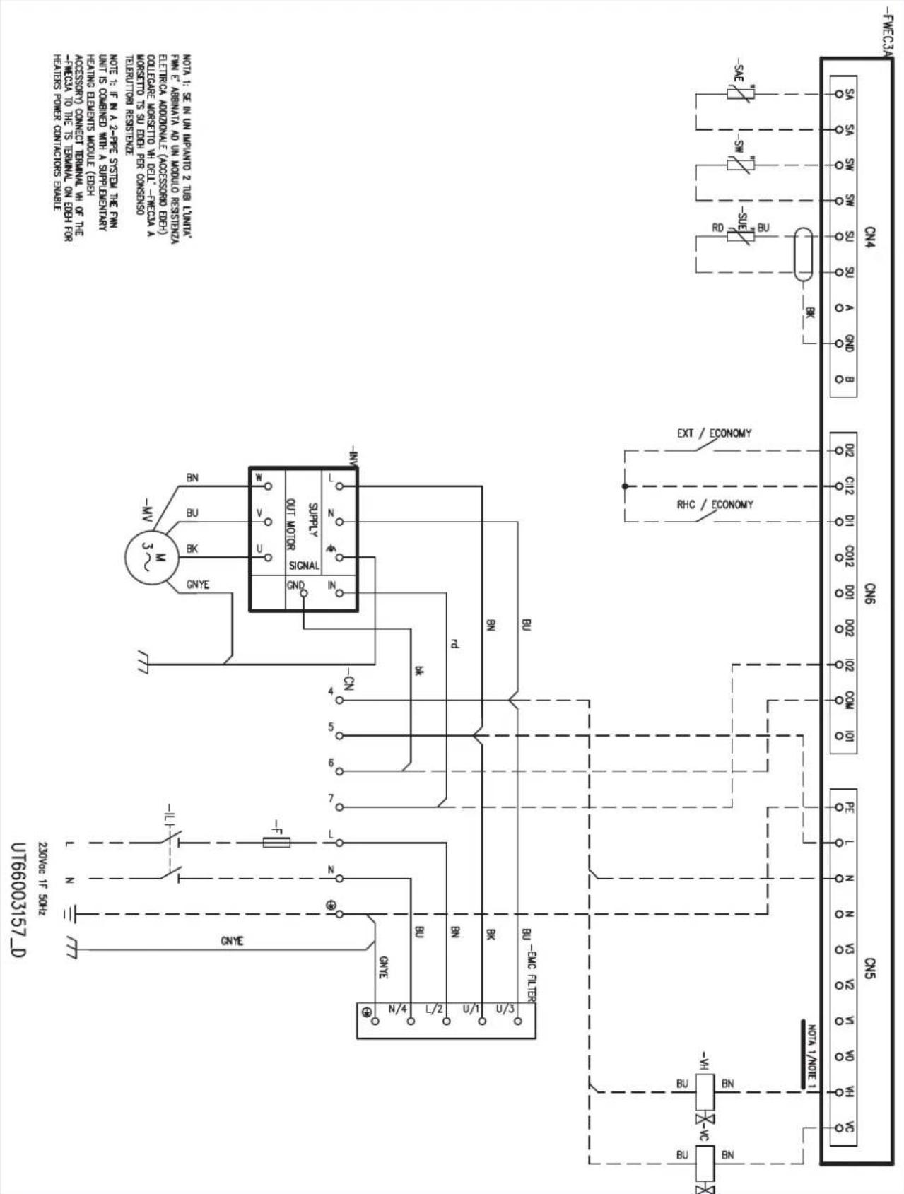
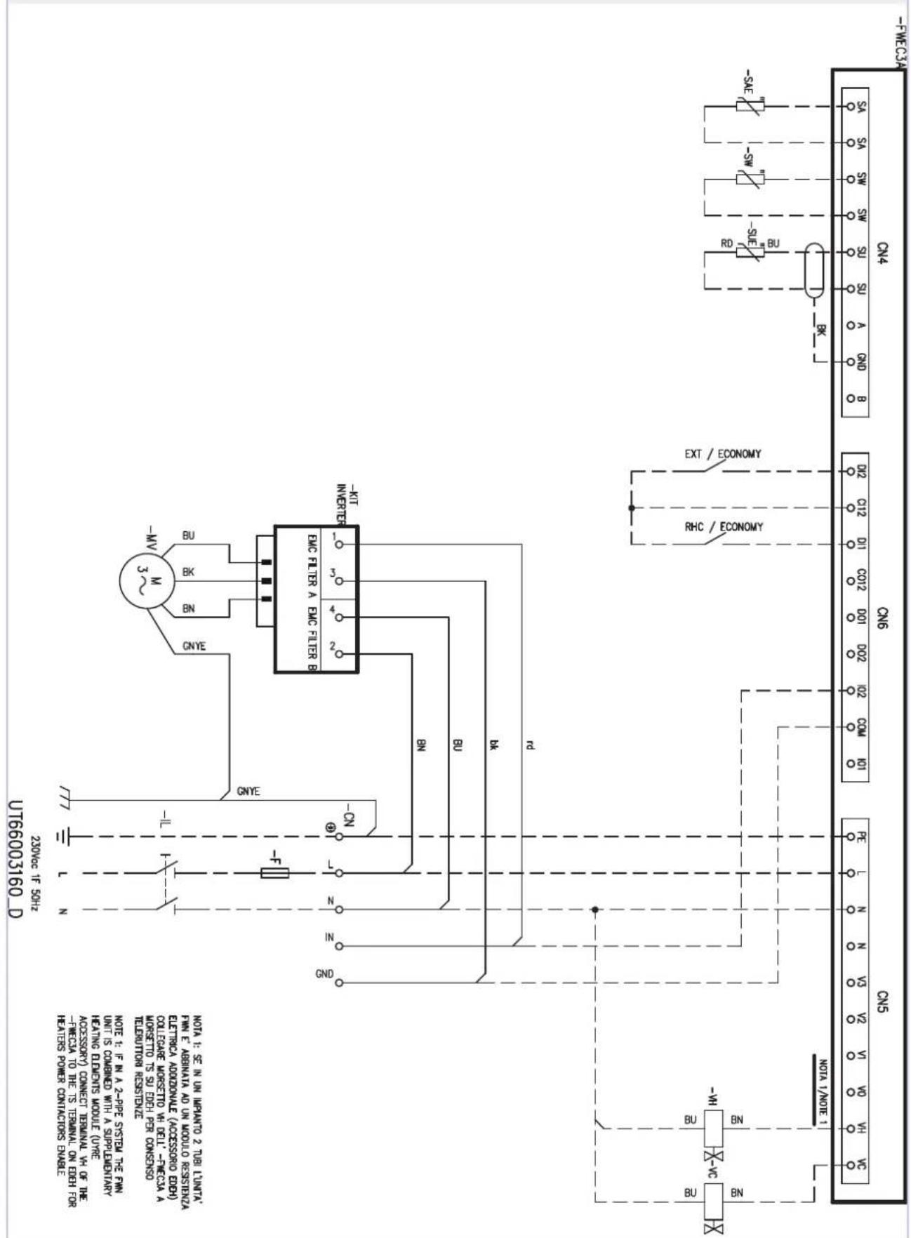
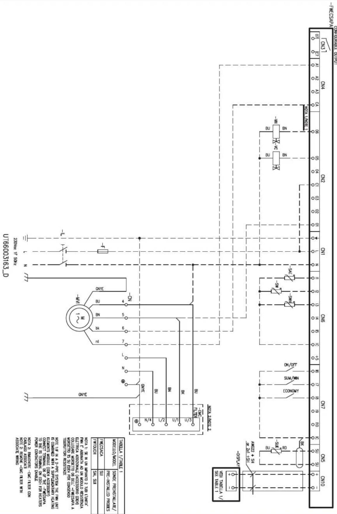
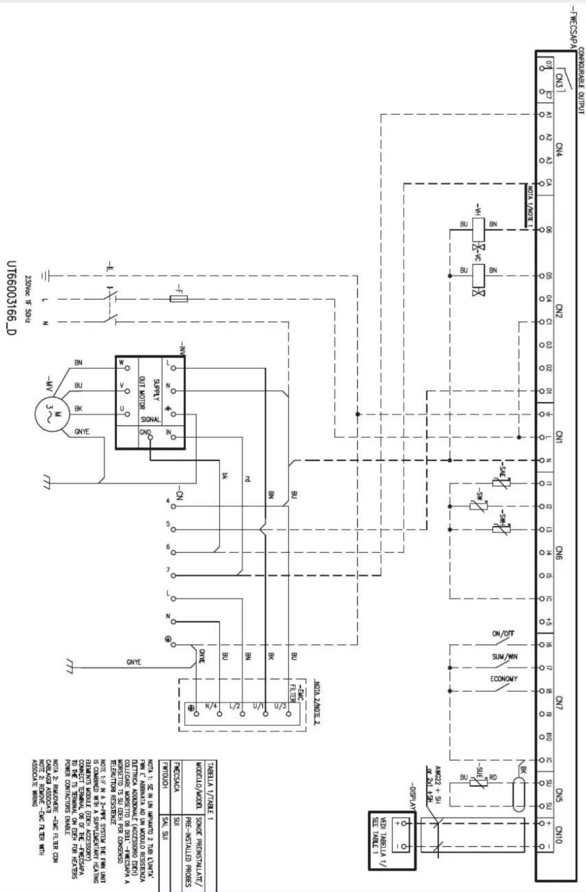
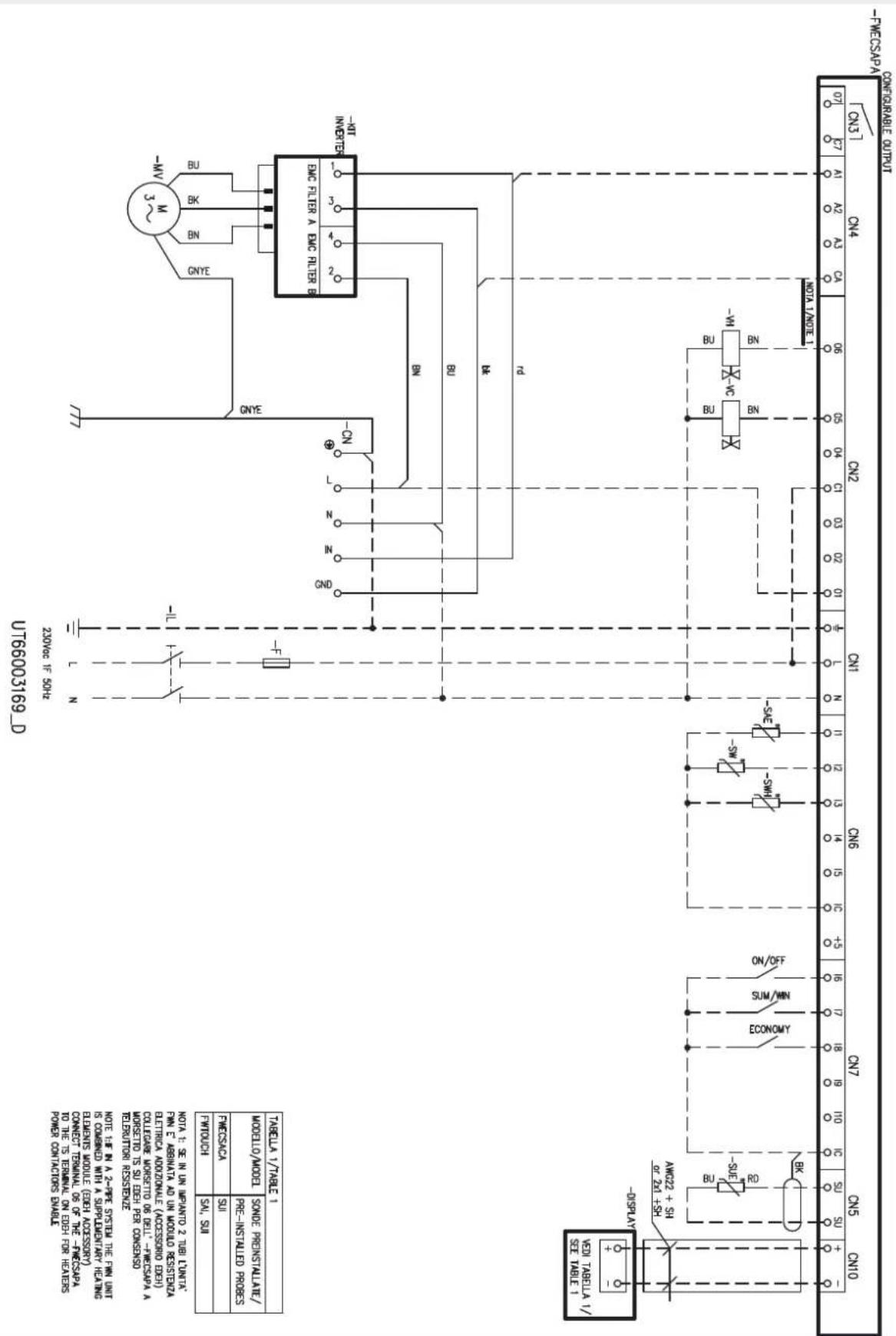
5.2 ELECTRICAL WIRING DIAGRAM LEGEND
IL: Circuit breaker (not supplied)
F: Safety fuse (non supplied)
—CN:Fast on/screw terminal board
— MVI: Fan motor + built-in inverter
—MV: Fan motor
INV: Inverter fan motor
INVERTER KIT: Inverter kit with filter groups
EMC FILTER: EMI/RFI noise filter
BN (L2): Brown = phase filter IN
— BU (N4); Blue = filter IN neutral
BK (U1): Black = filter OUT phase
BU (U3): Blue = filter OUT neutral
-VC: 230Vac ON/OFF cold/hot water valve (2 pipes system) (accessory)
230Vac ON/OFF cold water valve (4 pipes system) (accessory)
— VH: 230Vac hot water valve 4 pipes system (accessory)
SAI: Pre-installed internal air temperature probe
SAE: Remote air temperature probe (accessory)
SW: Remote air temperature probe (accessory)
— SWH: Hot water temperature probe additional coil for 4-pipe units. (accessory - available in option only with SW)
SUI: Pre-installed internal air relative humidity probe
SUE: Remote relative humidity probe (accessory)
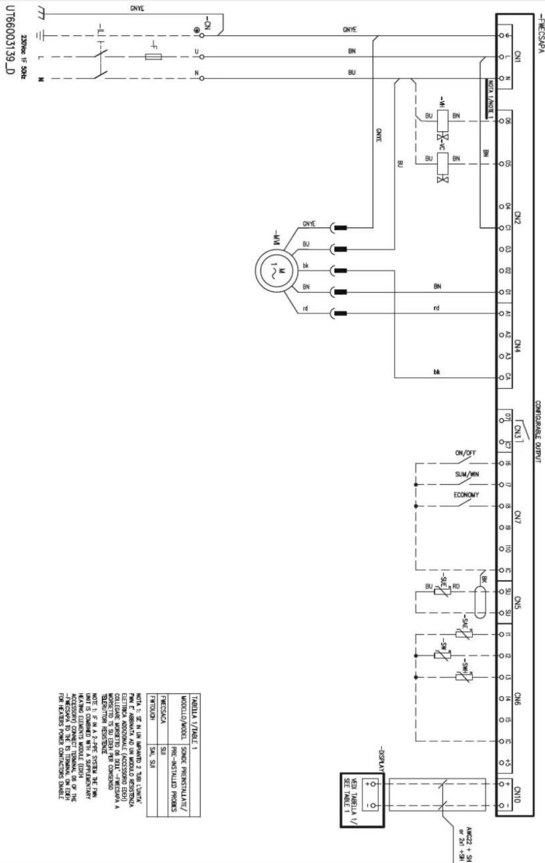
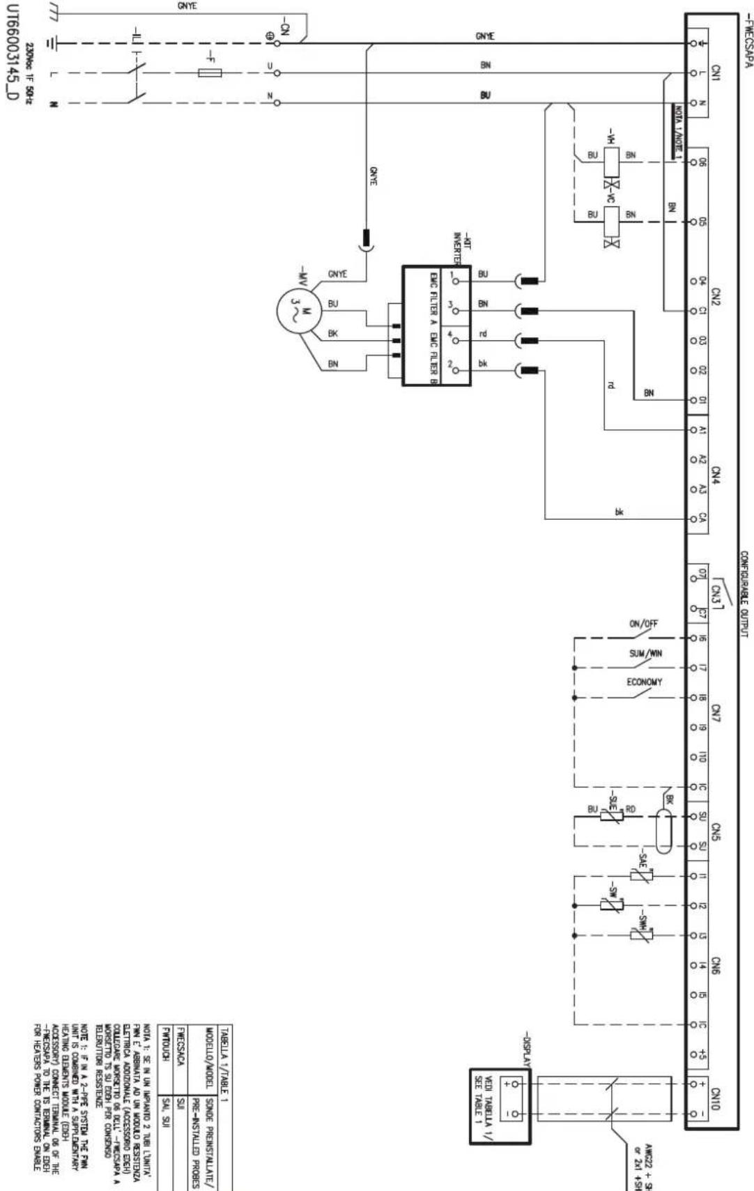
FWECSAPA control electrical wiring diagram legend
T1: Transformer 230Vac/24Vac (not supplied)
5.3 ELECTRICAL CONNECTIONS
Make the electrical connections with the power supply disconnected, in accordance with current safety regulations.
All the wiring must be done by qualified personnel.
For each thermal ventilating unit provide a main circuit breaker (IL), with opening contacts separated by at least 3mm and an adequate protection fuse (F).
Electrical intakes are shown on the rating labels on the units.
In order to make the electrical connections you must remove the lower closing panel (figure 1 p.49) to access the fast-on terminal strip.
NOTE: The electric wires (power and control circuits) must be pulled in through the gland on the side of the electric box where
the plumbing connections are located and then connected to the terminals.
WARNING: COMMON motor wire = WHITE, wrong connection may cause serious damages to the motor.
Base electrical wiring diagrams p.61:
FWN 04-07
FWN 08-10
FWN 12-18
FWN electrical wiring diagrams with FWECSAPA factory mounted p.63:
FWN 04-07 + FWECSA + on/off valve 230Vac
FWN 08-10 + FWECSA + on/off valve 230Vac
FWN 12-18 + FWECSA + on/off valve 230Vac
Electronic controls PC (remote) electrical wiring diagrams on FWN p.66:
FWEC10 on FWN (04-07/08-10/12-18) 2/4 pipe
FWEC3A on FWN (04-07/08-10/12-18) + on/off valve 230 Vac
FWECSAPA on FWN (04-07/08-10/12-18) + on/off valve 230 Vac
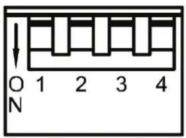
5.3.1 Characteristic of inverter control
The requested curve set point can be carried out at the factory (and amended on site if necessary) by setting the dip switches, as in the diagram below:
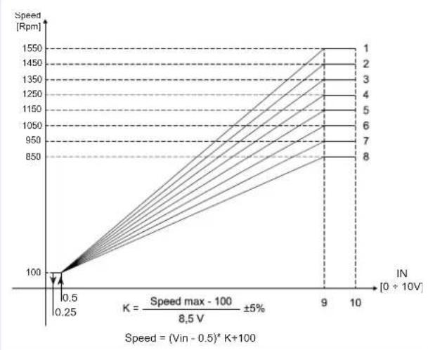
| N° | Maximum speed DIP 1 | DIP 2 | DIP 3 | DIP 4 | ||
| 1 | 150 rpm OFF OFF - | |||||
| 2 | 150 rpm ON OFF OFF - | |||||
| 3 | 150 rpm OFF ON OFF - | |||||
| 4 | 150 rpm ON ON OFF - | |||||
| 5 | 150 rpm OFF ON ON - | |||||
| 6 | 150 rpm ON OFF ON - | |||||
| 7 | 950 rpm | OFF ON ON - | ||||
| 8 | 850 rpm | ON ON ON - |
Note: the maximum speed (1550 rpm) isn't usually used.
NOTE: FWN 04-07 models are equipped with a motor with integrated inverter, the higher models are equipped with an inverter separate from the fan motor unit.
5.4 CHECKS BEFORE STARTUP
- Check that the unit is installed in such a way as to guarantee the required inclination.
- Check that the drainage outlet is not clogged (by masonry debris etc.).
- Check the tightness of the plumbing connections.
Make sure the electric wires are tightly connected (carry out this check with the power supply OFF).
Make sure that air has been eliminated from the heat exchanger.
Power the fan coil and check its performance
6 EXAMPLE OF INSTALLATION
For installation by channels see figure 8 p.55.
7 USE
To use the fan coil refer to the instructions on the on board or remote control panel.
ATTENZIONE: For safety reason, do not introduce your fingers or other pointed objects in the air outlet grilles.
DANGER: The unit may be used by children of at least 8 years of age and by persons with reduced physical, sensory, or mental
8 MAINTENANCE
For installation by flexible ducts see figure 9 p.56.
capabilities, or who lack experience or the necessary knowledge, provided that they are supervised or after they have received instructions relating to the safe use of the unit and understand the inherent dangers. Children must not play with the unit. Cleaning and maintenance to be carried out by the user must not be performed by unsupervised children.
ATTENTION: The maintenance operations must be done by autorized service centre or by qualified personnel.
WARNING: Cleaning and maintenance to be carried out by the user must not be performed by unsupervised children.
DANGER! Due caution must be taken while carrying out maintenance: some metal parts may cause injuries; wear protective gloves.
WARNING: For safety reasons, before carrying out any maintenance or cleaning jobs, turn off the unit by moving the fan speed selector to "Off" and putting off the main switch (0 position).
Fan coils do not have particular maintenance requirements: it is sufficient to periodically clean the air filter.
A running in period of 100 hours is necessary to eliminate all initial mechanical friction of the motor.
Start-up should be carried out at the maximum operating speed.
To assure that the fan coil units perform efficiently, abide by the following indications:
keep the air filter clean
do not pour liquids inside the equipment;
do not introduce metal parts through the air outlet grill;
avoid obstructing the air outlet or intake
Whenever starting up the unit after it has not been used for a long time, check that there is no air in the heat exchanger.
Before the period of operation in the cooling mode, check that condensate is properly drained and that the heat exchanger fins are not obstructed by impurities.
Clean as necessary using compressed air or low pressure steam, taking care not to damage the fins.
Adequate periodic maintenance will ensure save both energy and cost savings.
CLEANING THE AIR FILTER
Disconnect the unit from the power supply by setting the main switch on 0 (OFF).
To clean the air filter proceed as follows:
-
When using standard or FSDG filtering modules, access the equipment through the inspection panel and remove the air filter. (See figure 11 p.57)
-
Clean the filter with warm water or, in the event of dry dust build-up, using compressed air.
- Allow the filter to dry and then fit it back in place.
- It is recommended to replace the air filter once a year, using an original replacement filter; the indoor unit model is specified on the identification plate on the inside of the side panel.
CLEANING THE HEAT EXCHANGER
It It is advisable to check the condition of the exchanger before the start of every summer season to make sure that the fins are not obstructed by dirt.
To access the heat exchanger, remove the outlet panel (whether of the type with collars or a rectangular flange), upper closing panel and the drip tray.
On reaching the exchanger, clean it with compressed air or low-pressure steam taking care not to damage the fins.
Before the start of every summer season, check the efficiency of condensate drainage.
Adequate periodic maintenance will ensure save both energy and cost savings.
9 TROUBLESHOOTING
If the unit is not working properly, before calling a service engineer carry out the checks indicated in the table below.
If the problem cannot be solved, contact your dealer or the nearest service centre.
| PROBLEM CAUSE SOLUTION | ||
| The unit fails to work | No power supply Restore the power supply | |
| The automatic safety cutout has tripped Call a service centre for assistance | ||
| The on/off switch is on Start the unit by moving the switch to I | ||
| The unit provides insufficient cooling or heating | The air filter is dirty or clogged Clean the air filter | |
| An obstacle is obstructing the air intake or outlet Remove the obstacle | ||
| Air is trapped inside the heat exchanger Call the installer for assistance | ||
| There are open windows and/or doors Close windows and/or doors | ||
| The minimum speed has been selected | Select medium or maximum speed | |
| The unit "leaks" water | The unit has not been installed with the correct inclination | Call the installer for assistance |
| The drainage outlet is clogged | Call the installer for assistance | |
1 AVANT DE COMMENCER L'INSTALLATION 18
2 DESCRIPTION ET UTILISATION PREVUE 18
LIEU D'INSTALLATION 18
AVERTISSEMENTS PUR QUALITE DE L'EAU 19
3 DONNÉES DIMENSIONNELLES ET TECHNIQUES 19
4 AVENTISSEMENTS POUR L'INSTALLATION 19
5 INSTALLATION 20
5.1 MONTAGE DE L'UNITÉ 20
5.2 LEGENDES SCHEMAS ELECTRIQUES 21
5.3 BRANCHEMENTS ELECTRIQUES 21
5.4 VERIFICATION FONCTIONNELLE 21
6 EXAMPLES D'INSTALLATION 22
7 UTILISATION 22
8ENTRETIEN 22
NETTOYAGE DU FILTRE A AIR 22
NETTOAYAGE DE LA BATTERIE D'ÉCHANGE THERMIQUE 22
9 RECHERCHE DES CAUSES D'ANOMALIE 22
10 RATED TECHNICAL DATA 47
POIDS. 48
11 FIGURES 49
12 KIT VANNE MODELESTANDARD 58
13 SCHEMAS ELECTRIQUES 61
LIMITES DE FONCTIONNEMENT
Lire attentivement le present manuel.
FWN 04-07 + FWECSA + vanne on/off 230Vac
FWN 08-10 + FWECSA + vanne on/off 230Vac
FWN 12-18 + FWECSA + vanne on/off 230Vac
BN (L2): Braun = phase IN Filter
BU (N4): Blau = Neutralleiter IN Filter
BK (U1): Schwarz = phase OUT Filter
BU (U3): Blau = Neutralleiter OUT Filter
VC: Kalt-/Warmwasser ON/OFF-Ventil 230Vac 2-Leiter-System (Zubehor)
Basic Stromanschlüsse abb.61:
FWN 04-07
FWN 08-10
FWN 12-18
FWN 04-07 + FWECSA + on/off ventil 230Vac
FWN 08-10 + FWECSA + on/off ventil 230Vac
FWN 12-18 + FWECSA + on/off ventil 230Vac
FWN 04-07 + FWECSA + valv. on/off 230Vac
FWN 08-10 + FWECSA + valv. on/off 230Vac
FWN 12-18 + FWECSA + valv. on/off 230Vac
Conexiones electricas Comando electronicos PC (remoto) SU FWN p.66:
FWEC10 su FWN(04-07/08-10/12-18) 2/4 tubos
FWEC3A su FWN(04-07/08-10/12-18) +valv.ON/OFF 230Vac
FWECSAPA su FWN(04-07/08-10/12-18) +valv.ON/OFF 230Vac
5.3.1 Caracteristicas de regulacion del invorsor
» Rated technical data FWN 2 pipes
(1) Water temperature 7^ / 12^ air temperature dry bulb 27^ wet bulb 19^ (47%) relative humidity according to EN1397:2021
(2) Water temperature 45°C / 740°C, air temperature 20°C
(3)Sound power measured according to standards ISO 3741 and ISO 3742
EUROVENTeRifieddata
Power supply 230150(VphHz)
» Rated technical data FWN 4 pipes
| FWN 04 05 06 07 08 | |||||||||||||||||||
| Speed min med max min med max min med max min med max min med max | |||||||||||||||||||
| Control voltage DF 1R (E) V 6,007,408,906,007,408,907,308,008,807,808,90 | |||||||||||||||||||
| Rated air flow DF (E)m2/h 531 694 793 529 686 783 1005 1115 | |||||||||||||||||||
| Available static pressure DF | (E) | Pa | 29 | 50 | 65 | 30 | 50 | 65 | 41 | 50 | 59 | 41 | 50 | 59 | 38 | 50 | 61 | ||
| Total cooling capacity DF | (1)(E) | kW | 2,82 | 3,44 | 3,76 | 3,36 | 4,17 | 4,61 | 5,17 | 5,58 | 5,91 | 5,71 | 6,17 | 6,55 | 6,14 | 6,75 | 7,46 | ||
| Sensible cooling capacity DF | (1)(E) | kW | 2,18 | 2,68 | 2,95 | 2,52 | 3,17 | 3,53 | 3,84 | 4,15 | 4,39 | 4,30 | 4,66 | 4,97 | 4,96 | 5,52 | 6,19 | ||
| Water flow DF | (1)(E) | l/h | 486 | 592 | 647 | 579 | 718 | 794 | 890 | 961 | 1018 | 983 | 1062 | 1128 | 1057 | 1162 | 1285 | ||
| Water pressure drop DF | (1)(E) | kPa | 10 | 14 | 17 | 8 | 12 | 14 | 18 | 21 | 23 | 15 | 17 | 19 | 16 | 19 | 23 | ||
| FCEER class DF | (E) | C | B | C | C | C | |||||||||||||
| Heating capacity DF | (2)(E) | kW | 3,23 | 3,68 | 3,91 | 3,23 | 3,66 | 3,89 | 5,25 | 5,51 | 5,72 | 5,21 | 5,45 | 5,65 | 7,02 | 7,47 | 7,99 | ||
| Water flow DF | (2) | l/h | 278 | 317 | 337 | 278 | 315 | 355 | 452 | 474 | 492 | 449 | 469 | 486 | 604 | 643 | 688 | ||
| Water pressure drop DF | (2)(E) | kPa | 5 | 6 | 7 | 5 | 6 | 7 | 12 | 13 | 14 | 10 | 11 | 12 | 22 | 24 | 27 | ||
| FCCOP class DF | (E) | B | B | C | B | C | |||||||||||||
| Additional coil DF - number of rows | 1 | 1 | 1 | 1 | 1 | ||||||||||||||
| Water connections - additional coil DF | " | 0,75 | 0,75 | 0,75 | 0,75 | 0,75 | |||||||||||||
| Water content - additional coil DF | dm3 | 0,93 | 0,93 | 1,05 | 1,05 | 1,17 | |||||||||||||
| Maximum current absorption | A | 1,83 | 1,83 | 3,52 | 3,52 | 3,52 | |||||||||||||
| Power input DF | (E) | W | 45 | 73 | 112 | 40 | 73 | 112 | 102 | 125 | 152 | 102 | 125 | 152 | 124 | 170 | 248 | ||
| Total sound power level DF | (3) | dB(A) | 54 | 61 | 66 | 54 | 61 | 66 | 59 | 63 | 69 | 61 | 64 | 69 | 62 | 67 | 72 | ||
| Inlet + radiated sound power level DF | (3)(E) | dB(A) | 52 | 59 | 64 | 52 | 59 | 64 | 56 | 60 | 66 | 56 | 60 | 66 | 60 | 64 | 70 | ||
| Outlet sound power level DF | (3)(E) | dB(A) | 51 | 58 | 63 | 51 | 58 | 63 | 55 | 59 | 65 | 55 | 59 | 65 | 58 | 63 | 69 | ||
| FWN | 10 | 12 | 16 | 18 | ||||||||||
| Speed | min med | max min med | max min med | min med | max min med | max | ||||||||
| Control voltage DF TR | (E) | V | 6,70 | 7,70 | 8,90 | 3,80 | 6,00 | 8,20 | 3,60 | 5,50 | 7,20 | 3,60 | 5,40 | 7,20 |
| Rated air flow DF | (E) | m³/h | 1184 | 1349 | 1550 | 1468 | 1871 | 2332 | 2083 | 2626 | 3187 | 2065 | 2590 | 3154 |
| Available static pressure DF | (E) | Pa | 38 | 50 | 66 | 30 | 50 | 78 | 31 | 50 | 74 | 32 | 50 | 74 |
| Total cooling capacity DF | (1)(E) | KW | 6,77 | 7,52 | 8,35 | 8,56 | 10,3 | 12,1 | 12,2 | 14,5 | 16,6 | 13,6 | 16,0 | 18,6 |
| Sensible cooling capacity DF | (1)(E) | KW | 5,34 | 5,98 | 6,71 | 6,51 | 7,98 | 9,50 | 9,23 | 11,1 | 13,0 | 9,99 | 12,0 | 14,3 |
| Water flow DF | (1)(E) | l/h | 1166 | 1295 | 1438 | 1493 | 1808 | 2130 | 2138 | 2550 | 2940 | 2358 | 2811 | 3254 |
| Water pressure drop DF | (1)(E) | kPa | 10 | 13 | 15 | 15 | 21 | 28 | 21 | 28 | 36 | 27 | 37 | 48 |
| FCEER class DF | (E) | C | C | C | C | |||||||||
| Heating capacity DF | (2)(E) | kW | 6,99 | 7,44 | 7,94 | 10,9 | 12,6 | 14,4 | 14,9 | 17,2 | 19,3 | 14,8 | 17,0 | 19,2 |
| Water flow DF | (2) | l/h | 602 | 641 | 684 | 935 | 1087 | 1242 | 1281 | 1478 | 1662 | 1273 | 1466 | 1652 |
| Water pressure drop DF | (2)(E) | kPa | 20 | 22 | 25 | 6 | 8 | 10 | 13 | 17 | 21 | 13 | 16 | 20 |
| FCCOP class DF | (E) | C | B | C | C | |||||||||
| Additional coil DF - number of rows | 1 | 2 | 2 | 2 | ||||||||||
| Water connections - additional coil DF | a | 0,75 | 1 | 1 | 1 | |||||||||
| Water content - additional coil DF | dm³ | 1,17 | 1,78 | 2,39 | 2,39 | |||||||||
| Maximum current absorption | A | 3,52 | 4,00 | 5,00 | 5,00 | |||||||||
| Power input DF | (E) | W | 124 | 170 | 248 | 144 | 220 | 317 | 223 | 350 | 452 | 221 | 345 | 441 |
| Total sound power level DF | (3) | dB(A) | 62 | 67 | 72 | 60 | 67 | 74 | 69 | 73 | 78 | 69 | 73 | 78 |
| Inlet + radiated sound power level DF | (3)(E) | dB(A) | 60 | 64 | 70 | 58 | 65 | 72 | 67 | 71 | 76 | 67 | 71 | 76 |
| Outlet sound power level DF | (3)(E) | dB(A) | 58 | 63 | 69 | 57 | 64 | 71 | 66 | 70 | 75 | 66 | 70 | 75 |
(1) Water temperature 7^ / 12^ air temperature dry bulb 27^ wet bulb 19^ (47% relative humidity) according to EN1397:2021
(2) Water temperature 65^ / 55^ , air temperature 20^
(3)Sound power measured according to standards ISO 3741 and ISO 3742
(E) EUROVENT certified data
Power supply 230-1-50 (V-ph-lz)
WEIGHTS
| FWN | 04 | 05 | 06 | 07 | 08 | 10 | 12 | 16 | 18 | |
| Weight - standard version | kg | 32,5 | 33,3 | 40,6 | 41,7 | 47,3 | 48,7 | 65,3 | 77,0 | 79,5 |
| Weight - D' version | kg | 35 | 36 | 43 | 44 | 50 | 52 | 71 | 83 | 86 |
11 FIGURES
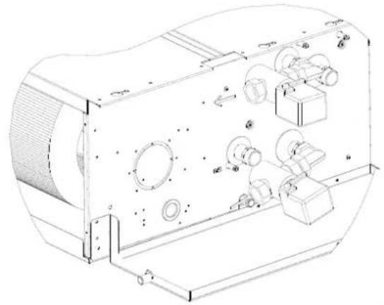
Exploded view
1
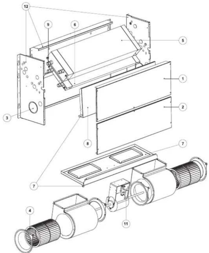
Legenda/Legend/Legende/Legenda/Jelimagyarazat
1
Panne lo di chiusura superiore / Upper closing panel / Panneaux de fermetre supérieure / Untere Verschuiussplatte / Panel de cierre superior / Felsz zopanel
2)
Pannello di chiusura inferiore / Bottom closing panel / Panneaux de fermetre inferieure / Obere Verschlussplatte / Panel de cieme inferior / Also zaropanel
3]
Pretnantia immmise an esti / nake of external air pre - out slot / Raccordement d'arrive d'air estrieur / Runde, vongestane Offing fur Auernluinclasung / Tropeledto introducion are exterior / Flotes wagat kilsievego boyccteseh
4]
Ventilator centrifugi / Centrifugal fans / Ventilators centrifuges / Zentrifugalluter / Ventiladorace centrifugos /Centrifugalis ventilatorek
5
Scambatoridcalorestandd/Standard heat exchanger / Changeurs de chaleur standard / Standard Wermetauscher / Cambiardo color estandar / Standard hocserel
6)
Scambiatore di calore addizionale / Additional heat exchanger / Lchangeur de chaleur additionnelle / Lusatz-warmetauscher / Cambiador de calor adriaional / Jorulekos hoserel
7
Vasca raccolta condensa per installazione a parate (tubo 3/8") / Condensate drip tray for wall mounted installation (pipe 0/3/8") / Cune recolte eau de condensation pour installation murale (tuyau 0/3/8") / Kondenswonne fur Wandinstalation (Rohr 0/3/8") / Depiso rrecogia condensation para instalacion en parate (tubo 3/8") / Kondenzait viz gviijfo tekno falra sereleshez (cs0 3/8")
8
Vasca raccolta condensa per installation a softto (tub 3/8") / Condensate drip tray for ceiling mounted installation (pipe 3/8") / Cuvé récolte eau de condensation pour installation au plafond (tube 3/8") / Kondenswonne für Deckeninstallation (Rahr 3/8") / Deposito recogia condensation para instalación en techo (tub 3/8") / Kondenzit zvi gyjto temo plafona sereleshez (csd 3/8")
91
Installation configurations
7
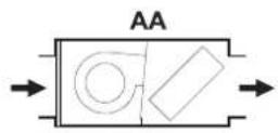
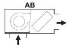
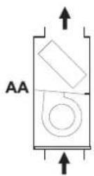
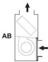
AA Aspiratoire in linea - mandata in linea / AA Intake line - delivery line / AA Aspiration en ligne - couflage en ligne / AA Horizontaler lufreinzug - horizontale laufausblasung / AA Aspiration en linea - salida en linea / AA Szwiat voniban - nyomds vonalan
AB Aspiración a 90^ -mandata in line/ AB 90°-nate-delivery line/ AB Aspiration a 90^ -souflage en linge / AB Ansaugung 90^ -ausblasing in line/ AB Aspiracion e 90^ -salida en line/ AB Szras 90°-ban-mommas vonblan
Example for installation by means of channels
》8
Legenda/Legend/Legende/Legenda/Jelmagyarazat
1) Unita FWN / FWN unit/Unite FWN / Einheit FWN / Unidad FWN / FWN Keszüllbeck
2) Modulo di aspirazione con filto ari (accessory) / Air intake module with air filter (accessory) / Modulo d'aspiration avec filtre air (accessory) / Luftzeugmodul mit Luftfilter (Zubehor) / Modulo de aspiracion con ilto aire (accessorio) / Legoszero modul surovel (tarozek)
3) Glunio antivbrane (accessorio)/Vibration durnper (accessory)/ Joint antivbralone (accessorie)/Schwngungsdampfende Kupplung (Zulohor)/ Junia antivbracion (accessorio)/ Rezgeissllap15 llesfoarab (Lartocik)
Raccordo a 90° di rinnasa ania (accession) / 90° air recycle elbow (accessory) / Raccordà 90° de reprise d'air (accessaire) / 90° Muelle fur Lufuurnwitzung (Zubebr) / Unión de 90° de recupetación aire (accessorio) / A ligtbeamló 90° os calita kozá (tarozék)
Pannl di collegamento canali (accessory) / Panel for the connection by channels (accessory) / Panneau de raccordement par canaux (accessaire) / Verbindungsplate fur Kanalysystem (Zubehor) / Pala de conexion de canales (accessorio) / Cstakozegyseg a lgecatomahzot (tartozé)
6)
7) Grigla di mandata aria (accessory) / Air outlet grille (accessory) / Grillde refoulement d'air (accessaire) / Luftausblaasger (Zubehir / Rejilla de expulsion del aire (accessario) / Alegbefuvo restedyta (tarnozek)
8) Controsofftio /Ceiling-mount /Fauxplafond /Zwischendecke /Falso techo /Almennyeze
》9

Legenda / Legend / Légende / Legende / Leyenda / Jelimagyarazat
1) FWN/FYN unit/Unite FWN/Einheit FWN/Unidad FWN/FYN Keszülikek
2) Modulo di aspirazione con filtrato ari (accessory) / Air Intake module with air filter (accessory) / Module d'aspiration avec filtre air (accessaire) / Luftzeugmodul mit Luftfilter (Zubehor) / Modulo de aspiracion con filtre aire (accessorio) / Legesivo modul suirevol (tarozek)
3) Tuba fiisble di aspienza non colbentao (accessory) / Not inslated flesible ducts for inlet air (accessory) / tyaou flieble non isole de aspiration (accessaire) / Nict isolier Ansaagschauch (zubehor) / tube fi xible de asilacion no aislado (accessory) / A legesivne nem sigeelie ggecsave (Lariz/4k)
4) Cassette di aspirazione con riglia alveolare (accessory) / Air iniet plienum box with double row grille (accessory) / Boite d'aspiration avec grille alveolaire (accessorie) / luneinzugskasten mit Wabengitter (Zubehur) / Gaje de aspiration con regilla alveolar (accessory) / Legissezio cisalakozidobho metsejtraccal (tartozek)
5) Pannne di collegamento a tubi flessi (accessory) / Connection panel by flexible dutes (accessory) / Panneau de raccodement a tubes fi exibles (accessaire) / Verbindungsplatte für Schlauchsystem (Lubehor) / Panel de conexión de tubos flexibles (accessori) / Gattarozegeyseg gégcsevkehz (harzeké)
6) Iubf flesible di mandata (accessory) / Outlet flieble ducs (accessory) / lube flieble de souflage (accessaire) / solierter Lufausblaschauch (Zubehor) / Iubf f xible de enio aiado (accesorio) / Alegbefuoy ggeosive (tarozik)
7) Cassetta mandata con griglia orientable a 2 vie (accessory) / Air outlet plenum box with 2 ways grille (accessory) / Bolte de refoulement avec grille orientable à 2 voies (accessaire) / Luftausblaskasten mit in zwei Richtungen verstellbaren Gitter (Zuehor) / Caja de envio con rella orientable de 2 vias (accessorio) / Uleghevido ketutas, althato riccali (tartozek)
8) Controsoffito /Ceiling-mount /Fauxplafond /Twischenderdeck/Falsstecho /Almennyeret
Horizontal installation slope
10
Filter
11

1)
Standard/ISD6 Modul di spirazione con filto / Air intake modules with filter / Modules d'aspiration dotes de filto / lufteinzugomodule mit filto / Modulos de aspiracion con filto / Legbeszwo modulok szurvel
2)
Il filto a, fissato al modulo di asprazione modi ante vi, sistra e casotto / The air filter, secured to the intake module by means of screws, is pulled out like a drawer / Le filto a air, fato au modulo d'aspiration au moyen de vis, est extrai en maniere de tiroir / Der am Luftansagmodul angeschautle Lufifitter wird wie ein Schublach herausgezogen. / Il filto del aire, suejo a modulo de asprazione medico tornillos, se extrae como cajon / A legbesizó modo haz cavamokal rigzitett légsziru khuizv elativothat
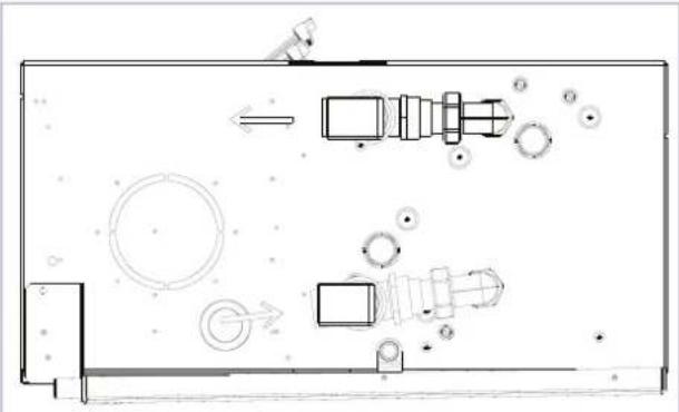
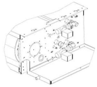
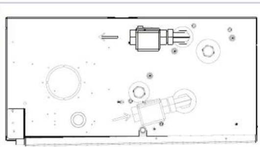
Heat exchanger changing water side connections
》12
STEP2
12 STANDARD MODELS KIT VALVE
| Tab.1 2 way valve kit | ||||||||
| FCU Models Sizes | 2 way valve kit230V on/off singleheat exchanger | DN Kvs | 2 way valve kit 230V on/off single+Additional heatexchangers | DN_single andAdditional heatexchangers | Kvs_single andAdditional heatexchangers | Max working pressure PN(Bar) | ||
| FWD/N 04-05 | ED2MV2B04A6 3 | 4" M 2,8 ED4MV2B04A6 3/4" M 2,8 16 | ||||||
| FWD/N 06-10 | ED2MV2B10A6 1 | M 4,5 ED4MV2B10A6 1" M 4,5 16 | ||||||
| FWD/N | 12-18 | ED2MV2B18A6 | 1" F | 16 | ED4MV2B18A6 | 1" F | 16 | 16 |
| Tab.2 | 3 way valve kit | |||||||||
| FCU Models | Sizes | 3 way valve kit 230V on/off single heat exchanger | DN | Kvs | Kvs BP | 3 way valve kit 230V on/off ingle+Additional heat exchangers | DN_single and Additional heat exchangers | Kvs_single and Additional heat exchangers | Kvs_BP_single and Additional heat exchangers | Max working pressure PN (Bar) |
| FWD/N | 04-05 | ED2MV04A6 | 3/4" M | 2,5 | 1,6 | ED4MV04A6 | 3/4" M | 2,5 | 1,6 | 16 |
| FWD/N | 06-10 | ED2MV10A6 | 1" M | 4,5 | 3,1 | ED4MV10A6 | 1" M | 4,5 | 3,1 | 16 |
| FWD/N | 12-18 (*,++) | ED2MV18A6 | 1" F | 16 | 3,2 | (2x) ED2MV18A6 | 1" F | 16 | 3,2 | 16 |
The 3 way valve kit includes hydronic kit, drain pan and valve body insulating shell
(1) for sizes 12 + 18 , only the valves and the corresponding servomotor are supplied. For these series it is preferable to install units and valves together with the associated servomotors, not at the back of the units, but in a position adjacent to the main hydraulic circuit.
(^*) For sizes 12 + 18 the drain pan is not included in the kit. Always insulate the valve to avoid condensate formed on the valves
| Tab.3 | 2 way Pressure Indipendent 230V kit | |||||
| FCU Models Sizes | Pic-Valve kit 230V on/off single heat exchanger | DN_STD Coil DN | Additional Coil | ΔP_Diff min STD COIL [kPa] / Q_water min [l/hr] * | ΔP_Diff min ADD COIL [kPa] / Q_water min [l/hr] * | |
| FWD/N | 04-05 | FWDNVPIC2V20 | G 1 A | / | 16 | 110 | / |
| FWD/N | 06-10 | FWDNVPIC2V25 | G 1½ A | / | 20 | 340 | / |
| FWD/N | 12-18 | FWDNVPIC2V32 | G 1½ A | / | 25 | 640 | / |
| FCU Models Sizes | Pic-Valve kit 230V on/off single+Additional heat exchanger | DN_STD Coil DN | Additional Coil | ΔP_Diff min STD COIL [kPa] / Q_water min [l/hr] * | ΔP_Diff min ADD COIL [kPa] / Q_water min [l/hr] * | |
| FWD/N | 04-07 | FWDNVPIC2V2015 | G 1 A | G 3/4 A | 16 | 110 | 16 | 65 |
| FWD/N | 08-10 | FWDNVPIC2V2520 | G 1¼ A | G 1 A | 20 | 340 | 16 | 110 |
| FWD/N | 12 | FWDNVPIC2V3220 | G 1½ A | G 1 A | 25 | 640 | 16 | 110 |
| FWD/N | 16-18 | FWDNVPIC2V3225 | G 1½ A | G 1½ A | 25 | 640 | 20 | 340 |
2 way valve kit installation example FWN 8-10 2 way valve kit installation example FWN 16-18
3 way valve kit installation example1) On mode;2) By-Pass mode
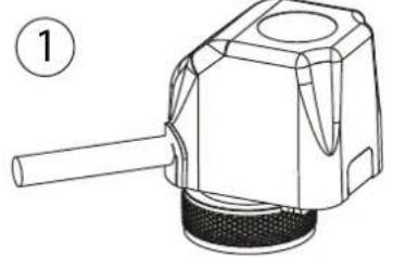
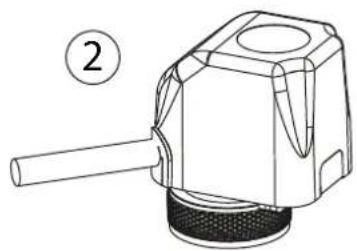
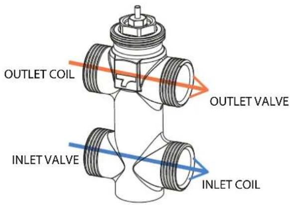
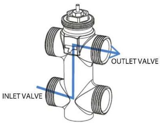
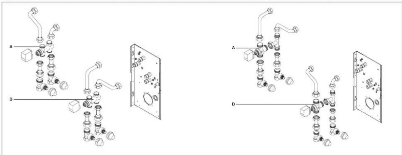
A: For standard heat exchanger B: For additional heat exchanger
13 FWN WIRING DIAGRAMS
Base wiring diagram FWN 04-07
13
Base wiring diagram FWN 08-10
》14
15
FWECSAPA Electrical wires factory mounted:
» Base wiring diagram FWN 04-07 FWECSA Valv. On/Off 230 Vac
》16
17
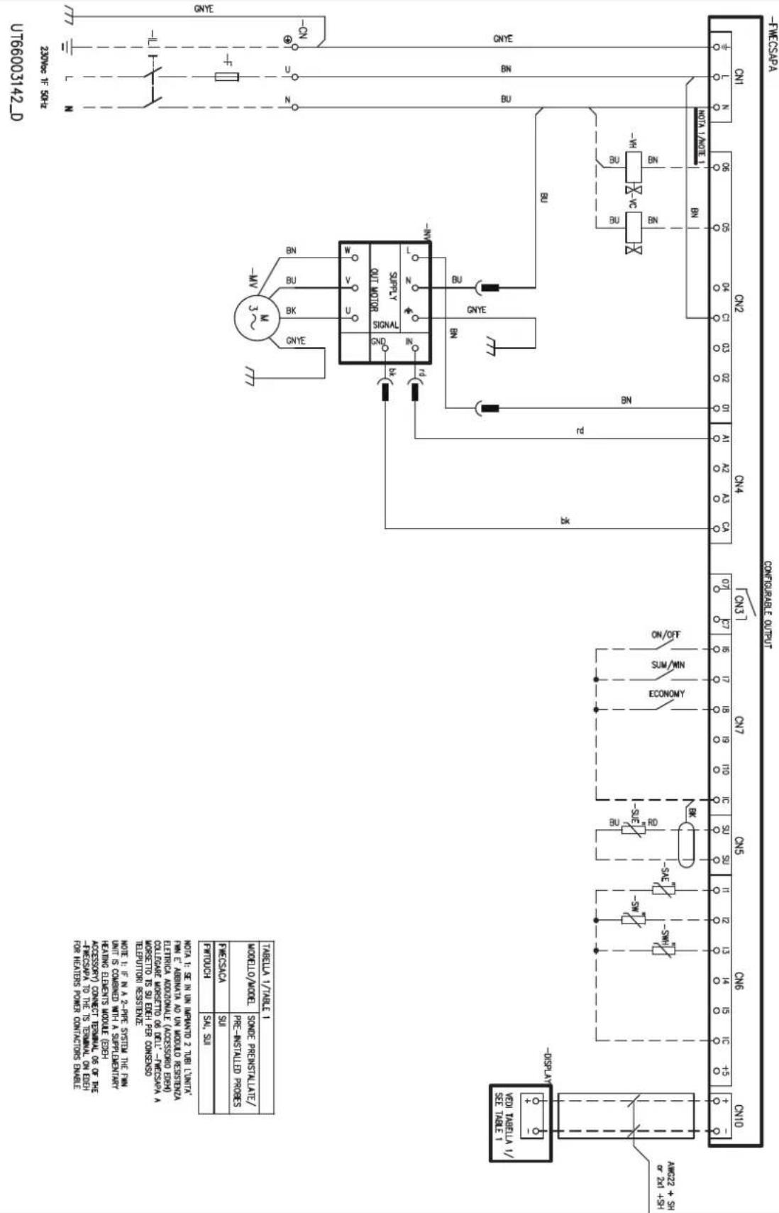
Base wiring diagram FWN 12-18 FWECSA Valv. On/Off 230 Vac
18
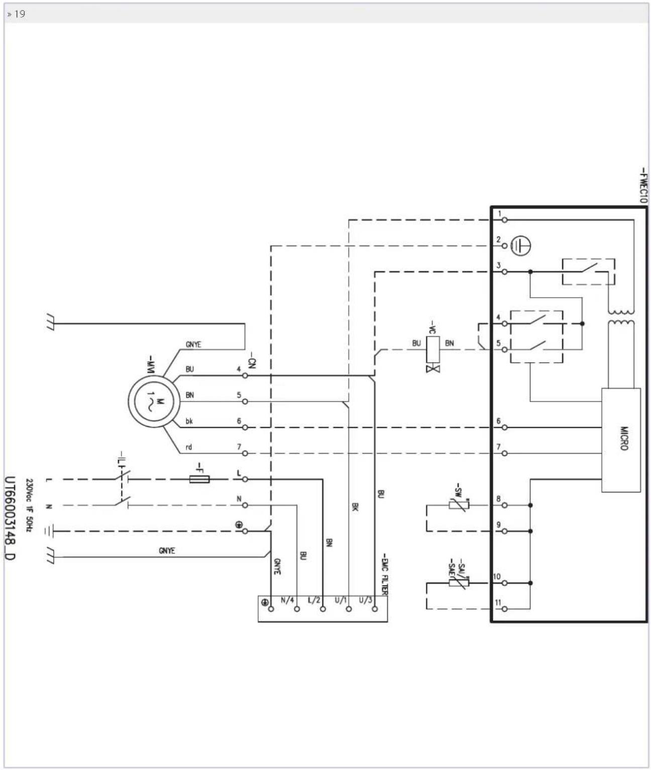
FWEC10 Wiring diagram on FWN 04-07-4 pipes system
》20
FWEC10 Wiring diagram on FWN 08-10-4 pipes system
22
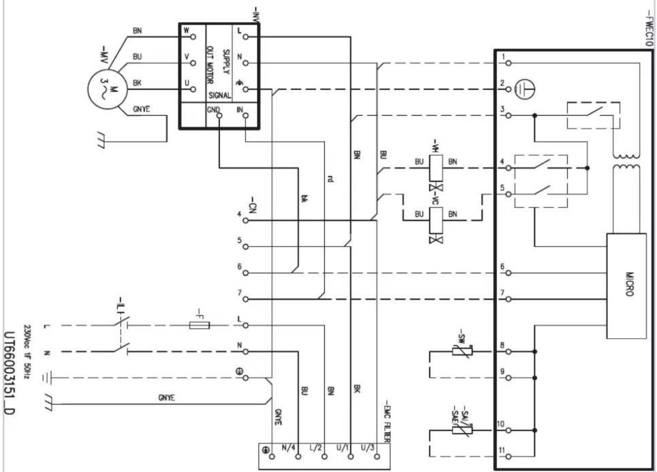
23
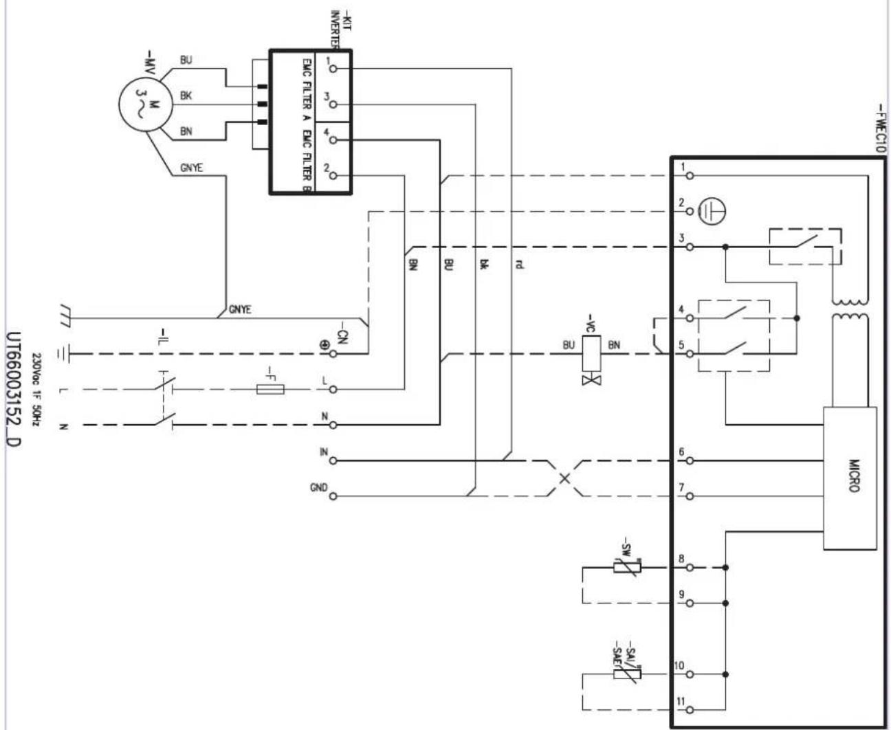
FWEC10 Wiring diagram on FWN 12-18-4 pipes system
24
0-£9£0099
25
FWEC3A Wiring diagram on FWN 08-10 - On/Off valve 230 Vac
26
27
FWECSAPA Wiring diagram FWN 04-07 - On/Off valve 230 Vac
28
29
FWECSAPA Wiring diagram FWN 12-18 - On/Off valve 230 Vac
30
- RICERCA DEI GUASTI
- BEFORE STARTING THE INSTALLATION PROCEDURE
- TRANSLATION BY ORIGINAL INSTRUCTIONS
- SAFETY SYMBOLS
- DESCRIPTION AND INTENDED USE
- INSTALLATION SITE
- Not be overcome the following concentrations of polluting factors in the air environment where the unit is installed:
- WATER QUALITYWARNINGS
- The water used to power the circuit can't overcome the levels indicated below:
- DIMENSIONS AND TECHNICAL DATA
- ACCESSORIES
- INSTALLATION REQUIREMENTS
- Warning for ducted units:
- INSTALLATION
- Some rules to follow:
- WARNING:
- ASSEMBLY OF UNITS
- ELECTRICAL WIRING DIAGRAM LEGEND
- FWECSAPA control electrical wiring diagram legend
- ELECTRICAL CONNECTIONS
- Characteristic of inverter control
- CHECKS BEFORE STARTUP
- EXAMPLE OF INSTALLATION
- USE
- MAINTENANCE
- CLEANING THE AIR FILTER
- CLEANING THE HEAT EXCHANGER
- TROUBLESHOOTING
- Basic Stromanschlüsse abb.61:
- Caracteristicas de regulacion del invorsor
- FIGURES
- Exploded view
- Legenda/Legend/Legende/Legenda/Jelimagyarazat
- Installation configurations
- Example for installation by means of channels
- Legenda/Legend/Legende/Legenda/Jelmagyarazat
- Legenda / Legend / Légende / Legende / Leyenda / Jelimagyarazat
- Horizontal installation slope
- Filter
- 1)
- 2)
- Heat exchanger changing water side connections
- STANDARD MODELS KIT VALVE
- FWN WIRING DIAGRAMS
Brand : DAIKIN
Model : FWN12AATN6V3
Category : Air-conditioner