
FWH08AAT - Air Conditioning DAIKIN - Free user manual and instructions
Find the device manual for free FWH08AAT DAIKIN in PDF.

User questions about FWH08AAT DAIKIN
0 question about this device. Answer the ones you know or ask your own.
Ask a new question about this device
Download the instructions for your Air Conditioning in PDF format for free! Find your manual FWH08AAT - DAIKIN and take your electronic device back in hand. On this page are published all the documents necessary for the use of your device. FWH08AAT by DAIKIN.
USER MANUAL FWH08AAT DAIKIN
natural_image
Interior view of a ceiling-mounted HVAC unit with ventilation grilles and mounting bracket (no text or symbols visible)CE
| EU – Safety declaration of conformityEU – Sicherheit-KonformitätskeräkingUE – Declaration de conformité de sécuritéEU – Conformitätskeräking veiligheid | UE – Declaračtion de conformidad sobre seguridadUE – Dichiarazione di conformità in materia di sicurezzaEE – DAVMI ovuškoporvings yos mye oprekvasUE – Declaračtion de conformidade relativa à segurança | EC – Заплавление о соответствии требованиям по безопасностиEU – Sikerkerheds-overensstemmelseerserkleringEU – Konformitetsdeklaration för sikerket | EU – SANSERSERKLER for sikkerhetEU – Turvallisuiden vastimuseemukaisausvakutusEU – Bezlećnostni prohléseni o shodě | EU – Čigva o sukladnosti za segurnostEU – Biztonsági megfelelevi gyliytkozatUE – Deklaracja zgodnosci iz wymogami bezpieczeństwaUE – Declaratie de conformitate de šiguraná | EU – Varnosna izjiva o skladnostiEU – Ohusse vazvavudektratsionEC – Декларация за съответствие за безопасност | EC – Декларация за съответствие за безопасностES – Drožibas abtilisitas deklarsicjaEU – Vyhlásenie o zhode BezlećnostAB – Güvenlik uygunlak beyan | |||
| Daikin Europe N.V. | |||||||||
| 01 | • deciana under its sole responsibility that the products to which this declaration relates:02 • erdler in aalinege Versanovierung, dass die Produkte, auf die sich diese Erdänung beszen:03 • déclare sous sa seule responsabilise que les produits visas par la onsete dissection:04 • verklaart herbst yo oegen versanovordelijkheid dat de producten revoço daze verklaring betrekking heeft:05 • deciara baou su unico individualidad que os productos a los que hace referencia esta declaración:06 • dichara sollo la prova responsabilista che i producti a cu a rifiella questa dichiarazione:07 • brakova šloka uys robožen kdy, tys ciebning, dr. in i pristovina and onalo obvajljana te impotovina bišlomer:08 • deciara sob sua exclusiva responsabilidade que os productos a que esta declaración se refere: | 09 • consolat svokovitely na por suo operativnosti, что продукуєв, к которой експуска настоящую заявление:10 • erdler som emersavstig, al produkterne, som er omittel al detne erkering:11 • delkanari egenskap av huudansang, all produkterna som berói na densa declaration metel al:12 • erdler an tulsildeng answer for at produtene som er undragt denne erkitantigen:13 • imoltaa yksinnam orale vastuulasi, estiti támán imoltusen tano/tamal lučitec:14 • pronaije se ovu privu odvodnost, ze výrodyk, ve výryn se lobo protabilisi izvanuje:15 • újlenjuje podi slujljivo vislom odgromotinku da su produkod na voje se eva čevna ochosi:16 • teljes feeldlásige tučetabom kjedeln, hogy a termelék, melyeva a rylykozeva voraházak: | 17 • decilanja na wiesna wyjczneza ovedrăsnost, že produkty, theyk by dokracja dotyczy:18 • decilja se proprie răspundenă de productele la care se refera apesia deciantile:19 • 2o odgovortotelj izljena, da so zcelk, na katere se izava nanaša:20 • kritnata ome vastutusel, ta botedi, nella kolela klaslesk deklaratsom vein ibt:21 • dezlnorpa na copa otterworct, ne procedirnite, za koorto ce orenas taxu depravacije:22 • savo diskurne abaskonyde pareška, kad gaminia, kurremi di deklaracija laikoma:23 • ar plini abutilista apiechna, ka zastăbjumi, uz tura iliellas fi develărijaj:24 • hynizaja na vlastru dodporostod, že výrodyk, na krone sa zetanlujo tolo výhlasenie:25 • telk sonvilučki kendane at otnak zazere, bu beyanin igli ocoglu očenimi: | ||||||
| FWH02AAT+6V3***, FWH03AAT+6V3***, FWH04AAT+6V3***, FWH06AAT+6V3***, FWH07AAT+6V3***, FWH08AAT+6V3***, FWH02AAF+6V3***, FWH03AAF+6V3***, FWH04AAF+6V3***, FWH06AAT+6V3***, FWH07AAF+6V3***, FWH08AAF+6V3***, | |||||||||
| *= , , 0, 1, 2, 3, ..., 9, A, B, C, ..., ... Z | |||||||||
| 01 | are in conformity with the following directive(s), or regulation(s), provided that the products are used in accordance with our instructions:02 forderden Rudhinen oder Vorschriften entspechen, vorsageszaki, dass diese geralt unserer instrukczen en venredel versien:03 cont conformes a liabou eletrovi (o) reglement(s) survint(s), a condition que les produits talent utilada confirmament in nos instructions:04 in overeenstrassement zijn mat de valgente richt(en) van de vorenderijen), zo voovansatete dat de producten voren metruld overeenkomstig onze instructies:05 estan en conformate con a(y) signulanti j directed(v), o reglement(s), svemore que sa utildene na acuerdo con nuestras instructiones:06 sono conform allo direttivo o al ojmovimenti seguenti, a patto che i prodotti vengano uszt in conformità alle nostra istruzioni:07 ouquopuowama tu myi (o) olokouyik (i) zdyjaliye, i covonopučupu, umt ny trypovina ognuprotocordina oclupuve ue ti cyjolyek, pi;08 estao en conformidade com a(y) segunte(s) dirilake(s), ou regulamentor(s), desde que os produtos sejam utilizados de acordo com as mossas instructiques: | 09 | отвечит требованием упрокивных niche直达 на норми нормативных документов тим условами инструпальции ценной продукцем в соответствии с навшим як грузниках:10 overhölder poszommetelene (folgende olediyser) eller bestormelde/y, furustat al produtene anvendis i overeenstemmelsa med voraś instruktionen:11 upfetyt fijanje direkti/er (finesfierter), under fortinstattir az industrieme amandsi i enliget med extra instruktioner:12 ei overeenstemnes med folgende direkti/er eller forstiffiler), furostat at produtene brues i herhold si vire instruktioner:13 ovat sourstati i naslodujlimi ememidno mota pladinyi za pladneklada, za lyto výrodyk (jou poudyviny e souadu a nalmi polyyny:14 u skladai as sialoccom direktovymia) il oteodnomia), iz ujevt da sa prozdodi korsta suvladno našim uputama:15 meglelehnek az aliði intervyenik neve egyelo szablyazás/okryn, ha a termelékern e/o/nis szerini horszájk: | 17 | spehnijsa wymogi nastepujyčych cyrekvýtu lub rozupazdžení, sod vanrukmíem že produkty uzkovane sa zgodnie z naszymi instrukcijami:18 sunt in conformate ou umtrakoleve direlvide sau regulamentie, cu corzičija os procusele sa le utilizite in conformate ou inscudlanne nasche:19 y svádua z naslednpi direkti-oy-ami, ali preposzam -ky pod propojem, da sa zitelk, oporobljago v skladu z našim revovioli:20 vastavad (jegmas (argminis, odevilisje je malárate malustrate) klúveve, orgmuisel, el red calustatnava vastuaves mele juhtiste:21 ca o staventstame zas ciepečnicare zperkniknije kri pannamertini, priy ovopne ve postyrnite ce ocoransar a sčuvartestave c našnme instrukcijami:22 zátkila tolau nuodyjas oledrycas abra reglamentos, su svágya, kad gaminal bus aksplicatouvam lankaris muci, instrukčiy:23 stolst šledm direkti-val va regulana, u jevr dle zaštědýjmu fek tovoi sakantoj ar m/uša instrukcijam:24 sv i zvede na nesledjujoučimli smernocoum(arm), alebo orecocsummi za predpodađa, že sa výrodyk použ/vejli v zdohe s našimi povynički:25 talimallamiz doğultunsunca uklamnasi kosytulya agydalski direkti/edtricklifera veya výjnelemilgėvylmeltelkire uygun odlutjmu, beyan adar: | ||||
| Machinery 2006/42/EC**Electromagnetic Compatibility 2014/30/EU*Low Voltage 2014/35/EU | |||||||||
| 01 | following the provisions ofgeranič den Bestimmungen in:02 conformément aux disposizioni da:03 velgens de boonalingen:04 siguiendo las disposizioni de:05 secano le disposizioni di:06 oplupuva tu myi (po) projupučius:07 seguono as disposizioni de:08 a contrastamento con potrimenkennem: | 10 | as amended:02 In der jewals gülliger Fassung,03 telles que modifišis,zsats gewalizigt,05 en su fonte eminertado,06 e successive modifiške,07 omyčy āpovu portomartjed, | 08 conforme emendido,09 a ježetručyšek pečavanim:10 som tillveit,11 med tillég,12 med foretatte endringer,13 sellasina kuin ne ovat mušetulina, | 14 v vlastném zraeli,15 kako e izljenjerio amancanima,16 és mcdotslāsk ranaokazisket | 20 kosos muoculstega,21 c senkita komarennenes,22 I jas tolasnas realizacijes,23 ar grozjumien,24 v posřednom platnom vysan;25 begyšnitodji yevelýke | |||
| 11 | in 31 kladuz ovočbeni;20 vastanir -koliseleva:21 cloganaviliu varyapanta na22 vaozovajants liča ocumento nuodztonama:23 atološti šilo supporte prestihim:24 naslostovnej ustanovemil:25 pi standaričan i učkivnierhe: | ||||||||
| 01 | following the provisions ofgeranič den Bestimmungen in:02 conformément aux disposizioni da:03 velgens de boonalingen:04 siguiendo las disposizioni de:05 secano le disposizioni di:06 oplupuva tu myi (po) projupučius:07 seguono as disposizioni de:08 a contrastamento con potrimenkennem: | 09 | 19 | EN60335-1: 2012 + A11: 2014 + A13: 2017 + A1: 2019 + A14: 2019 + A15: 2021, EN60335-2-40: 2003 + A11: 2004 + A12: 2005 + A1: 2006 + A13: 2012 + A2: 2009, EN 55014-1: 2017 + A11: 2020, EN 55014-2: 2015, EN IEC 61000-3-3: 2013 + A1: 2019, | |||||
| 01 | Note:as set out in «A» and jumped posslieby by «O» according to a Certificate «O» | 06 Note:aome delineato in «A» e gliudato positivamente da «B» al sensi oeri Certifica«O» | 11 Information:som ananges «A» och godiklatis av «D» enligi Certifica«O»som del fenomianer «A» og vurstel positiv an «B» i homod til Sertifikatet «C» | 18 Megjegyzis:a2«A» aikajat. a2«B» igrazolia a megleleket. a2«C» tanisihvany szemt.zyogohne z dokumentasja «A» pozyygena ovinga «P» sviadectwim «O»asa cum se previse in «S» spresal pozitiv de «B» conform Certificatuli«Kur je dočibno v «A» in je prejelo pozitivno ocano 24 Poznámka«B» su skadu a Certifikatom«Ms on castebud dokumentos «A» ja hinnud vaslobedla dokumentos «B», vasilivat Serffikaadile«O» | 21 Šabenexnakaa22 Pastaba23 Piedīmesa‘B’ nočenice na koncenerno on «B» «Cuthanics Serfrekvarka»kaip rurodyta «R» trægjama ruspręsta pagal «B», vazovajerins Sertifikatu«N»na načnódis «A» un pozčiv novrész <B> sakarpjá ar Serifikatu«A»so boio stanovende «A» a kladna posladené «B» podla Odvedcenia«A» de beirlidéj ve Sertifikasna göre «B» teralincen ournu gočky bidrtelégi uzeré. | ||||
| 02 | Hinweis'wie in «A» aufgetunt und von «O» positive beurall gemäl gemäl Zertifikat«Telfelles que définies certa «E» é avduées posvimentment par «B» conformément a Certifica«O» | 07 Zykučnocy° | 12 Merk‘13 Huom‘ | 17 Uwaga:a19 Nota‘19 Nota‘19 Opornba‘20 Márkus‘ | 22 Stato a kucaneno a «A» u queneno poslovitely on «B» «Cuthanics Serfrekvarka»kaip rurodyta «R» trægjama ruspręsta pagal «B», vazovajerins Sertifikatu«A»na načnódis «A» u požedni vovrész <B> sakarpjá ar Serifikatu«A»so boio stanovende «A» a kladna posladené «B» podla Odvedcenia«A»de beirlidéj ve Sertifikasna göre «B» teralincen oornu gočky bidrtelégi uzeré. | ||||
| 03 | Remarque'stellues que définies certa «E» et provasen posvimentment par «B» conformément a Certifica«O» | 08 Notea‘Ank výkoucezet im «A» en poslafte beondred dos <B» overvenmortigt het Certifica«Telfals como se asstaltene en «A» y vavorato posvimentmente de «B» da acuarto com a! Certifica«O» | 13 Huom‘ | 18 Negag’19 Uwaga’a19 Opornba‘20 Márkus‘ | 22 Pustaba’23 Piedīmesa‘B’ nočenice na koncenerno on «B» «Cuthanics Serfrekvarka»kaip rurodyta «R» trægjama ruspręsta pagal «B», vazovajerins Sertifikatu«A»na načnódis «A» u požedni vovrész <B> sakarpjá ar Serifikatu«A»so boio stanovende «A» a kladna posladené«B» podla Odvedcenia«A»de beirlidéj ve Sertifikasna göre «B» teralincen oornu gočky bidrtelégi uzeré. | ||||
| 04 | Bemerk“zoas uštengezet im «A» en poslafte beondred dos <B» overvenmortigt het Certifica«Telfals como se asstaltene en «A» y vavorato posvimentmente de «B» da acuarto com a! Certifica«O» | 09 Pramencaniche‘Ank výkoucezet im «A» e importarenden «O» corraceo ‘Cukapenteri’Soam entrandt «A» og positir vurdatet af <B> i horhovic’15 Napomena‘I Certifica«O» | 14 Poznámka‘Ank výkoucezet im «A» e importarenden «O» | 15 Dalike Europe N.V. on valsuteli bilasman Teklinen asiakijan.16 Spiekredn Daklin N.V. ma opraklenii ke compalačiu socihniki konstrukta.17 Davine Europe N.V. ovo autorizati na stručaču konstrukta konstrukta.18 Davine Europe N.V. ovo autorizati na stručaču konstrukta konstrukta. | 19* Daklin Europe N.V. je probisfičen za seskavo datoleka se tehnito maro.20* Daklin Europe N.V. ovelvatul konstamin artniliči dokumentat.21* Daklin Europe N.V. ovetropučana za cystančna actuna Archa za tenučnučna konstrukcija.22* Daklin Europe N.V. vya goliata sudariyi u technišes konstrukcijos fali.23* Daklin Europe N.V. irautoričlis sæstić tehnsiko dokumentiju.24* Spolezhner Daklin Europe N.V. oventvend výront prostchnickoj konstrukcije.25* Daklin Europe N.V. Teknik Yap Dosyasni defemeye yetiklid. | ||||
| 01** Daklin Europe N.V. is authorised to complete the Technical Construction File.02** Daklin Europe N.V. has the Benefchtigung des Technische Konstruktionales zusammenzustellen.03** Daklin Europe N.V. est autorizzato a completar le Dossier de Construction Technique.04** Daklin Europe N.V. is berovere om net Technistron Constructedossiers samen le steilen.05** Daklin Europe N.V. est autorizzato a configare al Archino de Construcción Tecnica.06** Daklin Europe N.V. è autorizzata a religiene il Filo Tecnico di Constructione. | 07** A Daklin Europe N.V. āvra odravnočkomnyjky na ovovlja.08** A Daklin Europe N.V. estis autorizzata a configare al Complare a documentate tecnica de fabrico.09** Komasnik Daklin Europe N.V. uvohovnečena ecozombe Kovomine nevskovet konstrukcijani.10** Daklin Europe N.V. er autorizesi at udatebe de tekniska konstruktionalsdata.11** Daklin Europe N.V. ár bereynidgáte aci sammenstalska den tekniska konstruktionären.12** Daklin Europe N.V. har titolatda fi k komplemo den Techniske konstrukcijani. | 07** H Daklin Europe N.V. āvra odravnočkomnyjky na ovovlja.08** A Daklin Europe N.V. estis autorizzada a configare al Complare a documentate tecnica de fabrico.09** Komasnik Daklin Europe N.V. uvohovnečena ecozombe Kovomine nevskoveti konstrukcijani.10** Daklin Europe N.V. er autorizesi at udatebe de tekniska konstruktionalsdata.11** Daklin Europe N.V. ár bereynidgáte aci sammenstalska den tekniska konstruktionären.12** Daklin Europe N.V. har titolatda fi k komplemo den Techniske konstrukcijani. | 13** Daklin Europe N.V. on valsuteli bilasman Teklinen asiakijan.14** Spiekredn Daklin Europe N.V. ma opraklenii ke compalačiu socihniki konstrukta.15** Daklin Europe N.V. ovo autorizati na stručaču konstrukta konstrukta.16** Daklin Europe N.V. ovo autorizati na stručaču konstrukta konstrukta. | 19** Daklin Europe N.V. je probisfičen za seskavo datoleka se tehnito maro.20** Daklin Europe N.V. ovelvatul konstamin artniliči constructat.21** Daklin Europe N.V. ovetropučana za cystančna actuna Archa za tenučnučna konstrukcija.22** Daklin Europe N.V. vya goliata sudariyi u technišes konstrukcijos fali.23** Daklin Europe N.V. irautoričlis sæstić tehnsiko dokumentiju.24** Spolezhner Daklin Europe N.V. oventvend výront prostchnickoj konstrukcije.25** Daklin Europe N.V. Teknik Yap Dosyasni defemeye yetiklid. | |||||
| EU-Ecodesign declaration of conformityEU-Okodesign-KonformitätserklierungUE-Déclaration de conformité en matière d'écoconceptionEU-Conformiteitsverklaring ecologisch ontwerpUE-Déclaration de conformidade sobre disetio ecológico | UE-Dichiarazione di conformità alla progettazione oaccomplitibileEE-Ärjkiung muyaparvung yra tevo onkolykó cyebankýUE-Déclaration de conformidade relativa à concieção ecológicaEC-Zavainene o coortretstria trebozniemn Direktivna po ekoliplozazinn (Ecodesign)EU-Oversamstemmiseserklarting miljeveniligi design | EU-Konformitatelekolortion für EcodesignEU-Samsvarserklaring for okodesignEU-Ekosuumittellun valmistusmenmukaisuusvakuutusEU-Prohlášeni o shodé ekologické konstrukceEU-Ijava o sukladnosti za za ekolokli dizajn | EU-Ökodizajn megfelelőskégi nyylatkazatUE-Dektaracja zgodnosz i wymogami dotyczaymi ekoprojektuUE-Declaratie de conformitate EcodesignEU-Ijava o skladnosti z zahtevami za okoljako primero zasnovoEU-Ökodisaini vastavusdeklaratssoon | EC-Декарация за съответствие с екодизайнES-Ekodizaino atitiklides deklaracijaES-Ekodizaina atbilsfibas deklaracijaEU-Vyhlasenie o zhode EcodesignAB-Eko-tasamm uygumluk beyani |
| Daikin Europe N.V. | ||||
| 01 ⬆e cedares under its sole responsibility that the products to which this declaration relates:02 ⬇e erklatt auf sisi no alalige Verantwortung, dass da Produkte, auf die sich diese Erklaring bazint:03 ⬇e cedares sous sa seu responsabilità que les produits vida par la presente déclaration:04 ⬇e verklam [verzi] op operi exclusive veratnomooijheid dat de producten anerop ozeo verlasing betraking heeft:05 ⬇e cedares nayo ou unice responsabilidades que os productos a o que noce referenza la déclaration:06 ⬇e cedares solta la puera responsabilità che i prodotti cui questa dichiarazione el flance:07 ⬇e Zyklaves ac rotovastemery [my cuklon' on te mafoivita otra smola ovoguciana y marpoole Zyklwam:08 ⬇e cedares subc sua exclusive responsabilitàde que os productos a que esta declaraçao se refano: | 09 ⬆zavainant, konsontitelys na pod ovoa tveletsehnoty, itto kaderina, k totromyi stronostt hactoiauje zastrežnne:10 ⬆orklaret som umansarving, ar azdysnai, som ar omifalt al domne erklaring:11 ⬆dolarar orpanak av huvudanswirg att de produktar som berits av derine deklaraton glalter:12 ⬆orklaret of lulsterlig armare for all produzione som tenores av derine devlarasjenen, inrebener at:13 lipazita normanaan omala vastuulan, etla tlān jim intoliukten radoktatal bitzitec:14 ⬆prohlade na smoa svihradn odbovodnost, ze produtky, tarych se prohlafen! Nyld:15 izravljave podi sitajivte vistendu odgovomodci do su prostend na kose ne ova izrava cónel:16 ⬆tejas foilečesląga tudataban vijeriom, hogy a termelak, meylekre o nylatkozat voratnatic: | 17 ⬆declarize na wksna wynczną odówredzianost, ze uzprzazenia, kołych na deklaracja docyocy:18 ⬆dociară za portnia stapurarea ca produvia la cana se tofară acesta ecdarajna:19 ⬆e odgacnomotja tbjarija, da se naprave, na katere se izrava ranaile:20 emlinata atra taliwi valustased, et kalesova declarazionii alfa haulaud tolaste:21 epcaspousa na copa otratoporteciu ve proponeira, sta kanta ce otraca taxi geuparațiu:22 ⬆dinertne savo ataskomybka fial deklarajna, kad producta, su kurals di deklaracija surijsi:23 ap pinlu atitibiou apicaria, va turpak minilla zlododami, uz kurlam attacas di deklarajna:24 ⬆vyhlasuje na vlasnu zodowodnost, ze vytzykty na koris sa ozvahuje toto vyhlásene:25 zamanen kendi sorunitaluju alinda bu bidirnin ilgili oduğlu ünnier beyan eder: | 17 ⬆declarize na wksna wynczną odówredzianost, ze uzprzazenia, kołych na deklaracja docyocy:18 ⬆dociară za portnia stapurarea ca produvia la cana se tofară acesta ecdarajna:19 ⬆e odgacnomotja tbjarija, da se naprave. na katere se izrava ranaile:20 emlinata atra taliwi valustased, et kalesova declarazionii alfa haulaud tolaste:21 epcaspousa na copa otratoporteciu ve proponeira, sta kanta ce otraca taxi geuparațiu:22 ⬆dinertne savo ataskomybka fial deklalajna, kad producta, su kurals di deklaracija surijsi:23 ap pinlu atitibiou apicaria, va turpak minilla zlododami, uz kurlam attacas di deklarajna:24 ⬆vyhlasuje na vlasnu zodowodnost, ze vytzykty na koris sa ozvahuje toto vyhlásene:25 zamanem kendi sorunitaluju alinda bu bidirnin ilgili oduğlu ünnier beyan eder: | 17 ⬆declarize na wksna wynczną odówredzianost, ze uzprzazenia, kołych na deklaracja docyocy:18 ⬆dociară za portnia stapurarea ca produvia la cana se tofară acesta ecdharajna:19 ⬆e odgacnomotja tbjarija, da se naprave, na katere se izrava ranaile:20 emlinata atra taliwi valustased, et kalesova declarazionii alfa haulaud tolaste:21 epcaspousa na copa otratoporteciu ve proponeira, sta kanta ce otraca tax i geuparațiu:22 ⬆dinertne savo ataskomybka fial deklalajna, kad producta, su kurals di deklaracija surijsi:23 ap pinlu atitibiou apicaria, va turpak minilla zlododami, uz kurlam attacas di deklarajna:24 ⬆vyhlasuje na vlasnu zodowodnost. Ze vytzykty na koris sa ozvahuje toto vyhlásene:25 zamanen kendi sorunitaluju alinda bu bidirnin ilgili oduğlu ünnier beyan eder: |
| FWH02AAT*6V3***, FWH03AAT*6V3***, FWH04AAT*6V3***, FWH06AAT*6V3***, FWH07AAT*6V3***, FWH08AAT*6V3***, FWH02AAF*6V3***,FWH07AAF*6V3***, FWH08AAF*6V3***, | ||||
| *= , 0, 1, 2, 3, ..., 9, A, B, C, ..., Z | ||||
| 01 are in conformity with the following directive(s) or regulation(s), as amended:folgendem Röchlinen oder 'Vorschrän' in der jewels gälligen Fassung entsprechen:02 satislant da los au dos directive(s), savanlens(s), et la su aux reglementations(s), desi plas y amendées:03 inoverensamming bez mit de volgende rothlin(s) of versomition(s), ostrigewaglpt:04 están en conformidade con lasj signaties(s) direktiva(s) o reglement(s), en as forma emmendada:05 sono conformi con le seguent directive o reglementi, a successive modifiche:06 čeva cujučavu je tuotn's adkoultujic (očivýs(c) kon kovowučučuč), omu's tractornid'inkov( );07 erclavo em conformidade com a(s) segunit(s) direktiva(s) ou regulamenti(s), conforme emndatic: | 09 stvenent trađobavem na komnuktyk na veje pravite inna komnuktyknek documents e deklarajnać reduzni:10 overhider besetemnatejna i folgende diselivir/er alle bestamnatejna, som briječ:11 apylityr fjanje idevrije eller regenets, med bilag:12 i coveredismandrode merl folgende diselivir/er alter tonnilvirj, med borate endringer:13 noudalizati suračava diselivirja tai mandyká saitašina na koi ne ovat mutatlina:14 sou ve shodé a nasedujčini smirenicomi a otopisy v platrem ztržni:15 u sladu sa sjiedečnim/jm diresvomianja ii proziom/ma, tako je zmienjerno amandmaniras:16 neglelnek az alabli irányaljek/nek vagy egyéb szabalýozde(ox)nek a sielegzštěsnek megfeleiden: | 17 sveniela wymocji nastepalujych dyreków lao rozporzadeži, z pólnejszom i zmlanami:18 sunt in conformitate cu urmlatorie drevice sau regulamenta, su amandamerone respective:19 v skladu z nasedijro direkivbyc armi ai predomis(n), ki je bdo spramencje v:20 vaslasen (jagminole direkivibide nučineve val tenele nučekud ničineve):21 otracaprt na clograta propionravvi i portanevi(n), z tomničke ovočnava:22 atinka tolika nurodyas diselivitas arba regementus ir j rodaklja:23 abtit adáter diselivár val regulaimi ar prozjumiem:24 su v ztoce o nasledonvomijm (smerincuavi) a predplesom/nj, doplerné:25 degijstřídig saklyve apojdoid diselkaftdnaktifera vegya vornitvelgjavymalteliklere ugun oduğunu beyan eder: | ||
| Ecodesign: Directive 2009/125/ECCommission regulations:Airconditioning (EU) 2016/2281 | ||||
| 01 and comply with the following standard(s) or other normative document(s):02 und dum in folgenden Standard(s) odor anteran Norman entproditentiapuchen:03 sont en conformite avec a ou les normesi( standard) ou d'autre(s) normatt(s):04 en woczen aan de volgende normesi (an) of anore(s) normati(ve) document(s) zijn:05 y compten con lasj signaties(s) normasi (u) otro(s) document(s) normati();06 a risplata le norme (o document) normateri portati di seguito:07 es civa dujupuo je tuoto adkoultujic (poločno(s) i troto adkoultujic) konovomtički (ú) gympaq(s):08 e cumprená (ú), seguitates normasi(s) ou otrzo documents normativios aplicarise: | 09 otveent trađobavem na komnuktyk na veje pravite inna komnuktyknek documents:10 og overhider folgende standardje/er alle andre normative documentar:11 apylityr fjanje standardje/er alle andre normerende dokument:12 og sansvarer med folgende standardje/er andreinaret normvende documentar:13 a noudalizati seuračava standarden za malden normalliskn asalajpon vastruklusa:14 sou ve shodé a nasedijčini normami nevo jyfini normatmiti documentu:15 u skladu sa sjiedečnim/jm diresvomianja ii drugim normatimiti document(s);16 és megfeleken az alabli szabalýan(ox)nek vagy egyéb iranyaki documentumiplynak: | 17 ispehnia wymogi nasedoujych nom oraz innych dokumentov normalizajnyjch:18 si se conformatea urmlatorial standarda sa saltor documento normatve:19 u strazayo nasedijrn standardom si drugim zavezučjom documentov:20 tocate vastad jagminale (jagminale) standardle (standardite) valmiule normodumendle (normodumentele):21 a csočenčenčen a chedniki stracijpi (vt) votu gyjny opramiselej doymetvi(j):22 fälltnia toxentius standardus arba allus norminus documentas:23 un abtit adáter standard van citem normativaljem documentom:24 a su v ztoce o nasledonvomijm (normouvatu) aliso finvi(n), (normalinv) (dokumentom)();25 ve apojdaki standardansandariara veya diger normali/ begeyebelgetiene uojuguru beyan eder: | ||
| EN 1397EN 16583, | ||||
| 01 (*) Official approved confirmation(s) can be found in the product catalogues(s).02 (*) Office genahmige kombinationen sind my Prodkultasios(s) aufginalise:03 (*) a lo os combinations(s) apcorband(s) offidulament 'furan' dans lasj catalogues(s) de prodats:04 (*) Official googoodvere combinationes (zin tirang te vinder in de productcatalogues).05 (*) agi combining(s) officinalmente aprobado(s) puede o porden encontanze en os catalogos o catalogo de productos.06 (*) Le combinazione individualmente approvas sono sistrate nei catazogli dei prodotti:07 (*) OVO cujučavu upricjektj (mu) gyrus(s) utromy (kyper muskýtovni) etro konkůvůvčovni, cetakovůvču, pečitovru.08 (*) As combinativas aprovadas oficiais constam dos cataloga dos produtos: | 09 (*) Obschavnics sociropriebe necevskmi uvočn kehta in katalatik ucojeluk.10 (*) Officeli podkierde kombinationjey van neer i studiktalakelik katalogeme.11 (*) Officeli godklanda kombinationer latris i studiktalakalogema.12 (*) Onerlig prodjekte kombinationer (zár oppiti i produktalagen(s)).13 (*) Viralisseti hválalystyj syndistleriy on limcintila tabetueleksisa.14 (*) Ofcalne schvalene kombace je možne naležt katalogu produktii.15 (*) Sztuhano odonana(a) kombinacja(ay) mogu se nadli u sljedečnimjim kataloguizima) proizvoda:16 (*) A valatabson ľvihalystyjt ožestaalitássij(ak) a termiktalakeligak(ok) kan talihatik. | 17 (*) Oficainie zakwidzone zakwidaja kazniogi produktów.18 (*) Combinielle varbanite olceia cf piela in catalogele de produse.19 (*) Urdimo celodrome kombiničnica so distasona vi katarogh tiskiken.20 (*) Ameltikat naeks kalendučkomonistonic(n) levate kotorkaznojdyje st.21 (*) Ospicarnavu opojcepves kombiničniki norat za nečeknapt a notogiyomata katalocu.22 (*) Oficaiai aktivirta kombinacia (-es) gaile rasi produto katacogene (-use).23 (*) Reštalja aspitviradas kombiničnici noraditas izstakajnu katalogus.24 (*) Oficaine schvedan(s) kombiničniki najdiate v vazagu(ox) vihidkov.25 (*) Rezni onayi kombinasyonar iutu katacijgorna radu balunabit. | ||
DAIKIN
| EU – RoHS declaration of conformityEU – RoHS-KonformilitäserklarungUE – Declaration de conformité RoHSEU – Conformilitäserklarung RoHS | UE – Declaración de conformidad RoHSUE – Dichtarazione di conformità RoHSEE – Délyuon grupiórópuwics yto ton περιορού της χρήσης οφομένων ετικήδυνων ουτσαν (RoHS) | UE – Declaração de conformidade relativa à restrição de utilização de determinadas substâncias perigosasEC – Заявление о соответствии требованиями Директивы RoHS | EU – RoHS-overensstemmelseerklaringEU – Konformilitäseklaration für RoHSE – Samvarserklarning for RoHSEU – RoHS-vaatimustenmukalsusvakuutus | EU – Prohlášení o shodé RoHSEU – Izjava o sukladnosti za ograničenje opasnih tvari (RoHS)EU – RoHS megfelelósígi nyitalkozatUE – Deklaracja zgodnosci z dyrektywný RoHS | UE – Declarajte de conformitate RoHSEU – Izjava o skladnosti z direktivo RoHSEU – RoHS vastavusdeklaratsionEC – Декларация за съответствие с дрективата за ограничаване на опасните вещества | ES – PMNA attilkities deklaracijaES – RoHS ablisítibas deklaracijaEU – Vyhlásenie o zhode RoHSAB – RoHS uyguntlak beyani |
| Daikin Europe.N.V. | ||||||
| 01 ⚫ i● i● i● i● i● i● i● i● i● i● i● i● i● i● i● i● i● i● i● i● i● i● i● i● i● i● i● i● i● i● i● i● i● i● i● i● i● i● i● i● i● i● i● i● i● i● i● i● i● i● i— | ||||||
| 02 ⚫2 ⚫2 ⚫2 ⚫2 ⚫2 ⚫2 ⚫2 ⚫2 ⚫2 ⚫2 ⚫2 ⚫2 ⚫2 ⚫2 ⚫2 ⚫2 ⚫2 ⚫2 ⚫2 ⚫2 ⚫2 ⚫2 ⚫2 ⚫2 ⚫2 ⚪2 ⚫2 ⚫2 ⚫2 ⚫2 ⚫2 ⚫2 ⚫2 ⚫2 ⚫2 ⚫2 ⚫2 ⚫2 ⚫2 ⚫2 ⚫2 ⚫2 ⚫2 ⚫2 ⚫2 ⚫2 ⚫2 ⚫2 ⚫2 ⚫2 ⚩2 ⚫2 ⚫2 ⚫2 ⚫2 ⚫2 ⚫2 ⚫2 ⚫2 ⚫2 ⚫2 ⚫2 ⚫2 ⚫2 ⚫2 ⚫2 ⚫2 ⚫2 ⚫2 ⚫2 ⚫2 ⚫2 ⚫2 ⚫2 ⚫2 ⚯2 ⚫2 ⚫2 ⚫2 ⚫2 ⚫2 ⚫2 ⚫2 ⚫2 ⚫2 ⚫2 ⚫2 ⚫2 ⚫2 ⚫2 ⚫2 ⚫2 ⚫2 ⚫2 ⚫2 ⚫2 ⚫2 ⚫2 ⚫2 ⚫2 ⚦2 ⚫2 ⚫2 ⚫2 ⚫2 ⚫2 ⚫2 ⚫2 ⚫2 ⚫2 ⚫2 ⚫2 ⚫2 ⚫2 ⚫2 ⚫2 ⚫2 ⚫2 ⚫2 ⚫2 ⚫2 ⚫2 ⚫2 ⚫2 ⚫2 ⚨2 ⚫2 ⚫2 ⚫2 ⚫2 ⚫2 ⚫2 ⚫2 ⚫2 ⚫2 ⚫2 ⚫2 ⚫2 ⚫2 ⚫2 ⚫2 ⚫2 ⚫2 ⚫2 ⚫2 ⚫2 ⚫2 ⚫2 ⚫2 ⚫2 ⚡2 ⚫2 ⚫2 ⚫2 ⚫2 ⚫2 ⚫2 ⚫2 ⚫2 ⚫2 ⚫2 ⚫2 ⚫2 ⚫2 ⚫2 ⚫2 ⚫2 ⚫2 ⚫2 ⚫2 ⚫2 ⚫2 ⚫2 ⚫2 ⚫2 ⚗2 ⚫2 ⚫2 ⚫2 ⚫2 ⚫2 ⚫2 ⚫2 ⚫2 ⚫2 ⚫2 ⚫2 ⚫2 ⚫2 ⚫2 ⚫2 ⚫2 ⚫2 ⚫2 ⚫2 ⚫2 ⚫2 ⚫2 ⚫2 ⚫2 ⚭2 ⚫2 ⚫2 ⚫2 ⚫2 ⚫2 ⚫2 ⚫2 ⚫2 ⚫2 ⚫2 ⚫2 ⚫2 ⚫2 ⚫2 ⚫2 ⚫2 ⚫2 ⚫2 ⚫2 ⚫2 ⚫2 ⚫2 ⚫2 ⚫2 ⚬2 ⚫2 ⚫2 ⚫2 ⚫2 ⚫2 ⚫2 ⚫2 ⚫2 ⚫2 ⚫2 ⚫2 ⚫2 ⚫2 ⚫2 ⚫2 ⚫2 ⚫2 ⚫2 ⚫2 ⚫2 ⚫2 ⚫2 ⚫2 ⚫2 ⚠2 ⚫2 ⚫2 ⚫2 ⚫2 ⚫2 ⚫2 ⚫2 ⚫2 ⚫2 ⚫2 ⚫2 ⚫2 ⚫2 ⚫2 ⚫2 ⚫2 ⚫2 ⚫2 ⚫2 ⚫2 ⚫2 ⚫2 ⚫2 ⚫2 ⚢2 ⚫2 ⚫2 ⚫2 ⚫2 ⚫2 ⚫2 ⚫2 ⚫2 ⚫2 ⚫2 ⚫2 ⚫2 ⚫2 ⚫2 ⚫2 ⚫2 ⚫2 ⚫2 ⚫2 ⚫2 ⚫2 ⚫2 ⚫2 ⚫2 ⚣2 ⚫2 ⚫2 ⚫2 ⚫2 ⚫2 ⚫2 ⚫2 ⚫2 ⚫2 ⚫2 ⚫2 ⚫2 ⚫2 ⚫2 ⚫2 ⚫2 ⚫2 ⚫2 ⚫2 ⚫2 ⚫2 ⚫2 ⚫2 ⚫2 ⚥2 ⚫2 ⚫2 ⚫2 ⚫2 ⚫2 ⚫2 ⚫2 ⚫2 ⚫2 ⚫2 ⚫2 ⚫2 ⚫2 ⚫2 ⚫2 ⚫2 ⚫2 ⚫2 ⚫2 ⚫2 ⚫2 ⚫2 ⚫2 ⚫2 ⚕2 ⚫2 ⚫2 ⚫2 ⚫2 ⚫2 ⚫2 ⚫2 ⚫2 ⚫2 ⚫2 ⚫2 ⚫2 ⚫2 ⚫2 ⚫2 ⚫2 ⚫2 ⚫2 ⚫2 ⚫2 ⚫2 ⚫2 ⚫2 ⚫2 ⚮2 ⚫2 ⚫2 ⚫2 ⚫2 ⚫2 ⚫2 ⚫2 ⚫2 ⚫2 ⚫2 ⚫2 ⚫2 ⚫2 ⚫2 ⚫2 ⚫2 ⚫2 ⚫2 ⚫2 ⚫2 ⚫2 ⚫2 ⚫2 ⚫2 ⚧2 ⚫2 ⚫2 ⚫2 ⚫2 ⚫2 ⚫2 ⚫2 ⚫2 ⚫2 ⚫2 ⚫2 ⚫2 ⚫2 ⚫2 ⚫2 ⚫2 ⚫2 ⚫2 ⚫2 ⚫2 ⚫2 ⚫2 ⚫2 ⚫2 ⚱2 ⚫2 ⚫2 ⚫2 ⚫2 ⚫2 ⚫2 ⚫2 ⚫2 ⚫2 ⚫2 ⚫2 ⚫2 ⚫2 ⚫2 ⚫2 ⚫2 ⚫2 ⚫2 ⚫2 ⚫2 ⚫2 ⚫2 ⚫2 ⚫2 ⚸2 ⚫2 ⚫2 ⚫2 ⚫2 ⚫2 ⚫2 ⚫2 ⚫2 ⚫2 ⚫2 ⚫2 ⚫2 ⚫2 ⚫2 ⚫2 ⚫2 ⚫2 ⚫2 ⚫2 ⚫2 ⚫2 ⚫2 ⚫2 ⚫2 ⚘2 ⚫2 ⚫2 ⚫2 ⚫2 ⚫2 ⚫2 ⚫2 ⚫2 ⚫2 ⚫2 ⚫2 ⚫2 ⚫2 ⚫2 ⚫2 ⚫2 ⚫2 ⚫2 ⚫2 ⚫2 ⚫2 ⚫2 ⚫2 ⚫2 ⚔2 ⚫2 ⚫2 ⚫2 ⚫2 ⚫2 ⚫2 ⚫2 ⚫2 ⚫2 ⚫2 ⚫2 ⚫2 ⚫2 ⚫2 ⚫2 ⚫2 ⚫2 ⚫2 ⚫2 ⚫2 ⚫2 ⚫2 ⚫2 ⚫2 ⚄2 ⚫2 ⚫2 ⚫2 ⚫2 ⚫2 ⚫2 ⚫2 ⚫2 ⚫2 ⚫2 ⚫2 ⚫2 ⚫2 ⚫2 ⚫2 ⚫2 ⚫2 ⚫2 ⚫2 ⚫2 ⚫2 ⚫2 ⚫2 ⚫2 ⚻2 ⚫2 ⚫2 ⚫2 ⚫2 ⚫2 ⚫2 ⚫2 ⚫2 ⚫2 ⚫2 ⚫2 ⚫2 ⚫2 ⚫2 ⚫2 ⚫2 ⚫2 ⚫2 ⚫2 ⚫2 ⚫2 ⚫2 ⚯2 ⚫2 ⚯2 ⚯2 ⚯2 ⚯2 ⚯2 ⚯2 ⚯2 ⚯2 ⚯2 ⚯2 ⚯2 ⚯2 ⚯2 ⚯2 ⚯2 ⚯2 ⚯2 ⚯2 ⚯2 ⚯2 ⚯2 ⚯2 ⚯2 ⚯2 ⚯2 ⚮2 ⚯2 ⚯2 ⚯2 ⚯2 ⚯2 ⚯2 ⚯2 ⚯2 ⚯2 ⚯2 ⚯2 ⚯2 ⚯2 ⚯2 ⚯2 ⚯2 ⚯2 ⚯2 ⚯2 ⚯2 ⚯2 ⚯2 ⚯2 ⚯2 ⚪2 ⚯2 ⚯2 ⚯2 ⚯2 ⚯2 ⚯2 ⚯2 ⚯2 ⚯2 ⚯2 ⚯2 ⚯2 ⚯2 ⚯2 ⚯2 ⚯2 ⚯2 ⚯2 ⚯2 ⚯2 ⚯2 ⚯2 ⚯2 ⚯2 ⚩2 ⚯2 ⚯2 ⚯2 ⚯2 ⚯2 ⚯2 ⚯2 ⚯2 ⚯2 ⚯2 ⚯2 ⚯2 ⚯2 ⚯2 ⚯2 ⚯2 ⚯2 ⚯2 ⚯2 ⚯2 ⚯2 ⚯2 ⚯2 ⚯2 ⚠2 ⚯2 ⚯2 ⚯2 ⚯2 ⚯2 ⚯2 ⚯2 ⚯2 ⚯2 ⚯2 ⚯2 ⚯2 ⚯2 ⚯2 ⚯2 ⚯2 ⚯2 ⚯2 ⚯2 ⚯2 ⚯2 ⚯2 ⚯2 ⚯2 ⚢2 ⚯2 ⚯2 ⚯2 ⚯2 ⚯2 ⚯2 ⚯2 ⚯2 ⚯2 ⚯2 ⚯2 ⚯2 ⚯2 ⚯2 ⚯2 ⚯2 ⚯2 ⚯2 ⚯2 ⚯2 ⚯2 ⚯2 ⚯2 ⚯2 ⚅2 ⚯2 ⚯2 ⚯2 ⚯2 ⚯2 ⚯2 ⚯2 ⚯2 ⚯2 ⚯2 ⚯2 ⚯2 ⚯2 ⚯2 ⚯2 ⚯2 ⚯2 ⚯2 ⚯2 ⚯2 ⚯2 ⚯2 ⚯2 ⚯2 ⚉2 ⚯2 ⚯2 ⚯2 ⚯2 ⚯2 ⚯2 ⚯2 ⚯2 ⚯2 ⚯2 ⚯2 ⚯2 ⚯2 ⚯2 ⚯2 ⚯2 ⚯2 ⚯2 ⚯2 ⚯2 ⚯2 ⚯2 ⚯2 ⚯2 ⚋2 ⚯2 ⚯2 ⚯2 ⚯2 ⚯2 ⚯2 ⚯2 ⚯2 ⚯2 ⚯2 ⚯2 ⚯2 ⚯2 ⚯2 ⚯2 ⚯2 ⚯2 ⚯2 ⚯2 ⚯2 ⚯2 ⚯2 ⚯2 ⚯2 ⚱2 ⚯2 ⚯2 ⚯2 ⚯2 ⚯2 ⚯2 ⚯2 ⚯2 ⚯2 ⚯2 ⚯2 ⚯2 ⚯2 ⚯2 ⚯2 ⚯2 ⚯2 ⚯2 ⚯2 ⚯2 ⚯2 ⚯2 ⚯2 ⚯2 ⚰2 ⚯2 ⚯2 ⚯2 ⚯2 ⚯2 ⚯2 ⚯2 ⚯2 ⚯2 ⚯2 ⚯2 ⚯2 ⚯2 ⚯2 ⚯2 ⚯2 ⚯2 ⚯2 ⚯2 ⚯2 ⚯2 ⚯2 ⚯2 ⚯2 ⚀2 ⚯2 ⚯2 ⚯2 ⚯2 ⚯2 ⚯2 ⚯2 ⚯2 ⚯2 ⚯2 ⚯2 ⚯2 ⚯2 ⚯2 ⚯2 ⚯2 ⚯2 ⚯2 ⚯2 ⚯2 ⚯2 ⚯2 ⚯2 ⚯2 ⚾3 ⚯3 ⚯3 ⚯3 ⚯3 ⚯3 ⚯3 ⚯3 ⚯3 ⚯3 ⚯3 ⚯3 ⚯3 ⚯3 ⚯3 ⚯3 ⚯3 ⚯3 ⚯3 ⚯3 ⚯3 ⚯3 ⚯3 ⚯3 ⚯3 ⚯3 ⚱3 ⚯3 ⚯3 ⚯3 ⚯3 ⚯3 ⚯3 ⚯3 ⚯3 ⚯3 ⚯3 ⚯3 ⚯3 ⚯3 ⚯3 ⚯3 ⚯3 ⚯3 ⚯3 ⚯3 ⚯3 ⚯3 ⚯3 ⚯3 ⚯3 ⚠3 ⚯3 ⚯3 ⚯3 ⚯3 ⚯3 ⚯3 ⚯3 ⚯3 ⚯3 ⚯3 ⚯3 ⚯3 ⚯3 ⚯3 ⚯3 ⚯3 ⚯3 ⚯3 ⚯3 ⚯3 ⚯3 ⚯3 ⚯3 ⚯3 ⚮3 ⚯3 ⚯3 ⚯3 ⚯3 ⚯3 ⚯3 ⚯3 ⚯3 ⚯3 ⚯3 ⚯3 ⚯3 ⚯3 ⚯3 ⚯3 ⚯3 ⚯3 ⚯3 ⚯3 ⚯3 ⚯3 ⚯3 ⚯3 ⚯3 ⚭3 ⚯3 ⚯3 ⚯3 ⚯3 ⚯3 ⚯3 ⚯3 ⚯3 ⚯3 ⚯3 ⚯3 ⚯3 ⚯3 ⚯3 ⚯3 ⚯3 ⚯3 ⚯3 ⚯3 ⚯3 ⚯3 ⚯3 ⚯3 ⚯3 ⚻3 ⚯3 ⚯3 ⚯3 ⚯3 ⚯3 ⚯3 ⚯3 ⚯3 ⚯3 ⚯3 ⚯3 ⚯3 ⚯3 ⚯3 ⚯3 ⚯3 ⚯3 ⚯3 ⚯3 ⚯3 ⚯3 ⚯3 ⚯3 ⚯3 ⚽3 ⚯3 ⚯3 ⚯3 ⚯3 ⚯3 ⚯3 ⚯3 ⚯3 ⚯3 ⚯3 ⚯3 ⚯3 ⚯3 ⚯3 ⚯3 ⚯3 ⚯3 ⚯3 ⚯3 ⚯3 ⚯3 ⚯3 ⚯3 ⚯3 ⚉3 ⚯3 ⚯3 ⚯3 ⚯3 ⚯3 ⚯3 ⚯3 ⚯3 ⚯3 ⚯3 ⚯3 ⚯3 ⚯3 ⚯3 ⚯3 ⚯3 ⚯3 ⚯3 ⚯3 ⚯3 ⚯3 ⚯3 ⚯3 ⚯3 ⚊3 ⚯3 ⚯3 ⚯3 ⚯3 ⚯3 ⚯3 ⚯3 ⚯3 ⚯3 ⚯3 ⚯3 ⚯3 ⚯3 ⚯3 ⚯3 ⚯3 ⚯3 ⚯3 ⚯3 ⚯3 ⚯3 ⚯3 ⚯3 ⚯3 ⚆3 ⚯3 ⚯3 ⚯3 ⚯3 ⚯3 ⚯3 ⚯3 ⚯3 ⚯3 ⚯3 ⚯3 ⚯3 ⚯3 ⚯3 ⚯3 ⚯3 ⚯3 ⚯3 ⚯3 ⚯3 ⚯3 ⚯3 ⚯3 ⚯3 ⚾3 ⚯3 ⚯3 ⚯3 ⚯3 ⚯3 ⚯3 ⚯3 ⚯3 ⚯3 ⚯3 ⚯3 ⚯3 ⚯3 ⚯3 ⚯3 ⚯3 ⚯3 ⚯3 ⚯3 ⚯3 ⚯3 ⚯3 ⚯3 ⚯4 \textsuperscript{e} : 19 underlegtegeasef 19 erligt bestimmelsna for: 19 lterhoid bestimmelsne is 19 noudattan des 19 volgens de sepalingen van: 19 suidien van der 19 segienden van de 19 segienden van de 19 segienden van de 19 segienden van de 19 segienden van de 19 segienden van de 19 segienden van de 19 segienden van de 19 segienden van de 19 segienden van de 19 segienden van de 19 segienden van de 19 segienden van de 19 | ||||||
| RoHS (##) 2011/65/EU (*) | ||||||
| 01 following the provisions of:01 gemäß den Bestimmungen in:01 conformément aux disposiciones de:01 volgens de sepalingen van:01 siguiendo as disposiciones de:01 secondo le disposiciones 01 outopvovr van:01 seguindo van de displüssing van:01 seguindo as disposiciones de:01 a correspondant con standeniamnami: | 01 as set out in <4>01 we in <4> aufgetand01 tai que defini dans <4>01 wainom van de displüssing van:01 com se estabende en <4> | 01 underlegtegasse af:11 erligt bestimmelsna for:11 lterhoid bestimmelsne is 11 noudattan des sänönbisikis:11 za codzeni ustanoveni:11 prema odrabama:11 körvi alig:11 zgomene z postanoveniamnami:11 umandere: | 01 v skladu z dobochami:11 vastavati nõulelek:11 ciepejeku karynne:11 vadovajuntis fõu dokumento nustatamis:11 bistivodi škädu standartu prasbärn:11 paistervi:11 paistervi:11 paistervi:11 paistervi:11 paistervi:11 paistervi:11 paistervi:11 paistervi:11 paistervi:11 paistervi:11 paistervi:11 paistervi:11 paistervi:11 paistervi:11 paistervi: | |||
Restriction of Certain Hazardous Substances in electrical and electronic equipment

DAIKIN EUROPE N.V.
Director Ostend, 3rd of April 2023 Zandvoordestraat 300, B-8400 Oostende, Belgium

DAIKIN EUROPE N.V.
Director
Ostenid, 3rd of April 2023 Zandvoordestraat 300, B-8400 Ostenide, Belgium
DAIKIN, DAIKIN, DAIKIN, DAIKIN, DAIKIN, DAIKIN, DAIKIN, DAIKIN, DAIKIN, DAIKIN, DAIKIN, DAIKIN, DAIKIN, DAIKIN, DAIKIN, DAIKIN, DAIKIN, DAIKIN, DAIKIN, DAIKIN, DAIKIN, DAIKIN, DAIKIN, DAIKIN, DAIKIN, DAIKIN,
Hiromitsu Iwasaki
EN 55014-1: 2017 + Alt: 2020, BS EN 55014-2: 2015, BS EN IEC 6100-3: 2019, BS EN 61000-3: 2013 + Alt: 2017, EN 55014-1: 2017 + Alt: 2020, BS EN 55014-2: 2015, BS EN IEC 6100-3: 2019, BS EN 61000-3: 2013 + Alt: 2017, BS EN 61000-3: 2013 + Alt: 2017, BS EN 61000-3: 2013 + Alt: 2017,
following the provisions of:
* as set out in and Judged positivity by according to the Certificate
**Dalkin Europe N.V. is authorised to complete the Technical Construction File.
Dalkin Europe N.V.
declarres under its sole responsibility that the products to which this declaration relates:
FWH02AAT*6V3***, FWH03AAT*6V3***, FWH04AAT*6V3***, FWH06AAT*6V3***, FWH07AAT*6V3***, FWH08AAT*6V3***, FWH09AAT*6V3***, FWH03AAT*6V3***, FWH04AAT*6V3***, FWH06AAT*6V3***,
FWH07AAT*6V3***, FWH08AAT*6V3***,
FWH07AAT*6V3***, FWH08AAT*6V3***,
FWH07AAT*6V3***, FWH08AAT*6V3***,
FWH07AAT*6V3***,
FWH02AAT*6V3***, FWH03AAT*6V3***,
FWH02AAT*6V3***,
FWH02AAT*6V3***,
FWH02AAT*6V3***,
FWH02AAT*6V3***,
FWH02AAT*6V3***,
FWH02AAT*6V3***,
FWH02AAT*6V3***,
FWH02AAT*6V3***,
FWH02AAT*5V3***,
FWH02AAT*5V3***,
FWH02AAT*5V3***,
FWH02AAT*5V3***,
FWH02AAT*5V3***,
FWH02AAT*5V3***,
FWH02AAT*5V3***,
FWH02AAT*5V3***,
FWH02AAT*5V3***],
Darkin Europe N.V.
declarres under its sole responsibility that the products to which this declaration relates:
FWH02AAT 6V3***, FWH03AAT 6V3***, FWH04AAT 6V3***, FWH05AAT 6V3***, FWH06AAT 6V3***, FWH07AAT 6V3***, FWH08AAT 6V3***, FWH09AAT 6V3***, FWH10AAT 6V3***, FWH11AAT 6V3***, FWH12AAT 6V3***, FWH13AAT 6V3***, FWH14AAT 6V3***, FWH15AAT 6V3***, FWH16AAT 6V3***, FWH17AAT 6V3***, FWH18AAT 6V3***, FWH19AAT 6V3***, FWH20AAT 6V3***, FWH21AAT 6V3***, FWH22AAT 6V3***, FWH23AAT 6V3***, FWH24AAT 6V3***, FWH25AAT 6V3***, FWH26AAT 6V3***, FWH27AAT 6V3***, FWH28AAT 6V3***, FWH29AAT 6V3***, FWH30AAT 6V3***, FWH31AAT 6V3***, FWH32AAT 6V3***, FWH33AAT 6V3***, FWH34AAT 6V3***, FWH35AAT 6V3***, FWH36AAT 6V3***, FWH37AAT 6V3***, FWH38AAT 6V3***, FWH39AAT 6V3***, FWH40AAT 6V3***, FWH41AAT 6V3***, FWH42AAT 6V3***, FWH43AAT 6V3***, FWH44AAT 6V3***, FWH45AAT 6V3***, FWH46AAT 6V3***,
= . 0,1,2,3,...,9,A,B,C,...,Z
are in conformity with the following directive(s) or regulation(s), provided that the products are used in accordance with our instructions:
as amended,
S.1, 2008/1597: Supply of Machingy (Safety) Regulations 2008**
UKCA – Safety declaration of conformity
UKCA – Ecodesign declaration of conformity
Daikin Europe N.V.
declares under its sole responsibility that the products to which this declaration relates:
FWH02AAT*6V3***, FWH03AAT*6V3***, FWH04AAT*6V3***, FWH06AAT*6V3***, FWH07AAT*6V3***, FWH08AAT*6V3***, FWH02AAF*6V3***, FWH03AAF*6V3***, FWH04AAF*6V3***, FWH06AAF*6V3***, FWH07AAF*6V3***, FWH08AAF*6V3***,
^* = , , 0, 1, 2, 3, ..., 9, A, B, C, ..., Z
are in conformity with the following directive(s) or regulation(s), as amended:
S.I. 2020/1528 The Ecodesign for Energy-Related Products and Energy Information (Amendment) (EU Exit) Regulations 2020,
Commission regulations:
Airconditioning (EU) 2016/2281
and comply with the following standard(s) or other normative document(s):
BS EN 1397
BS EN 16583,
* Official approved combination(s) can be found in the product catalogue(s).
DAIKIN
SI 2012/3/3032 Restriction of the Use of Certain Hazards Substances in Electrical and Electronic Equipment Regulations (2012 (*)). following the provisions of: BS EN IEC 63000. following the provisions of:
are in conformity with the following directive(s) or regulation(s), as amended:
= . 0,1,2,3,...,9,A,B,C,...,Z
FWH042AT16V3***, FWH03AT16V3***, FWH04AT16V3***, FWH06AT16V3***, FWH07AT16V3***, FWH08AT16V3***, FWH09AF16V3***, FWH0A9AF16V3***, FWH06AF16V3***, FWH07AF16V3***, FWH08AF16V3***, FWH09AF16V3***, FWH10AF16V3***, FWH11AF16V3***, FWH12AF16V3***, FWH13AF16V3***, FWH14AF16V3***, FWH15AF16V3***, FWH16AF16V3***, FWH17AF16V3***, FWH18AF16V3***, FWH19AF16V3***, FWH20AF16V3***, FWH21AF16V3***, FWH22AF16V3***, FWH23AF16V3***, FWH24AF16V3***, FWH25AF16V3***, FWH26AF16V3***, FWH27AF16V3***, FWH28AF16V3***, FWH29AF16V3***, FWH30AF16V3***, FWH31AF16V3***, FWH32AF16V3***, FWH33AF16V3***, FWH34AF16V3***, FWH35AF16V3***, FWH36AF16V3***,
decarres under its sole responsibility that the products to which this declaration relates:
Daikin Europe N.V.
UKCA – ROHS declaration of conformity
natural_image
Close-up of a white ventilation grille with uniform grating pattern (no text or symbols visible)natural_image
Close-up of a white triangular ceiling-mounted air conditioner with a mesh grille (no text or symbols visible)3.3 ACCESSORI
natural_image
Technical line drawing of a mechanical assembly with no visible text or symbols1 Porta sonda acqua
natural_image
Technical line drawing of a curved mechanical component with labeled parts (no text or symbols present)1 Cavallotto ferma sonda
natural_image
Line drawing of two crossed metal tools (no text or symbols)natural_image
Technical line drawing of a mechanical assembly with no visible text or symbols»Fig.3

natural_image
Pure mechanical diagram showing a lever and base with no text or symbolsnatural_image
Technical line drawing of a hexagonal mechanical housing or enclosure with mounting holes and internal compartments (no text or symbols)»Fig.9

»Fig.6

»Fig.10


natural_image
Technical line drawing of a rectangular electronic component with mounting holes and internal structure (no text or symbols)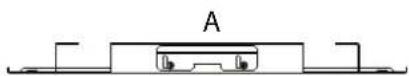

natural_image
Technical line drawing of a rectangular electronic component with mounting holes and internal structure (no text or symbols)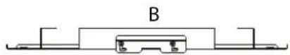
6.2 METTERE L'UNITÀ IN TENSIONE
natural_image
Technical line drawing of a mechanical component with no visible text or symbols1 Scarico condensa
»Fig.16
natural_image
Technical line drawing of a mechanical component with labeled parts (no text or symbols present)1 Scarico condensa
» Fig.18 FWH-A 06-07-08

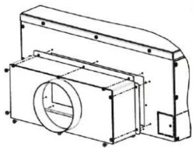
8.5 COLLEGAMENTO MANDATA ARIA IN LOCALI ATTIGUI
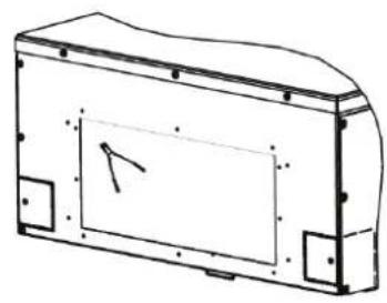
natural_image
Technical line drawing of a mechanical housing or enclosure with mounting holes and a central panel (no text or symbols)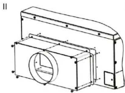
natural_image
Technical line drawing of a mechanical housing or enclosure with internal components and mounting holes (no text or symbols)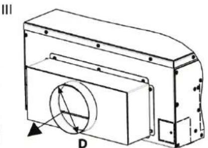
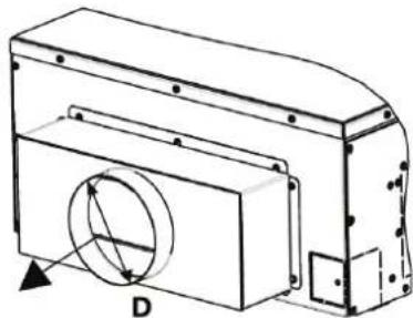
natural_image
Technical line drawing of a mechanical component with labeled dimension D (no text or symbols beyond label)9MANUTENZIONE
9.2 PULIZIA GRIGLIA DI ASPIRAZIONE FPAN
9.3 PULIZIA DEL FILTRO ARIA GRIGLIA FCND02A
9.4 PULIZIA DEL PANNELLO DI CHIUSURA DELLA GRIGLIA FCND02A
9.7 LIVELLO ACQUA ANOMALO
10 RICERCA DEI GUASTI
3.1 AVAILABLE VERSIONS ...... p. 30 Accessories supplied with the unit...... p. 30
3.2 MAIN COMPONENTS.... p. 31 Structure.... p. 31 Air filter.... p. 31 Heat exchanger.... p. 31 Fan drive assembly.... p. 31 Condensate collection system.... p. 31 Condensate discharge system.... p. 31 Grille FPAN.... p. 31 Grille FCND02A.... p. 31
3.3 ACCESSORIES.... p. 31
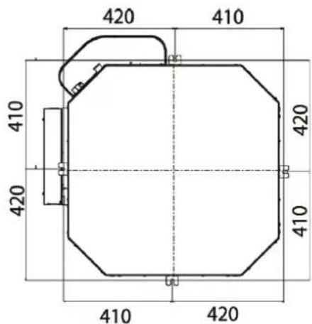
4 DIMENSIONS p. 32
5 INSTALLATION...... p. 32
5.1 INSTALLATION REQUIREMENTS.... p. 32 Electrical connections.... p. 33 Control dedicated (FWEC2T/4T - FWECSA - FWEC1A-2A-3A.... p. 33 Hydraulic connections.... p. 33 Condensate drain connections.... p. 29
5.2 DIMENSIONAL UNIT ASSEMBLY ..... p. 34 Front panel/grille assembly FPAN ..... p. 36 Front panel/grille assembly FCND02A ..... p. 32
6 CHECKS BEFORE STARTUP.... p. 37
6.1 PRELIMINARY CHECKS.... p. 37 6.2 SWITCH ON THE UNIT.... p. 38 6.3 FILL THE WATER CIRCUIT.... p. 38 6.4 ADJUSTING THE AIR FLOW.... p. 38
7 USE p.38
8 ACCESSORIES.... p. 39
8.1 2- OR 3-WAY MOTOR-DRIVEN VALVE KITS ..... p. 39
8.2 PRESSURE-INDEPENDENT MOTOR-DRIVEN 2-WAY VALVE KIT ...... p. 39
8.3 AUXILIARY WATER DRIP TRAY FOR COLLECTING CONDENSATE FROM THE CONTROL VALVES.... p. 39
8.4 CONNECTION FOR INTAKE OF FRESH AIR TO BE TREATED.... p. 40
8.5 CONNECTION FOR OUTLET OF AIR IN ADJACENT ROOMS p. 40
9 MAINTENANCE p. 41
9.1 CLEANING THE AIR FILTER FPAN GRILLE ..... p. 41
9.2 CLEANING THE AIR INTAKE FPAN GRILLE..... p. 41
9.3 CLEANING THE AIR FILTER FCND02A GRILLE.. p. 37
9.4 CLEANING FCND02A GRILLE OVER PANEL .... p. 37
9.5 ELECTRIC CONTROL BOARD p. 42
9.6 ADDITIONAL MAINTENANCE ...... p. 42
9.7 ABNORMAL WATER LEVEL.... p. 43
10 TROUBLESHOOTING p. 43
11 RATED TECHNICAL DATA p. 44
12 ELECTRICAL WIRING DIAGRAM LEGEND p. 47
12.1 SPECIFIC FOR WIRING DIAGRAMS WITH FWECSAP CONTROL.... p. 47
13 FIGURES p. 168
1 BEFORE STARTING THE INSTALLATION PROCEDURE
TRANSLATION BY ORIGINAL INSTRUCTIONS
Carefully read this manual.
Installation and maintenance should be carried out by technical personnel qualified for this type of machine, in compliance with current safety regulations.
When receiving the unit please check its state verifying if any damage occurred during the transport.
For installation and use of possible accessories please refer to the pertinent technical sheets.
The manual are subject to changes, in any times, without prior notice aimed at improving the product.
Identify the model of the FWH-A cassette fan coil following the indications on the packing container.
SAFETY SYMBOLS
| i | Carefully read this manual. |
| Warning | |
| Use personal protective equipment |
USE APPROPRIATE PPE (GLOVES, PROTECTIVE GOGGLES)
WARNING: electrical and electronic products may not be mixed with unsorted household waste. Do NOT try to dismantle the system yourself: the system must be dismantled by an authorised installer and must comply with applicable legislation. Units must be treated at a specialized treatment facility for reuse, recycling, and recovery. By ensuring that this product is disposed of correctly, you will help to prevent potential negative consequences for the environment and human health. For more information, contact your installer or local authority.
DANGER: The unit may be used by children of at least 8 years of age and by persons with reduced physical, sensory, or mental capabilities, or who lack experience or the necessary knowledge, provided that they are supervised or after they have received instructions relating to the safe use of the unit and understand the inherent dangers. Children must not play with the unit. Cleaning and maintenance to be carried out by the user must not be performed by unsupervised children.
WARNING: Before performing any work on the unit, ensure it has been disconnected from the power supply.
WARNING: unit installation and start-up must be entrusted to competent personnel and performed in a workmanlike manner, in accordance with current regulations.
2 INTENDED USE
DAIKIN will not accept any liability for damage or injury caused as a result of installation by non-qualified personnel; improper use or use in conditions not allowed by the manufacturer; failure to perform the maintenance prescribed in this manual; use of spare parts other than original factory parts.
Equipment designed for ambient air conditioning and intended for use in civil comfort applications.
INSTALLATION SITE
When choosing an installation site, you should observe the following rules:
— install the unit indoor only
— Do not install the unit in a room containing flammable, alkaline, acidic, oily, or very humid air, nor in one where water may be projected (e.g. laundry room). The components would be irreparably damaged.
— choose the most central position of the room.
— do not install the unit where excessively high heat-generating equipment is located
— make sure that in the chosen location nothing will obstruct the system and its maintenance (beams, insufficient suspended ceiling height, suspended ceiling panels that cannot be removed, difficult access for maintenance, etc.).
— it is the customer's responsibility to provide safe access to the base unit, on the sides where there is an electrical box
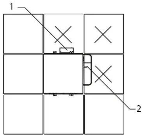
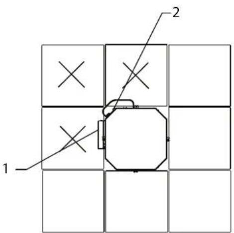
and water connections, to ensure the proper execution of routine and extraordinary maintenance operations. In case of installation in modular suspended ceilings, it is necessary to provide access to the panels shown in figures p. 25
— the minimum installation space between the structural ceiling and the suspended ceiling is:
| Model Distance [mm] | |
| FWH-A 02-03-04 310 | |
| FWH-A 06-07-08 360 |
— the maximum dimensions of the opening to be made in the suspended ceiling to house the fan coil unit are as follows:
| Model MAX. dimensions [mm] | |
| FWH-A 02-03-04 690x690 | |
| FWH-A 06-07-08 820x820 |
— do not use or store petrol or other flammable liquids near the unit. It is very dangerous.
— do not install electrical equipment that is not protected with IPX1 degree of protection (protection against vertical water drop) underneath the unit.
— The manufacturer assumes no responsibility if safety and accident prevention regulations are not observed.
Note: the diffusion of air will not be as efficient if the room is more than 3 metres high.
» Installation FWH-A 02-03-04
1 Electric box
2 Water connections
» Installation FWH-A 06-07-08
1 Electric box
2 Water connections
OPERATING LIMITS
Thermal carrier fluid: water
Water temperature: 5°C ÷ 80°C
Air temperature: 5^ ÷ 43^
Supply voltage: 230 V - 50 Hz
Maximum water pressure during operation: 10 bar
Relative humidity limit of the ambient air:RH < 75% not condensing
3 UNIT DESCRIPTION
Comfort, low noise, and efficiency in perfect harmony!
The new series of hydronic cassette units FWH-A, with ON/OFF motor, consists of 6 models (02-03-04-06-07-08) for 2-pipe systems and 5 models (02-03-04-06-08) for 4-pipe systems.
The engineering of the unit makes it possible to develop up to 5 kW in the cooling mode in a standard 600x600 mm modular suspended ceiling and over 9 kW in the 860x860 mm modularity, with exceptionally low noise levels in the phases for maintaining interior comfort.
FWH-A leverages the entire DAIKIN FWEC1A/FWEC2A/FWEC3A, FWECSA and FWEC2T/4T microprocessor controller platform that incorporate sophisticated adjustment logics based on air temperature, air humidity, and water temperature.
These benefits translate into greater accuracy in achieving and maintaining the desired comfort conditions through appropriate modulation of the fan speed as well as the reduction of noise emissions, which adapt to the actual thermal load.
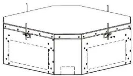
The suspended ceiling unit houses all the components, heat exchange coil, fan drive assembly, and condensate collection and drainage system. Its structure is designed for introducing fresh air into the space, mixing it with recovered air, and distributing the treated air from the cassette unit to adjacent rooms.
Two tipes of intake and oulet air grilles:
FPAN grill: ABS material, available in RAL9003 guarantee optimal integration into the suspended ceiling panels.
With easy access to air filter for cleaning operations.
The unit can be supplied complete with valves, including pressure-independent balancing and control valves, the use of which significantly reduces commissioning time.
FCND02A gille : design grille with Coandă effect: DIBOND material, thanks to Coandă effect, the air is expelled parallel to the ceiling, cooling the walls before mixing with the ambient air at the ground. In this way the operation will be optimized during the summer, ensuring more comfort for the occupants.
3.1 AVAILABLE VERSIONS
FWHO*ATN - Unit with one coil for 2-pipe systems
FWHO*AFN - Unit with one coil for 4-pipe systems
Accessories supplied with the unit
— Auxiliary water drip tray;
— Installation and use manual;
— Brackets for securing the unit.
3.2 MAIN COMPONENTS
Structure
Made of galvanised steel sheet with internal polyurethane foam coating and external fl ocked PES to guarantee heat and sound insulation. Fresh air can be introduced into the room directly through the unit due to the provision of connections for neutral or mixed introduction. Accessories are available for connection to ducts. There are systems on the unit for anchoring it to the ceiling. The electrical wiring is housed in a containment box and is easily accessible from the side for easy connection.
Airfilter
Honey-comb polypropylene washable air filter, easily removable for maintenance operations.
Heatexchanger
Copper pipe and high efficiency aluminium fins secured to the pipe by mechanical expansion. With at least two rows in the models for 2-pipe systems, it is available in the 2+1 configuration in the models for 4-pipe systems. The coil comes complete with manual air vent valves. On request, valves can be connected to the coil to regulate and balance the operation of the unit.
Fan drive assembly
Multi-speed ON/OFF electrical motor, directly connected to a centrifugal fan with backward-curving blades with profi le optimised for stable operation at all speeds.
Condensate collection system
Located under the heat exchanger, the main drip tray is made of polystyrene and is inserted inside the profi les optimised for the distribution of air in the room. The supply is completed by the auxiliary water drip tray for the collection of condensate from the regulating valves.
Condensate discharge system
The condensate drainage pump, with built-in check valve, can lift the condensate up to 0.9 m from the exit point from the unit. The operation of the pump is controlled by a fl oat switch with three levels of action that activate it and stop it during normal operation. If the critical water level inside the main drip tray is
exceeded, an alarm signal closes the control valves, stopping the flow of water inside the exchanger.
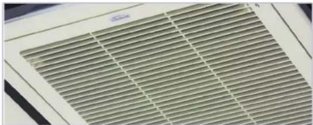
FPANgrille
It is square shaped for the intake and diffusion of air in the space, and it is made of ABS, colour RAL9003. The air intake louvre can be opened for access to the air filter. Air is diff used in the space through the 4 sides, each of which is equipped with an adjustable fin with suitable thermal insulation.
natural_image
Close-up of a ventilation grille with uniform grating pattern (no text or symbols visible)FCND02A grille: design grille with Coandă eff ect
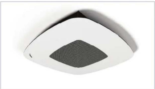
It is square shaped with circle intake hole, it is made in DIBOND material. The intake grille is opened for access to the air fi Iter. Air is diff used in the space through the conveyors in 4 sides and takes advantage of the fluid dynamic Coandä effect.
Thanks to Coandă eff ect, the air is expelled parallel to the ceiling, cooling the walls before mixing with the ambient air at the ground. In this way the operation will be optimized during the summer, ensuring more comfort for the occupants.
natural_image
Close-up of a modern ceiling-mounted air conditioner unit with a mesh grille and vent, mounted on a white panel (no text or symbols visible)3.3 ACCESSORIES
Electronic microprocessor control panels with display
| FWTOUCH 2.8" | touch screen user interface for FWECSA control | |
| FWECSAP Circuit board for FWECSA control | ||
| FWECSAC | User interface with display for FWECSA controller | |
| FWEC1A | FWEC1A electronic controller with display | |
| FWEC3A | Microprocessor control with display FWECSA | |
| FWEC2A | FWEC2A electronic controller with display | |
| FWHSKA | Humidity sensor for FWEC (2A e 3A), FWECSA | |
| FWTSKA | Water sensor for FWECTA-2A-3A and FWECSA controllers | |
| Electronic microprocessor control panels | ||
| FWEC2T Electronic controller for AC fan control and one ON/OFF 230 V valve | ||
| FWEC4T Electronic controller for AC fan control and two ON/OFF 230 V valves | ||
| Power interface and regulating louver controllers | ||
| EPIMSB6 | Power interface for connecting in parallel up to 4 fun coil units to the one controller | |
| Valves | ||
| E2C2PIC/PRP E4C2PIC/PRP | PRESSURE-INDEPENDENT 2-way valves for models with 1 or 2 coils | |
| E2C2 | 2-way valve, ON/OFF or MODULATING actuator, 230 V or 24 V power supply, hydraulic kit, for model with 1 or 2 heat exchangers | |
| E2C3 | 3-way valve, ON/OFF or MODULATING actuator, 230 V or 24 V power supply, hydraulic kit, for model with 1 or 2 heat exchangers | |
| Plenum, air intake modules, air inlet and outlet connectors and cabinets | ||
| SPFAI1A/ SPFAI2A | Spigot for introduction of mixed renewal air | |
| PPAI0ZA/6A | Air outlet plenum | |
In figures p. 170 and p. 169 shows the dimensions of FWH-A and shows the position of water connections.
5 INSTALLATION
WARNING: It is mandatory to install the 3-way (or 2-way) valve accessory in order to avoid the circulation of cold water in the exchanger if the unit is not operated for long periods of time, with the fan off. Install the auxiliary water drip tray, provided together with the base unit, in order to prevent valve kits from dripping.
For each unit an (IL) switch should be mounted on the power supply, with opening contacts at a distance of at least 3 mm and a suitable protection fuse (F).
WARNING: before carrying out any operation, check that the voltage and frequency of the unit correspond exactly to those of the main power supply.
WARNING: Install the unit, circuit breaker (IL) and/or any remote controls in a place out of reach of persons who may be taking a bath or shower.
WARNING: keep the unit's grille in its original packaging until final assembly.
RECOMMENDED: to ensure optimal comfort (homogeneous air temperature in the room), it is recommended not to exceed a heat exchanger water inlet temperature of 55 °C.
WARNING: during a shutdown for installation, in the event of a connection to a fresh air intake or an ambient temperature close to 0 °C, there is a risk of the pipes freezing. Provide drainage for the water circuit.
WARNING: Install the unit without providing slopes; for a correct condensate drainage there is a slope in the condensate drip tray inside the unit.
5.1 INSTALLATION REQUIREMENTS
The fan coils should be installed in a position where the room can be heated or cooled evenly, on ceilings able to support their weight. Store the unit in its packaging until you are ready to install it.
For installation and use of accessories, please refer to the relative technical sheets.
Install any remote control panel in an easily accessible position allowing the user to set the functions while ensuring an accurate reading of the ambient temperature, if provided.
Avoid therefore:
— positions directly exposed to sunlight;
— positions exposed to direct currents of warm or cold air
—placing obstacles that impede an accurate temperature reading
During continuous winter operation, to avoid problems relating to the regulation of the unit, it is recommend to use remote controls supplied with a probe for detecting the air temperature.
NB: The water sensor, where present, must be mounted in the appropriate trap on the valve kit, on the INLET pipe.
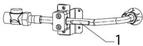
natural_image
Technical line drawing of a mechanical assembly with no visible text or symbols1 Water sensor holder
— If a valve kit other than the one suggested is used, it is necessary to install the sensor on the INLET pipe, by means of the special copper socket filled with conductive paste.
— Lastly, the sensor must be properly isolated to ensure that it reads the water temperature correctly.
NB: The air and humidity sensors, where present, must be attached in the appropriate section located in the intake area of the base unit. Sensor retainer and relative fixing screws are supplied with unit.
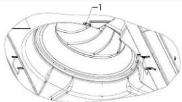
1 Sensor retainer
Make the plumbing connections to the heat exchanger and, where the cooling function is to be used, to the condensate drainage outlet.
WARNING:
In normal operation, particularly with the fan at minimum speed and ambient air with high relative humidity, condensation may form on the air outlet and on some external parts of the unit.
To avoid such issues while always remaining within the operating limits envisaged for the unit, it is necessary to limit the inlet temperature of the water inside the heat exchanger. In particular, the difference between the air dew point ( T_A, D_P ) and the inlet water temperature ( T_W ) must NOT exceed 14 °C, according to the following relationship:
TW>TA,DP-14°C
Example: in the case of ambient air at 25^ C with 75% relative humidity, the dew point temperature is about 20^ C and therefore the inlet temperature of the water in the battery must be greater then:
— 20-14 = 6 °C in order to avoid condensation on a fancoil equipped with a valve.
Fan coil with valve
| Air temperature dry bulb (°C) | ||||||||
| 21 23 | 25 27 | 29 31 | 33 | |||||
| Relative humidity % | 40 55 55 55 5 | |||||||
| 50 55 55 56 8 | ||||||||
| 60 55 55 79 11 | ||||||||
| 70 55 68 91 13 | ||||||||
| 80 56 810 12 14 16 | ||||||||
| 90 68 10 12 14 16 18 | ||||||||
If the valves are not installed, there could be abundant condensation, especially if the unit is not operated for long periods of time.
During wintertime periods of quiescence, drain water from the system, to prevent ice from forming. If anti-freeze solutions are used, check for their freezing point using the table below.
| % Glycol by weight | Freezing temperature (°C) | Capacity adjustment | Pressure drop adjustment |
| 0 0 1,00 1,00 | |||
| 10 - 4 0,97 1,05 | |||
| 20 - 10 0,92 1,10 | |||
| 30 - 16 0,87 1,15 | |||
| 40 - 24 0,87 1,20 |
Electrical connections
Make the electrical connections whilst the power supply is disconnected, in accordance with current safety regulations, carefully following the wiring diagram and its legend.
Check that the mains electricity supply is compatible with the voltage shown on the unit rating plate.
NOTE: The electrical connections indicated must be made by the installer.
For each fan coil a switch (IL) should be mounted on the power supply, with opening contacts at a distance of at least 3 mm and a suitable protection fuse (F).
For the electrical connections of the controls, follow the diagrams in the figures from: p. 175.
WARNING! Cassette is predisposed for standard control FWEC1A-2A-3A, for FWEC2T disconnect the gray wire of the float from terminal 4 and connect to free terminal 8, remove the blue bridge between terminals N and 4, then complete the connections of the FWEC2T to the terminal board as in the wiring diagrams:
— p. 178 for FWH-A 02-03;
— p. 179 for FWH-A 04;
— p. 180 for FWH-A 06-07-08;
CASSETTE is predisposed for standard control FWE-C1A-2A-3A, for FWEC4T disconnect the gray wire of the float from terminal 4 and connect it through a flying terminal to terminal 3 of the FWEC4T, remove the blue bridge between terminals N and 4, then complete the connections of the FWEC4T to the terminal board as in the wiring diagrams:
— p. 181 for FWH-A 02-03;
— p. 182 for FWH-A 04;
— p. 183 for FWH-A 06-07-08;
WARNING: The power supply to the pump-float switch device must never be interrupted.
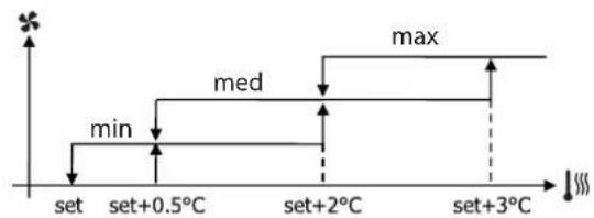
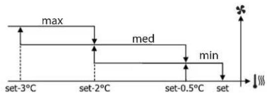
Control dedicated (FWEC2T/4T - FWECSA - FWEC1A-2A-3A
Controls implement a logic that makes it possible to set a fixed speed between minimum, medium and maximum, or automatic speed modulation.
The automatic logic varies the analog signal to the motor between minimum, medium and maximum speed, based on the distance from the set-point, in order to accelerate the implementation phases.
»Cooling
» Heating
Hydraulic connections
| Unit | Exchanger connection | |
| FWH02ATN,FWH03ATN,FWH04ATN(2 pipes) | 1/2" gas F | |
| FWH06ATN,FWH07ATN,FWH08ATN (2 pipes) | 3/4" gas F | |
| Cooling | Heating | |
| FWH02AFN,FWH03AFN,FWH04AFN (4 pipes) | 1/2" gas F | 1/2" gas F |
| FWH06AFN,FWH08AFN (4 pipes) | 3/4" gas F | 1/2" gas F |
To optimise performance, it is advisable to make the following connections on the exchanger:
— Unit outlet: connection below.
— Unit return: connection above.
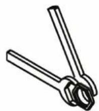
WARNING: While making the connections, hold the water connections of the unit tightly in place with a hexagonal wrench or make sure that they do not rotate, in order to prevent the pipes inside the unit from being damaged.
natural_image
Line drawing of two crossed metal tools (no text or symbols)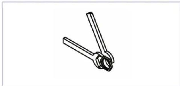
natural_image
Line drawing of two metal clamps (no text or symbols)— Carefully insulate the inlet and outlet water pipes as well as
the devices installed in the network (on/off valves...). Use a material that is suitable for the operating conditions and water temperature.
— Bleed air from the exchanger by means of the air vent valves located next to the water connections of the coil. Depending on the installation, it may be necessary to place other vent valves on the hydraulic system.
Condensate drain connection
Connect a rigid PVC pipe to the end of the hose and secure it with a clamp
Correctly insulate the pipe with polyethylene foam.
— Be careful of the risk of freezing in winter in suspended ceilings.
— If necessary, the condensate pipe can be routed immediately after the unit's outlet. Maximum height: 900 mm (FIGURE 1).
— Make sure that the drainpipe has a slight slope in the direction of flow and that it does not form a siphon (FIGURE 1).
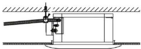
— The piping must have several supports (FIGURE 2).
— Do not install an air vent (FIGURE 3) in the wrong position.
»Fig.1
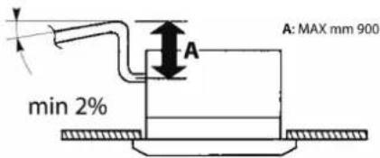
»Fig.2
natural_image
Technical line drawing of a mechanical assembly with no visible text or symbols»Fig.3

natural_image
Pure mechanical diagram showing a lever and base with no text or symbols5.2 DIMENSIONAL UNIT ASSEMBLY
— Use the dimensional drawings to determine the position of the suspension rods (Fig.4 FWH-A 02-03-04) (Fig.5 FWH-A 06-07-08)
— Position the suspension rods (not supplied) in place.
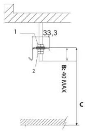
— Attach the supplied brackets (Fig.6) to the suspension rods (Fig.7). The length of the suspension rods depends on the space between the suspended ceiling and the structural ceiling.
— The distance C (Fig.7) must be:
| Model | C- Bracket distance to the false ceiling |
| FWH-A 02-03-04 270 | |
| FWH-A 06-07-08 312 |
— Pay attention to the excess length B of the suspension rod (Fig.7): it may interfere with the unit's electrical box.
— Place the fan coil unit in the suspended ceiling, orienting the side with the water connections in the most appropriate position, using the hooks on the brackets to provide quick temporary installation.
— Then attach the unit to the threaded bars with the screws provided and check that it is level (Fig.8)
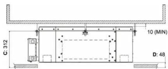
— Adjust the distance between the unit and suspended ceiling D (Fig.9 FWH-A 02-03-04 and Fig.10 FWH-A 06-07-08) using the nuts of the suspension rods:
| Model | D - Distance from unit to false ceiling |
| FWH-A 02-03-04 23 | |
| FWH-A 06-07-08 48 |
— Make sure that the unit does not touch the ceiling: contact may cause noise.
— Insulate the brackets (fig. 6) fixed on the unit with the insulation supplied.
» Fig.4 FWH 02-03-04
»Fig.7
- Nut + washer
- Washer + nut + lock nut
» Fig.5 FWH 06-07-08
»Fig.8
natural_image
Technical line drawing of a hexagonal mechanical housing or enclosure with mounting holes and internal compartments (no text or symbols)» Fig.9 FWH 02-03-04

»Fig.6

»Fig.10
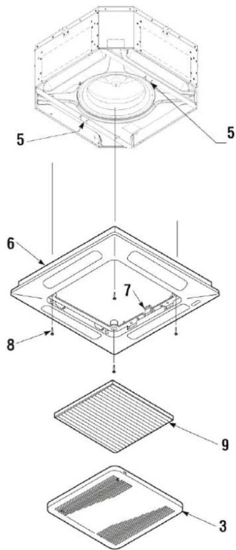
Front panel/FPAN grille assembly
The front panel/grille, available in RAL9003, is delivered in a separate cardboard box:
— FPAN02 for models FWH-A 02-03-04
— FPAN06 for models FWH-A 06-07-08
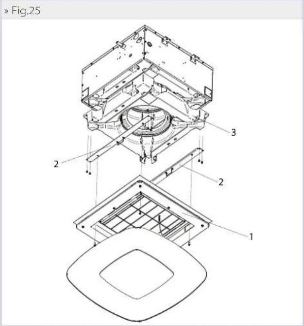
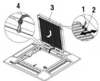
Before installing the front panel: (Fig.11)
— Remove the screws (1) securing the retainers (2) on each side (remember to put these screws back in place after installation).
— To open the grille (3), move the two retainers (2) in the direction of the arrow.
— Open the grille (3) by 45°.
— Detach the control panel's safety cable (4) (remember to attach it again after installation).
— Lift the grille to remove it from the control panel.
»Fig.11
To install the front panel: (Fig.12)
— Turn the two locking clips (5) downwards.
— Attach the control panel of the panel (6) to the unit by means of the two hooks (7), matching them to the locking clips (5).
— Check the exact position of the panel's control panel in relation to the suspended ceiling. Adjust the position of the indoor unit as necessary.
— Attach the panel's control panel to the unit using the special screws and washers (8) provided.
— Put the grille (3) in place, making sure that the filter (9) is correctly positioned.
— Hook the safety cable to the control panel, close the grille, and put the screws securing the retainers (2) back in place.
»Fig.12
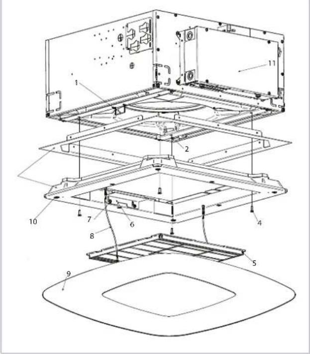
Front panel/grille FCND02A assembly
The front panel/grille, available for FWH 02-03-04 versions, is delivered in a separate cardboard box:
To install the panel (Fig.13):
— Turn the two locking clips (1) downwards.
— Attach the panel body (3) with appropriate screws (4) at the inserts (2) already present on it.
— For the correct fixing of panel group (3) align one of the sides with filter fixing bracket (6) to the sides with electrical box (11).
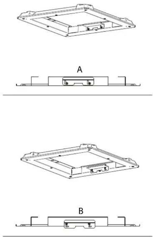
— To install the filter, unscrew slightly the fixing screws (7) of support brackets (6).
— From position (A), move the two brackets (6) horizontally first and then vertically along "L" guides, to move the screws (7) to position (B).
— Pass the filter through the cleared area by the movement of brackets and block it by reversing the procedure to the point above, then replace the screws (7) in position (A) and tighten them.
— Place the covering panel (9) hooking up safety cables first (8) to the clip (1) and then join the panel with unit (3) through magnets (10) on 4 sides.
»Fig.13
6 CHECKS BEFORE STARTUP
6.1 PRELIMINARY CHECKS
Make sure:
— make sure that the power cable is not damaged, if it is damaged must be replaced by the manufacturer or its technical assistance service or in any case by a person with a similar qualification, in order to prevent any risk,
— that the unit is stable and perfectly level,
— that the electrical cables are well tightened on their terminal
blocks (if they are not tightened properly, the terminals may cause the terminal block to overheat),
— that the electrical cables are properly insulated from any sheet metal or metal parts that could damage them,
— that the unit is well earthed,
— that no tools or any other foreign objects have been left in the unit,
— that the filter is properly installed,
— that the coil is clean,
— that the hydraulic fittings are properly tightened,
— that the condensate drain is properly connected and not obstructed,
— that the condensate drain pan is clean,
— that the drainage pipes are securely fastened.
6.2 SWITCH ON THE UNIT
— Using an isolation and protection device.
— Start the unit using the controller.
— Start-up should be carried out at the maximum operating speed.
— A running in period of 100 hours is necessary to eliminate all initial mechanical friction of the motor.
6.3 FILL THE WATER CIRCUIT
— Ensure operation of the motor-driven valve by operating it via the remote control.
— Check that all the connections are watertight.
— Check the operation of the condensate drainage pump by pouring a little water into the auxiliary water drip tray located under the valve.
— Check that there is no water backflow when the pump is stopped.
— Purge the air from the cassette's heat exchanger.
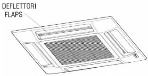
6.4 ADJUSTING THE AIR FLOW (ONLY FOR FPAN GRILLE)
You can adjust the air flow direction using the 4 fl aps on the front panel.
Choose the position according to the operating mode and the recommended inclination: the position of the fl aps must be adjusted manually. (Fig.14 and Fig.14.1)
»Fig.14
»Fig.14.1
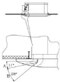
A. Cooling and dehumidification zone
B. For the heating of zones
7USE
This unit is intended for the air conditioning of rooms for the maximum well-being of people. Designed for room air conditioning and intended for residential comfort applications.
To use the fan coil refer to the instructions on the control panel available as accessory.
ATTENZIONE: For safety reason, do not introduce your fingers or other pointed objects in the air outlet grilles.
DANGER: The unit may be used by children of at least 8 years of age and by persons with reduced physical, sensory, or mental capabilities, or who lack experience or the necessary knowledge, provided that they are supervised or after they have received instructions relating to the safe use of the unit and understand the inherent dangers. Children must not play with the unit. Cleaning and maintenance to be carried out by the user must not be performed by unsupervised children.
8 ACCESSORIES
8.1 2- OR 3-WAY MOTOR-DRIVEN VALVE KITS
WARNING: The installation of a valve kit on the fan coil unit is mandatory FWH-A.
The kit is made up of:
— Brass 2- or 3-way valve with 4 connections with built-in bypass, maximum operating pressure 16 bar.
— Electrothermal actuator with 230 V or 24 V power supply, ON/OFF (or modulating) function, total opening time 3 minutes.
— Hydraulic kit with O-ring for connection with the exchanger and paper gasket for connection with the valve
— Brackets for fastening the hydraulic kit on the side of the unit in order to ensure stability during transport if the valves are already installed.
Unit Valve type Connection Kvs straight Kvs by-pass
| FWH02ATN,FWH03ATN,FWH04ATN(2 pipes) 3-way 3/4" M 2,5 | 1,6 |
| FWH06ATN,FWH07ATN,FWH08ATN(2 pipes) 3-way 3/4" M 4 | 1,6 |
| Cooling | Heating | ||||||
| Unit | Valve type | Connection | KVS direct way | Kvs by-pass | Connection | KVS direct way | Kvs by-pass |
| FWH02AFN,FWH03AFN,FWH04AFN (4 pipes) | 3-way | 3/4"M | 2,5 | 1,6 | 3/4"M | 2,5 | 1,6 |
| FWH06AFN,FWH08AFN (4 pipes) | 3-way | 3/4"M | 4 | 1,6 | 3/4"M | 2,5 | 1,6 |
| Unit | Valve type | Connection | KVS | ||||
| FWH02ATN,FWH03ATN,FWH04ATN (2 pipes) | 2-way | 3/4"M | 2,8 | ||||
| FWH06ATN,FWH07ATN,FWH08ATN (2 pipes) | 2-way | 3/4"M | 4 | ||||
| Cooling | Heating | ||||||
| Unit | Valve type | Connection | KVS | Connection | KVS | ||
| FWH02AFN,FWH03AFN,FWH04AFN (4 pipes) | 2-way | 3/4"M | 2,8 | 3/4"M | 2,8 | ||
| FWH06AFN,FWH08AFN (4 pipes) | 2-way | 3/4"M | 4 | 3/4"M | 2,8 | ||
NOTE: for units FWH-A it is necessary to install the 3-way valves inclined so as to comply with the space constraint regarding the height of the base unit.
The valve kits are shown in the figures from page: p. 205. Pressure drops of the valve/hydraulic kit assembly are calculated using the following formula:
$$ \Delta P _ {W} = \left(Q _ {W} / K _ {V}\right) ^ {2} $$
Where:
P_w= pressure drop in bar
Q_w= water flow rate in m³/h
K_v = water flow rate coefficient of the valve obtained from the table
8.2 PRESSURE-INDEPENDENT MOTOR-DRIVEN 2-WAY VALVE KIT
WARNING: The installation of a valve kit on the fan coil unit is mandatory FWH-A.
The pressure-independent 2-way valve kit consists of:
— 2-way valve with maximum operating pressure of 16 bar.
— Electrothermal actuator with 230 V or 24 V power supply, ON/OFF (or modulating) function, total opening time 3 minutes.
| Unit | Valve type |
| FWH02ATN,FWH03ATN, FWH04ATN (2 pipes) | 2-way |
| FWH06ATN,FWH07ATN, FWH08ATN (2 pipes) | 2-way |
| Unit | Valve type |
| FWH02AFN,FWH03AFN,FWH04AFN (4 pipes) | 2-way |
| FWH06AFN,FWH08AFN (4 pipes) | 2-way |
— Hydraulic kit with O-ring for connection with the exchanger and paper gasket for connection with the valve.
— Brackets for fastening the hydraulic kit on the side of the unit in order to ensure stability during transport if the valves are already installed.
The valve kits are shown in the figures on page: p. 209 and p. 210.
| Connection | p min [kPa] |
| 3/4"M | 32 |
| 1 1/4"M | 20 |
| Cooling | Heating | ||
| Connection | p min [kPa] | Connection | p min [kPa] |
| 3/4"M | 16 | 3/4"M | 16 |
| 1 1/4"M | 20 | 1"M | 16 |
8.3 AUXILIARY WATER DRIP TRAY FOR COLLECTING CONDENSATE FROM THE CONTROL VALVES
The auxiliary water drip tray is supplied with the base unit together with two fastening screws.
Its function is to collect the condensate generated by the control valves and to convey it inside the main condensate drip tray of the unit. (FIGURE 15, FIGURE 16)
»Fig.15
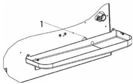
natural_image
Technical line drawing of a mechanical component with no visible text or symbols1 Condensate discharge
»Fig.16
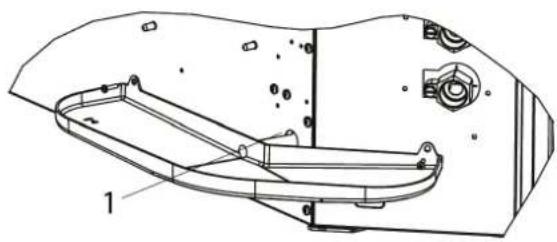
natural_image
Technical line drawing of a vehicle chassis frame with labeled components (no text or symbols present)1 Condensate discharge
WARNING: The installation of the auxiliary water drip tray is mandatory.
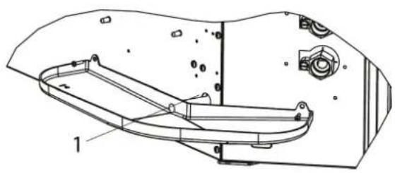
8.4 CONNECTION FOR INTAKE OF FRESH AIR TO BE TREATED
The units are equipped with 3 fresh air inlets, positioned in the corners. This air mixes with the air drawn in from the indoor environment and is then treated by the heat exchanger. (Fig. 17 - Fig. 18)
— The SPFAI1A (FWH-A 02-03-04) and SPFAI2A (FWH-A 06-07-08) accessory is available: a fitting for ∅100 pipe to be connected to the inlets located on the unit.
— It is necessary to filter the fresh air before introducing it in the unit, making sure that its temperature is not too low.
— To avoid operating and noise-related problems, the fresh air flow rate is limited to 20% of the unit's air flow at average speed, with a maximum of 110 m^3/h for each intake.
WARNING: It is necessary to prevent the intake of dust and impurities that could foul the unit's exchanger.
» Fig.17 FWH-A 02-03-04
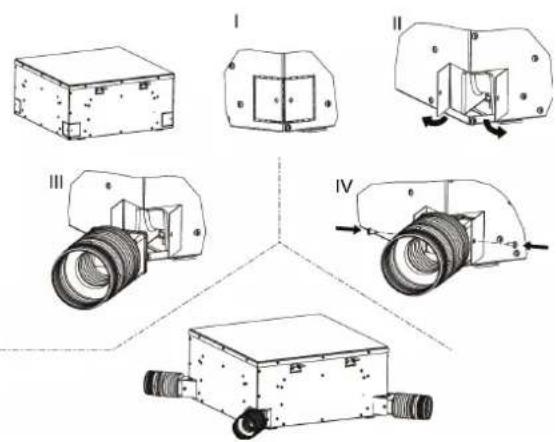
» Fig.18 FWH-A 06-07-08

8.5 CONNECTION FOR OUTLET OF AIR IN ADJACENT ROOMS
The units are equipped with 2 rectangular air outlets for connection to separate distribution ducts.
— These outlets are located on the sides not occupied by the electrical box and water connections.
— The PPAI02A/6A accessory is available: a plenum to connect the rectangular outlets located on the unit to the round distribution ducts with diameter D:
| Model D | |
| FWH-A 02-03-04 150 | |
| FWH-A 06-07-08 180 |
WARNING: The air ducts from the fan coil unit must be thermally insulated to prevent the formation of surface condensation.
» PPA102A/6A
|
natural_image
Technical line drawing of a rectangular electronic component with mounting holes and internal cavity (no text or symbols)||
natural_image
Technical line drawing of a mechanical housing or enclosure with internal components and mounting holes (no text or symbols)III
natural_image
Technical line drawing of a mechanical housing or enclosure with a circular component and mounting holes (no text or symbols)9MAINTENANCE
For safety reasons, before carrying out any maintenance or cleaning jobs, turn off the unit by moving the fan speed selector to "OFF" and putting off the main switch 0 (OFF). Any work must be carried out by personnel qualified and authorised to work on this type of unit.
⚠️ DANGER! Due caution must be taken while carrying out maintenance: some metal parts may cause injuries; wear protective gloves.
The material must undergo maintenance in order to retain its characteristics over time. Lack of maintenance may have the effect of voiding the product warranty. The operations consist of cleaning the air fi Iter, the internal and external exchangers, the cabinet, and cleaning and protecting the condensate drip trays. Odour treatment and disinfection of the surfaces and spaces also contribute to the healthiness of the air breathed by users. Whenever starting up the unit after it has not been used for a long time, check that there is no air in the heat exchanger. Before the period of operation in the cooling mode, check that condensate is properly drained.
Adequate periodic maintenance will ensure save both energy and cost savings.
9.1 CLEANING THE AIR FILTER FPAN GRILLE
Clean the air fi liter at least once a month and in any case at the start of the period of use (before the heating and the air conditioning season).
For fi Iter cleaning, proceed as follows (Fig.21):
-
Before performing any work on the unit, disconnect it from the power supply.
-
Remove the screws (1) securing the retainers (2) on each side.
-
To open the grille (3), push on the two retainers (2) in the direction of the arrow.
-
Open the grille (3) downwards.
-
Remove the filter (4) from the grille.
-
Use a vacuum cleaner to remove dust. If dust is glued to the filter, remove it with clean or soapy water, rinse the filter with clean water and dry it.
-
Put the fi Iter back into its place in the grille, close the grille, moving the two retainers outwards, then put the screws securing the retainers back in place.
It is recommended to replace the air filter once a year, using an
original replacement fi liter; the indoor unit model can be found on the identification plate located on the tank inside the unit, behind the air fi liter.
»Fig.21

9.2 CLEANING THE FPAN AIR INTAKE GRILLE
The grille can be removed for cleaning. (Fig.22)
— After opening the grille (5), detach the safety cable (6) of the control panel (7) (remember to attach it again after maintenance and cleaning).
— Lift the grille and pull it towards you to release the two hinges
— Clean the grille gently using a soft sponge, then dry well. A neutral detergent can be used to remove difficult residues. Rinse well with water, then dry.
— Never use harsh chemical solvents.
— Do not use excessively hot water to clean the unit.
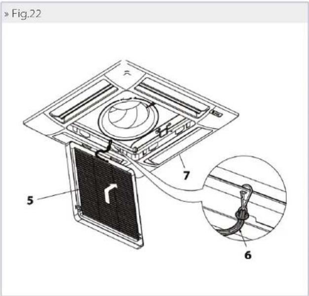
9.3 CLEANING THE AIR FILTER FCND02A GRILLE
Clean the air filter at least once a month and in any case at the start of the period of use (before the heating and the air conditioning season).
For fi Iter cleaning, proceed as follows (Fig.23):
- Before performing any work on the unit, disconnect it from the power supply.
- Remove the magnet covering panel (1) pull down.
- Remove one of the two safety cables (2) to have free access to the filter.
- Unscrew slightly the fixing screws (3) of support brackets (4).
- From position (A) fi g., move the two brackets (4) horizontally fi rst and then vertically along "L" guides, to move the screws (3) to position (B).
- Remove the air filter (5) pulling out it.
- Use a vacuum cleaner to remove dust. If dust is glued to the filter, remove it with clean or soapy water, rinse the filter with clean water and dry it.
- Put the grille (5) back in place the brackets (4) in position (A) of fig. 32 and tighten screws again (3).
It is recommended to replace the air fi Iter once a year, using an original replacement fi Iter; the indoor unit model can be found on the identification plate located on the tank inside the unit, behind the air fi Iter.
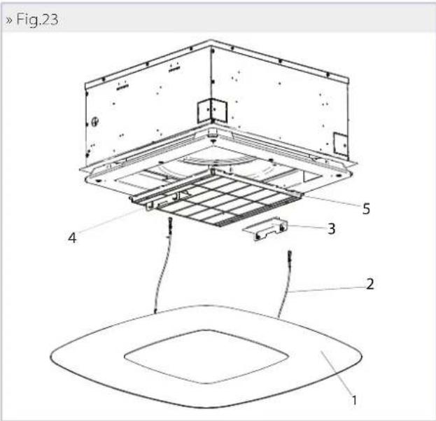
9.4 CLEANING OF FCND02A GRILL COVER PANEL
— Use a soft and dry cloth.
— Never pour liquids onto the unit, as this could cause electrical discharges and damage the internal components.
— Never use harsh chemical solvents.
WARNING: NEVER USE ABRASIVE TOOLS of any kind. Failure to follow this instruction may result in irreversible damage to the surface.
9.5 ELECTRIC CONTROL BOARD
Once a year, check that the electrical wires are properly tightened on their terminal blocks.
9.6 ADDITIONAL MAINTENANCE
Inspecting, cleaning, or replacing internal components requires the removal of the main condensate tank.
Tank removal (Fig.24 and Fig.25):
— Remove the air intake grille (for standard grille); Remove the DIBOND cover panel pull down it and separate from the unit (for FCND02A grille).
— Empty the condensate remaining in the tank into a bucket by means of a pump through the condensate drain opening of the auxiliary water drip tray (Fig.15 and Fig.16).
— Remove the front panel assembly (panel assembly) (1) by unscrewing the four fastening screws. Remove the support plates (2) of the tank (3) by removing the screws.
— Remove the tank, handling it with care.
— Clean the inside of the tank.
— Check that the heat exchanger is clean. If needed, use a vacuum cleaner with a rubber tip to remove dust being careful not to damage the fins.
Reinstallation of the tank:
— Put the tank (3) back in place with its supporting plates (2) and tighten the fastening screws.
— Put the front panel (1) back in place using the two tank plate clips to keep it suspended on the unit.
— Tighten the fastening screws.
— Put the grille back in place together with the air filter.
— Hook the grille's safety cable to the appropriate supports. — Close the grille and put back the retainers fastening screws (for standard grille), Put back tha cover panel in original position. (for FCND02A grille).
»Fig.24
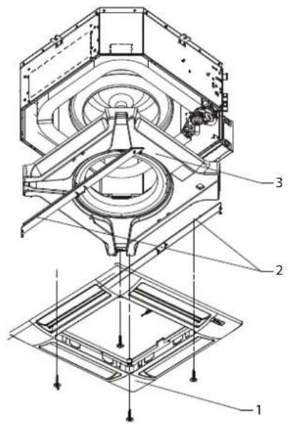
»Fig.25
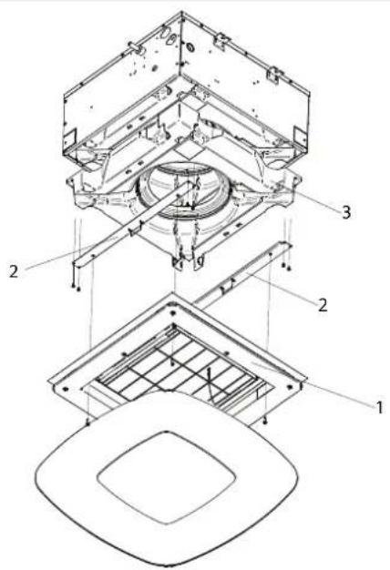
9.7 ABNORMAL WATER LEVEL
In case of abnormal backflow of water into the condensate tank (due to a faulty pump, a dirty tank, a plugged drain pipe, etc.), a safety contact (float switch) closes the control valves.
10 TROUBLESHOOTING
If the unit is not working properly, before calling a service engineer carry out the checks indicated in the table below.
If the problem cannot be solved, contact your dealer or the nearest service centre.
| PROBLEM CAUSE SOLUTION | ||
| The unit fails to work | No power supply Restore the power supply | |
| The automatic safety cutout has tripped Call a service centre for assistance | ||
| The on/off switch is on Start the unit by moving the switch to 1 | ||
| The unit provides insufficient cooling or heating | The air filter is dirty or clogged Clean the air filter | |
| The heat exchanger is dirty Call the installer for assistance | ||
| An obstacle is obstructing the air intake or outlet Remove the obstacle | ||
| Air is trapped inside the heat exchanger Call the installer for assistance | ||
| There are open windows and/or doors Close windows and/or doors | ||
| The minimum speed has been selected | Select medium or maximum speed | |
| The unit “leaks” water | The unit has not been installed with the correct inclination | Call the installer for assistance |
| The drainage outlet is clogged | Call the installer for assistance | |
| The pump is blocked | Call the installer for assistance | |
» Rated technical data FWH-A - 2 pipes
| FWH-A 02 03 04 | |||||||||||
| Speed min med max min med max min med max | |||||||||||
| Total cooling capacity (1)(E) kW | 1,70 1,97 2,53 2,39 3,55 4,31 3,40 4,61 5,00 | ||||||||||
| Sensible cooling capacity | (1)(E) KW | 1,33 1,60 2,14 1,66 2,53 3,18 2,43 3,44 3,79 | |||||||||
| FCEER class | (E) | C | C | D | |||||||
| Water flow | (1) | l/h | 295 | 342 | 441 | 416 | 616 | 749 | 593 | 803 | 873 |
| Water pressure drop | (1)(E) kPa | 3 | 4 | 6 | 9 | 19 | 26 | 9 | 16 | 18 | |
| Heating capacity | (2)(E) KW | 1,97 2,33 3,10 2,29 3,44 4,30 3,49 4,92 5,35 | |||||||||
| FCCOP class (E) | C | D | E | ||||||||
| Water flow | (2) | l/h | 342 | 404 | 539 | 399 | 597 | 747 | 607 | 855 | 930 |
| Water pressure drop | (2)(E) kPa | 3 | 5 | 8 | 7 | 15 | 22 | 8 | 15 | 17 | |
| Rated air flow | m^3/h | 297 | 379 | 557 | 306 | 487 | 640 | 479 | 717 | 805 | |
| Power input | (E) | W | 18 | 23 | 42 | 32 | 40 | 50 | 57 | 74 | 89 |
| Total sound power level | (3)(E) dB(A) | 33 | 37 | 45 | 40 | 44 | 50 | 47 | 55 | 58 | |
| Water content - standard coil | dm^3 | 1,14 | 1,63 | 1,63 | |||||||
| Cross-section area of power cables | (4) | mm^2 | 1,00 | 1,00 | 1,00 | ||||||
| Power supply cable type | NO7V-K | ||||||||||
| Safety fuse F | A | 2 | 2 | 2 | |||||||
| Fuses type | gG | ||||||||||
| FWH-A 06 07 08 | |||||||||||
| Speed min med max min med max min med max | |||||||||||
| Total cooling capacity (1)(E) kW | 4,645,367,015,166,118,246,348,619,73 | ||||||||||
| Sensible cooling capacity | (1)(E) kW | 3,423,995,293,684,376,104,596,407,35 | |||||||||
| FCEER class | (E) | C | |||||||||
| Water flow | (1) | l/h | 805 | 930122389310601434109714981696 | |||||||
| Water pressure drop | (1)(E) kPa | 14 | 18 | 28 | 12 | 16 | 26 | 16 | 26 | 32 | |
| Heating capacity | (2)(E) kW | 5,166,068,175,226,539,186,719,5311,1 | |||||||||
| FCCOP class (E) | D | C | D | ||||||||
| Water flow | (2) | l/h | 8971053142090811361596116716561930 | ||||||||
| Water pressure drop | (2)(E) kPa | 14 | 18 | 30 | 10 | 15 | 26 | 15 | 26 | 33 | |
| Rated air flow | m^3/h | 801 | 997 | 1494 | 718 | 902 | 1380 | 902 | 1380 | 1651 | |
| Power input | (E) | W | 47 | 64 | 108 | 47 | 64 | 108 | 64 | 108 | 147 |
| Total sound power level | (3)(E) dB(A) | 35 | 40 | 51 | 35 | 40 | 51 | 40 | 51 | 56 | |
| Water content - standard coil | dm^3 | 2,30 | 3,34 | 3,34 | |||||||
| Cross-section area of power cables | (4) | mm^2 | 1,00 | 1,00 | 1,00 | ||||||
| Power supply cable type | NOV-K | ||||||||||
| Safety fuse F | A | 2 | 2 | 2 | |||||||
| Fuses type | gG | ||||||||||
(1) Water temperature 7°C / 12°C, air temperature dry bulb 27°C, wet bulb 19°C (47% relative humidity) according to EN1397:2021
(2) Water temperature 45°C / 40°C, air temperature 20°C
(3) Sound power measured according to standards ISO 3741 and ISO 3742
(4) The shown section is to be considered as the minimum recommended section. The cables must be chosen in compliance with CE UNEL 35024/1 standard.
(E) EUROVENT certified data
Power supply 230-1-50 (V-ph-Hz)
» Rated technical data FWH-A - 4 pipes
| FWH-A 02 03 04 | |||||||||||
| min med | max min med | max min med max | |||||||||
| Speed | 1.231.231.23 | ||||||||||
| Total cooling capacity DF (1)(E) kW | 1,561,85 | 2,352,012,83 | 3,382,583,383,62 | ||||||||
| Sensible cooling capacity DF (1)(E) kW | 1,241,49 | 1,941,492,22 | 2,772,002,773,02 | ||||||||
| FCEER class DF (E) | CEE | ||||||||||
| Water flow DF 1R 1/h | 2713214 | 10351493589 | 453593637 | ||||||||
| Water pressure drop DF 1R (E) kPa | 3 | 4 | 6 | 10 | 16 | 22 | 5 | 8 | 9 | ||
| Heating capacity DF 1R | (2)(E) kW | 2,532,883,552,753,624,223,674,544,81 | |||||||||
| FCCOP class DF 1R | (E) | C | D | E | |||||||
| Water flow DF 1R | (2) | 1/h | 222258311241317369322398421 | ||||||||
| Water pressure drop DF 1R | (2)(E) kPa | 4586.9 | 12 | 589 | |||||||
| Rated air flow DF 1R | m^3/h | 289366583306487640 | 479717805 | ||||||||
| Power input DF 1R | (E) | W | 18 | 23 | 42 | 35 | 55 | 73 | 57 | 74 | 89 |
| Total sound power level DF 1R | (3)(E) | dB(A) | 33 | 37 | 45 | 40 | 44 | 50 | 47 | 55 | 58 |
| Water content - additional coil DF 1R | dm^3 | 0,49 | 0,49 | 0,49 | |||||||
| Cross-section area of power cables | (4) | mm^2 | 1,00 | 1,00 | 1,00 | ||||||
| Power supply cable type | N07V-K | ||||||||||
| Safety fuse F | A | 2 | 2.2 | ||||||||
| Fuses type | gG | ||||||||||
| FWH-A 06 08 | ||||||||
| min med | max min med | max | ||||||
| Speed | 123123 | |||||||
| Total cooling capacity DF (1)(E) kW | 4,736,607,455,838,489,00 | |||||||
| Sensible cooling capacity DF (1)(E) kW | 3,475,045,814,296,566,98 | |||||||
| FCEER class DF (E) | C | D | ||||||
| Water flow DF 1R 1/h | 82211481299101014771571 | |||||||
| Water pressure drop DF 1R (E) kPa | 10 | 20 | 25 | 16 | 31 | 34 | ||
| Heating capacity DF 1R | (2)(E) kW | 6,578,769,678,6411,712,4 | ||||||
| FCCOP class DF 1R | (E) | C | ||||||
| Water flow DF 1R | (2) | 1/h | 63484092975710261083 | |||||
| Water pressure drop DF 1R | (2)(E) kPa | 12 | 19 | 23 | 16 | 27 | 30 | |
| Rated air flow DF 1R | m2/h | 7181147 | 13809021544 | 1651 | ||||
| Power input DF 1R | (E) | W | 47 | 86 | 108 | 64 | 128 | 147 |
| Total sound power level DF 1R | (3)(E) | dB(A) | 39 | 47 | 51 | 40 | 54 | 56 |
| Water content - additional coil DF 1R | dm3 | 1,04 | 1,04 | |||||
| Cross-section area of power cables | (4) | mm2 | 1,00 | 1,00 | ||||
| Power supply cable type | N07V-K | |||||||
| Safety fuse F | A | 2 | 2 | |||||
| Fuses type | gG | |||||||
(1) Water temperature 7°C / 12°C, air temperature dry bulb 27°C, wet bulb 19°C (47% relative humidity) according to EN1397:2021
(2) Water temperature 65°C / 55°C, air temperature 20°C
(3) Sound power measured according to standards ISO 3741 and ISO 3742
(4) The shown section is to be considered as the minimum recommended section. The cables must be chosen in compliance with CFI - UREI 35024/1, standard.
(E) EUROVENT certified data
Power supply 230-1-50 (V-ph-Iz)
| Mod. | |
| kg | |
| FWHC2ATN/AFN | 23 + 2,5 |
| FWHC3/04ATN/AFN | 24 + 2,5 |
| FWHC6ATN/AFN | 42 + 5 |
| FWHC7/08ATN/AFN | 43+5 |
| FWH-A FWH-A 02-03-04 FWH-A 06-07-08 | |||
| CONDENSATE DRAINAGE PUMP | |||
| Power supply | V - ph - Hz 230 - 1-50 230 - 1-50 | ||
| Rated current | l/h 24.24 | ||
| Lifting height above the unit | mm 900 900 | ||
| Power input | kW 0,011 0,011 | ||
| INTAKE OF FRESH AIR TO BE TREA--- | |||
| Number of intakes | nr | 3 | |
| Connection dimensions | mm ∅ 100 | ||
| OUTLET OF AIR IN ADJACENT ROOMS | |||
| Number of intakes | nr 2 | 2 | |
| Connection dimensions | mm | ∅ 150 | ∅ 180 |
| INTRODUCTION OF FRESH AIR DIRECTLY INTO THE ROOM | |||
| Number of intakes | nr 2 | 2 | |
| Connection dimensions | mm | ∅ 150 | ∅ 180 |
12 ELECTRICAL WIRING DIAGRAM LEGEND
Make the electrical connections with the power supply disconnected, in accordance with current safety regulations. Check that the mains electricity supply is compatible with the voltage shown on the unit rating plate.
The electrical connections indicated must be made by the installer
— IL: Circuit breaker (not supplied)
— F: Safety 2A fuse (not supplied)
— CN: Fast on/screw terminal board
— MV: Fan motor
— C1: Condenser for fan motor
— AT: Autotransformer for fan motor
— MP: Condensate drainage pump
— FLOAT SWITCH: Float
— BN: Brown = pump power supply phase
— BK: Black = float switch alarm signal
— BU: Blue = pump power supply neutral
— GY: Grey = common float alarm
— VC ON/OFF: ON/OFF cold/hot water valve (2 pipes system) (accessory)
— ON/OFF cold water valve (4 pipes system)
— VH ON/OFF: hot water valve (4 pipes system) (accessory)
— BN: Brown = valves power supply phase
— BU: Blue = neutral valve power supply
— SAI: Pre-installed internal air temperature probe
— SAE: Remote air temperature probe (accessory)
— SW: Water temperature sensor (accessory)
— SWH: Hot water temperature probe additional coil (4-pipe units). Available in option only with SW.
— SUI: Pre-installed internal air relative humidity probe
— SUE: Remote air relative humidity probe (accessory)
12.1 SPECIFIC FOR WIRING DIAGRAMS WITH FWECSA CONTROL
— T1: Transformer 230Vac/24Vac (not supplied)
— VC 0-10: modulating cold/hot water 2 pipes system (accessory); modulating cold water valve 4 pipes system (accessory)
— VH 0-10: Hot water valve modulating 0/10V 4 pipes system (accessory)
— RD: Red = +24V valves power supply
— BK: Black = 0V valve power supply / control signal GND
— grey: Grey = 0-10 Vdc valve control signal for modulating
1 AVANT DE COMMENCER L'INSTALLATION .... p. 49
2 UTILISATION PREVUE p.49
LIEU D'INSTALLATION p. 49
LIMITES DE FONCTIONNEMENT ...... p. 50
3 DESCRIPTION DE L'UNITÉ p. 50
3.1 VERSIONS DISPONIBLES p. 50
4 DONNÉES DIMENSIONNELLES.... p. 52
5 INSTALLATION p. 52
5.1 AVERTISSEMENTS POUR L'INSTALLATION.... p. 52
natural_image
Close-up of a white and black ceiling-mounted air conditioner unit with a mesh grille (no text or symbols visible)3.5ACCESSOIRES
natural_image
Technical line drawing of a mechanical assembly with no visible text or symbols1 Port sonde eau
natural_image
Technical line drawing of a curved mechanical component with labeled parts (no readable text or symbols)1 Chevalet fixation sonde
Raccordements hydrauliques
| Unité | Raccordement échangeur | |
| FWH02ATN,FWH03ATN, FWH04ATN (2 tubes) | 1/2" gas F | |
| FWH06ATN,FWH07ATN, FWH08ATN (2 tubes) | 3/4" gas F | |
| Rafraîchissement | Chauffage | |
| FWH02AFN,FWH03AFN, FWH04AFN (4 tubes) | 1/2" gas F | 1/2" gas F |
| FWH06AFN,FWH08AFN (4 tubes) | 3/4" gas F | 1/2" gas F |
natural_image
Simple line drawing of two crossed metal tools (no text or symbols)natural_image
Technical line drawing of a mechanical assembly with no visible text or symbols»Fig.3
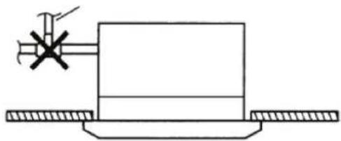
natural_image
Pure mechanical diagram showing a lever and base with no text or symbols5.2 MONTAGE UNITÉS À L'AIDE DES SCHÉMAS DIMENSIONNELS
natural_image
Technical line drawing of a hexagonal mechanical housing or enclosure with mounting holes and internal compartments (no text or symbols)» Fig.9 FWH 02-03-04

»Fig.6

»Fig.10

Montage panneau frontal/grille FPAN
Montage panneau frontal/grille FCND02A
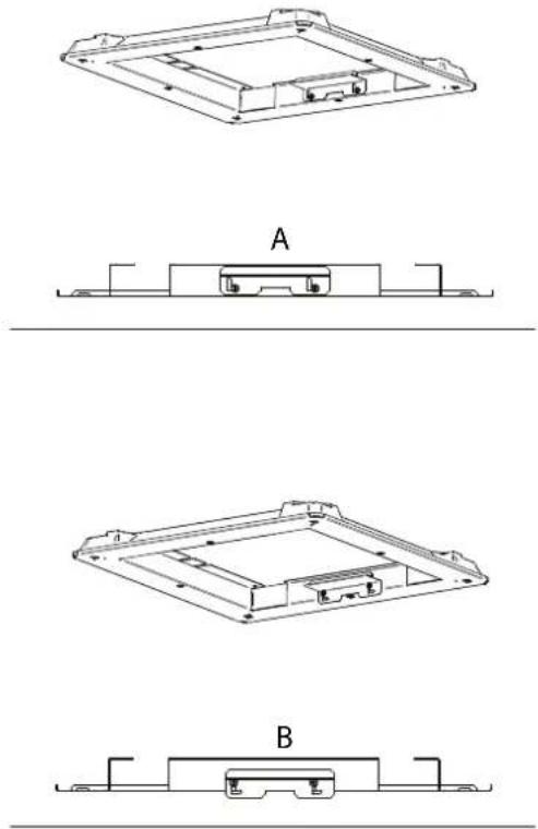
natural_image
Technical line drawings of a mechanical component with three views (A, B, and C) showing internal structures without any text or symbols.6 VÉRIFICATION FONCTIONNELLE
6.1 CONTRÔLES PRÉALABLES
S'assurer :
| Unité | Type vanne | Raccord | Δp min [kPa] | ||
| FWH02ATN,FWH03ATN,FWH04ATN (2 tubes) | 2 voles | 3/4" M | 32 | ||
| FWH06ATN,FWH07ATN,FWH08ATN (2 tubes) | 2 voles | 1 1/4" M | 20 | ||
| Rafraîchissement | Chauffage | ||||
| Unité | Type vanne | Raccord | Δp min [kPa] | Raccord | Δp min [kPa] |
| FWH02AFN,FWH03AFN,FWH04AFN (4 tubes) | 2 voles | 3/4" M | 16 | 3/4" M | 16 |
| FWH06AFN,FWH08AFN (4 tubes) | 2 voles | 1 1/4" M | 20 | 17" M | 16 |
» Fig.18 FWH-A 06-07-08
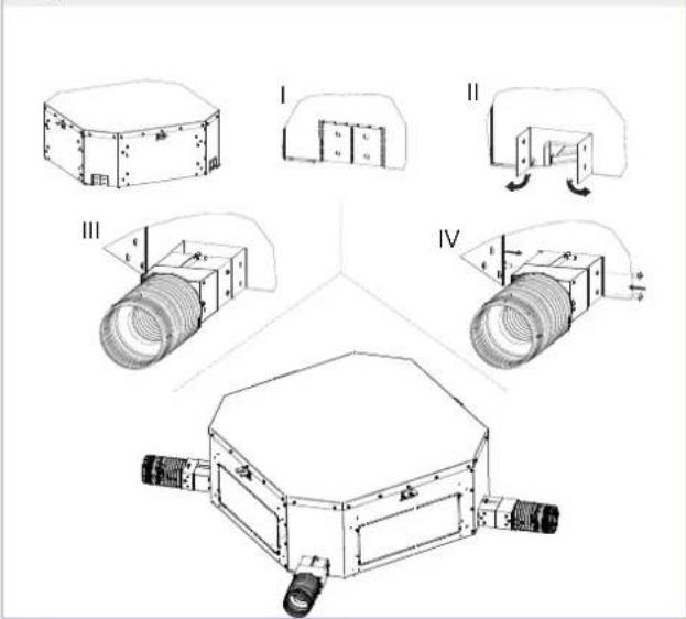
8.5 RACCORDEMENT DE REFOULEMENT D'AIR DANS DES PIÈCES ATTENANTES
natural_image
Technical line drawing of a mechanical housing or enclosure with mounting brackets and a central panel (no text or symbols)||
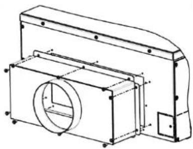
natural_image
Technical line drawing of a mechanical housing or enclosure with internal components and mounting holes (no text or symbols)III
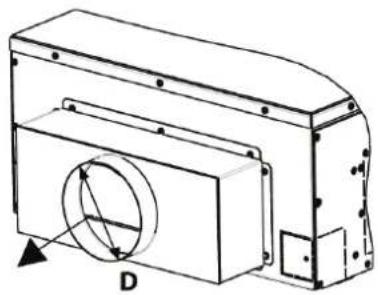
natural_image
Technical line drawing of a mechanical housing or enclosure with a circular component and labeled dimension D (no text or symbols beyond label)9ENTRETIEN
9.2 NETTOYAGE GRILLE D'ASPIRATION
» Fig.23
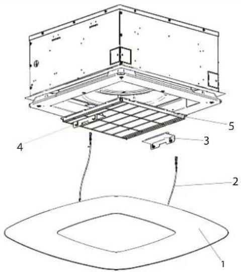
9.4 NETTOYAGE DU LE PANNEU DU FILTRE À AIR GRILLE FCND02A
»Fig.25
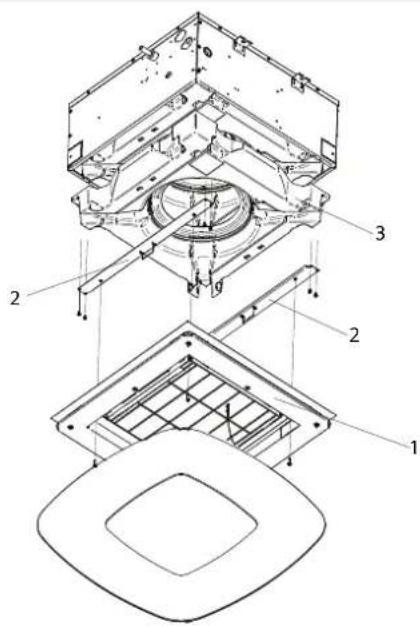
9.7 NIVEAU D'EAU ANORMAL
— BN: Marron = phase alimentation vannes
— BU: Bleu = neutre alimentation vannes
natural_image
Close-up of a white and black ceiling-mounted air conditioner unit with a mesh grille (no text or symbols visible)3.3ZUBEHÖR
natural_image
Technical line drawing of a mechanical assembly with no visible text or symbols1 Fühlerhalterung
natural_image
Line drawing of a pair of metal tools (no text or symbols)natural_image
Technical line drawing of a mechanical assembly with no visible text or symbols» Abb.3
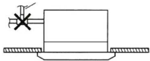
natural_image
Pure mechanical diagram showing a lever and base with no text or symbolsnatural_image
Technical line drawing of a hexagonal mechanical housing or enclosure with mounting holes and internal compartments (no text or symbols)» Abb.9 FWH 02-03-04

» Abb.6

» Abb.10

Montage des Frontpaneels/des Gitters FPAN
Anbringen des Frontpaneels: (Abb.12)
Montage de Frontpaneel/de FCND02A Gitter

natural_image
Technical line drawings of a mechanical component with three views (A, B, and C) showing internal structures without any text or symbols.6 FUNKTIONSPRÜFUNG
6.1 VORABKONTROLLEN
Sich vergewissern:
» Fig.18 FWH-A 06-07-08
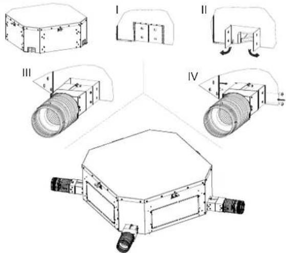
natural_image
Technical line drawing of a rectangular electronic device with mounting holes and a central panel (no text or symbols)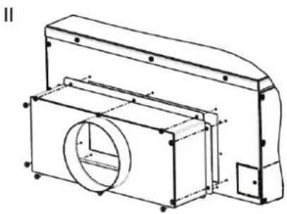
natural_image
Technical line drawing of a mechanical housing or enclosure with internal components and mounting holes (no text or symbols)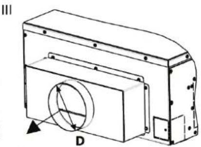
natural_image
Technical line drawing of a mechanical component with a circular cutout and labeled point D (no text or symbols beyond label)9WARTUNG
9.2 REINIGUNG DES ANSAUGGITTERS
» Abb.23
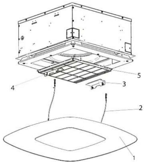
9.3 REINIGUNG DES LUFTFILTERS FCND02A GITTER
Control dedicado (FWEC2T/4T - FWECSA - FWEC1A-2A-3A ..... p. 93
Conexiones hidráulicas p. 93
natural_image
Close-up of a white and black ceiling-mounted speaker or vent with a textured grille (no text or symbols visible)3.3 ACCESORIOS
natural_image
Technical line drawing of a mechanical assembly with no visible text or symbols1 Portasonda de agua
Control dedicado (FWEC2T/4T - FWECSA - FWEC1A-2A-3A)
natural_image
Line drawing of two metal tools with handles and a central hub (no text or symbols)natural_image
Technical line drawing of a mechanical assembly with no visible text or symbols»Fig.3

natural_image
Simple line drawing of a mechanical assembly with a central block and two side supports (no text or symbols)5.2 MONTAJE DE LA UNIDAD
natural_image
Technical line drawing of a hexagonal mechanical housing or enclosure with mounting holes and internal compartments (no text or symbols)» Fig.9 FWH 02-03-04

»Fig.6

»Fig.10

Para instalar el frente: (Fig.12)
natural_image
Technical line drawing of a mechanical component with labeled parts (no text or symbols present)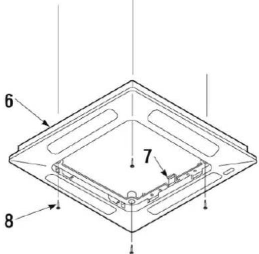
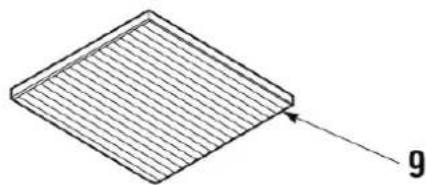
natural_image
Isometric view of a diamond-shaped grid structure with an arrow pointing to a labeled point 'g' (no text or symbols beyond the label)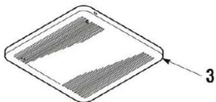
natural_image
Simple line drawing of a diamond-shaped object with two horizontal bars and an arrow pointing to the number 3 (no text or symbols on the object itself)natural_image
Technical line drawings of a mechanical component with three views (A, B, and C) showing different mounting or assembly configurations (no text or symbols present)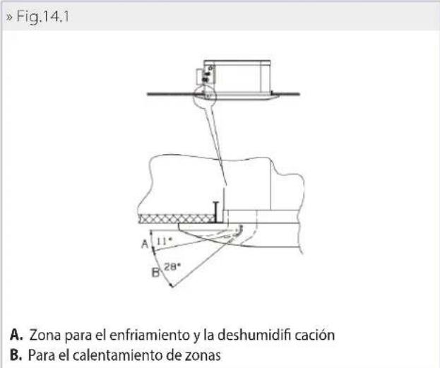
» Fig.18 FWH-A 06-07-08
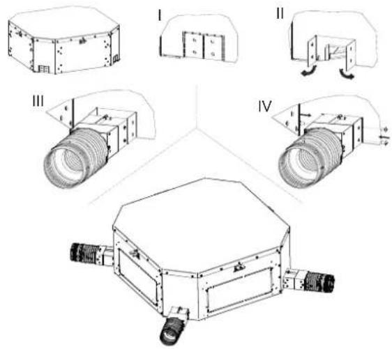
natural_image
Technical line drawing of a mechanical housing or enclosure with mounting holes and internal components (no text or symbols)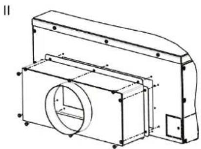
natural_image
Technical line drawing of a mechanical housing or enclosure with internal components and mounting holes (no text or symbols)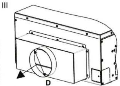
natural_image
Technical line drawing of a mechanical component with a circular feature and labeled point D (no text or symbols beyond label)9MANTENIMIENTO
9.3 LIMPIEZA DEL FILTRO DE AIRE REJILLA FCND02A
9.4 LIMPIEZA DEL PANEL DE CIERRE DE LA REJILLA FCND02A

9.7 NIVEL ANÓMALO DE AGUA
POUŽÍVEJTE VHODNÉ OSOBNÍ OCHRANNÉ POMŮCKY (RUKAVICE, OCHRANNÉ BRÝLE)

natural_image
Close-up of a white ventilation grille with uniform grating pattern (no text or symbols visible)natural_image
Close-up of a white and black ceiling-mounted air conditioner unit with a mesh grille (no text or symbols visible)3.3PŘÍSLUŠENSTVÍ
natural_image
Technical line drawing of a mechanical assembly with no visible text or symbols1 Držák vodní sondy
1 Spona pro sondu
natural_image
Line drawing of two metal clamps (no text or symbols)natural_image
Technical line drawing of a mechanical assembly with no visible text or symbols»Obr.3

natural_image
Pure mechanical diagram showing a lever and base with no text or symbols5.2 MONTÁŽ ROZMĚROVÝCH JEDNOTEK
natural_image
Technical line drawing of a hexagonal mechanical housing or enclosure with mounting holes and internal compartments (no text or symbols)»Obr.9
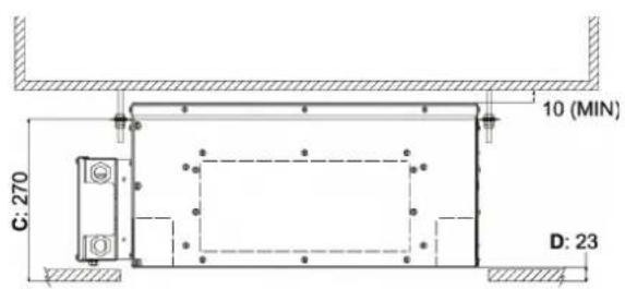
»Obr.6
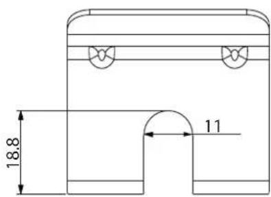
»Obr.10

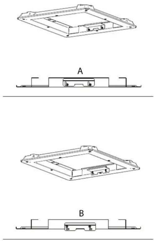
6 FUNKČNÍ KONTROLA
6.1 PŘEDBĚŽNÉ KONTROLY
Ujistěte se:
» Obr. 18 FWH-A 06-07-08
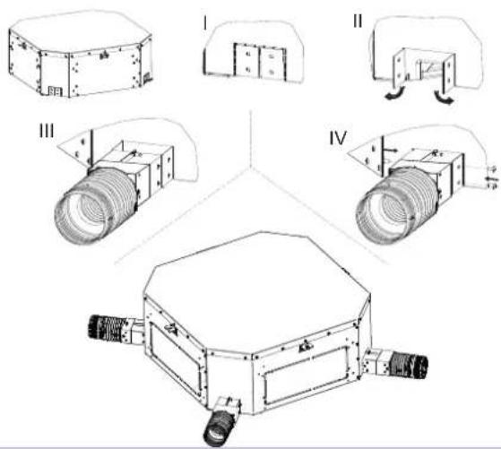
8.5 PŘIPOJENÍ PŘÍVODU VZDUCHU V SOUSEDNÍCH MÍSTNOSTECH
natural_image
Technical line drawing of a rectangular electronic device with mounting holes and a central screen (no text or symbols)||

natural_image
Technical line drawing of a mechanical housing or enclosure with internal components and mounting holes (no text or symbols)III

natural_image
Technical line drawing of a mechanical housing or enclosure with a circular component and labeled dimension D (no text or symbols beyond label)9ÚDRŽBA
9.3ČIŠTĚNÍMŘÍŽKYVZDUCHOVÉHO FILTRU FCND02A
9.4 ČIŠTĚNÍ UZAVÍRACÍHO PANELU MŘÍŽKY FCND02A
» Obr. 25
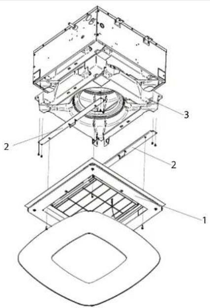
9.7 ABNORMÁLNÍ HLADINA VODY
natural_image
Close-up of a white ventilation grille with uniform grating pattern (no text or symbols visible)Rešetka: dizajnerska rešetka s Coandă efektom FCND02A
natural_image
Close-up of a white and black ceiling-mounted speaker or vent with a textured grille (no text or symbols visible)3.3 OPREMA
Elektroničke mikroprocesorske upravljačke ploče sa zaslonom
natural_image
Technical line drawing of a mechanical assembly with no visible text or symbols1 Nosač sonde za vodu
— Ako se koristi komplet ventila koji nije predložen, potrebno je ugraditi sondu na ULAZNU cijev, koristeći odgovarajući bakreni nastavak napunjen vodljivom pastom.
— Konačno, morate pravilno izolirati sondu kako biste bili sigurni da ispravno očitava temperaturu vode.
1 Držač sonde
Namjenska naredba (FWEC2T/4T - FWECSA - FWEC1-2-3)
natural_image
Simple line drawing of two crossed metal tools (no text or symbols)— Pažljivo izolirajte dovodne i odvodne cijevi vode kao i uređaje ugrađene na mreži (zaporni ventili, ...). Koristite materijal koji odgovara uvjetima uporabe i temperaturi vode.
natural_image
Technical line drawing of a mechanical assembly with no visible text or symbols»Fig.3
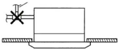
natural_image
Pure mechanical diagram showing a lever and base with no text or symbols5.2 MONTAŽA DIMENZIJSKIH JEDINICA
natural_image
Technical line drawing of a hexagonal mechanical housing or enclosure with mounting holes and internal compartments (no text or symbols)»Fig.9

»Fig.6

»Fig.10

Za postavljanje prednje strane: (Fig. 12)
— Okrenite dvije kopče za zaključavanje (5) prema dolje.
— Zakačite okvir ploče (6) za jedinicu pomoću dvije kuke (7) tako da ih spojite sa stezaljkama za zaključavanje (5).
— Provjerite točan položaj okvira panela u odnosu na spušteni strop. Ako je potrebno, prilagodite položaj unutarnje jedinice.
— Pričvrstite okvir ploče na jedinicu koristeći posebne isporučene vijke i podloške (8).
— Postavite rešetku (3) na mjesto, provjerite je li filtar (9) ispravno postavljen.
— Zakačite sigurnosni kabel za ploču, zatvorite rešetku i vratite pričvrsne vijke graničnika (2).
»Fig.12
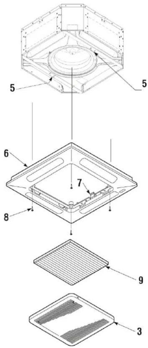
Montaža prednje strane/rešetke FCND02A
Prednja strana/rešetka, dostupna u verzijama FWH 02-03-04, isporučuje se u zasebnom paketu:

natural_image
Technical line drawing of a rectangular electronic component with mounting holes and internal structure (no text or symbols)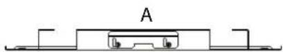

natural_image
Technical line drawing of a rectangular electronic component with mounting holes and internal structure (no text or symbols)
» Fig.18 FWH-A 06-07-08
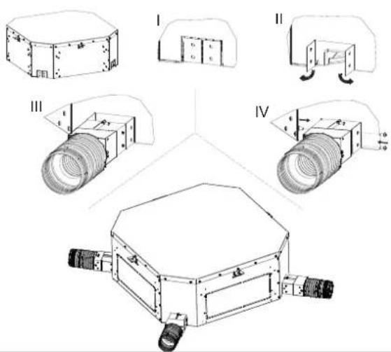
8.5 PRIKLJUČAK ZA DOVOD ZRAKA U SUSJEDNE PROSTORIJE
natural_image
Technical line drawing of a mechanical housing or enclosure with mounting holes and internal components (no text or symbols)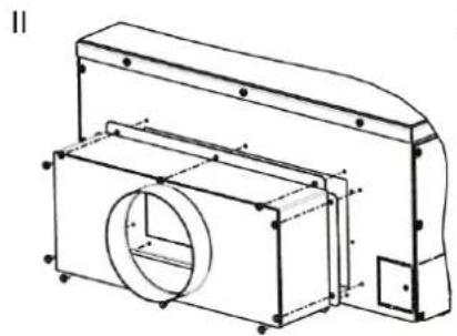
natural_image
Technical line drawing of a mechanical assembly with a circular component and housing (no text or symbols)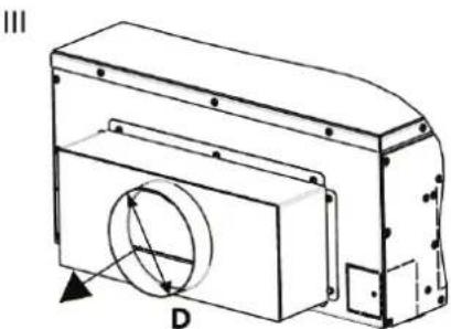
natural_image
Technical line drawing of a mechanical component with a circular cutout and labeled dimension D (no text or symbols beyond labels)9ODRŽAVANJE
9.2 ČIŠĆENJE FPAN USISNE REŠETKE
9.4 ČIŠĆENJE PLOČE ZA ZATVARANJE REŠETKE FCND02A
— Koristite meku, suhu krpu.
— Nikada nemojte sipati tekućinu na uređaj jer to može uzrokovati strujni udar i oštetiti unutarnje dijelove.
— Nikada ne koristite agresivna kemijska otapala.
UPOZORENJE: APSOLUTNO JE ZABRANJENO KORISTITI ABRA-ZIVNE ALATE bilo koje vrste. Inače riskirate nepovratno ugroziti površinu.
9.5 ELEKTRIČNI ORMAR
Jednom godišnje provjerite ispravnost brtvljenja električnih žica na njihovim priključnim stezaljkama.
9.6 DODATNO ODRŽAVANJE
Pregled, čišćenje ili zamjena unutarnjih komponenti zahtijevaju rastavljanje glavnog spremnika kondenzata.
Uklanjanje spremnika (Fig. 24 i Fig. 25):
— Uklonite usisnu rešetku (za FPAN rešetku); Uklonite DIBOND ploču za zatvaranje povlačenjem prema dolje, odvajajući je od jedinice (za rešetku FCND02A).
— Ispraznite kondenziranu vodu preostalu u spremniku u kantu pomoću crpke kroz otvor za odvod kondenzata u pomoćnoj posudi (Fig. 15 i Fig. 16).
— Uklonite prednji sklop (tijelo ploče) (1) tako da odvrnete četiri pričvrsna vijka. Uklonite potporne ploče spremnika (2) (3) uklanjanjem vijaka.
— Uklonite spremnik pažljivo rukujući njime.
— Očistite unutrašnjost spremnika.
— Provjerite je li izmjenjivač topline čist. Po potrebi obrišite pra šinu usisavačem s gumenom mlaznicom, pazeći da ne oštetite peraje.
Ponovno sastavljanje spremnika:
— Vratite spremnik (3) na mjesto s odgovarajućim potpornim pločama (2) i zategnite pričvrsne vijke.
— Vratite prednju ploču (1) na mjesto pomoću dvije kopče na plo čama spremnika kako biste je objesili o uređaj.
— Ponovno zategnite pričvrsne vijke.
— Vratite rešetku s filtrom zraka na mjesto.
— Zakačite sigurnosno uže za rešetku na odgovarajuće nosače.
— Zatvorite rešetku i zamijenite pričvrsne vijke graničnika (za rešetku FPAN). Vratite ploču za zatvaranje u prvobitni položaj. (za rešetku FCND02A).
»Fig.24
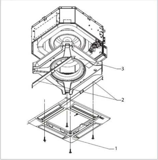
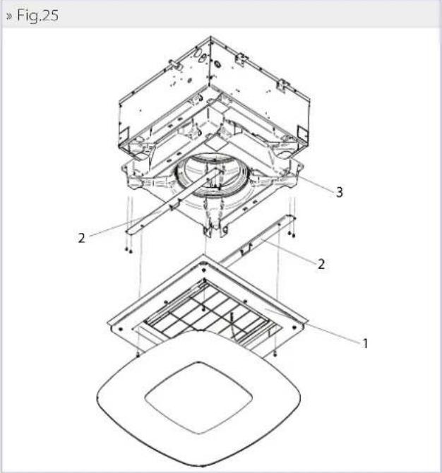
9.7 NEDOZVOLJENA RAZINA VODE
U slučaju nenormalnog porasta vode u spremniku kondenzata (zbog neispravne crpke, prljavog spremnika, začepljene odvodne cijevi,...), sigurnosni kontakt (plovak) zatvara regulacijske ventile.
10 RJEŠAVANJE KVAROVA
natural_image
Close-up of a white ventilation grille with uniform grating pattern (no text or symbols visible)natural_image
Close-up of a white and black ceiling-mounted air conditioner unit with a mesh grille (no text or symbols visible)3.3 ACCESORII
Panouri de comandă electronice cu microprocesor cu afi șaj
natural_image
Technical line drawing of a mechanical assembly with no visible text or symbolsnatural_image
Line drawing of two crossed metal tools (no text or symbols)natural_image
Technical line drawing of a mechanical assembly with no visible text or symbols»Fig.3

natural_image
Pure mechanical diagram showing a lever and base plate without any text, numbers, or symbols5.2 MONTAREA UNITĂȚILOR DIMENSIONALE
natural_image
Technical line drawing of a hexagonal mechanical housing or enclosure with mounting holes and internal compartments (no text or symbols)»Fig.9

»Fig.6

»Fig.10
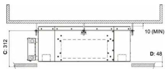
Pentru a instala panoul frontal: (Fig. 12)
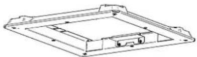
natural_image
Technical line drawing of a rectangular electronic component with mounting holes and internal structure (no text or symbols)
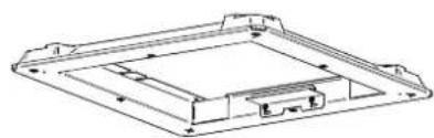
natural_image
Technical line drawing of a rectangular electronic component with mounting holes and internal structure (no text or symbols)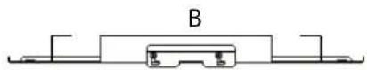
6 VERIFICARE FUNCTIONALĂ
6.1 CONTROALE PRELIMINARE
Asigurati-vă că:
» Fig.18 FWH-A 06-07-08

8.5 RACORDUL DE ALIMENTARE CU AER ÎN ÎNCĂPERI ADIACENTE
natural_image
Technical line drawing of a mechanical housing or enclosure with mounting holes and internal components (no text or symbols)||
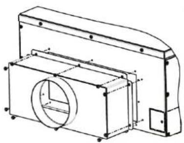
natural_image
Technical line drawing of a mechanical housing or enclosure with internal components and mounting holes (no text or symbols)III
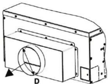
natural_image
Technical line drawing of a mechanical housing or enclosure with a circular component and labeled dimension D (no text or symbols beyond label)9ÎNTRETINERE
9.2 CURĂȚAREA GRILEI DE ADMISIE FPAN
9.3 CURĂȚAREA FILTRULUI DE AER AL GRILEI FCND02A
9.4 CURĂTAREA CAPACULUI GRILEI FCND02A
»Fig.25
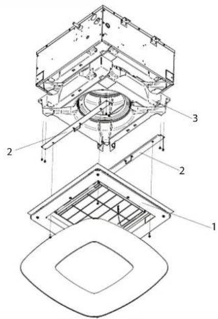
9.7 NIVEL ANORMAL AL APEI
(E) Date certificate EUROVENT
1)
Clip di bloccaggio / Locking clips / Clips de blocage / Linspanndips / Clip de bloqueo / Zajišťovaci klip / Kvačica za zaključavanje / Clerne de blocare
2)
Tiranti / Tie rods / Tirants / Spannyorrichtungen / Tirantes / Tåhla / Šipke / Bare de leqaturä
3)
Vasca per la raccolta della condensa / Condensate drip tray / Bac de collecte des condensats / Kondenswassersammelbecken / Depósito para el líquido de condensación / Sběrná nádoba na kondenzár / Spremnik za skupljanje kondenzata / Rezervor de colectare a condensului
4)
Pompa per lo scarico della condensa / Condensate drainage pump / Pompe d'évacuation des condensats / Kondenswasserablasspumpe / Bomba de descarga de condensado / Čerpadlo pro odvod kondenzálu / Crpka za odvod kondenzala / Pompa de evacuare a condensului
5)
Scambiatore di calore / Heat exchanger / Échangeur de chaleur / Kältem tttel / Intercambiador de calor / Výměnik tepla / Izmjenjivač top line / Schimbátor de cálduřa
6)
Ventilatore / Fan / Ventilateur / Lüfter / Ventilador / Ventilator / Ventilator
7)
Motore / Motor / Moteur / Motor / Motor / Ventilator / Motor / Motor / Motor
8)
Coisentazione interna / Internal insulation / Isolation interne / Wärmecämmung innen / Aislamiento interno / Unutamja Izolacija / Izolatie interioară
9)
1) Clip di bloccaggio / Locking clips / Clips de blocage / Einspannclips / Clip de bloqueo / Zajišťovaci klp / Kvačica za zaključavanje / Cleme de blocare
2) Tiranti / Tie rods / Tirantis / Spannvorrichtungen / Tirames / Tâhla / Špike / Bare de legătură
3) Vasa per la raccolta della condensa / Condensare drip tray / Bac de colecte des condensats / Kondenswassersammelbecken / Depósito para el líquido de condensación / Shēmā nádoba na kondenzát / Spremnik za skupljanje kondenzata / Rezervor de colectare a condensului
4) Pompa per lo scarico della condensa / Condensate drainage pump / Pompe d'évacuation des condensats / Kondenswasserablasspumae / Bomba de descarga de condensado / Čerpadlo pro odvod kondenzátu / Crplka za odvod kondenzata / Pompa de evacuare a condensului
5) Scrambiatore di calore / Heat exchanger / Échangeur de chaleur / Käfermittel / Intercambiador de calor / Výměník lepla / Lvmjenjivač topline / Schimbátor de căldură
6) Gruppo motoventilante / Fan drive assembly / Groupe moto-ventilateur / Lüftungsmotereinheit / Grupo motoventilador / Jednotka motorového ventilatoru / Jednotka motora ventilatora / Unitate motor-ventilator
7) Colibentazione Interna / Internal insulation / Isolation Interne / Wärmedämmung Innen / Aislamiento interno / Vnitchí izolace / Unutamja izolacija / Izolatie interioară
8) Larniera latrale / Lateral sheet metal / Tôle latérale / Seitenoblech / Chapa lateral / Boční plech / Boční lim / Tablă laterală
9) Posteriore in lamiera / Sheet metal back / Pannicau posterieur en tõle / Rückseite aus Bloch / Posterior de chapa / Cadni plechová čast / Stražnja strana lima / Portea din spate din tablă
10) Staffe ci rinforzo / Reinforcement brackets / Brides de renfort / Verstärkungsbügel / Estilbos de refuerzo / Výztužné sloucky / Nosači za pojačanje / Suporturi de Intānre
11 Staffe per il supporto dello scambiatore / Exchanger support brackets / Bride de soutien de l'échangeur / Haltebrügel des Wärmetauschers / Estribos de apoyo del intercambiador / Držaky pro podepteni vyméniku / Nosači za podupiranje izmjenjivača / Suporturi pentru suportul schimbătorului de căldură
12) Scalola elektrica / Electric box / Boîtier électrique / Verteilungskasten / Caja conexiones eléctricas / Elektrická skřín / Elektrína kulija / Cutia electricá
» Dimensionale FWH-A 02-03-04 2 tubi / Dimensional drawing FWH-A 02-03-04, 2 pipes / Schéma dimensionnel FWH-A 02-03-04 2 tuyaux / Abmessungszeichnung FWH-A 02-03-04 2 Rohre / Dibujo dimensional FWH-A 02-03-04 2 tubos / Rozměrový nákres FWH-A 02-03-04 2 trubky / Dimenzionalno FWH-A 02-03-04 s 2 cíjevi / Schită dimensională FWH-A 02-03-04 2 tevi
» 13.3

LEGENDA / LEGEND / LÉGENDE / LEGENDE / LEYENDA / VYSVĚTLIVKY / POJAŠNJENJE / LEGENDA 1)
Scato a eletrica / Electric box / Boîtier électrique / Verteilungskasten / Caja conexiones electricas / Elektrická skiîn / Flektična kutija / Cutia electrică
2)
Scarico condensa a 10 / Condensate discharge a 10 / Purge des condensats, a 10 / Kondenswasserablass, a 10 / Descarga condensados, a 10 / Ocvod kondenzálu a 10 / Ocvod kondenzala a 10 / Fvarcúrea condensului e 10
3)
Jusica acqua o 1/2" gas feminina / Water outlet o 1/2" female gas / Sortie d'eau o 1/2" gaz femme / Wasserauslauf o 1/2" Innengewinde gas / Salida agua o 1/2" hembra gas / Výstup vody o 1/2" plynová zásuvka / Iziaz vode o 1/2" za plin, ženski / lejire de apá o 1/2" gaz mamá
4)
Entrata agua a 1/2" gas femmina / Water inlet a 1/2" female gas / Entrée d'eau a 1/2" gaz femme / Wassereinauf a 1/2" Innengewinde gas / Entrada agua a 1/2" hembra gas / Vstup vody a 1/2" plynová zásuvka / Ulaz vode a 1/2" za plin, ženski / Intrare de apá a 1/2" gaz mama/
» Dimensionale FWH-A 06-07-08 2 tubi / Dimensional drawing FWH-A 06-07-08, 2 pipes / Schéma dimensionnel FWH-A 06-07-08 2 tuyaux / Abmessungszeichnung FWH-A 06-07-08 2 Rohre / Dibujo dimensional FWH-A 06-07-08 2 tubos / Rozměrový nákres FWH-A 06-07-08 2 trubky / Dimenzionalno FWH-A 06-07-08 s 2 cijevi / Schită dimensională FWH-A 06-07-08 2 tevi
» 13.4
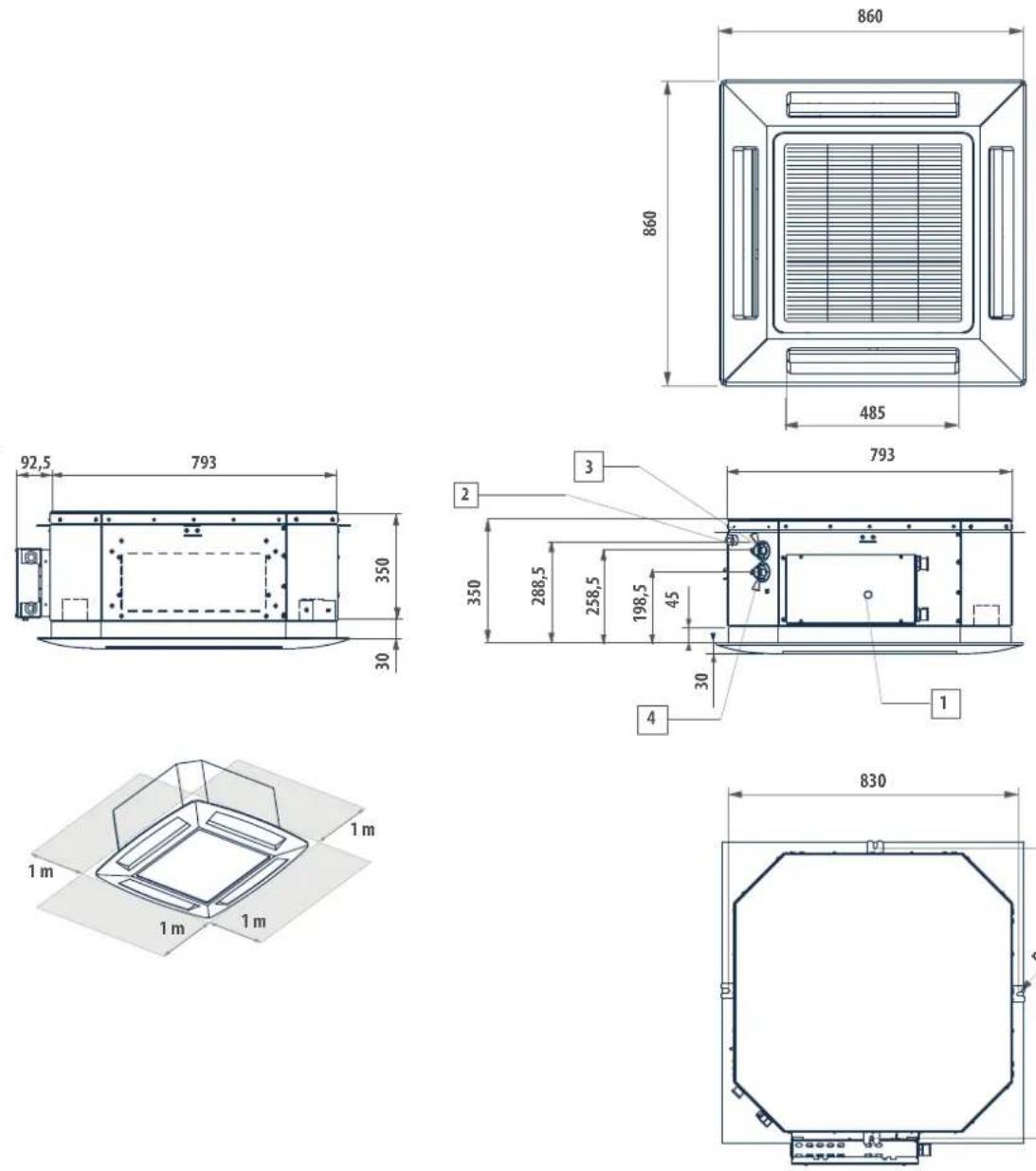
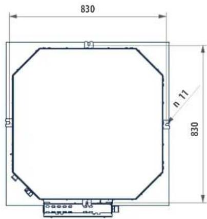
LEGENDA / LEGEND / LÉGENDE / LEGENDE / LEYENDA / VYSVĚTLIVKY / POJAŠNJENJE / LEGENDA
1)
Scatola elettrica / Electric box / Boîtier électrique / Verteilungskasten / Caja conexiones électricas / Elektrická skíň / Elektična kutja / Cut a electrica
2)
Scarico condensa a 10 / Condensate discharge a 10 / Purge des condensals a 10 / Kondenswasserablass a 10 / Descarga condensados a 10 / Odvod kondenzalu a 10 / Odvod kondenzata a 10 / Evacuarea condensului a 10
3)
Uscita acqua o 3/4" gas femmina / Water outlet o 3/4" female gas / Sortie d'eau o 3/4" gaz femme / Wasserauslauf o 3/4" Innengewinde gas / Salida agua o 3/4" hembra gas / Výstup vody o 3/4" plynova zásuvka / Izlaz vode o 3/4" za plin, Ženski / Išire de apă o 3/4" gaz mamá
4)
Entrata acqua o 3/4" gas femmina /'Water inlet o 3/4" female gas / Entrée d'eau o 3/4" gaz femme /'Wassereinlauf o 3/4" Innergewinde gas / Entrada agua o 3/4" hembra gas /'Vstup vody o 3/4" plynová zásurka / Ulaz vode o 3/4" za plin, ženski / Intrare de apě o 3/4" gaz mamá
» Dimensionale FWH-A 02-03-04 4 tubi / Dimensional drawing FWH-A 02-03-04, 4 pipes / Schéma dimensionnel FWH-A 02-03-04 4 tuyaux / Abmessungszeichnung FWH-A 02-03-04 4 Rohre / Dibujo dimensional FWH-A 02-03-04 4 tubos / Rozměrový nákres FWH-A 02-03-04 4 trubky / Dimenzionalno FWH-A 02-03-04 s 4 cíjevi / Schiţă dimensională FWH-A 02-03-04 4 tevi
» 13.5
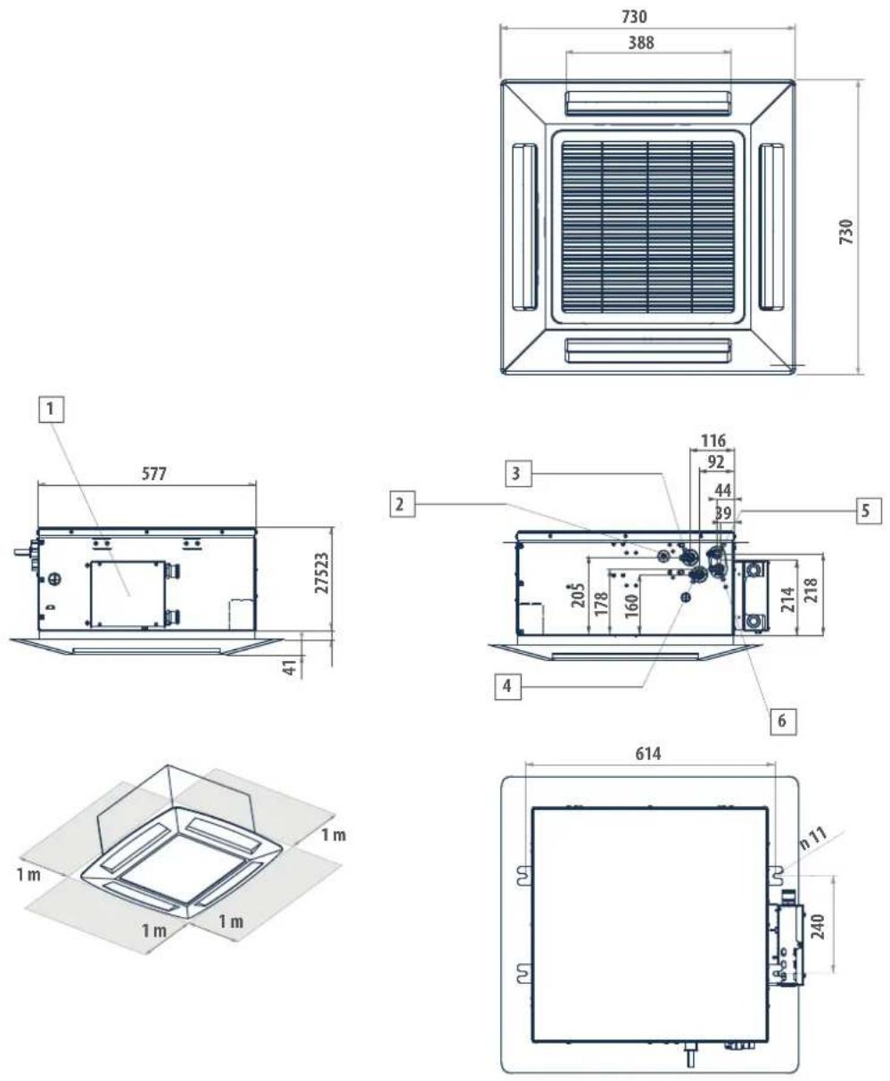
LEGENDA / LEGEND / LÉGENDE / LEGENDE / LEYENDA / VYSVĚTLIVKY / POJAŠNJENJE / LEGENDA
1)
Scato a elettrica / Electric box / Boitier electrique / Verteilungskasten / Gaja conexiones eléctricas / Elektrická skriň / Elektricna kutija / Cutia electrica
2)
Scarico condensa a 10 / Condensate discharge a 10 / Purge des condensats a 10 / Kondenswasserablass a 10 / Descarga condensados a 10 / Ocvod kondenzátu a 10 / Ocvod kondenzata a 10 / Evacuarea condensului a 10
3)
Uscla acqua scambiatore raffedamento 1/2" gas F / Cooling exchanger water outlet, 1/2" gas F / Sortie eau échangeur rafraîchissement 1/2" gaz F / Wasserauslass Kühlungwärmetauscher 1/2" BSP F / Salda agua intercambiador enfriamiento 1/2" gas F / Výstup vody z chladickno výměniku 1 / Izaz vode iz izmenjivača hlađenja 1 / Iesire apš schimbátor de täcre 1
4)
Fitrata zoqua scambiatone rallreddamento 1/7" gas F / Cooling exchanger water inlet, 1/7" gas F / Entrée eau échangeur ralfrächissement 1/7" gas F / Wassereinlass Kührungswärmetauscher 1/2" BSP F / Entrada agua intercambiador enfiá-
mierto 1/2" gas F / Přivod vody do chladicho výměniku 1/2" plyn F / Ulaz vode iz izmjenijvača hlađenja 1/2" plin F / Intrare apá in schimbátor de rácie 1/2" gaz F
5)
Jscria acqua scambialore riscaldamento 1/2" gas F / Healing exchanger water outlet, 1/2" gas F / Sorrie eau échangeur chauffage 1/2" gaz F / Wasseraus arss Heizungswärmelauscher 1/2" BSP F / Salida agua intercambiador calenta miento 1/2" gas F / Výstup vody z tooného výmén/ku 1/2" plyn F / Izraz vode izmjenjevača topline 1/2" plin F / lejrie apá schimbátor de cáldua încálzire 1/2" gaz F
6)
Entrata cuqua scambiatore riscaldamento 1/2" gas F / Heating exchanger water inlet, 1/2" gas F / Entrée eau échangeur chauffage 1/2" gaz F / Wassereimass Heizungswärmetauscher 1/2" BSP F / Entrada agua intercambiador calentamiento 1/2" gas F / Přívod vody do topného výměníku 1/2" plyn F / Ulaz vode izmjenjivača topline 1/2" plin F / Intrare apá schimbátor de cáldurá 1/2" gaz F
» Dimensionale FWH-A 06-08 4 tubi / Dimensional drawing FWH-A 06-08, 4 pipes / Schéma dimensionnel FWH-A 06-08 4 tuyaux / Abmessungszeichnung FWH-A 06-08 4 Rohre / Dibujo dimensional FWH-A 06-08 4 tubos / Rozměrový nákres FWH-A 06-08 4 trubky / Dimenzionalno FWH-A 06-08 s 4 cijevi / Schiţă dimensională FWH-A 06-08 4 tevi
» 13.6
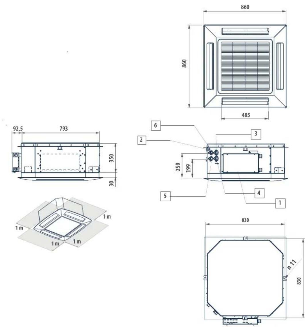
LEGENDA / LEGEND / LÉGENDE / LEGENDE / LEYENDA / VYSVĚTLIVKY / POJAŠNJENJE / LEGENDA
1)
Scatola elettrica / Electric box / Boîtier électrique / Verteilungskasten / Caja conexiones eléctricas / Llektrická skiîn / Llektricna kutija / Cut a eléctrica
2)
Scarico condensa a 10 / Condensale discharge a 10 / Purge des condensals a 10 / Kondenswasserablass a 10 / Descarga condensados a 10 / Odvod kondenzalu a 10 / Odvod kondenzata a 10 / Evacuarea condensului a 10
3)
Jusla acqua scambiatore rafredicamento 3/4" gas F / Cooling exchanger water outlet, 3/4" gas F / Sortie eau échangeur rafraîchissement 3/4" gaz F / Wassenauslass Kühlungswärmetauscher 3/4" BSP F / Salida agua intercambiador enfiamiento 3/4" gas F / Výstup vody z chladícího vyměníku 3/4" plyn F / izlaz vode iz izmjenjivača hlaženja 3/4" plin F / lejire apá schimótor de cál durá rácie 3/4" gaz F
4)
Entrata acqua scambiatore raffreddamento 3/4" gas F / Cooling exchanger water inlet, 3/4" gas F / Entrée eau échangeur rafraîchissement 3/4" gaz F / Wassereinlass kühlungswärmebauscher 3/4" BSP F / Entrada agua intercambidor entria miento 3/4" gas F / Přívod vody do chladícito výměniku 3/4" plyn F / Ulaž vode iz izmjenjivača hlađenja 3/4" plin F / Intrare apá fin schimbátor de răcire 3/4" gaz F
5)
Jscila acqua scambiatore riscaldamento 1/2" gas F / Heating exchanger water outlet, 1/2" gas F / Sonie eau échangeur chauffage 1/2" gaz F / Wasserauslass Heizungswärmetauscher 1/2" BSP F / Salida agua intercambiador calentamiento 1/2" gas F / Výstup vody z topného výmóni kú 1/2" plyn F / Izlaz vode izménjivača topline 1/2" plin F / lojire apă schimbător de căldură încălzire 1/2" gaz F
6)
Entrata acqua scambiatore riscaldamento 1/2" gas F / Heating exchanger water inlet, 1/2" gas F / Entrée eau échangeur chauffage 1/2" gaz F / Wassereinlass. Heizungswärmetauscher 1/2" BSP F / Entrada agua intercambiador calentamiento 1/2" gas F / Pflvod vody do topného výméníšu 1/2" plyn F / Ulaz vode izmjenljivača topline 1/2" plin F / Intrare apă schimbátor de cădură 1/2" gaz F
Dimensionale FWH-A 02-03-04 + FCND02A / Dimensional drawing FWH-A 02-03-04 + FCND02 / Schéma dimensionnel FWH-A 02-03-04 + FCND02 / Abmessungszeichnung FWH-A 02-03-04 + FCND02 / Dibujo dimensional FWH-A 02-03-04 + FCND02 / Rozměrový nákres FWH-A 02-03-04 + FCND02A / Dimenzionalno FWH-A 02-03-04 + FCND02A / Schiţă dimensională FWH-A 02-03-04 + FCND02A
»13.7

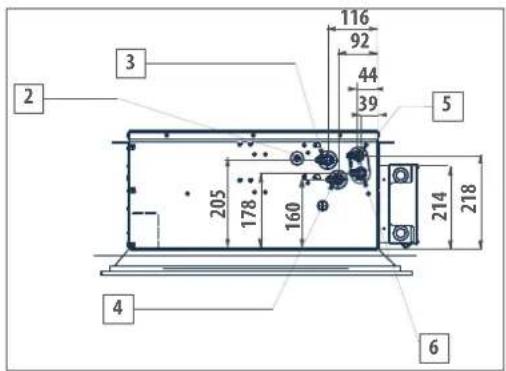
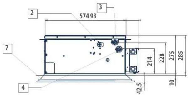
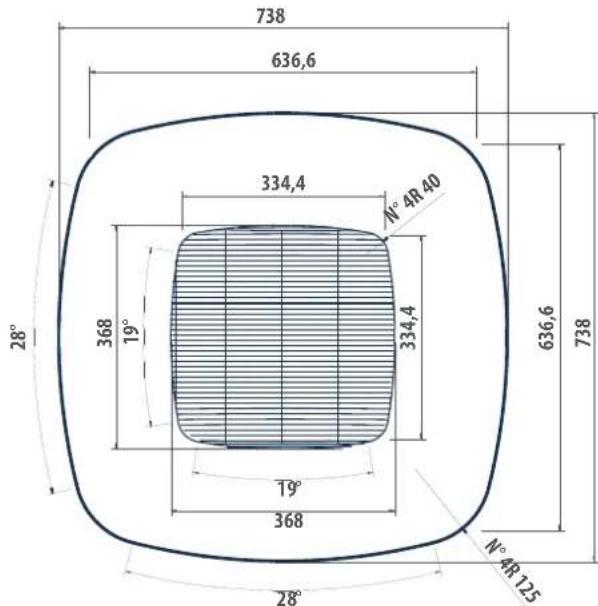
LEGENDA / LEGEND / LÉGENDE / LEGENDE / LEYENDA / VYSVĚTLIVKY / VYSVĚTLIVKY / POJAŠNJENJE / LEGENDA
1)
Scatola elettrica / Electric box / Boitier électrique / Verteilungskasten / Caja conexiones eléctricas / Liektrická skriň / Električna kurija / Cutia electrica
2)
Scarico condensa a 10 / Condensate discharge a 10 / Purge des condensars a 10 / Kondenswasserablass a 10 / Descarga condensados a 10 / Odvod kondenzatu a 10 / Odvod kondenzata a 10 / Evacuarca condensului a 10
3)
Iscita acqua scambialore raffreddamento 1/2" gas F / Cooling exchanger water outlet, 1/2" gas F / Sortie eau échangeur rafrichisement 1/2" gaz F / Wasserauslass Kuhlungswärmelauscher 1/2" BSP F / Salida agua intercambiador enfriamiento 1/2" gas F / Výstup vody z chladicho výmčníku 1/2" plyn F / Izlaz vode iz izmjonjiváca hlađenja 1/2" plin F / Ilesire apá schimbátor de cáldurá tácie 1/2" gaz F
4)
Entrata aqua scambiatore raffiedtamento 1/2" gas F / Cooling exchanger water inlet, 1/2" gas F / Entrée sau échangeur rafalchissement; 1/2" gaz F / Wassereinlass Kühlungswärmetauscher 1/2" 65P / Entrada agua intercambiador entra- miento 1/2" gas F / Přívod vočy do chladíčno výměníku 1/2" plyn F / Uliaz vode iz izmjenjivača hlađenja 1/2" plin F / Intrare apá in schimbátor de rádire 1/2" gaz F
5)
Usotia acqua scambialore riscaldamento 1/2" gas F / Healing exchanger water outlet, 1/7" gas F / Sortie eau échangeur chaufflage 1/2" gaz F / Wasserauslass Heizungswarmetauscher 1/2" BS? F / Salida agua intercambiótor calentamiento 1/2" gas F / Výstup vody z topného výměníku 1/2" plyn F / Izlaz vode izmjenjivača topline 1/2" plin F / lejiro apá schimbátor do dáldură încálzire 1/2" gaz F
6)
Entrata acqua scambiatore riscaldamento 1/2" gas F / Heating exchanger water inlet, 1/2" gas F / Entrée eau échangeur chauffage 1/2" gaz F / Wassereinlass Heizungswärmetauscher 1/2" BSP F / Entrada agua intercambiador calenamiento 1/2" gas F / Přívod vody do topného výměníku 1/2" plyn F / Ulaz vode izmjenjliváča topline 1/2" plin F / Intrare apá schimbátor de cálduřa 1/2" gaz F
» Schema elettrico Base FWH-A 02-03 3 velocità + valvola ON/OFF / Electrical wires 3 speed base FWH-A 02-03 + ON/OFF valve / Schéma électrique de base 3 vitesse FWH-A 02-03 + vanne ON/OFF / Grundschaltplan 3 Geschwindigkeit FWH-A 02-03 + ON/OFF-Ventil / Esquema eléctrico básico 3 velocidad FWH-A 02-03 + valvula ON/OFF / Elektrické schéma Base FWH-A 02-03 3 rychlost + ventil ON/OFF / Shema ožičenja Osnova FWH-A 02-03 3 brzine + ventil ON/OFF / Schema electrică de bază FWH-A 02-03 3 viteze + supapă ON/OFF
» 13.8
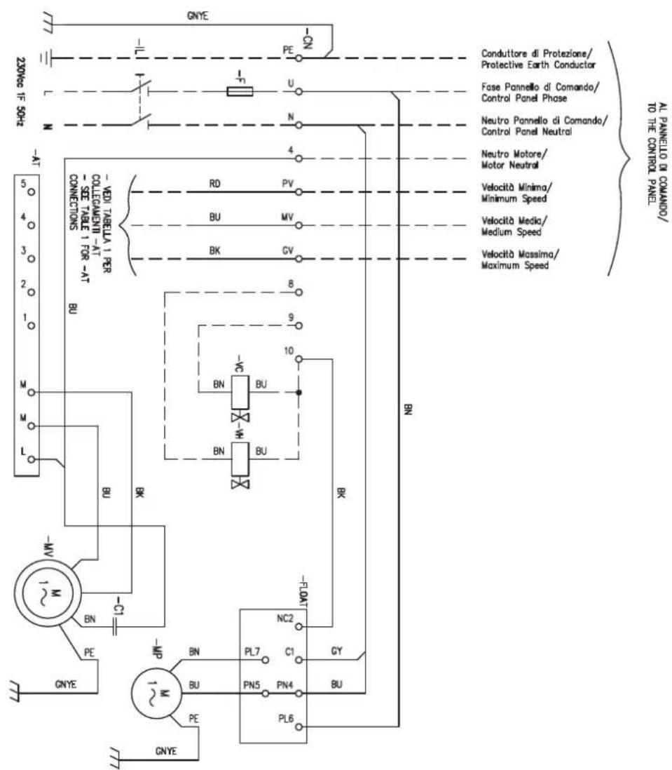
| MODELLO/MODEL | PAGE 1 | WCG66000658 |
| FHW2ZA1F | GVB(BB) -X: MV(BB) -X: PV(BB) -X: MV(BB) -X: PV(BB) -X: PV(BB) -X: PV(BB) -X: PV(BB) -X: PV(BB) -X: PV(BB) -X: PV(BB) -X: PV(BB) -X: PV(BB) -X: PV(BB) -X: PV(BB) -X: PV(BB) -X: PV(BB) -X: PV(BB) -X: PV(B8) -X: PV(B8) -X: PV(B8) -X: PV(B8) -X: PV(B8) -X: PV(B8) -X: PV(B8) -X: PV(B8) -X: PV(B8) -X: PV(B8) -X: PV(B8) -X: PV(B8) -X: PV(B8) -X: PV(B8) -X: PV(B8) | PV(B8) -X: PV(B8) -X: PV(B8) -X: PV(B8) -X: PV(B8) -X: PV(B8) -X: PV(B8) -X: PV(B8) -X: PV(B8) -X: PV(B8) -X: PV(B8) -X: PV(B8) -X: PV(B8) -X: PV(B8) -X: PV(BB) -X: PV(B8) -X: PV(B8) -X: PV(B8) -X: PV(B8) -X: PV(B8) -X: PV(B8) -X: PV(B8) -X: PV(B8) -X: PV(B8) -X: PV(B8) -X: PV(B8) -X: PV(B8) -X: PV(B8) |
» Schema elettrico Base FWH-A 04 3 velocità + valvola ON/OFF / Electrical wires 3 speed base FWH-A 04 + ON/OFF valve / Schéma électrique de base 3 vitesse FWH-A 04 + vanne ON/OFF / Grundschaltplan 3 Geschwindigkeit FWH-A 04 + ON/OFF-Ventil / Esquema eléctrico básico 3 velocidad FWH-A 04 + valvula ON/OFF / Elektrické schéma Base FWH-A 04 3 rychlost + ventil ON/OFF / Shema ožičenja Osnova FWH-A 04 3 brzine + ventil ON/OFF / Schema electrică de bază FWH-A 04 3 viteze + supapă ON/OFF
» 13.9
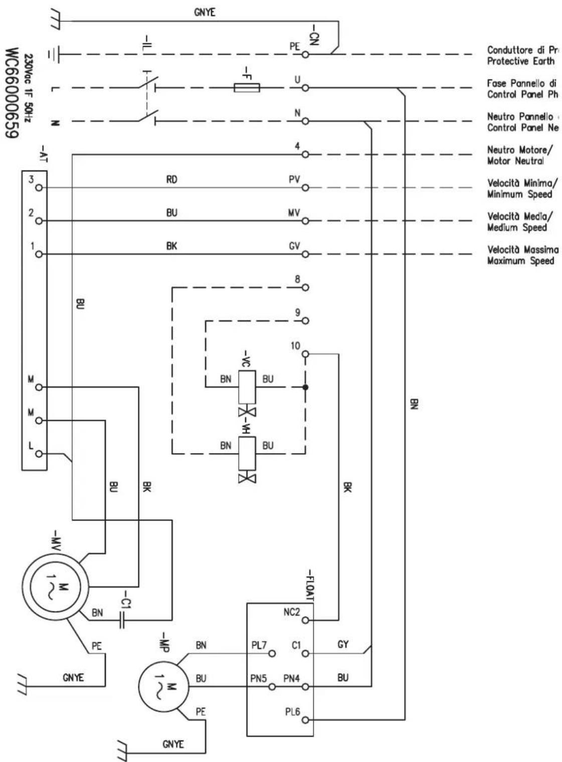
» Schema elettrico Base FWH-A 06-08 3 velocità + valvola ON/OFF / Electrical wires 3 speed base FWH-A 06-08 + ON/OFF valve / Schéma électrique de base 3 vitesse FWH-A 06-08 + vanne ON/OFF / Grundschaltplan 3 Geschwindigkeit FWH-A 06-08 + ON/OFF-Ventil / Esquema eléctrico básico 3 velocidad FWH-A 06-08 + valvula ON/OFF / Elektrické schéma Base FWH-A 06-08 3 rychlost + ventil ON/OFF / Shema ožičenja Osnova FWH-A 06-08 3 brzine + ventil ON/OFF / Schema electrică de bază FWH-A 06-08 3 viteze + supapă ON/OFF
» 13.10
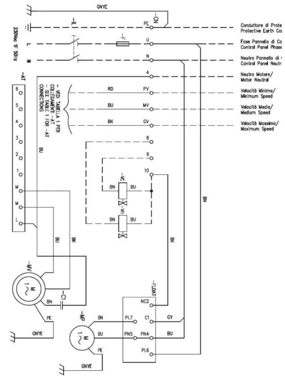
W66000660
| MODELLO/MODEL | PIN-CN-3 | PIN-A1 |
| FWH05AATT | GVB(-)3 | MVB(EU)-3; |
| FWH07AATT | GVB(-)6 | |
| FWH08AATT | GVB(-)1 | MVB(EU)-3; |
| FWH06AATT | GVB(-)5 | |
| FWH08AATT | GVB(-)3 | MVB(EU)-3; |
| FWH08AATT | GVB(-)6 |
» Schema elettrico FWEC2T FWH-A 02-03 3 velocità / FWEC2T 3 speed wiring diagram for models FWH-A 02-03 / Schéma électrique FWEC2T modèles FWH-A 02-03 3 vitesse / Schaltplan FWEC2T modellen FWH-A 02-03 3 Geschwindigkeit / Esquema eléctrico FWEC2T para modelos FWH-A 02-03 3 velocidad / Elektrické schéma FWEC2T FWH-A 02-03 3 rychlost / Shema ožičenja FWEC2T FWH-A 02-03 3 brzine / Schema de circuit FWEC2T FWH-A 02-03 3 viteze
» 13.11
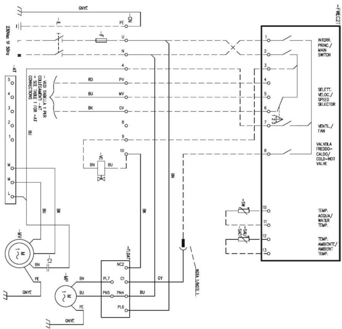
WC66000661
| NOTA: SOULICARE CAVO CYD NOSESTTOKNOTE 1: DISCONNECT THE CY CABLE FROMNOLIE -ON E COLLEAFRE A PIN 8 SU FRC2FNOTE 1: DISCONNECT THE CY CABLE FROMTERMINAL N ON-ON AND CONNECT TO PIN 8NOF FRC2F |
| TABLE 1 / TABLE 1 | Pin - CN -> Pin - AT |
| FIMH02AIF | PV(RD)->5 |
| FIMH2AIF | PV(RD)->4 |
| FIMH3AIF | PV(RD)->3 |
| FIMH3AIF | GV(BK)->1: MV(BU)->3; PV(RD)->4 |
» Schema elettrico FWEC2T FWH-A 04 3 velocità / FWEC2T 3 speed wiring diagram for models FWH-A 04 / Schéma électrique FWEC2T modèles FWH-A 04 3 vitesse / Schaltplan FWEC2T modellen FWH-A 04 3 Geschwindigkeit / Esquema eléctrico FWEC2T para modelos FWH-A 04 3 velocidad / Elektrické schéma FWEC2T FWH-A 04 3 rychlost / Shema ožičenja FWEC2T FWH-A 04 3 brzine / Schema de circuit FWEC2T FWH-A 04 3 viteze
» 13.12
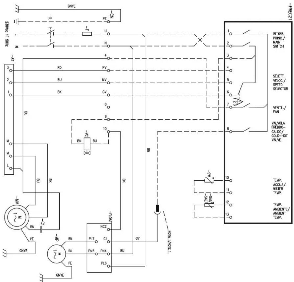
W66000662 NO FIRST TEAAAA N O -ON AND CONNECT TO PIN B NOTE 1: DISCONNECT THE OF CABLE FROM N SU -ON E COLLECTIVE A PIN B SU FIRST NO IA 1: SCULFERENCE CHAP OR DA WORKSITIO
» Schema elettrico FWEC2T FWH-A 06-08 3 velocità / FWEC2T 3 speed wiring diagram for models FWH-A 06-08 / Schéma électrique FWEC2T modèles FWH-A 06-08 3 vitesse / Schaltplan FWEC2T modellen FWH-A 06-08 3 Geschwindigkeit / Esquema eléctrico FWEC2T para modelos FWH-A 06-08 3 velocidad / Elektrické schéma FWEC2T FWH-A 06-08 3 rychlost / Shema ožičenja FWEC2T FWH-A 06-08 3 brzine / Schema de circuit FWEC2T FWH-A 06-08 3 viteze
» 13.13
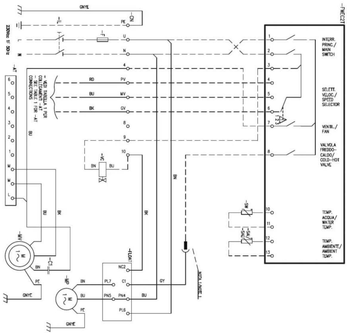
| MODELLO/MODE. | PN - CN -> PN - AT |
| FWH06A4F | OV(BX) ->3: MV(BU) ->3: PV(BG) ->3: PV(RG) ->3: |
| FWH06A4F | OV(BX) ->3: MV(BU) ->3: PV(RG) ->3: |
| FWH08A4F | OV(BX) ->3: MV(BU) ->3: PV(RG) ->3: |
| FWH06A4T | OV(BX) ->3: MV(BU) ->3: PV(RG) ->3: |
| FWH07A4T | PV(BG) ->3: |
» Schema elettrico FWEC4T FWH-A 02-03 3 velocità / FWEC4T 3 speed wiring diagram for models FWH-A 02-03 / Schéma électrique FWEC4T modèles FWH-A 02-03 3 vitesse / Schaltplan FWEC4T modellen FWH-A 02-03 3 Geschwindigkeit / Esquema eléctrico FWEC4T para modelos FWH-A 02-03 3 velocidad / Elektrické schéma FWEC4T FWH-A 02-03 3 rychlost / Shema ožičenja FWEC4T FWH-A 02-03 3 brzine / Schema de circuit FWEC4T FWH-A 02-03 3 viteze
» 13.14
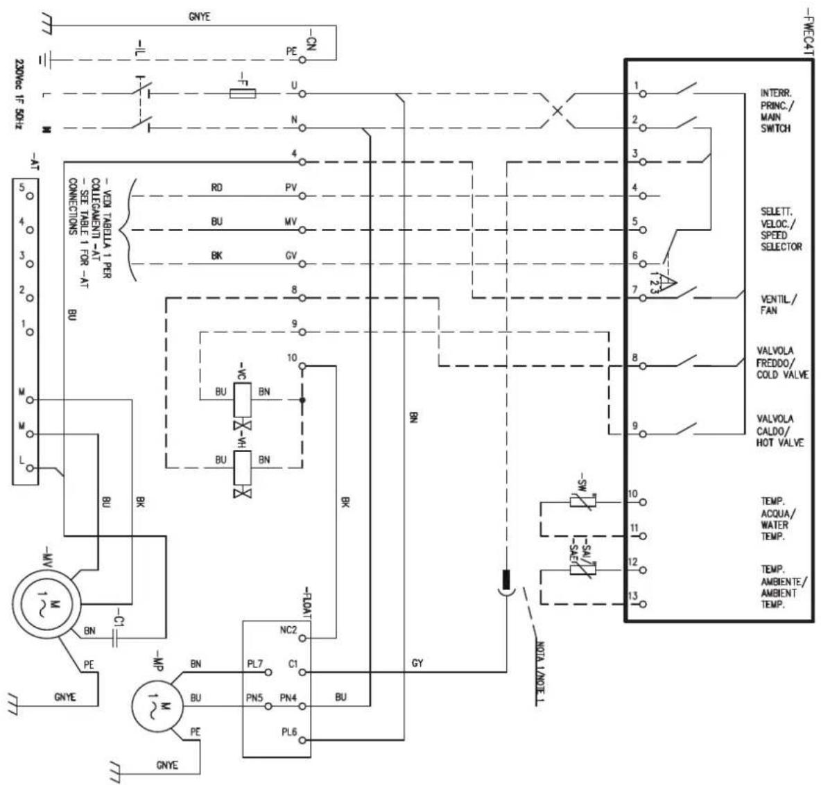
NOTA: SOULICARE CAVO BY DA WORKSITTO N SU -ON E COOLICARE A PIN 3 SU PROCET NOTE: DISCONNECT THE CY CABLE FROM TERMINAL N ON -ON AND CONNECT TO PIN 3 ON PROCET
| TABLE 1 / TABLE 1 | Pin -ON -> Pin -AT |
| FIMH2AAT1 | GV(BK) ->2: MV(BU) ->3: PV(RG) ->5 |
| FIMH2AAT1 | GV(BK) ->2: MV(BU) ->3: PV(RG) ->5 |
| FIMH2AAT1 | GV(BK) ->1: MV(BU) ->3: PV(RG) ->4 |
WC66000663
» Schema elettrico FWEC4T FWH-A 04 3 velocità / FWEC4T 3 speed wiring diagram for models FWH-A 04 / Schéma électrique FWEC4T modèles FWH-A 04 3 vitesse / Schaltplan FWEC4T modellen FWH-A 04 3 Geschwindigkeit / Esquema eléctrico FWEC4T para modelos FWH-A 04 3 velocidad / Elektrické schéma FWEC4T FWH-A 04 3 rychlost / Shema ožičenja FWEC4T FWH-A 04 3 brzine / Schema de circuit FWEC4T FWH-A 04 3 viteze
» 13.15
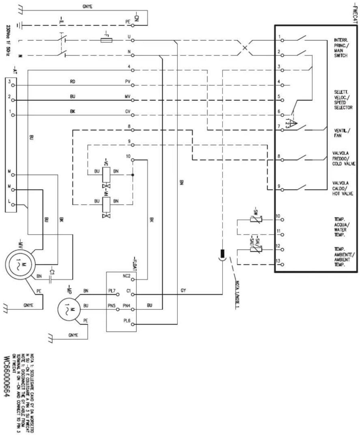
» Schema elettrico FWEC4T FWH-A 06-08 3 velocità / FWEC4T 3 speed wiring diagram for models FWH-A 06-08 / Schéma électrique FWEC4T modèles FWH-A 06-08 3 vitesse / Schaltplan FWEC4T modellen FWH-A 06-08 / Esquema eléctrico FWEC4T para modelos FWH-A 06-08 3 velocidad / Elektrické schéma FWEC4T FWH-A 06-08 3 rychlost / Shema ožičenja FWEC4T FWH-A 06-08 3 brzine / Schema de circuit FWEC4T FWH-A 06-08 3 viteze
» 13.16
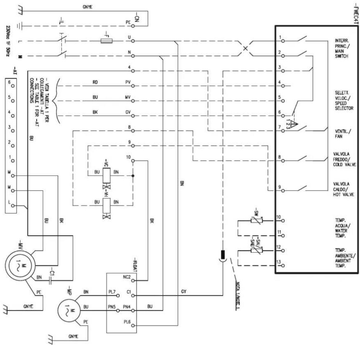
WC66000494
| NOTA: SOOLIEABLE CAVO BY DA WORKS TLO N SU-ON E COOLIEABLE A PIN 3 SU FINICAT NOTE I: DISCONNECT THE CY CALLIC FROM TERMINAL N ON-ON AND CONNECT TO PIN 3 ON FINICAT |
| MODELLO/MODE. | Pin-CN->Pin-AT |
| FIM06A1FIM07A1FIM08A1FIM09A1FIM06A1FIM08A4FIM09A4FIM08A5FIM09A5FIM08A6FIM09A6FIM08A7FIM09A7FIM08A8FIM09A8FIM08A9FIM09A9FIM08A10FIM09A11FIM09A12FIM09A13FIM09A14FIM09A15FIM09A16FIM09A17FIM09A18FIM09A19FIM09A20FIM09A21FIM09A22FIM09A23FIM09A24FIM09A25FIM09A26FIM09A27FIM09A28FIM09A29FIM09A30FIM09A31FIM09A32FIM09A33FIM09A34FIM09A35FIM09A36FIM09A37FIM09A38FIM09A39FIM09A40FIM09A41FIM09A42FIM09A43FIM09A44FIM09A45FIM09A46FIM09A47FIM09A48FIM09A49FIM09A50FIM09A51FIM09A52FIM09A53FIM09A54FIM09A55FIM09A56FIM09A57FIM09A58FIM09A59FIM09A60FIM09A61FIM09A62FIM09A63FIM09A64FIM09A65FIM09A66FIM09A67FIM09A68FIM09A69FIM09A70FIM09A71FIM09A72FIM09A73FIM09A74FIM09A75FIM09A76FIM09A77FIM09A78FIM09A79FIM09A80FIM09A81FIM09A82FIM09A83FIM09A84FIM09A85FIM09A86FIM09A87FIM09A88FIM09A89FIM09A90FIM09A91FIM09A92FIM09A93FIM09A94FIM09A95FIM09A96FIM09A97FIM09A98FIM09A99FIM09A100FIM09A101FIM09A102FIM09A103FIM09A104FIM09A105FIM09A106FIM09A107FIM09A108FIM09A109FIM09A110FIM09A111FIM09A112FIM09A113FIM09A114FIM09A115FIM09A116FIM09A117FIM09A118FIM09A119FIM09A120FIM09A121FIM09A122FIM09A123FIM09A124FIM09A125FIM09A126FIM09A127FIM09A128FIM09A129FIM09A130FIM09A131FIM09A132FIM09A133FIM09A134FIM09A135FIM09A136FIM09A137FIM09A138FIM09A139FIM09A140FIM09A141FIM09A142FIM09A143FIM09A144FIM09A145FIM09A146FIM09A147FIM09A148FIM09A149FIM09A150FIM09A151FIM09A152FIM09A153FIM09A154FIM09A155FIM09A156FIM09A157FIM09A158FIM09A159FIM09A160FIM09A161FIM09A162FIM09A163FIM09A164FIM09A165FIM09A166FIM09A167FIM09A168FIM09A169FIM09A170FIM09A171FIM09A172FIM09A173FIM09A174FIM09A175FIM09A176FIM09A177FIM09A178FIM09A179FIM09A180FIM09A181FIM09A182FIM09A183FIM09A184FIM09A185FIM09A186FIM09A187FIM09A188FIM09A189FIM09A190FIM09A191FIM09A192FIM09A193FIM09A194FIM09A195FIM09A196FIM09A197FIM09A198FIM09A199FIM09A200FIM09A201FIM09A202FIM09A203FIM09A204FIM09A205FIM09A206FIM09A207FIM09A208FIM09A209FIM09A210FIM09A211FIM09A212FIM09A213FIM09A214FIM09A215FIM09A216FIM09A217FIM09A218FIM09A219FIM09A220FIM09A221FIM09A222FIM09A223FIM09A224FIM09A225FIM09A226FIM09A227FIM09A228FIM09A229FIM09A230FIM09A231FIM09A232FIM09A233FIM09A234FIM09A235FIM09A236FIM09A237FIM09A238FIM09A239FIM09A240FIM09A241FIM09A242FIM09A243FIM09A244FIM09A245FIM09A246FIM09A247FIM09A248FIM09A249FIM09A250FIM09A251FIM09A252FIM09A253FIM09A254FIM09A255FIM09A256FIM09A257FIM09A258FIM09A259FIM09A260FIM09A261FIM09A262FIM09A263FIM09A264FIM09A265FIM09A266FIM09A267FIM09A268FIM09A269FIM09A270FIM09A271FIM09A272FIM09A273FIM09A274FIM09A275FIM09A276FIM09A277FIM09A278FIM09A279FIM09A280FIM09A281FIM09A282FIM09A283FIM09A284FIM09A285FIM09A286FIM09A287FIM09A288FIM09A289FIM09A290FIM09A291FIM09A292FIM09A293FIM09A294FIM09A295FIM09A296FIM09A297FIM09A298FIM09A299FIM09A300FIM09A301FIM09A302FIM09A303FIM09A304FIM09A305FIM09A306FIM09A307FIM09A308FIM09A309FIM09A310FIM09A311FIM09A312FIM09A313FIM09A314FIM09A315FIM09A316FIM09A317FIM09A318FIM09A319FIM09A320FIM09A321FIM09A322FIM09A323FIM09A324FIM09A325FIM09A326FIM09A327FIM09A328FIM09A329FIM09A330FIM09A331FIM09A332FIM09A333FIM09A334FIM09A335FIM09A336FIM09A337FIM09A338FIM09A339FIM09A340FIM09A341FIM09A342FIM09A343FIM09A344FIM09A345FIM09A346FIM09A347FIM09A348FIM09A349FIM09A350FIM09A351FIM09A352FIM09A353FIM09A354FIM09A355FIM09A356FIM09A357FIM09A358FIM09A359FIM09A360FIM09A361FIM09A362FIM09A363FIM09A364FIM09A365FIM09A366FIM09A367FIM09A368FIM09A369FIM09A370FIM09A371FIM09A372FIM09A373FIM09A374FIM09A375FIM09A376FIM09A377FIM09A378FIM09A379FIM09A380FIM09A381FIM09A382FIM09A383FIM09A384FIM09A385FIM09A386FIM09A387FIM09A388FIM09A389FIM09A390FIM09A391FIM09A392FIM09A393FIM09A394FIM09A395FIM09A396FIM09A397FIM09A398FIM09A399FIM09A400FIM09A401FIM09A402FIM09A403FIM09A404FIM09A405FIM09A406FIM09A407FIM09A408FIM09A409FIM09A410FIM09A411FIM09A412FIM09A413FIM09A414FIM09A415FIM09A416FIM09A417FIM09A418FIM09A419FIM09A420FIM09A421FIM09A422FIM09A423FIM09A424FIM09A425FIM09A426FIM09A427FIM09A428FIM09A429FIM09A430FIM09A431FIM09A432FIM09A433FIM09A434FIM09A435FIM09A436FIM09A437FIM09A438FIM09A439FIM09A440FIM09A441FIM09A442FIM09A443FIM09A444FIM09A445FIM09A446FIM09A447FIM09A448FIM09A449FIM09A450FIM09A451FIM09A452FIM09A453FIM09A454FIM09A455FIM09A456FIM09A457FIM09A458FIM09A459FIM09A460FIM09A461FIM09A462FIM09A463FIM09A464FIM09A465FIM09A466FIM09A467FIM09A468FIM09A469FIM09A470FIM09A471FIM09A472FIM09A473FIM09A474FIM09A475FIM09A476FIM09A477FIM09A478FIM09A479FIM09A480FIM09A481FIM09A482FIM09A483FIM09A484FIM09A485FIM09A486FIM09A487FIM09A488FIM09A489FIM09A490FIM09A491FIM09A492FIM09A493FIM09A494FIM09A495FIM09A496FIM09A497FIM09A498FIM09A499FIM09A500FIM09A501FIM09A502FIM09A503FIM09A504FIM09A505FIM09A506FIM09A507FIM09A508FIM09A509FIM09A510FIM09A511FIM09A512FIM09A513FIM09A514FIM09A515FIM09A516FIM09A517FIM09A518FIM09A519FIM09A520FIM09A521FIM09A522FIM09A523FIM09A524FIM09A525FIM09A526FIM09A527FIM09A528FIM09A529FIM09A530FIM09A531FIM09A532FIM09A533FIM09A534FIM09A535FIM09A536FIM09A537FIM09A538FIM09A539FIM09A540FIM09A541FIM09A542FIM09A543FIM09A544FIM09A545FIM09A546FIM09A547FIM09A548FIM09A549FIM09A550FIM09A551FIM09A552FIM09A553FIM09A554FIM09A555FIM09A556FIM09A557FIM09A558FIM09A559FIM09A560FIM09A561FIM09A562FIM09A563FIM09A564FIM09A565FIM09A566FIM09A567FIM09A568FIM09A569FIM09A570FIM09A571FIM09A572FIM09A573FIM09A574FIM09A575FIM09A576FIM09A577FIM09A578FIM09A579FIM09A580FIM09A581FIM09A582FIM09A583FIM09A584FIM09A585FIM09A586FIM09A587FIM09A588FIM09A589FIM09A590FIM09A591FIM09A592FIM09A593FIM09A594FIM09A595FIM09A596FIM09A597FIM09A598FIM09A599FIM09A600FIM09A601FIM09A602FIM09A603FIM09A604FIM09A605FIM09A606FIM09A607FIM09A608FIM09A609FIM09A610FIM09A611FIM09A612FIM09A613FIM09A614FIM09A615FIM09A616FIM09A617FIM09A618FIM09A619FIM09A620FIM09A621FIM09A622FIM09A623FIM09A624FIM09A625FIM09A626FIM09A627FIM09A628FIM09A629FIM09A630FIM09A631FIM09A632FIM09A633FIM09A634FIM09A635FIM09A636FIM09A637FIM09A638FIM09A639FIM09A640FIM09A641FIM09A642FIM09A643FIM09A644FIM09A645FIM09A646FIM09A647FIM09A648FIM09A649FIM09A650FIM09A651FIM09A652FIM09A653FIM09A654FIM09A655FIM09A656FIM09A657FIM09A658FIM09A659FIM09A660FIM09A661FIM09A662FIM09A663FIM09A664FIM09A665FIM09A666FIM09A667FIM09A668FIM09A669FIM09A670FIM09A671FIM09A672FIM09A673FIM09A674FIM09A675FIM09A676FIM09A677FIM09A678FIM09A679FIM09A680FIM09A681FIM09A682FIM09A683FIM09A684FIM09A685FIM09A686FIM09A687FIM09A688FIM09A689FIM09A690FIM09A691FIM09A692FIM09A693FIM09A694FIM09A695FIM09A696FIM09A697FIM09A698FIM09A699FIM09A700FIM09A701FIM09A702FIM09A703FIM09A704FIM09A705FIM09A706FIM09A707FIM09A708FIM09A709FIM09A710FIM09A711FIM09A712FIM09A713FIM09A714FIM09A715FIM09A716FIM09A717FIM09A718FIM09A719FIM09A720FIM09A721FIM09A722FIM09A723FIM09A724FIM09A725FIM09A726FIM09A727FIM09A728FIM09A729FIM09A730FIM09A731FIM09A732FIM09A733FIM09A734FIM09A735FIM09A736FIM09A737FIM09A738FIM09A739FIM09A740FIM09A741FIM09A742FIM09A743FIM09A744FIM09A745FIM09A746FIM09A747FIM09A748FIM09A749FIM09A750FIM09A751FIM09A752FIM09A753FIM09A754FIM09A755FIM09A756FIM09A757FIM09A758FIM09A759FIM09A760FIM09A761FIM09A762FIM09A763FIM09A764FIM09A765FIM09A766FIM09A767FIM09A768FIM09A769FIM09A770FIM09A771FIM09A772FIM09A773FIM09A774FIM09A775FIM09A776FIM09A777FIM09A778FIM09A779FIM09A780FIM09A781FIM09A782FIM09A783FIM09A784FIM09A785FIM09A786FIM09A787FIM09A788FIM09A789FIM09A790FIM09A791FIM09A792FIM09A793FIM09A794FIM09A795FIM09A796FIM09A797FIM09A798FIM09A799FIM09A800FIM09A801FIM09A802FIM09A803FIM09A804FIM09A805FIM09A806FIM09A807FIM09A808FIM09A809FIM09A810FIM09A811FIM09A812FIM09A813FIM09A814FIM09A815FIM09A816FIM09A817FIM09A818FIM09A819FIM09A820FIM09A821FIM09A822FIM09A823FIM09A824FIM09A825FIM09A826FIM09A827FIM09A828FIM09A829FIM09A830FIM09A831FIM09A832FIM09A833FIM09A834FIM09A835FIM09A836FIM09A837FIM09A838FIM09A839FIM09A840FIM09A841FIM09A842FIM09A843FIM09A844FIM09A845FIM09A846FIM09A847FIM09A848FIM09A849FIM09A850FIM09A851FIM09A852FIM09A853FIM09A854FIM09A855FIM09A856FIM09A857FIM09A858FIM09A859FIM09A860FIM09A861FIM09A862FIM09A863FIM09A864FIM09A865FIM09A866FIM09A867FIM09A868FIM09A869FIM09A870FIM09A871FIM09A872FIM09A873FIM09A874FIM09A875FIM09A876FIM09A877FIM09A878FIM09A879FIM09A880FIM09A881FIM09A882FIM09A883FIM09A884FIM09A885FIM09A886FIM09A887FIM09A888FIM09A889FIM09A890FIM09A891FIM09A892FIM09A893FIM09A894FIM09A895FIM09A896FIM09A897FIM09A898FIM09A899FIM09A900FIM09A901FIM09A902FIM09A903FIM09A904FIM09A905FIM09A906FIM09A907FIM09A908FIM09A909FIM09A910FIM09A911FIM09A912FIM09A913FIM09A914FIM09A915FIM09A916FIM09A917FIM09A918FIM09A919FIM09A920FIM09A921FIM09A922FIM09A923FIM09A924FIM09A925FIM09A926FIM09A927FIM09A928FIM09A929FIM09A930FIM09A931FIM09A932FIM09A933FIM09A934FIM09A935FIM09A936FIM09A937FIM09A938FIM09A939FIM09A940FIM09A941FIM09A942FIM09A943FIM09A944FIM09A945 FIM 1 | |
» Schema elettrico FWEC1A FWH-A 02-03 3 velocità / FWEC1A 3 speed wiring diagram for FWH-A 02-03 / Schéma électrique FWEC1A FWH-A 02-03 3 vitesse / Schaltplan FWEC1A FWH-A 02-03 3 Geschwindigkeit / Esquema eléctrico FWEC1A FWH-A 02-03 3 velocidad / Elektrické schéma FWEC1A FWH-A 02-03 3 rychlost / Shema ožičenja FWEC1A FWH-A 02-03 3 brzine / Schema de circuit FWEC1A FWH-A 02-03 3 viteze
» 13.17
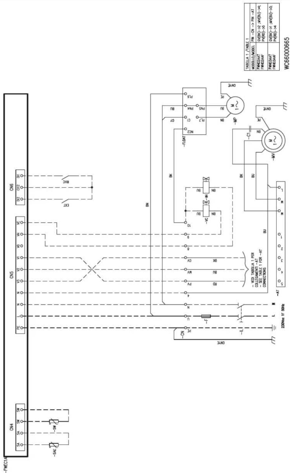
» Schema elettrico FWEC1A FWH-A 04 3 velocità / FWEC1A 3 speed wiring diagram for FWH-A 04 / Schéma électrique FWEC1A FWH-A 04 3 vitesse / Schaltplan FWEC1A FWH-A 04 3 Geschwindigkeit / Esquema eléctrico FWEC1A FWH-A 04 3 velocidad / Elektrické schéma FWEC1A FWH-A 04 3 rychlost / Shema ožičenja FWEC1A FWH-A 04 3 brzine / Schema de circuit FWEC1A FWH-A 04 3 viteze
» 13.18
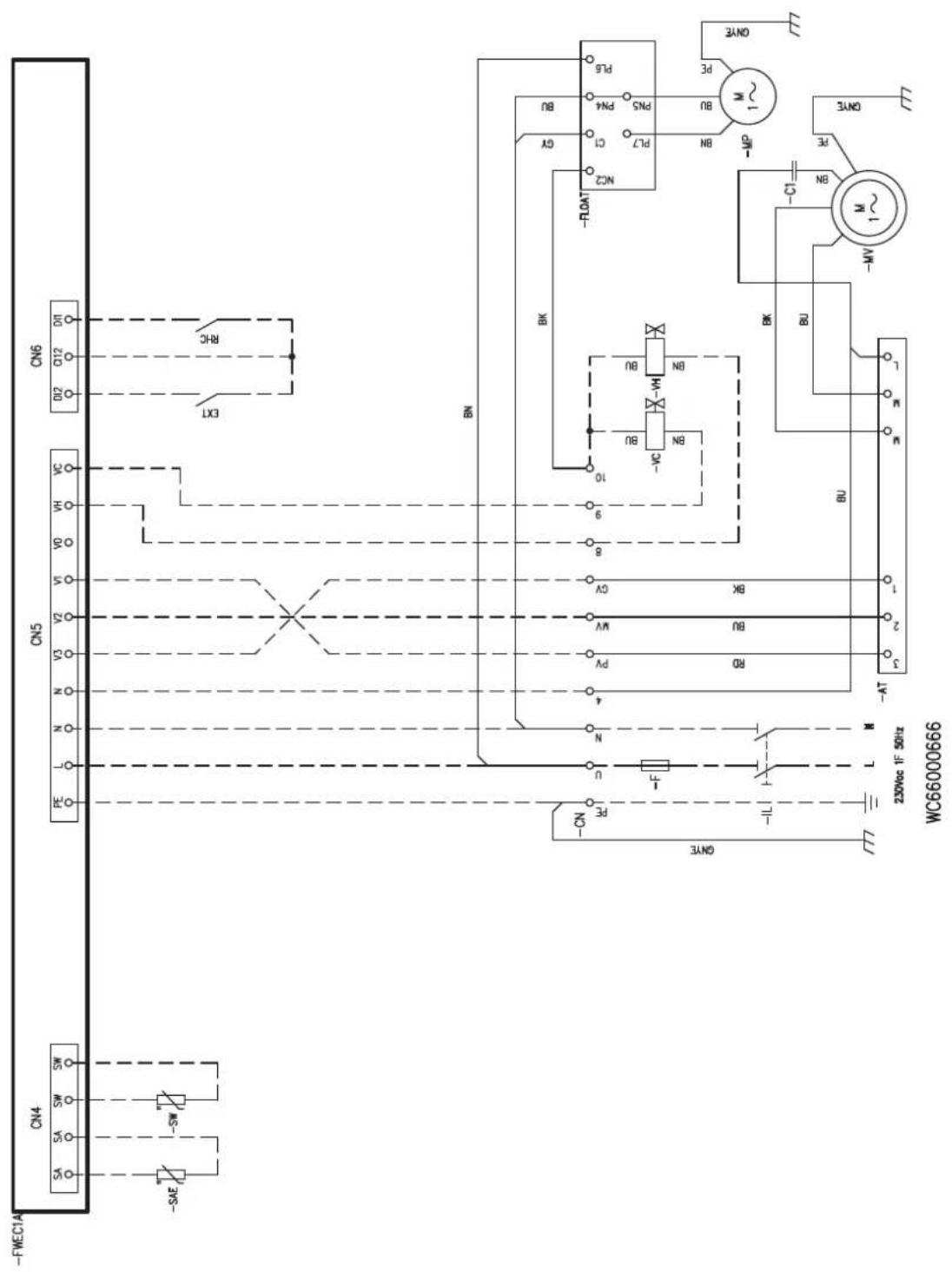
» Schema elettrico FWEC1A FWH-A 06-08 3 velocità / FWEC1A 3 speed wiring diagram for FWH-A 06-08 / Schéma électrique FWEC1A FWH-A 06-08 3 vitesse / Schaltplan My Comfort Base FWH-A 06-08 3 Geschwindigkeit / Esquema eléctrico FWEC1A FWH-A 06-08 3 velocidad / Elektrické schéma FWEC1A FWH-A 06-08 3 rychlost / Shema ožičenja FWEC1A FWH-A 06-08 3 brzine / Schema de circuit FWEC1A FWH-A 06-08 3 viteze
» 13.19
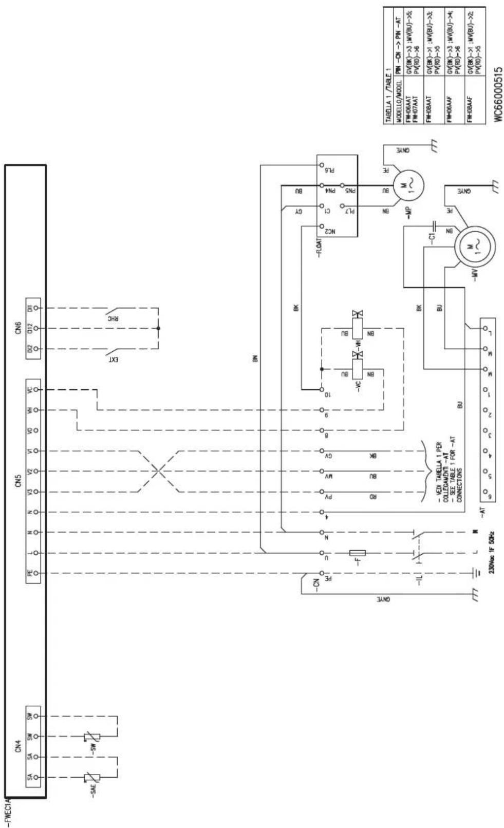
» Schema elettrico FWEC2A FWH-A 02-03 3 velocità / FWEC2A 3 speed wiring diagram for FWH-A 02-03 / Schéma électrique FWEC2A FWH-A 02-03 3 vitesse / Schaltplan FWEC2A FWH-A 02-03 3 Geschwindigkeit / Esquema eléctrico FWEC2A FWH-A 02-03 3 velocidad / Elektrické schéma FWEC2A FWH-A 02-03 3 rychlost / Shema ožičenja FWEC2A FWH-A 02-03 3 brzine / Schema de circuit FWEC2A FWH-A 02-03 3 viteze
» 13.20
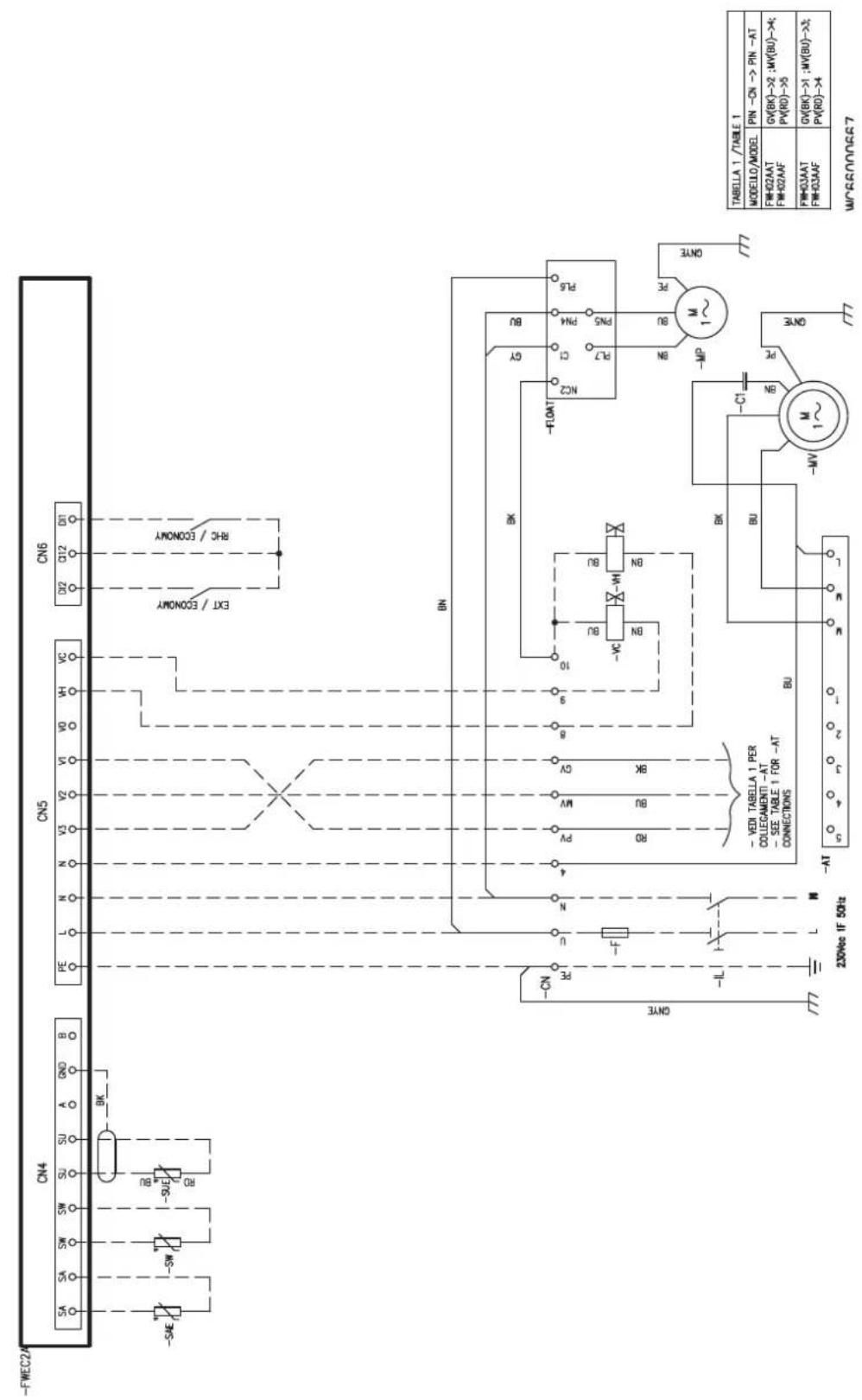
» Schema elettrico FWEC2A FWH-A 04 3 velocità / FWEC2A 3 speed wiring diagram for FWH-A 04 / Schéma électrique FWEC2A FWH-A 04 3 vitesse / Schaltplan FWEC2A FWH-A 04 3 Geschwindigkeit / Esquema eléctrico FWEC2A FWH-A 04 3 velocidad / Elektrické schéma FWEC2A FWH-A 04 3 rychlost / Shema ožičenja FWEC2A FWH-A 04 3 brzine / Schema de circuit FWEC2A FWH-A 04 3 viteze
» 13.21
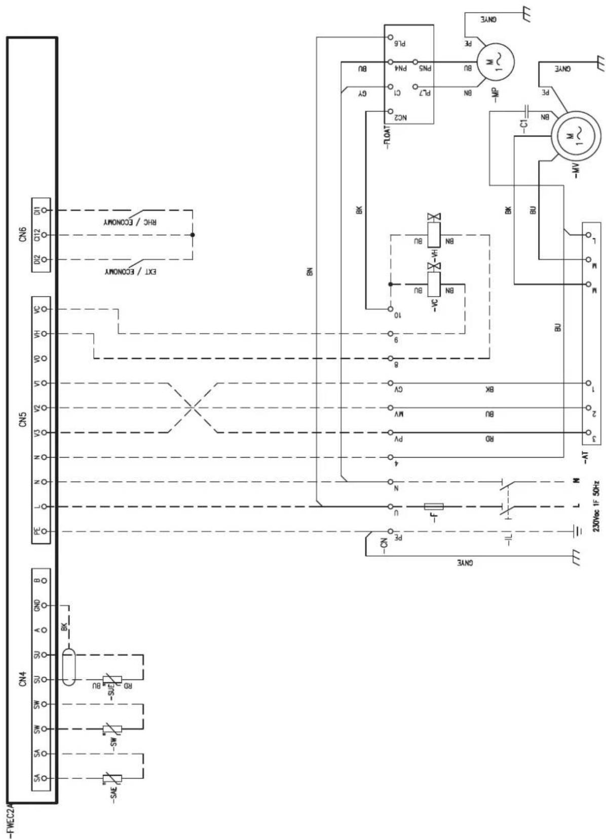
» Schema elettrico FWEC2A FWH-A 06-08 3 velocità / FWEC2A 3 speed wiring diagram for FWH-A 06-08 / Schéma électrique FWEC2A FWH-A 06-08 3 vitesse / Schaltplan FWEC2A FWH-A 06-08 3 Geschwindigkeit / Esquema eléctrico FWEC2A FWH-A 06-08 3 velocidad / Elektrické schéma FWEC2A FWH-A 06-08 3 rychlost / Shema ožičenja FWEC2A FWH-A 06-08 3 brzine / Schema de circuit FWEC2A FWH-A 06-08 3 viteze
» 13.22
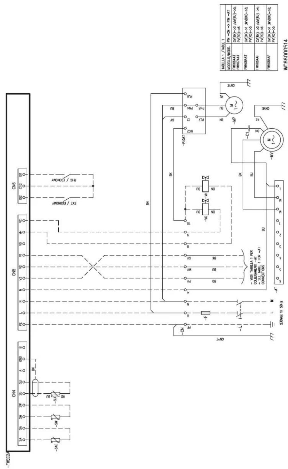
» Schema elettrico FWEC3A FWH-A 02-03 3 velocità / FWEC3A 3 speed wiring diagram for models FWH-A 02-03 / Schéma électrique FWEC3A FWH-A 02-03 3 vitesse / Schaltplan FWEC3A FWH-A 02-03 3 Geschwindigkeit / Esquema eléctrico FWEC3A para modelos FWH-A 02-03 3 velocidad / Elektrické schéma FWEC3A FWH-A 02-03 3 rychlost / Shema ožičenja FWEC3A FWH-A 02-03 3 brzine / Schema de circuit FWEC3A FWH-A 02-03 3 viteze
» 13.23
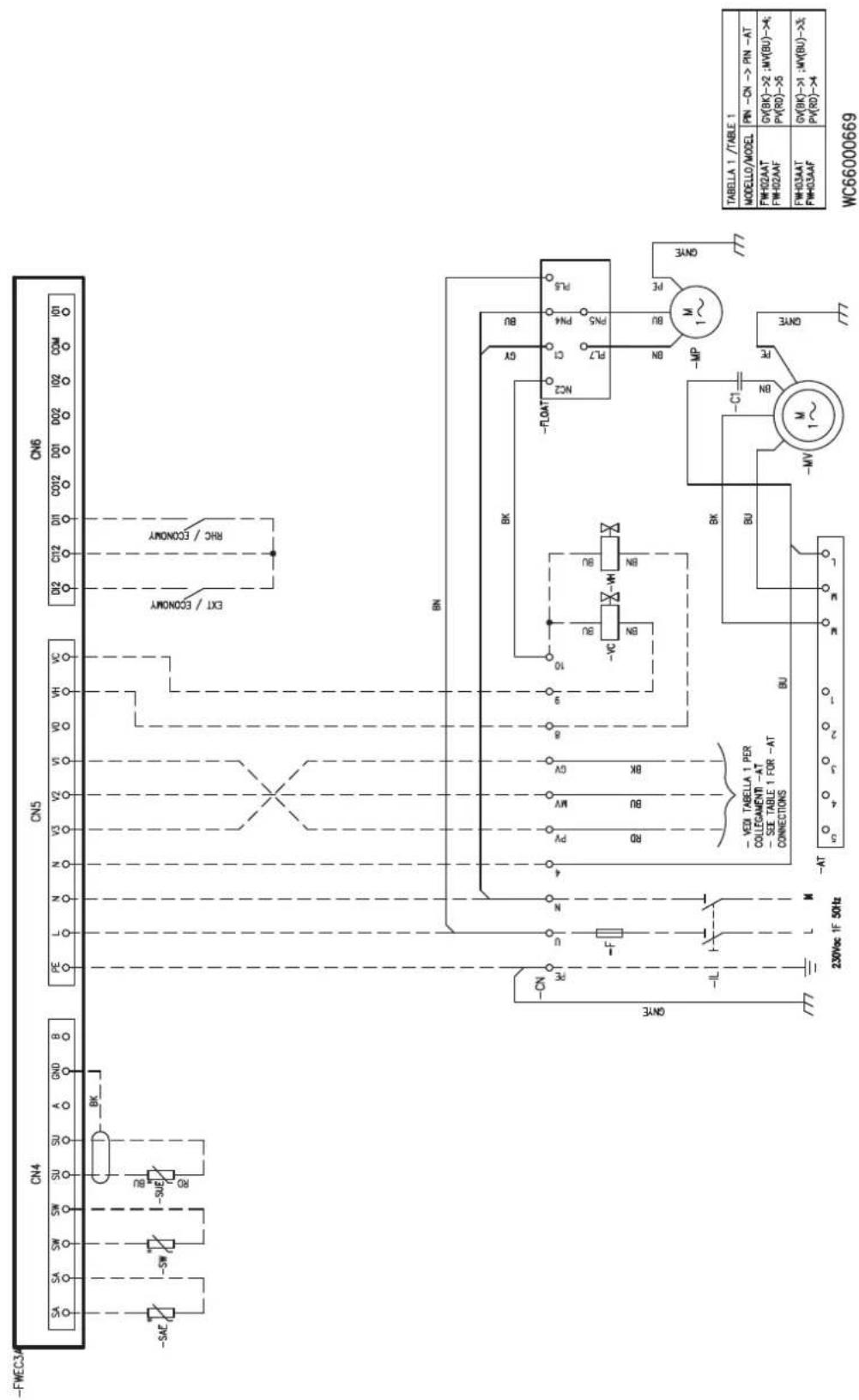
» Schema elettrico FWEC3A FWH-A 04 3 velocità / FWEC3A 3 speed wiring diagram for models FWH-A 04 / Schéma électrique FWEC3A FWH-A 04 3 vitesse / Schaltplan FWEC3A FWH-A 04 3 Geschwindigkeit / Esquema eléctrico FWEC3A FWH-A 04 3 velocidad / Elektrické schéma FWEC3A FWH-A 04 3 rychlost / Shema ožičenja FWEC3A FWH-A 04 3 brzine / Schema de circuit FWEC3A FWH-A 04 3 viteze
» 13.24
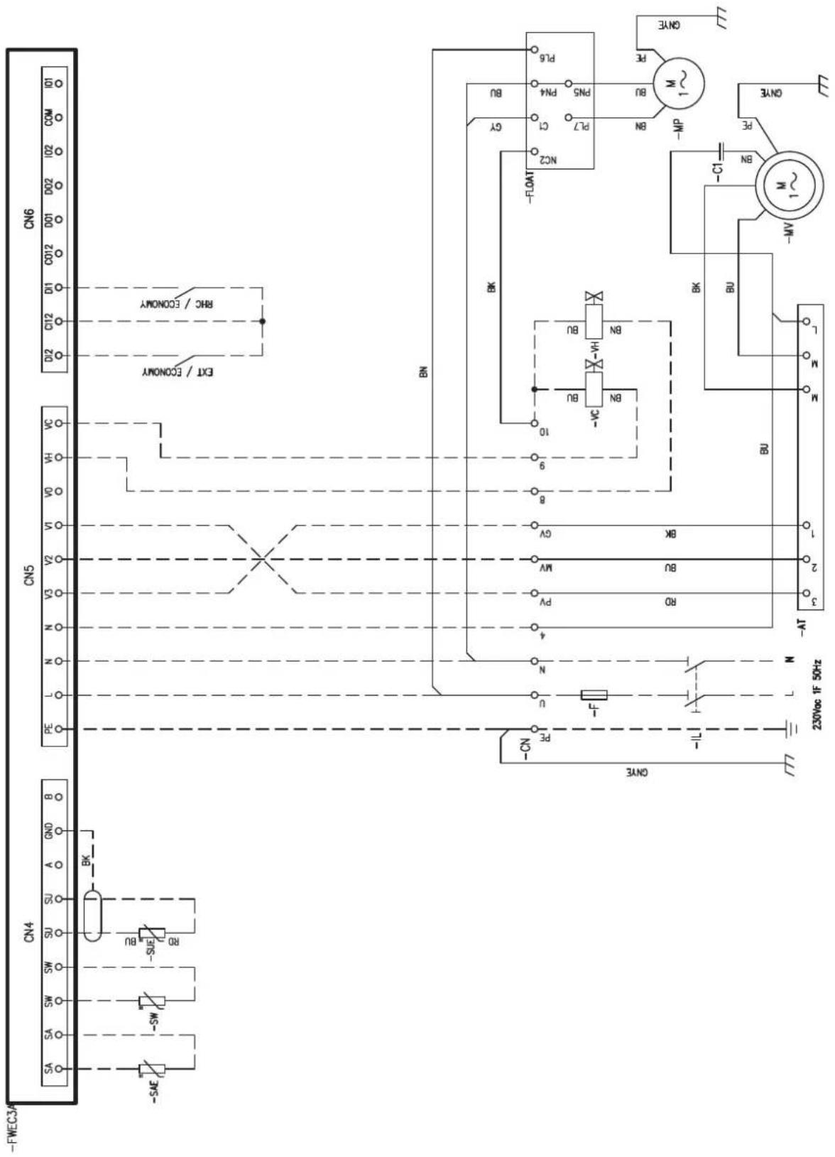
» Schema elettrico FWEC3A FWH-A 06-08 3 velocità / FWEC3A 3 speed wiring diagram for models FWH-A 06-08 / Schéma électrique FWEC3A FWH-A 06-08 3 vitesse / Schaltplan FWEC3A Modelle FWH-A 06-08 3 Geschwindigkeit / Esquema eléctrico FWEC3A para modelos FWH-A 06-08 3 velocidad / Elektrické schéma FWEC3A FWH-A 06-08 3 rychlost / Shema ožičenja FWEC3A FWH-A 06-08 3 brzine / Schema de circuit FWEC3A FWH-A 06-08 3 viteze
» 13.25
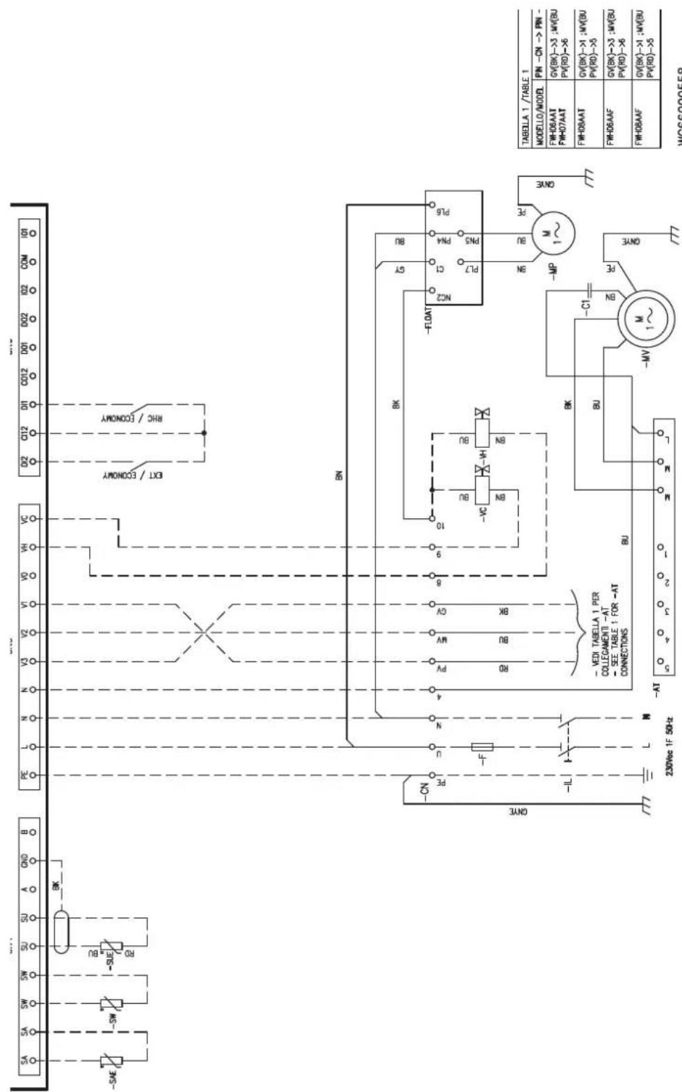
» Schema elettrico FWECSA per modelli FWH-A 02-03 3 velocità + valvola ON/OFF / FWECSA 3 speed wiring diagram for models FWH-A 02-03 + ON/OFF valve / Schéma électrique de FWECSA 3 vitesse FWH-A 02-03 + vanne ON/OFF / Schaltplan FWECSA für Modelle FWH-A 02-03 3 Geschwindigkeit + ON/OFF-Ventil / Esquema eléctrico FWECSA para modelos FWH-A 02-03 3 velocidad + valvula ON/OFF / Elektrické schéma FWECSA pro modely FWH-A 02-03 3 rychlost + ventil ON/OFF / Shema ožičenja FWECSA za modele FWH-A 02-03 3 brzine + ventil ON/OFF / Schema de circuit FWECSA pentru FWH-A 02-03 3 viteze + supapă ON/OFF
» 13.26
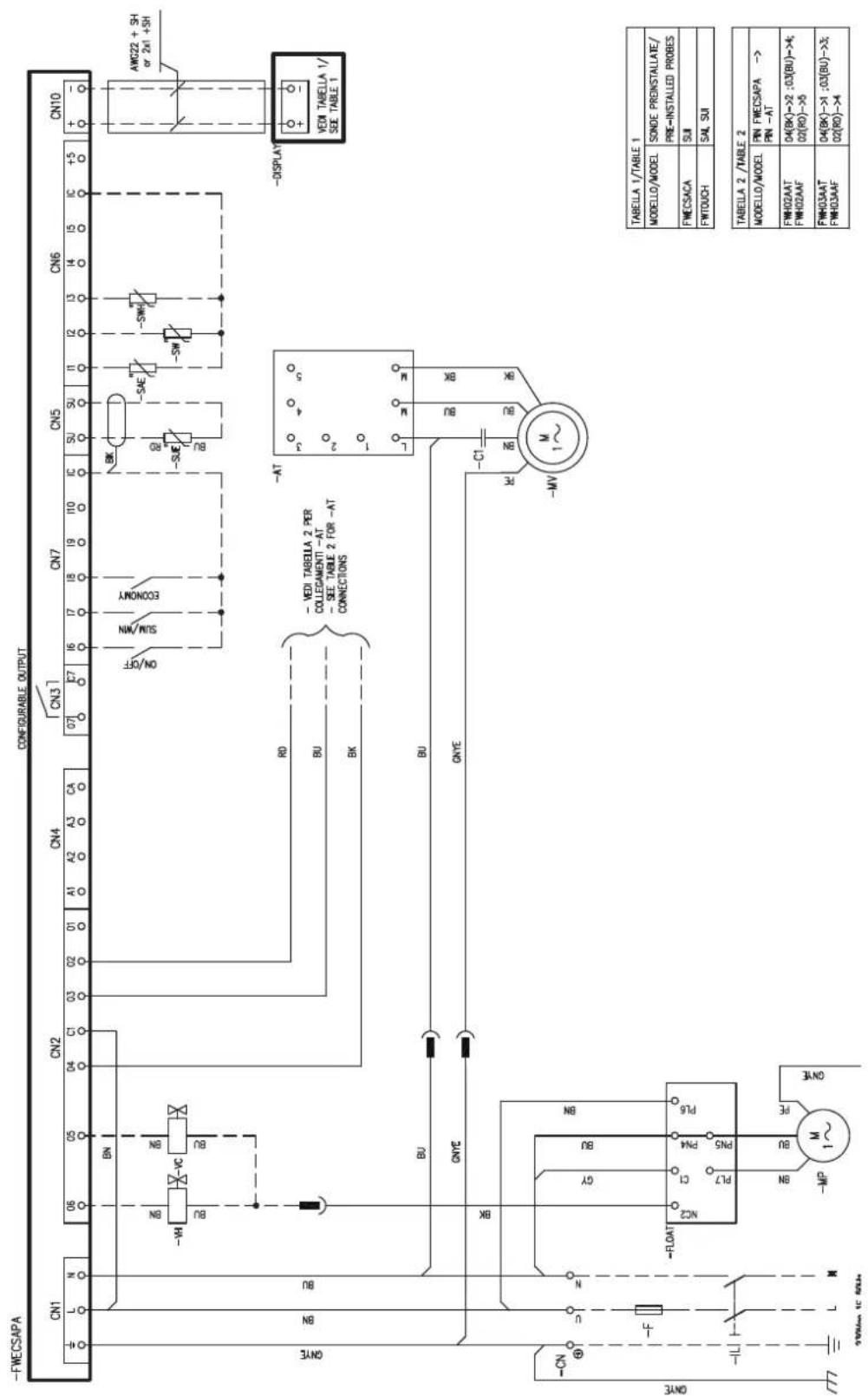
» Schema elettrico FWECSA per modelli FWH-A 04 3 velocità + valvola ON/OFF / FWECSA 3 speed wiring diagram for models FWH-A 04 + ON/OFF valve / Schéma électrique de FWECSA 3 vitesse FWH-A 04 + vanne ON/OFF / Schaltplan FWECSA für Modelle FWH-A 04 3 Geschwindigkeit + ON/OFF-Ventil / Esquema eléctrico FWECSA para modelos FWH-A 04 3 velocidad + valvula ON/OFF / Elektrické schéma FWECSA pro modely FWH-A 04 3 rychlost + ventil ON/OFF / Shema ožičenja FWECSA za modele FWH-A 04 3 brzine + ventil ON/OFF / Schema electrică FWECSA pentru modelele FWH-A 04 3 viteze + supapă ON/OFF
» 13.27
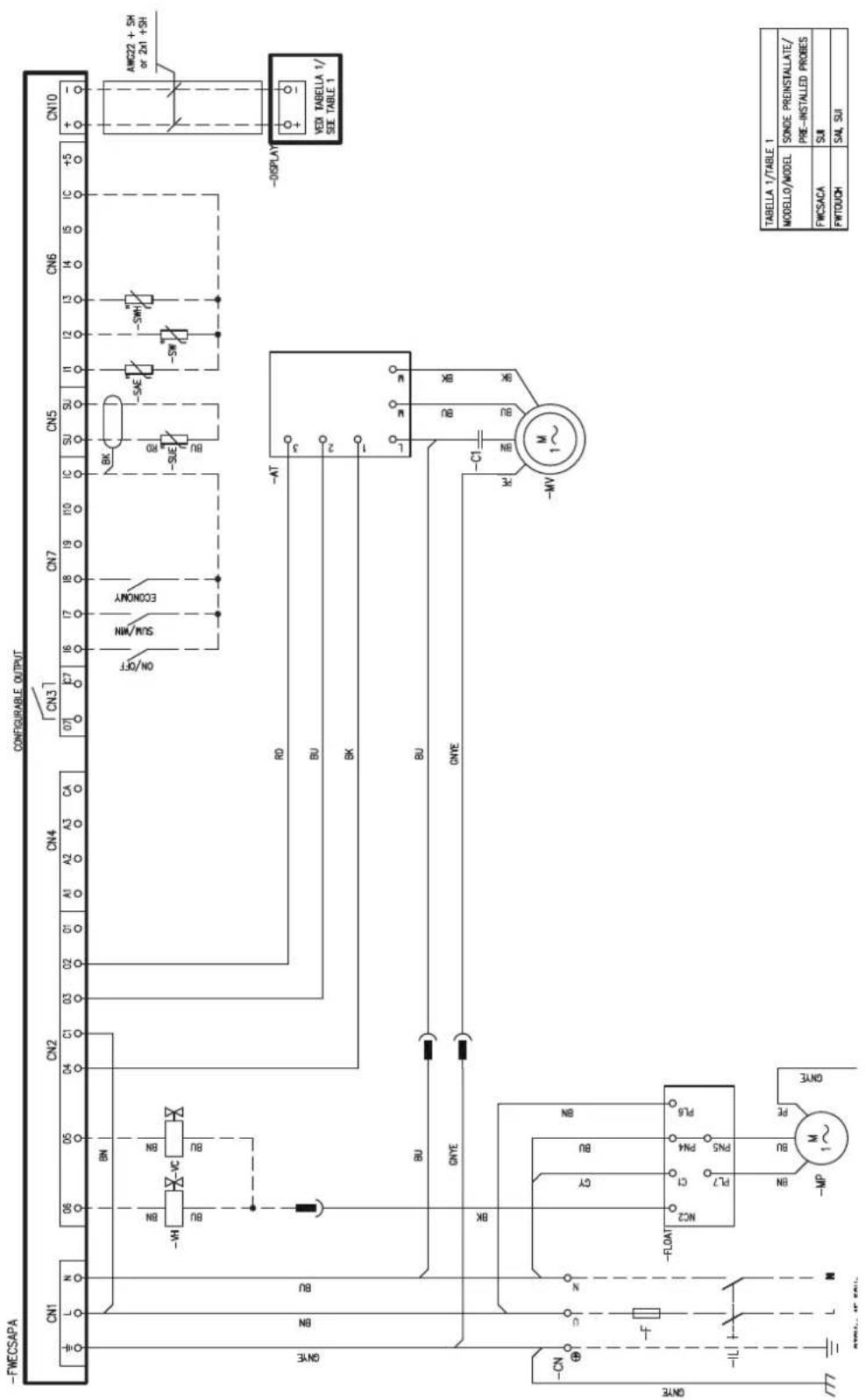
» Schema elettrico FWECSA per modelli FWH-A 06-08 3 velocità + valvola ON/OFF / FWECSA 3 speed wiring diagram for models FWH-A 06-08 + ON/OFF valve / Schéma électrique de FWECSA 3 vitesse FWH-A 06-08 + vanne ON/OFF / Schaltplan FWECSA für Modelle FWH-A 06-08 3 Geschwindigkeit + ON/OFF-Ventil / Esquema eléctrico FWECSA para modelos FWH-A 06-08 3 velocidad + valvula ON/OFF / Elektrické schéma FWECSA pro modely FWH-A 06-08 3 rychlost + ventil ON/OFF / Shema ožičenja FWECSA za modele FWH-A 06-08 3 brzine + ventil ON/OFF / Schema de circuit FWECSA pentru FWH-A 06-08 3 viteze + supapă ON/OFF
» 13.28
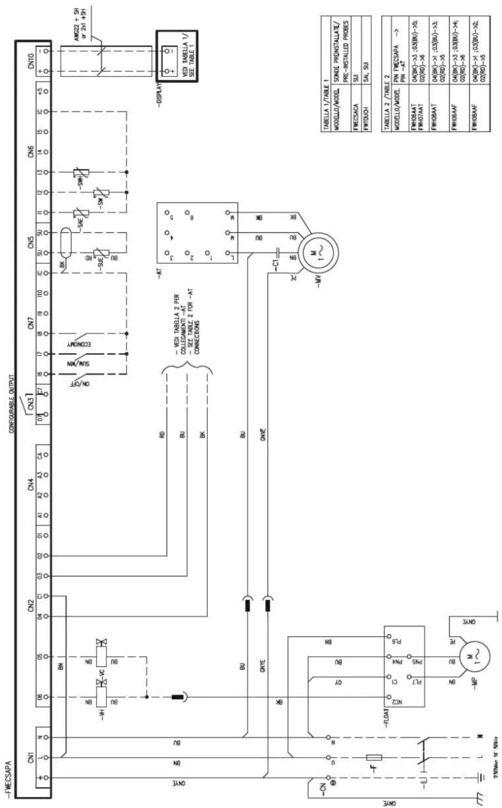
» Schema elettrico FWECSA per modelli FWH-A 02-03 3 velocità + valvola modulante / FWECSA 3 speed wiring diagram for models FWH-A 02-03 + modulating valve / Schéma électrique de FWECSA 3 vitesse FWH-A 02-03 + vanne modulant / Schaltplan FWECSA für Modelle FWH-A 02-03 3 Geschwindigkeit + Modulierende-Ventil / Esquema eléctrico FWECSA para modelos FWH-A 02-03 3 velocidad + valvula modulante / Elektrické schéma FWECSA pro modely FWH-A 02-03 3 rychlost + modulární ventil / Shema ožičenja FWECSA za modele FWH-A 02-03 3 brzine + modulirajući ventil / Schema de circuit FWECSA pentru modelele FWH-A 02-03 3 viteze + supapă modulantă
» 13.29
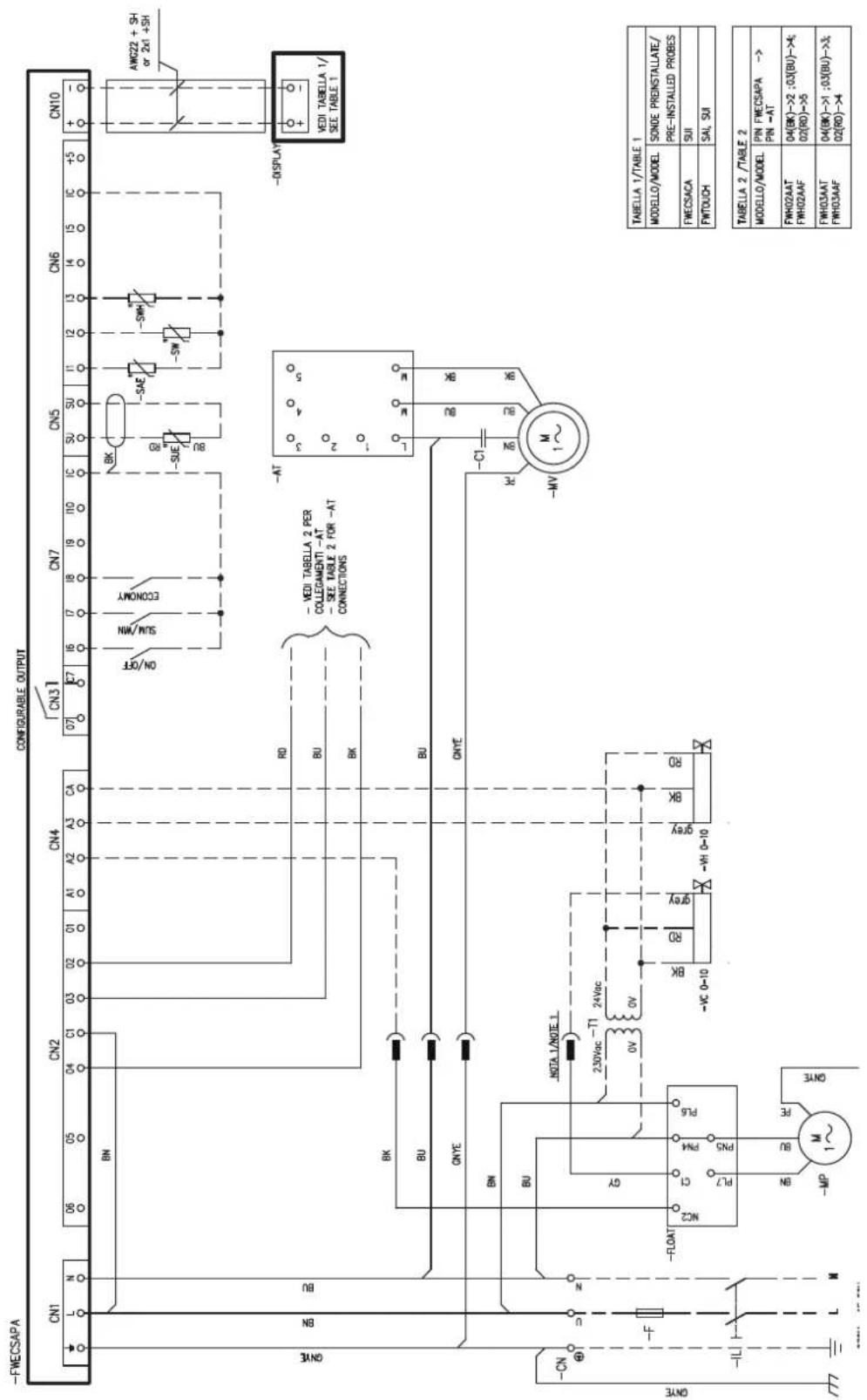
» Schema elettrico FWECSA per modelli FWH-A 04 3 velocità + valvola modulante / FWECSA 3 speed wiring diagram for models FWH-A 04 + modulating valve / Schéma électrique de FWECSA 3 vitesse FWH-A 04 + vanne modulant / Schaltplan FWECSA für Modelle FWH-A 04 3 Geschwindigkeit + Modulierende-Ventil / Esquema eléctrico FWECSA para modelos FWH-A 04 3 velocidad + valvula modulante / Elektrické schéma FWECSA pro modely FWH-A 04 3 rychlost + modulární ventil / Shema ožičenja FWECSA za modele FWH-A 04 3 brzine + modulirajući ventil / Schema electrică FWECSA pentru modelele FWH-A 04 3 viteze + supapă modulantă
» 13.30
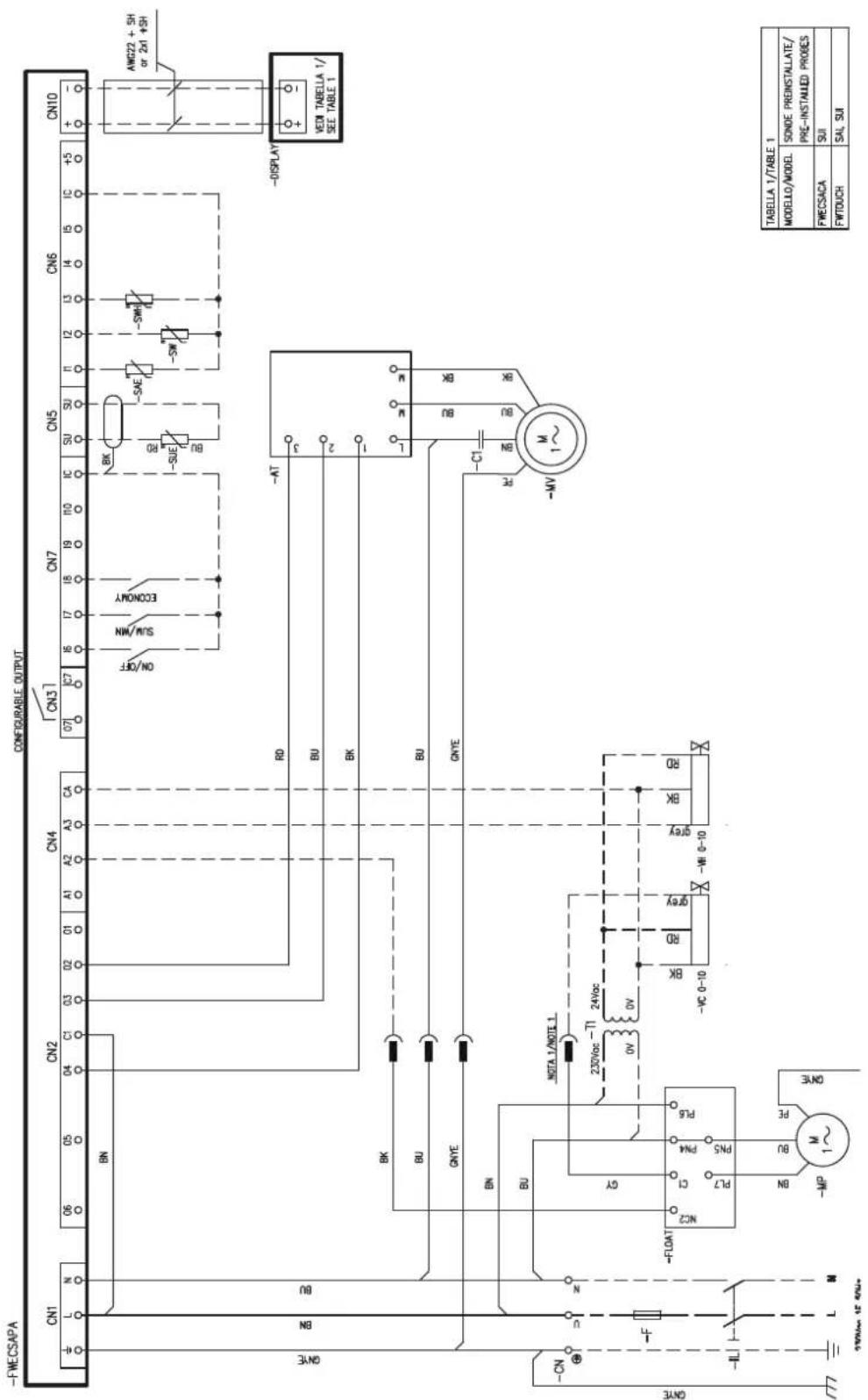
» Schema elettrico FWECSA per modelli FWH-A 06-08 3 velocità + valvola modulante / FWECSA 3 speed wiring diagram for models FWH-A 06-08 + modulating valve / Schéma électrique de FWECSA 3 vitesse FWH-A 06-08 + vanne modulant / Schaltplan FWECSA für Modelle FWH-A 06-08 3 Geschwindigkeit + Modulierende-Ventil / Esquema eléctrico FWECSA para modelos FWH-A 06-08 3 velocidad + valvula modulante / Elektrické schéma FWECSA pro modely FWH-A 06-08 3 rychlost + modulární ventil / Shema ožičenja FWECSA za modele FWH-A 06-08 3 brzine + modulirajući ventil / Schema de circuit FWECSA pentru modelele FWH-A 06-08 3 viteze + supapă modulantă
» 13.31
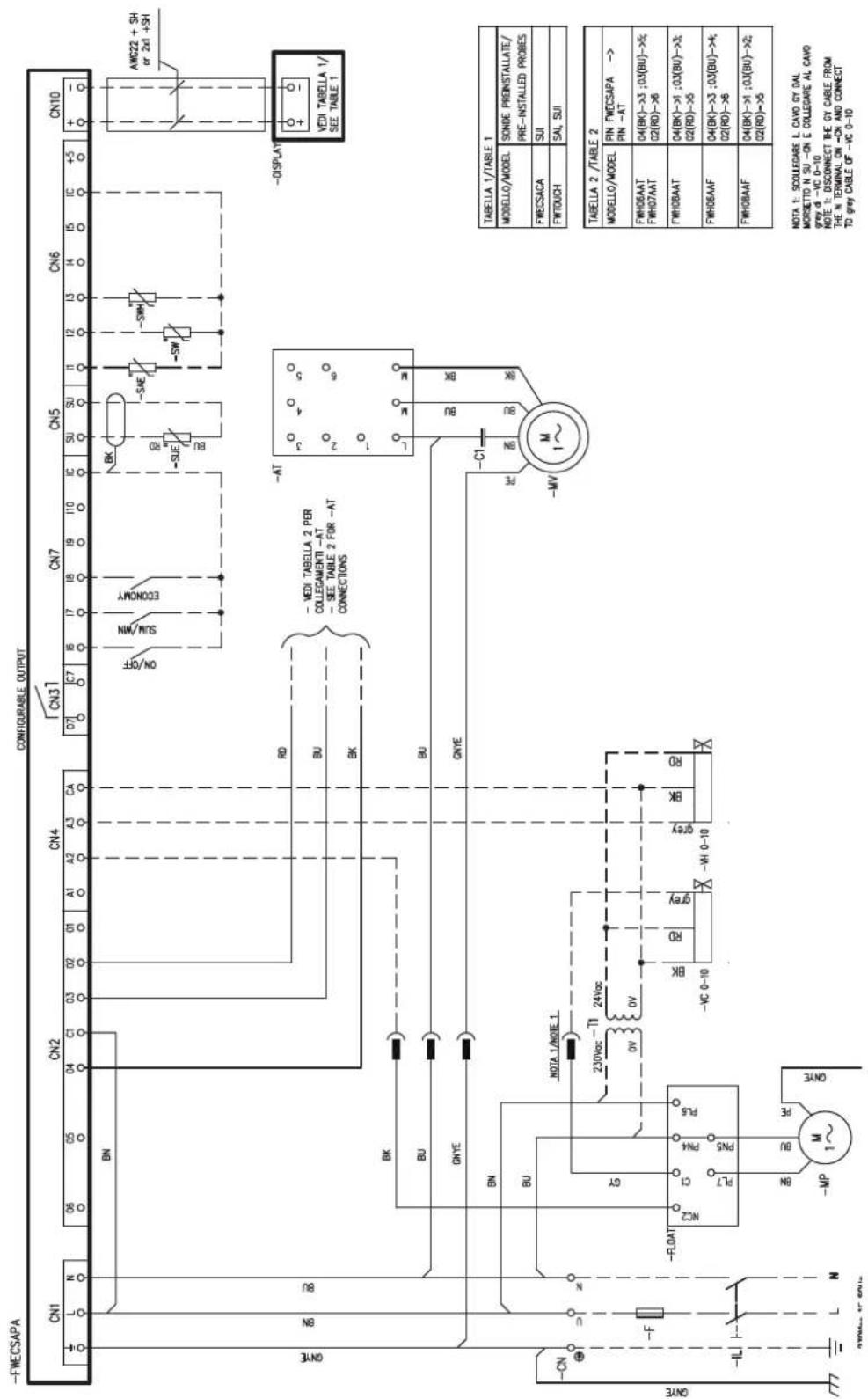
» Schema elettrico FWECSAP per modelli FWH-A 02-03 3 velocità + valvola ON/OFF / FWECSAP 3 speed wiring diagram for models FWH-A 02-03 + ON/OFF valve / Schéma électrique de FWECSAP 3 vitesse FWH-A 02-03 + vanne ON/OFF / Schaltplan FWECSAP für Modelle FWH-A 02-03 3 Geschwindigkeit + ON/OFF-Ventil / Esquema eléctrico FWECSAP para modelos FWH-A 02-03 3 velocidad + valvula ON/OFF / Elektrické schéma FWECSAP pro modely FWH-A 02-03 3 rychlost + ventil ON/OFF / Shema ožičenja FWECSAP za modele FWH-A 02-03 3 brzine + ventil ON/OFF / Schema de circuit FWECSAP pentru modele FWH-A 02-03 3 viteze + supapă ON/OFF
» 13.32
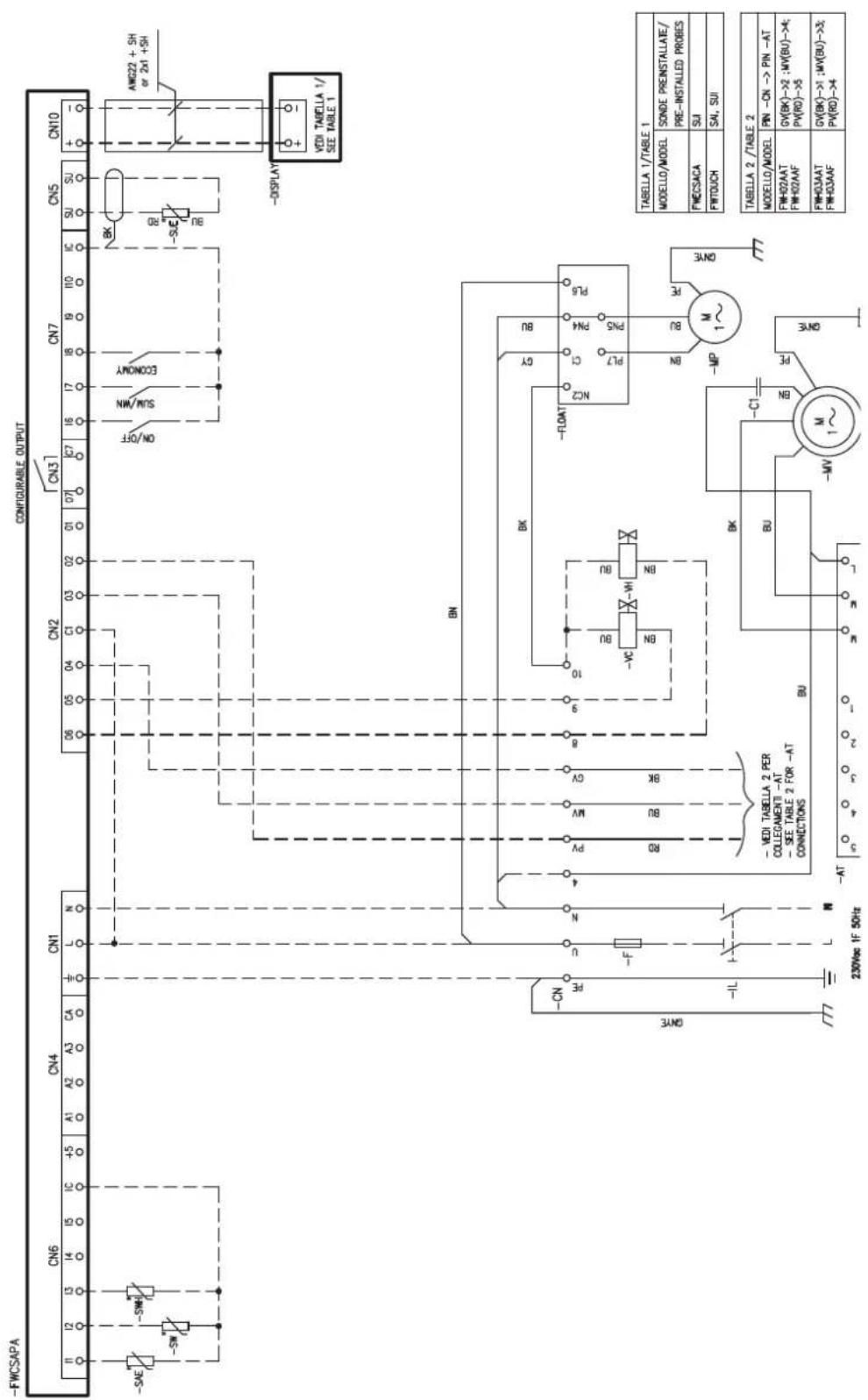
» Schema elettrico FWECSAP per modelli FWH-A 04 3 velocità + valvola ON/OFF / FWECSAP 3 speed wiring diagram for models FWH-A 04 + ON/OFF valve / Schéma électrique FWECSAP 3 vitesse FWH-A 04 + vanne ON/OFF / Schaltplan FWECSAP für Modelle FWH-A 04 3 Geschwindigkeit + ON/OFF-Ventil / Esquema eléctrico FWECSAP para modelos FWH-A 04 + valvula ON/OFF / Elektrické schéma FWECSAP pro modely FWH-A 04 3 nychlost + ventil ON/OFF / Shema ožičenja FWECSAP za modele FWH-A 04 3 brzine + ventil ON/OFF / Schema de circuit FWECSAP pentru modelele FWH-A 04 3 viteze + supapă ON/OFF
» 13.33
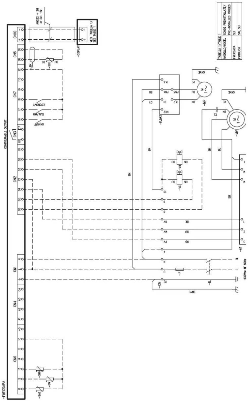
» Schema elettrico FWECSAP per modelli FWH-A 06-08 3 velocità + valvola ON/OFF / FWECSAP 3 speed wiring diagram for models FWH-A 06-08 + ON/OFF valve / Schéma électrique de FWECSAP 3 vitesse FWH-A 06-08 + vanne ON/OFF / Schaltplan FWECSAP für Modelle FWH-A 06-08 3 Geschwindigkeit + ON/OFF-Ventil / Esquema eléctrico FWECSAP para modelos FWH-A 06-08 3 velocidad + valvula ON/OFF / Elektrické schéma FWECSAP pro modely FWH-A 06-08 3 rychlost + ventil ON/OFF / Shema ožičenja FWECSAP za modele FWH-A 06-08 3 brzine + ventil ON/OFF / Schema de circuit FWECSAP pentru modele FWH-A 06-08 3 viteze + supapă ON/OFF
» 13.34
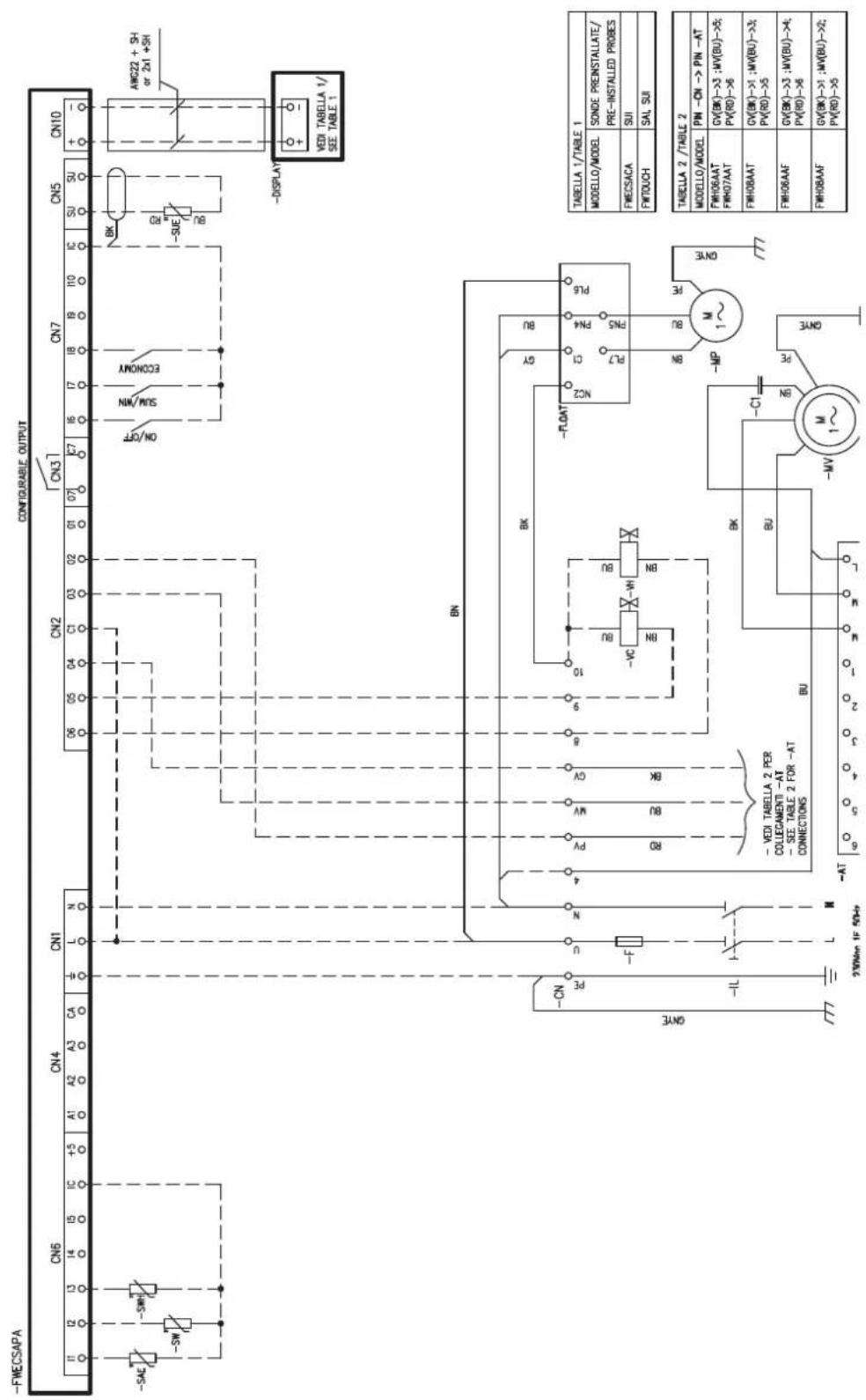
» Schema elettrico FWECSAP per modelli FWH-A 02-03 3 velocità + valvola modulante / FWECSAP 3 speed wiring diagram for models FWH-A 02-03 + modulating valve / Schéma électrique de FWECSAP 3 vitesse FWH-A 02-03 + vanne modulant / Schaltplan FWECSAP für Modelle FWH-A 02-03 3 Geschwindigkeit + Modulierende-Ventil / Esquema eléctrico FWECSAP para modelos FWH-A 02-03 3 velocidad + valvula modulante / Elektrické schéma FWECSAP pro modely FWH-A 02-03 3 rychlost + modulární ventil / Shema ožičenja FWECSAP za modele FWH-A 02-03 3 brzine + modulirajući ventil / Schema de circuit FWECSAP pentru modelele FWH-A 02-03 3 viteze + supapă modulantă
» 13.35
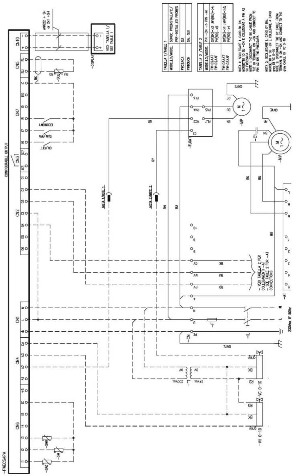
» Schema elettrico FWECSAP per modelli FWH-A 04 3 velocità + valvola modulante / FWECSAP 3 speed wiring diagram for models FWH-A 04 + modulating valve / Schéma électrique de FWECSAP 3 vitesse FWH-A 04 + vanne modulant / Schaltplan FWECSAP für Modelle FWH-A 04 3 Geschwindigkeit + Modulierende-Ventil / Esquema eléctrico FWECSAP para modelos FWH-A 04 3 velocidad + valvula modulante / Elektrické schéma FWECSAP pro modely FWH-A 04 3 rychlost + modulární ventil / Shema ožičenja FWECSAP za modele FWH-A 04 3 brzine + modulirajući ventil / Schema de circuit FWECSAP pentru modele FWH-A 04 3 viteze + supapă modulantă
» 13.36
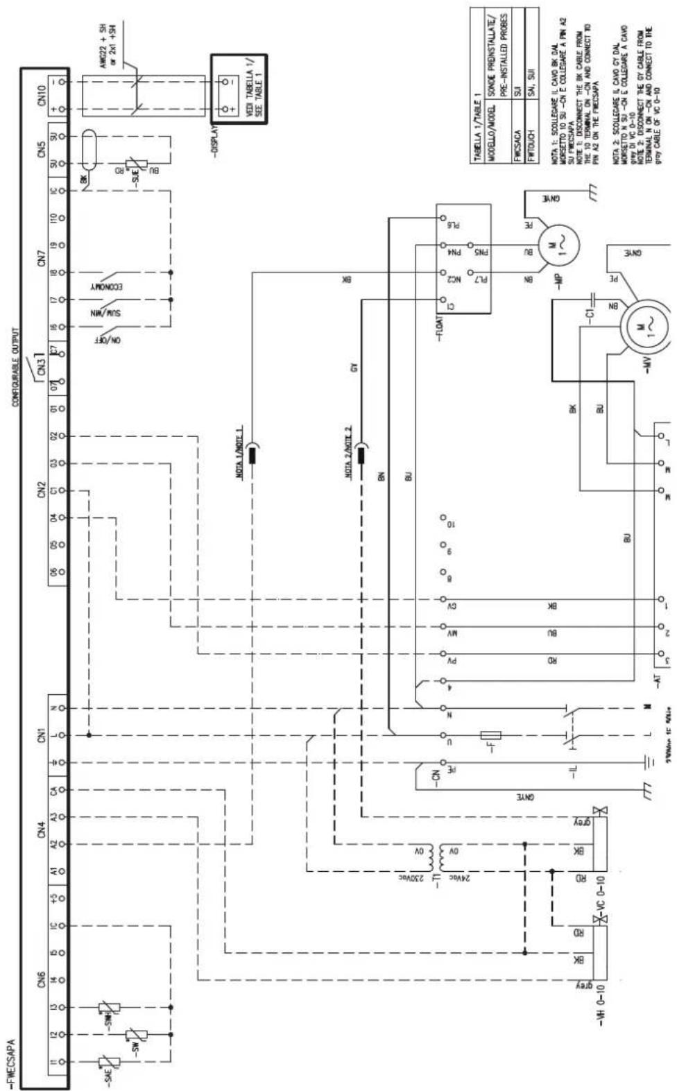
» Schema elettrico FWECSAP per modelli FWH-A 06-08 3 velocità + valvola modulante / FWECSAP 3 speed wiring diagram for models FWH-A 06-08 + modulating valve / Schéma électrique de FWECSAP 3 vitesse FWH-A 06-08 + vanne modulant / Schaltplan FWECSAP für Modelle FWH-A 06-08 3 Geschwindigkeit + Modulierende-Ventil / Esquema eléctrico FWECSAP para modelos FWH-A 06-08 3 velocidad + valvula modulante / Elektrické schéma FWECSAP pro modely FWH-A 06-08 3 rychlost + modulární ventil / Shema ožičenja FWECSAP za modele FWH-A 06-08 3 brzine + modulirajući ventil / Schema de circuit FWECSAP pentru modelele FWH-A 06-08 3 viteze + supapă modulantă
» 13.37
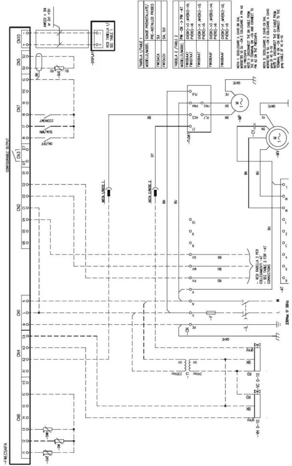
» Kit valvola 2 vie - 2 tubi FWH-A 02-03-04 / 2-way valve kit - 2 pipes, FWH-A 02-03-04 / Kit vanne 2 voies - 2 tuyaux FWH-A 02-03-04 / 2-Wege-Ventilsatz - 2 Rohre FWH-A 02-03-04 / Kit de válvula de 2 vias - 2 tubos FWH-A 02-03-04 / Sada dvoucestného ventilu - 2 trubky FWH-A 02-03-04 / Komplet dvosmjernih ventila - 2 cijevi FWH-A 02-03-04 / Kit de supapă cu 2 căi - 2 tevi FWH-A 02-03-04
»13.38
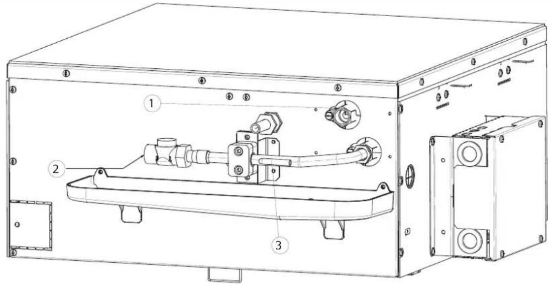
1)
Uscita acqua / Water outlet / Sortie d'eau / Auslass wasser / Salida de agua / Odvod vody / Iziaz vode / leşire apă 2)
Ingresso acqua / Water inlet / Lentric d'eau / Einlass wasser / Entrada de agua / Přivod vody / Ulaž vode / Intrae apá 3)
1)
Uscita acqua / Water outlet / Sortie d'eau / Auslass wasser / Salida de agua / Odvod vody / Izlaz vode / leşire apă 2)
Ingresso acqua / Water inlet / Entrée d'eau / Einlass wasser / Entrada de agua / Privod vody / Uiaz vode / Intrare apà 3)
1)
Uscita acqua fredda / Cold water outlet / Sortie d'eau froide / Kaltwasserauslass / Salida de agua fria / Odvod studené vody / Izlaz nladne vode / leşire apä rece
2)
Ingresso acqua fredda / Cold water inlet / Entrée d'eau froide / Kaltwassereinlass / Entrada de agua fria / Přivod studené vody / Ullaz hladne vode / Intrare apá rece
3)
Uscita acqua calda / Hot water pellet / Sortie d'eau chaude / Warmewasserauslass / Salida de agua caliente / Odvod toplé vody / Izlaz tople vode / Ilesire apà calda
4)
Ingresso acqua calda / Hot water inlet / Entrée d'eau chaude / Warmwassereinlass / Entrada de agua caliente / Přivod teplé vody / Uíaz tople vode / Intraie apa calda
5)
1)
Uscita acqua fredda / Cold water outlet / Sortie d'eau froide / Kaltwasserauslass / Salida de aqua fria / Odvod studené vody / Izlaz nladne vode / leşire apă rece
2)
ingresso acqua fredda / Cold water inlet / Entrée d'eau froide / Kaltwassereinlass / Entrada de aqua fria / Přivod studené vody / Ulaž hladne vode / Intrare apá rece
3)
Uscita acqua caida / Hot water outlet / Sortie d'eau chaude / Warmwasserauslass / Salida de agua caliente / Odvod teplé vody / Izlaz tople vode / lesire apà caldã
4)
ingresso acqua calda / Hot water inlet / Entrée d'eau chaude / Warmwassereinlass / Entrada de aqua caliente / Přivod teplé vody / Ulaz tople vode / Intrare apá caldă
5)
Porta sonda / Sensor holder / Port sonde / Wasserfühlerhalterung / Portasonda / Držak sondy / Nosač sonde / Suport sondá
NOTA: G-Iattuatori non sono rappresentati. / NOTI: The actuators are not shown. / NOTI: les actionneurs ne sont pas représentés. / HIWEIS: Die Stellantinebe sind nicht abgebildet. / NOTA: Los actuadores no están representados. / POTKÁMKA: Ákční Oleny nepsoz zastoupeny. / OIL JESKA: Aktuatori nisu prikazami. / NOTA: Actuatoarele nu sunt reprzentato.
» Kit valvola 3 vie - 4 tubi FWH-A 06-08 / 3-way valve kit - 4 pipes, FWH-A 06-08 / Kit vanne 3 voies - 4 tuyaux FWH-A 06-08 / 3-Wege-Ventilsatz - 4 Rohre FWH-A 06-08 / Kit de válvula de 3 vías - 4 tubos FWH-A 06-08 / Sada trojcestného ventilu - 4 trubky FWH-A 06-08 / Komplet trosmjernih ventila - 4 cíjevi FWH-A 06-08 / Kit supapă cu 3 căi - 4 tevi FWH-A 06-08
» 13.42
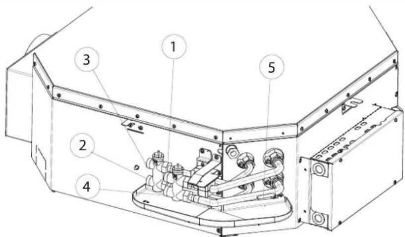
1)
Uscita acqua fredda / Cold water outlet / Sortie d'eau froide / Kaltwasserauslass / Salida de aqua fria / Odvod studené vody / Iziaz hladne vode / leşire apä rece
2)
Ingresso acqua fredda / Cold water inlet / Entrée d'eau froide / Kaltwassereinlass / Entrada de agua fria / Pifvod studené vocy / Ulaz hladne vode / Intrare apà rece
3)
Uscita acqua calda / Hot water outlet / Sortie d'eau chaude / Warmwasserauslass / Salida de agua caliente / Odvod teplè vody / Izlaz tople vode / Iesire apà caldà
4)
Ingresso acqua calca / Hot water inlet / Entrée d'eau chaude / Warmwassereinlass / Entrada de aqua caliente / Pflvod teplé vody / Uiaz tople vode / Intrare apà ca dã
5)
1)
Jscita acqua / Water outlet / Sortie d'eau / Auslass wasser / Salida de aqua / Odvod vody / Izlaz vode / leşire apä
2)
Ingresso acqua /Water inlet / Entrée d'eau / Einlass wasser / Entrada de agua / Privod vody / Uiaz vode / Intrare apà
3)
1)
Uscita acqua fredda / Cold water outlet / Sortie d'eau froide / Kaltwasserauslass / Salida de agua fria / Odvod studené vody / Iziaz hladne vode / leşire apã rece.
2)
Ingresso acqua frecuta / Cold water inlet / Entrée d'eau froide / Kaltwassere nlass / Entrada de agua fria / Pfixol studené vody / Ulaz hladne vode / Intrare apà rece
3)
Uscita acqua calda / Hot water outlet / Sortie d'eau chaude / Warmwasserauslass / Salida de agua calliente / Odvod teplè vody / Izlaz tople vode / leşire apà caldă
4)
Ingresso acqua calda / Hot water inlet / Entrée d'eau chaude / Warmwassereinlass / Entrada de agua caliente / Přívod teplé vody / U'az tople vode / Intrare apà caldā
5)
1)
Uscita acqua / Water outlet / Sortie d'eau / Auslass wasser / Salida de agua / Odvod vody / Izlaz voce / Lesire apà
2)
Ingresso acqua /Water inlet / Entrée d'eau / Einlass wasser / Entrada de agua / Pfivod vody / Uaz voce / Intrare apà
3)
1)
Uscita acqua / Water outlet / Sortie d'eau / Auslass wasser / Salida de agua / Odvod vody / Izlaz vode / leşire apà
2)
ingresso acqua / Water inlet / Entrée d'eau / Einlass wasser / Entrada de agua / Pivod vody / Ullay vode / Intrare apà
» Kit valvola E2C2PIC/PRP; E4C2PIC/PRP 2 vie - 4 tubi FWH-A 02-03-04 / 2-way E2C2PIC/PRP; E4C2PIC/PRP valve kit - 4 pipes, FWH-A 02-03-04 / Kit vanne E2C2PIC/PRP; E4C2PIC/PRP 2 voies - 4 tuyaux FWH-A 02-03-04 / 2-Wege-Ventilsatz E2C2PIC/PRP; E4C2PIC/PRP - 4 Rohre FWH-A 02-03-04 / Kit de válvula E2C2PIC/PRP; E4C2PIC/PRP de 2 vías - 4 tubos FWH-A 02-03-04 / Sada ventilu E2C2PIC/PRP; E4C2PIC/PRP dvoucestný - 4 trubky FWH-A 02-03-04 / Komplet ventila E2C2PIC/PRP; E4C2PIC/PRP dvosmjerni - 4 cijevi FWH-A 02-03-04 / Kit de supape E2C2PIC/PRP; E4C2PIC/PRP cu 2 căi - 4 tevi FWH-A 02-03-04
» 13.47
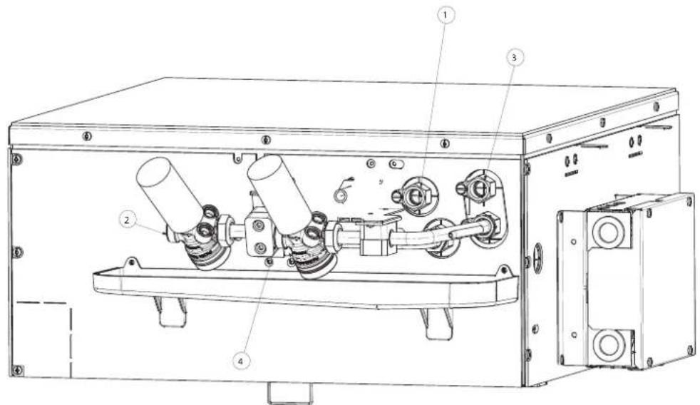
1)
Uscita acqua fredda / Cold water outlet / Sortie d'eau froide / Kaltwasserauslass / Salida de agua fria / Odvod studenté vody / Iziaz h'adne vode / Iejire apà rece
2)
Ingresso acqua fredda / Cold water inlet / Entrée d'eau fluide / Kaltwassereinlass / Entrada de agua fria / Přivod studené vody / Ulaz hladne vode / Intrare apá rece
3)
Uscita acqua calda / Hot water outlet, / Sortie d'eau chaude / Warmwasserauslass / Salida de agua caliente / Odvod teplé vody / izlaz tople vode / lésire apà caldã
4)
Ingresso acqua calda / Hot water inlet / Entrée d'eau chaude / Warmwassereinlass / Entrada de agua caliente / Přívod toplé vody / Ullaz tople vode / Intrare apă caldă
» Kit valvola E2C2PIC/PRP; E4C2PIC/PRP 2 vie - 2 tubi FWH-A 06-07-08 / 2-way E2C2PIC/PRP; E4C2PIC/PRP valve kit - 2 pipes, FWH-A 06-07-08 / Kit vanne E2C2PIC/PRP; E4C2PIC/PRP 2 voies - 2 tuyaux FWH-A 06-07-08 / 2-Wege-Ventilsatz E2C2PIC/PRP; E4C2PIC/PRP - 2 Rohre FWH-A 06-07-08 / Kit de válvula E2C2PIC/PRP; E4C2PIC/PRP de 2 vías - 2 tubos FWH-A 06-07-08 / Sada ventilu E2C2PIC/PRP; E4C2PIC/PRP dvoucestný - 2 trubky FWH-A 06-07-08 / Komplet ventila E2C2PIC/PRP; E4C2PIC/PRP dvo-smjerni - 2 cijevi FWH-A 06-07-08 / Kit de supape E2C2PIC/PRP; E4C2PIC/PRP cu 2 cǎi - 2 tevi FWH-A 06-07-08
» 13.48
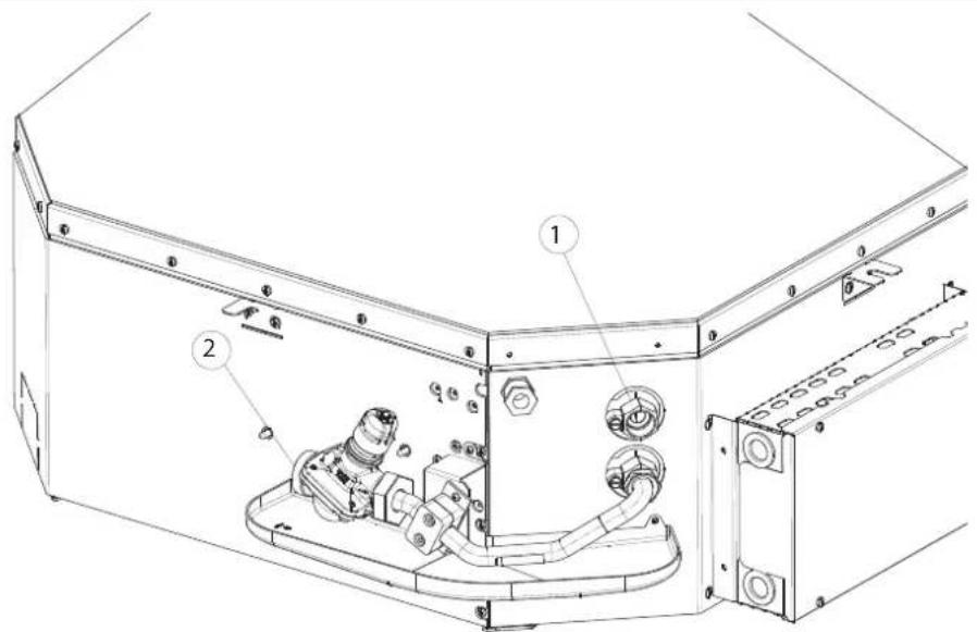
1)
Uscita acqua / Water outlet / Sortie d'eau / Auslass wasser / Salida de agua / Odvod vody / Izlaz voie / leşire apà
2)
ingresso acqua / Water inlet / Entrée d'eau / Einlass wasser / Entrada de agua / Privod vody / Ulaz vode / Intrare apà
» Kit valvola E2C2PIC/PRP; E4C2PIC/PRP 2 vie - 4 tubi FWH-A 06-08 / 2-way valve kit E2C2PIC/PRP; E4C2PIC/PRP - 4 pipes, FWH-A 06-08 / Kit vanne E2C2PIC/PRP; E4C2PIC/PRP 2 voies - 4 tuyaux FWH-A 06-08 / E2C2PIC/PRP; E4C2PIC/PRP 2-Wege-Ventilsatz - 4 Rohre FWH-A 06-08 / Kit de válvula E2C2PIC/PRP; E4C2PIC/PRP de 2 vías - 4 tubos FWH-A 06-08 / Sada ventilu E2C2PIC/PRP; E4C2PIC/PRP dvoucestný - 4 trubky FWH-A 06-08 / Komplet ventila E2C2PIC/PRP; E4C2PIC/PRP dvosmjerni - 4 cijevi FWH-A 06-08 / Kit de supape E2C2PIC/PRP; E4C2PIC/PRP cu 2 căi - 4 țevi FWH-A 06-08
» 13.49
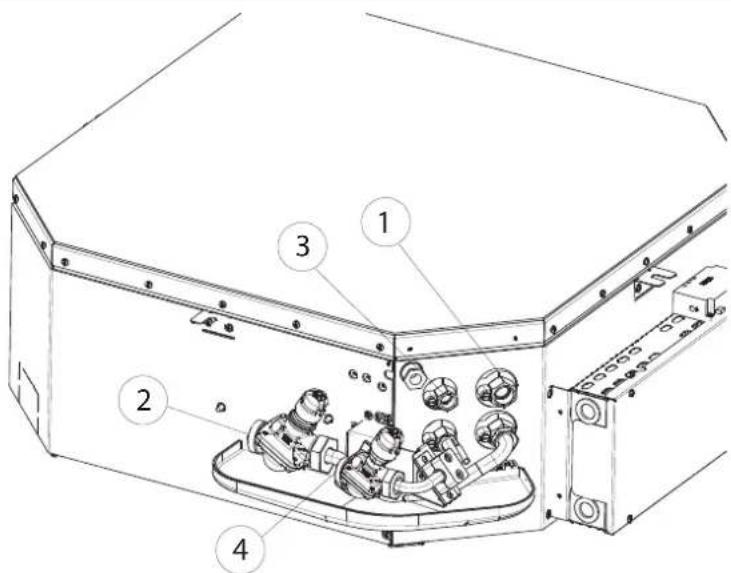
1)
Uscita acqua fredda / Cold water outlet / Sortie d'eau froide / Kaltwasserauslass / Salida de agua fria / Odvod studené vody / Iziaz nladne vode / leşire apä rece
2)
ingresso acqua fredda / Cold water inlet / Entrée d'eau froide / Kaltwassereinlass / Entrada de agua fria / Privod studené vody / Ullaz hladne vode / Intrare apà rece
3)
Uscrita acqua calda / Hot water outlet / Sortie d'eau chaude / Warmwasseraus ass / Salida de agua caliente / Odvod teplé vody / Izlaz tople vode / lesire apà caïdä
4)
Ingresso acqua calca / Hot water inlet / Entrée d'eau chaude / Warmwassereinlass / Entrada de agua caliente / Privod teplé vody / U az tople vode / Intrare apà calda