
WEPBA 17-125 Quick RT - Sander METABO - Free user manual and instructions
Find the device manual for free WEPBA 17-125 Quick RT METABO in PDF.

| Product type | Angle grinder / Angle sander |
| Brand | Metabo |
| Model | WEPBA 17-125 Quick RT |
| Max. disc diameter | 125 mm |
| Power consumption | 1700 W |
| No-load speed (adjustable) | 2800 - 11000 rpm |
| Power supply | 230 V ~ 50 Hz |
| Spindle thread | M14 |
| Spindle length | 22.2 mm |
| Weight (without cable) | 2.4 kg |
| Protection class | II (double insulation) |
| Disc fixing system | Metabo Quick (M-Quick) |
| Variable speed | Yes (wheel) |
| Safety clutch | Metabo S-automatic |
| Restart protection | Yes (electronic indicator) |
| Switch | Paddle with dead man's function (RT) |
| Additional handle | With vibration damping |
| Protection guard | Tool-free adjustable |
| Cable length | 4 m |
| Sound pressure level | Up to 92 dB(A) |
| Sound power level | Up to 103 dB(A) |
| Vibrations (grinding) | 9.4 m/s² |
Frequently Asked Questions - WEPBA 17-125 Quick RT METABO
User questions about WEPBA 17-125 Quick RT METABO
0 question about this device. Answer the ones you know or ask your own.
Ask a new question about this device
Download the instructions for your Sander in PDF format for free! Find your manual WEPBA 17-125 Quick RT - METABO and take your electronic device back in hand. On this page are published all the documents necessary for the use of your device. WEPBA 17-125 Quick RT by METABO.
USER MANUAL WEPBA 17-125 Quick RT METABO
WEPBA 17-125 Quick DS
WEPBA 17-125 Quick RT
WEPBA 17-125 Quick RT DS
WEPBA 17-150 Quick
WEPBA 17-150 Quick RT
WEPBA 17-150 Quick RT DS
WEA 19-180 Quick RT
natural_image
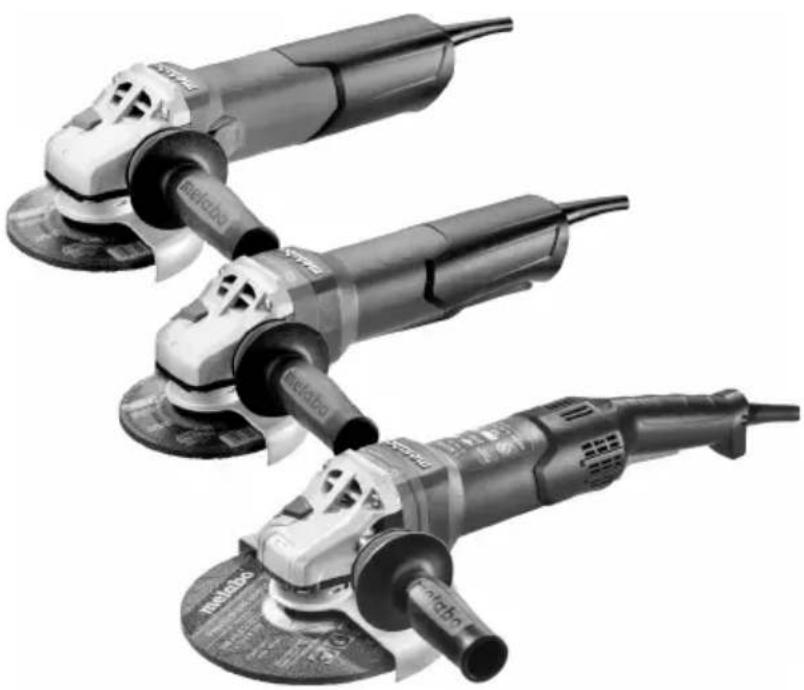
Three electric motor washers with visible brand logos, arranged diagonally (no text or symbols on the machines themselves)WEPBA 19-125 Q DS M-Brush
WEPBA 19-150 Q DS M-Brush
WEPBA 19-180 Quick RT
WEA 19-125 Q M-BRUSH IK

Chief Tecnology Officer Koki Holdings Co., Ltd.
*4) Metabowerke GmbH - Metabo-Ällee 1 - 72622 Nuertingen, Germany
 | WEVB 17-125 Quick*1) 00522.. | WEPBA 17-150 Quick*1) 00552.. | WEA 19-180 Quick RT*1) 01095.. | WEPBA 17-125 Quick RT*1) 01097.. | WEPBA 17-125 Quick RT DS*1) 00605.. | WEPBA 17-150 Quick RT*1) 01098.. | WEPBA 17-150 Quick RT DS*1) 00606.. | WEPBA 19-125 Q DSM-Brush*1) 13114.. | WEPBA 19-150 Q DSM-Brush*1) 13117.. | WEPBA 19-180 Quick RT*1) 01099.. | WEA 19-125 Q M-BRUSH IK*1) 21075.. | |
| M-Quick - | √ | √ √ | √ | √ √ | √ | √ | √ | |||||
| Electronic - | TC TC | TC TC TC | TC TC TC | TC TC | ||||||||
| ∅ mm (in) | 125 (5) | 50 (6) 180 | (7) 125 | (5) 150 (6) | 125 (5) | 150 (6) | 180 | (7) 125 (5) | ||||
| tmax1; tmax2; tmax3; tmax4 | mm (in) | 10:7,1;7,1;15 3/8;9/32;9/32;f9/32 | ||||||||||
| MD M / I | -/mm(in) | M 14/15 19/32 | ||||||||||
| n | min-1(rpm) | 11000 | 0000 8200 | 11000 | 0000 11000 | 9600 8200 | 1 | 1000 | ||||
| nV | min-1(rpm) | 2800-11000 | - | - | - | - | - | - | - | - | - | |
| P1 | W | 1700 | 1700 | 1900 | 1750 | 1750 | 1900 | 1900 | 1900(110V=1700) | 1900 | ||
| P2 | W | 1040 | 1040 | 1240 | 1070 | 1070 | 1220 | 1220 | 1240 | 1220 | ||
| m kg (lbs) | 2,7(6.0) | 2,8 (6.2) | 2,7 (6.0) | 2,7 (5.0) | 2,8 (6.2) | 2,7(6.0) | 2,8 (6.2) | 2,9 (6.4) | 2,5 (5.5) | |||
| ah,SG/Kh,SG | m/s2 | 6,0/1,5 | 4,5/1,5 | 4,9/1,5 | 6,1/1,5 | 6,0/1,5 | 4,0/1,5 | 4,5/1,5 | 4,9/1,5 | 4,0/1,5 | ||
| ah,DS/Kh,DS | m/s2 | 3,6/1,5 | 4,2/1,5 | 4,0/1,5 | 4,4/1,5 | 4,9/1,5 | 3,0/1,5 | 4,2/1,5 | 5,0/1,5 | 4,0/1,5 | ||
| ah,P/Kh,P | m/s2 | - | - | - | - | - | - | - | - | - | ||
| LpA/KpA | dB(A) | 96/3 | 96/3 | 97/3 | 95/3 | 95/3 | 96/3 | 96/3 | 95/3 | 96/3 | ||
| LWA/KWA | dB(A) | 104/3 | 104/3 | 105/3 | 103/3 | 103/3 | 104/3 | 104/3 | 103/3 | 104/3 | ||
bar
| Category | Value | |---|---| | 1 | 1.1 | | 2 | 1.2 | | 2 | 1.3 | | 2 | 2.1 | | 2 | 2.2 | | 2 | 2.3 | | 2 | 2.4 | | 3 | 3.1 | | 4 | 4.1 | | 5 | 4.2 | | 6 | 6.1 | TYPE B/C D E A/C A A/F A/C - A/B/C - B/C -
natural_image
Two identical black industrial vacuum cleaner units with coiled tubing, shown side by side (no visible text or symbols)*1 = 100mm (4") 630346000
=115\ mm\ (41/2)630351000
= 125 mm (5 ) 630352000
= 150 mm (6") 63035300
= 180 mm (7 ) 630383000
*2 WEA 19-180 Quick RT,
WEPBA 19-180 Quick RT: 339204780
*3 = 115mm 125mm 150mm
→ 623276000 (∅=80 mm)
max=180mm:
→ 623140000 (∅=110 mm)
*4 ∅max= 125 mm:
→ GED 125: 626732000
*5 max = 125mm :
→ CED 125: 626730000
→ CED 125 Plus: 626731000
6.30441 (WP..13 - WP..19)
6.30792 (WPB 13-1 - WEP..17-1)⚠️ DS
6.30719 (W... RT)
6.30835 (W.. 9-1 - W.. 11-1...)
6.30709 (W.. 13-1 - WE.. 17-1)

Original instructions
1. Declaration of Conformity
We, being solely responsible: Hereby declare that these angle grinders, identified by type and serial number *1), meet all relevant requirements of directives *2) and standards *3). technical documents for *4) - see Page 4.
For UK only:
UK CA We as manufacturer and authorized person to compile the technical file, see *4) on page 4, hereby declare under sole responsibility that these angle grinders, identified by type and serial number *1) on page 3, fulfill all relevant provisions of following UK Regulations S.I. 2016/1091, S.I. 2008/1597, S.I. 2012/3032 and Designated Standards see *3) on page 4.
2. Specified Use
The angle grinders, when fitted with original Metabo accessories, are suitable for grinding, sanding, abrasive cutting-off operations and wire brushing metal, concrete, stone and similar materials without the use of water.
WEVA 15-125 Quick, WEVA 15-150 Quick is additionally suited for light polishing work. We recommend using our angle polisher for demanding polishing work in continuous operation.
Machines with the designation WEV... are particularly suited for working with wire brushes due to thumbwheel for speed selection.
The user bears sole responsibility for any damage caused by inappropriate use.
Generally accepted accident prevention regulations and the enclosed safety information must be observed.
3. General Safety Instructions

For your own protection and for the protection of your power tool, pay attention to all parts of the text that are marked with this symbol!

WARNING – Read the operating instructions to reduce the risk of injury.

WARNING – Read all safety warnings, instructions, illustrations and
specifications provided with this power tool.
Failure to follow all instructions listed below may result in electric shock, fire and/or serious injury.
Save all warnings and instructions for future reference.
Always include these documents when passing on your power tool.
4. Special Safety Instructions
4.1 Safety Warnings Common for Grinding, Sanding, Wire Brushing, Polishing or Cutting-Off Operations:
a) This power tool is intended to function as a grinder, sander, wire brush, hole cutter or cut-off tool. Read all safety warnings, instructions, illustrations and specifications provided with this power tool. Failure to follow all instructions listed below may result in electric shock, fire and/or serious injury. WEVA 15-125 Quick, WEVA 15-150 Quick may also be used as a polisher.
b) Operations such as polishing are not to be performed with this power tool. Operations for which the power tool was not designed may create a hazard and cause personal injury. (This does not apply to WEVA 15-125 Quick, WEVA 15-150 Quick.)
c) Do not convert this power tool to operate in a way which is not specifically designed and specified by the tool manufacturer. Such a conversion may result in a loss of control and cause serious personal injury.
d) Do not use accessories which are not specifically designed and specified by the tool manufacturer. Just because the accessory can be attached to your power tool, it does not assure safe operation.
e) The rated speed of the accessory must be at least equal to the maximum speed marked on the power tool. Accessories running faster than their rated speed can break and fly apart.
f) The outside diameter and the thickness of your accessory must be within the capacity rating of your power tool. Incorrectly sized accessories cannot be adequately guarded or controlled.
g) The dimensions of the accessory mounting must fit the dimensions of the mounting hardware of the power tool. Accessories that do not match the mounting hardware of the power tool will run out of balance, vibrate excessively and may cause loss of control.
h) Do not use a damaged accessory. Before each use inspect the accessory such as abrasive wheels for chips and cracks, backing pad for cracks, tear or excess wear, wire brush for loose or cracked wires. If power tool or accessory is dropped, inspect for damage or install an undamaged accessory. After inspecting and installing an accessory, position yourself and bystanders away from the plane of the rotating accessory and run the power tool at maximum no-load speed for one minute. Damaged accessories will normally break apart during this test time.
i) Wear personal protective equipment. Depending on application, use face shield, safety goggles or safety glasses. As appropriate, wear dust mask, hearing
ENGLISHen
protectors, gloves and workshop apron capable of stopping small abrasive or workpiece fragments. The eye protection must be capable of stopping flying debris generated by various applications. The dust mask or respirator must be capable of filtrating particles generated by the particular application. Prolonged exposure to high intensity noise may cause hearing loss.
j) Keep bystanders a safe distance away from work area. Anyone entering the work area must wear personal protective equipment. Fragments of workpiece or of a broken accessory may fly away and cause injury beyond immediate area of operation.
k) Hold the power tool by insulated gripping surfaces only, when performing an operation where the cutting accessory may contact hidden wiring or its own cord. Contact with a "live" wire will also make exposed metal parts of the power tool "live" and could give the operator an electric shock.
I) Position the cord clear of the spinning accessory. If you lose control, the cord may be cut or snagged and your hand or arm may be pulled into the spinning accessory.
m) Never lay the power tool down until the accessory has come to a complete stop. The spinning accessory may grab the surface and pull the power tool out of your control.
n) Do not run the power tool while carrying it at your side. Accidental contact with the spinning accessory could snag your clothing, pulling the accessory into your body.
o) Regularly clean the power tool's air vents. The motor's fan will draw the dust inside the housing and excessive accumulation of powdered metal may cause electrical hazards.
p) Do not operate the power tool near flammable materials. Sparks could ignite these materials.
q) Do not use accessories that require liquid coolants. Using water or other liquid coolants may result in electrocution or shock.
4.2 Kickback and related warnings
Kickback is a sudden reaction to a pinched or snagged rotating wheel, backing pad, brush or any other accessory. Pinching or snagging causes rapid stalling of the rotating accessory which in turn causes the uncontrolled power tool to be forced in the direction opposite of the accessory's rotation at the point of the binding.
For example, if an abrasive wheel is snagged or pinched by the workpiece, the edge of the wheel that is entering into the pinch point can dig into the surface of the material causing the wheel to climb out or kick out. The wheel may either jump toward or away from the operator, depending on direction of the wheel's movement at the point of pinching. Abrasive wheels may also break under these conditions.
Kickback is the result of power tool misuse and/or incorrect operating procedures or conditions and can be avoided by taking proper precautions as given below.
a) Maintain a firm grip with both hands on the power tool and position your body and arms to allow you to resist kickback forces. Always use auxiliary handle, if provided, for maximum control over kickback or torque reaction during start-up. The operator can control torque reactions or kickback forces, if proper precautions are taken.
b) Never place your hand near the rotating accessory. Accessory may kickback over your hand.
c) Do not position your body in the area where power tool will move if kickback occurs. Kickback will propel the tool in direction opposite to the wheel's movement at the point of snagging.
d) Use special care when working corners, sharp edges etc. Avoid bouncing and snagging the accessory. Corners, sharp edges or bouncing have a tendency to snag the rotating accessory and cause loss of control or kickback.
e) Do not attach a saw chain woodcarving blade, segmented diamond wheel with a peripheral gap greater than 10 mm or toothed saw blade. Such blades create frequent kickback and loss of control.
4.3 Safety warnings specific for grinding and cutting-off operations:
a) Use only wheel types that are specified for your power tool and the specific guard designed for the selected wheel. Wheels for which the power tool was not designed cannot be adequately guarded and are unsafe.
b) The grinding surface of centre depressed wheels must be mounted below the plane of the guard lip. An improperly mounted wheel that projects through the plane of the guard lip cannot be adequately protected.
c) The guard must be securely attached to the power tool and positioned for maximum safety, so the least amount of wheel is exposed towards the operator. The guard helps to protect the operator from broken wheel fragments, accidental contact with wheel and sparks that could ignite clothing.
d) Wheels must be used only for specified applications. For example: do not grind with the side of cut-off wheel. Abrasive cut-off wheels are intended for peripheral grinding, side forces applied to these wheels may cause them to shatter.
e) Always use undamaged wheel flanges that are of correct size and shape for your selected wheel. Proper wheel flanges support the wheel thus reducing the possibility of wheel breakage. Flanges for cut-off wheels may be different from grinding wheel flanges.
f) Do not use worn down wheels from larger power tools. A wheel intended for larger power tool is not suitable for the higher speed of a smaller tool and may burst.
g) When using dual purpose wheels always use the correct guard for the application being
performed. Failure to use the correct guard may not provide the desired level of guarding, which could lead to serious injury.
4.4 Additional safety warnings specific for cutting-off operations:
a) Do not “jam” the cut-off wheel or apply excessive pressure. Do not attempt to make an excessive depth of cut. Overstressing the wheel increases the loading and susceptibility to twisting or binding of the wheel in the cut and the possibility of kickback or wheel breakage.
b) Do not position your body in line with and behind the rotating wheel. When the wheel, at the point of operation, is moving away from your body, the possible kickback may propel the spinning wheel and the power tool directly at you.
c) When the wheel is binding or when interrupting a cut for any reason, switch off the power tool and hold it motionless until the wheel comes to a complete stop. Never attempt to remove the cut-off wheel from the cut while the wheel is in motion otherwise kickback may occur. Investigate and take corrective action to eliminate the cause of wheel binding.
d) Do not restart the cutting operation in the workpiece. Let the wheel reach full speed and carefully re-enter the cut. The wheel may bind, walk up or kickback if the power tool is restarted in the workpiece.
e) Support panels or any oversized workpiece to minimize the risk of wheel pinching and kickback. Large workpieces tend to sag under their own weight. Supports must be placed under the workpiece near the line of cut and near the edge of the workpiece on both sides of the wheel.
f) Use extra caution when making a “pocket cut” into existing walls or other blind areas. The protruding wheel may cut gas or water pipes, electrical wiring or objects that can cause kickback.
g) Do not attempt to do curved cutting.
Overstressing the wheel increases the loading and susceptibility to twisting or binding of the wheel in the cut and the possibility of kickback or wheel breakage, which can lead to serious injury.
4.5 Safety warnings specific for sanding operations:
a) Use proper sized sanding disc paper. Follow manufacturers recommendations, when selecting sanding paper. Larger sanding paper extending too far beyond the sanding pad presents a laceration hazard and may cause snagging, tearing of the disc or kickback.
4.6 Only for WEVA 15-125 Quick, WEVA 15-150 Quick: Safety warnings specific for polishing operations:
a) Do not allow any loose portion of the polishing bonnet or its attachment strings to spin freely. Tuck away or trim any loose attachment strings. Loose and spinning attachment strings can entangle your fingers or snag on the workpiece.
4.7 Safety warnings specific for wire brushing operations:
a) Be aware that wire bristles are thrown by the brush even during ordinary operation. Do not overstress the wires by applying excessive load to the brush. The wire bristles can easily penetrate light clothing and/or skin.
b) If the use of a guard is specified for wire brushing, do not allow any interference of the wire wheel or brush with the guard. Wire wheel or brush may expand in diameter due to work load and centrifugal forces.
4.8 Additional Safety Instructions:

WARNING – Always wear protective goggles.

Wear ear protectors.

WARNING – Always operate the power tool with two hands.

Do not use the guard for cutting-off operations. When working with cut-off wheels, always use the parting safety guard safety reasons.
Do not use any segmented diamond cut-off wheels with segment slits >10 mm. Only negative segment cutting angles are permitted.
Use bonded cut-off wheels only if these are reinforced.
Use elastic cushioning layers if they have been supplied with the sanding media and if required.
Observe the specifications of the tool or accessory manufacturer! Protect wheels from grease or impact!
Accessories must be stored and handled with care in accordance with the manufacturer's instructions.
Never use cut-off wheels for roughing work or deburring! Do not apply pressure to the side of the cut-off wheels.
The workpiece must lay flat and be secured against slipping, e.g. using clamps. Large workpieces must be sufficiently supported.
If accessories with threaded inserts are used, the end of the spindle may not touch the base of the hole on the grinding tool. Make sure that the thread in the accessory is long enough to accommodate the full length of the spindle. The thread in the accessory must match the thread on the spindle. See page 4 and chapter 14. Technical Specifications for more information on the spindle length and thread.
Use of a suitable fixed extractor system is recommended. Always install an RCD with a maximum trip current of 30 mA upstream. If the angle grinder is shut down via the GFCI, it must be checked and cleaned. See chapter 9. Cleaning.
Damaged, eccentric or vibrating tools must not be used.
ENGLISHen
Avoid damage to gas or water pipes, electrical cables and load-bearing walls (static).
Pull the plug out of the socket before making any adjustments, converting or servicing the machine.
Metabo S-automatic safety clutch. When the safety clutch responds, switch off the machine immediately!
A damaged or cracked additional handle must be replaced. Never operate a machine with a defective additional handle.
A damaged or cracked safety guard must be replaced. Never operate a machine with a defective safety guard.
Secure small workpieces. For example, clamp in a vice.
When using dual-purpose (combined grinding and cut-off wheels), only the following guard types must be used: type A, type C.
See chapter 11.
Using the correct guard:
Using an incorrect guard can lead to loss of control and serious injuries. Examples for incorrect use:
- when using a type A guard for lateral grinding, the guard may interfere with the workpiece causing poor control.
- when using a type B guard for cutting-off operations with bonded cut-off wheels, there is an increased risk of exposure to emitted sparks and particles, as well as exposure to wheel fragments in the event of a wheel burst.
- when using a type A, B, C guard for cutting-off operations or lateral grinding in concrete or masonry, there is an increased risk of exposure to dust and loss of control resulting in kickback.
- when using a type A, B, C guard with a wheel-type wire brush with a thickness greater than the maximum permitted thickness, the wires may catch on the guard leading to breaking of the wires.
Always use the matching guard for the accessory. See chapter 11.
Reducing dust exposure:
WARNING - Some dust created by power sanding, sawing, grinding, drilling, and other construction activities contains chemicals known to cause cancer, birth defects or other reproductive harm. Some examples of these chemicals are:
- Lead from lead-based paints,
- Crystalline silica from bricks and cement and other masonry products, and
- Arsenic and chromium from chemically treated lumber.
Your risk from these exposures varies, depending on how often you do this type of work. To reduce your exposure to these chemicals: work in a well ventilated area, and work with approved safety equipment, such as those dust masks that are specially designed to filter out microscopic particles.
This also applies to dust from other materials such as some timber types (like oak or beech dust), metals, asbestos. Other known diseases are e.g. allergic reactions, respiratory diseases. Do not let dust enter the body.
Observe the relevant guidelines and national regulations for your material, staff, application and place of application (e.g. occupational health and safety regulations, disposal).
Collect the particles generated at the source, avoid deposits in the surrounding area.
Use suitable accessories for special work. In this way, fewer particles enter the environment in an uncontrolled manner.
Use a suitable extraction unit.
Reduce dust exposure with the following measures:
- do not direct the escaping particles and the exhaust air stream at yourself or nearby persons or on dust deposits,
- use an extraction unit and/or air purifiers,
- ensure good ventilation of the workplace and keep clean using a vacuum cleaner. Sweeping or blowing stirs up dust.
- Vacuum or wash the protective clothing. Do not blow, beat or brush.
5. Overview
See page 2.
1 "Quick"clamping nut *
2 Spindle
3 Autobalancer support flange *
4 Spindle locking button
5 Sliding on/off switch *
6 Handle
7 Electronic signal indicator *
8 Thumbwheel for selection of speed *
9 Trigger switch *
10 Eyelet (for fall protection)*
11 Paddle switch*
12 Additional handle/Additional handle with vibration damping *
13 Safety cover
14 Support flange
15 2-hole nut *
16 2-hole spanner *
17 Lever for safety guard attachment
* depending on equipment/not in scope of delivery
6. Commissioning
Before plugging in, check that the rated mains voltage and mains frequency, as stated on the rating label, match with your power supply.
Always install an RCD with a max. trip current of 30 mA upstream.
6.1 Attaching the additional handle
Always work with the additional handle (12) attached! Attach the additional handle on the left or right of the machine and secure.
6.2 Attach the safety guard
For safety reasons, only use the guard provided for the respective accessory! Using an incorrect guard can lead to loss of control and serious injuries. See also chapter 11. Accessories!
See illustration D on page 3.
- Push and hold the lever (17). Place the safety guard (13) in the position indicated.
- Release the lever and turn the safety guard until the lever engages.
- Push the lever and turn the safety guard until the closed section is facing the operator.
- Make sure that the guard is placed securely: The lever must engage and you should not be able to turn the safety guard.
Use only accessories that are covered by at least 3.4 mm by the safety guard.
(Disassemble in reverse order.)
7. Attaching the grinding disc
Prior to any conversion work: Pull the mains plug from the socket. The machine must be switched off and the spindle at a standstill.
For reasons of safety, attach the parting guard before performing parting work (see chapter 11. Accessories).
7.1 Locking the spindle
- Press in the spindle locking button (4) and turn the spindle (2) by hand until the spindle locking button engages.
7.2 Placing the grinding wheel in position
WA..., WBA..., WE...A...:
See illustration A on page 2.
The Autobalancer support flange (3) is permanently fitted on the spindle. As is the case with most other angle grinders, a detachable support flange is not necessary.
The contact surfaces of the Autobalancer support flange (3), grinding wheel and the
"Quick" clamping nut (1) must be clean. Clean if necessary.
- Place the grinding wheel on the Autobalancer support flange (3). The grinding wheel must lie flat on the Autobalancer supporting flange.
WPB..., WEVB 1...:
See illustration B on page 2.
- Fit the support flange (14) on the spindle. The flange should not turn on the spindle when properly attached.
- Place the grinding disc on the support flange (14). The grinding disc must lay flat on the supporting flange.
7.3 Securing/Releasing the "Quick" clamping nut (depending on features)

Securing the "Quick" clamping nut (1):
Only attach the "Quick" clamping nut (1) to tools with "Metabo Quick System". These tools can be identified by the red spindle lock button (4) with "M-Quick" logo
Do not use the "Quick" clamping nut if the accessory has a clamping shank thicker than
7.1 mm! In this case, use the 2-hole nut (15) with 2-hole spanner (16).
- Lock the spindle (see chapter 7.1).
- Position the "Quick" clamping nut (1) on the spindle (2) so that the 2 lugs engage in the 2 grooves on the spindle. See illustration on page 2.
- Tighten the "Quick" clamping nut by turning clockwise by hand.
- Turn the grinding wheel firmly clockwise to tighten the "Quick" clamping nut.
Releasing the clamping nut (1):
Only when the "Quick" clamping nut (1) is attached must the spindle be stopped using the red M-Quick spindle locking button (4)!
- The machine continues to run after switching off.
- Press in the M-Quick spindle locking button (4) just before the grinding disc stops. The "Quick" clamping nut (1) loosens itself by around half a turn and can be removed without additional effort or tools.
7.4 Securing/Releasing the 2-hole nut (depending on features)
When using the two-hole nut, the spindle locking button (4) when the spindle is at a standstill.
The 2 sides of the 2-hole nut are different. Screw the 2-hole nut onto the spindle as follows:
See illustration C on page 2.
- X) For thin grinding discs: The edge of the 2-hole nut (15) faces upwards so that the thin grinding disc can be attached securely.
Y) For thick grinding discs:
The edge of the 2-hole nut (15) faces downwards so that the 2-hole nut can be attached securely to the spindle.
- Locking the spindle. Turn the 2-hole nut (15) clockwise using the 2-hole spanner (16) to secure.
Releasing the 2-hole nut:
- Lock the spindle (see chapter 7.1). Turn the 2-hole nut (15) anticlockwise using the 2-hole spanner (16) to unscrew.
ENGLISHen
8. Use
8.1 Adjusting the speed (depending on features)
Set the recommended speed at the thumbwheel (8). (small number = low speed; large number = high speed)
Cutting disc, roughing disc, cup wheel and diamond cutting disc: high speed
Brush: medium speed
Sanding plate: low to medium speed
Note: We recommend using our angle polisher for polishing work.
8.2 Switching On and Off

Always guide the machine with both hands.

Switch on first, then guide the accessory towards the workpiece.

Avoid inadvertent starts: always switch the tool off when the plug is removed from the socket or if there has been a power cut.

A..., WBA..., WEA..., WEVA..., WEBA..., W...RT, WEVB...: In continuous operation, the
machine continues running if it is forced out of your hands. Therefore, always hold the machine with both hands using the handles provided, stand securely and concentrate.

Avoid the machine swirling up or taking in dust and chips. After switching off the machine,
only place it down when the motor has come to a standstill.
Machines with slide switch:
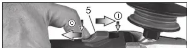
Switching on: Push the slide switch (5) forward. For continuous activation, now tilt downwards until it engages.
Switching off: Press the rear end of the slide switch (5) and release it.
Machines with paddle switch (with dead man function):
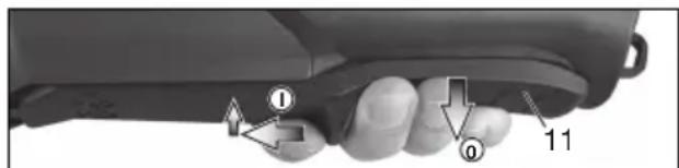
Switching on: Slide paddle switch (11) in the direction of the arrow and then press the paddle switch (11).
Switching off: Release the paddle switch (11).
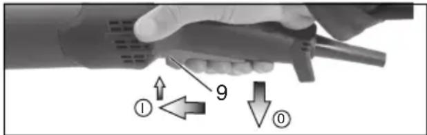
Machines with the designation W...RT: Torque activation (with dead man's lever)
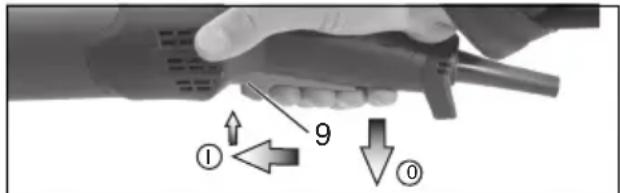
Switching on: Slide the trigger switch (9) forwards and then push the trigger switch (9) upwards.
Switching off: Release the trigger switch (9).
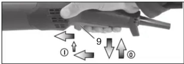
Machines with the designation W...RT: Continuous operation (depending on features)
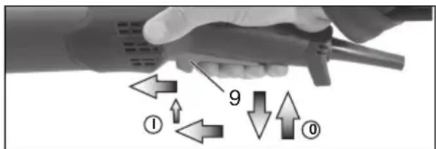
Switching on: Switch the machine on as described above. Now slide the trigger switch (9) forwards again and release in the front position to lock the trigger switch (9) (continuous operation).
Switching off: Push the trigger switch (9) upwards and release.
8.3 Working Directions
Grinding and sanding operations:
Press down the machine evenly on the surface and move back and forth so that the surface of the workpiece does not become too hot.
Rough grinding: position the machine at an angle of 30irc - 40irc for the best working results.
Cutting-off operations:
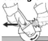
Always work against the run of the disc (see illustration). Otherwise there is the danger of the machine kicking back from the cut out of control. Guide the machine evenly at a speed
suitable for the material being processed. Do not tilt, apply excessive force or sway from side to side.
Wire brushing:
Press down the machine evenly.
8.4 Lanyard connection (depending on equipment)

Safety warnings specific for use at height. Read all safety warnings and instructions.
Failure to follow the warnings and instructions may result in serious injury.
- Only for use by trained persons. The users must be trained with regard to tool securing and the use of tools at heights.
- Always keep the tool tethered when working "at height". Only use appropriate metabo brand lanyard (maximum length is 2 m (6.5 ft) with sufficient damping capacity). The maximum permissible fall height for lanyard (tether strap) must not exceed 2 m (6.5 ft). Use only with lanyards appropriate for this tool type and rated for
at least the mass of the tool including all used accessories.
- Read and follow the operating instructions of the tool securing lanyard!
- Inspect tool (especially the eyelet) and lanyard before each use for damage and proper function (including fabric and stitching). Do not use if damaged or not functioning properly.
- Do not anchor the tool lanyard to anything on your body. Anchor to a solid mounting option that can withstand the forces of a dropped tool.
- Crush, cut or entanglement hazard. Do not use near moving parts, mechanisms or running machinery.
- Do not change the attachment point for the lanyard on the tool and also do not use it for other purposes than those described in this manual.
- Only attach tool to a lanyard with a locking carabiner. Do not attach by looping or knotting the lanyard. Do not use rope or cord. Only use carabiners with two-way locking system. Do not use single action spring clip carabiners.
- Attach the lanyard in a way that the tool will move away from the operator if it falls. Dropped tools will swing on the lanyard, which could cause injury or loss of balance.
- Do not attach more than one tool to each lanyard.
- Only use specifically intended attachment points (eyelet (10)) to attach the lanyard at the tool. NEVER modify tools to create attachment points.
- Do not attach lanyards to tool in a way that keeps guards, switches or lock-offs from operating properly.
- Keep lanyard away from the accessory.
- Protect the tool security lanyard from flying sparks and chips.
- Protect the tool securing lanyard from sharp edges, blades, chips, etc. Do not step on the tool or the tool securing lanyard.
- Do not use lanyards or attachment devices to get additional leverage from the tool.
- Make sure that there is sufficient space in the area where the tool might hit the floor. No persons must be endangered in that area.
- Replace the rope after a fall and check the tool for damage. After each fall, have the machine checked for damage by a trained specialist and repaired if necessary.
- Do not try to catch the falling machine. This might result in injuries.
8.5 Rotate gear housing
See illustration E on page 3.
- Disconnect from the power supply.
- Unscrew the fastening screw (a) of the lever (17). Remove the screw, lever (with its sheet metal part) and put aside.
- Unscrew the 4 gear housing screws (b).
CAUTION! Do not remove the gear housing!
- Turn the gear housing to the desired position without removing it.
- Screw in the 4 gear housing screws (b) in the available threads! Tightening torque = 3.0 Nm +/- 0.3 Nm.
- Slide the spring that pushes the lever in position to the side and re-insert the lever (17) (with its sheet metal part), and fix with the fastening screw (a).
Tightening torque = 5.0 Nm +/- 0.5 Nm. Check the lever for correct function: it has to be under spring tension.
9. Cleaning
Particles may become deposited inside the power tool during operation. This impairs the cooling of the power tool. Conductive build-up can impair the protective insulation of the power tool and create an electrical hazard.
The power tool should be cleaned regularly, often and thoroughly through all front and rear air vents using a vacuum cleaner or by blowing in dry air. Prior to this operation, separate the power tool from the power source and wear protective glasses and suitable dust mask. Ensure appropriate suction is available when blowing out vents.
10. Troubleshooting
Machines with VTC, TC and VC electronics:

The electronic signal display (7) lights up and the load speed decreases (not W...RT). There is too much load on the
machine! Run the machine in idling until the electronics signal indicator switches off.

The machine does not start. The electronic signal display (7) (depends on model) flashes. The restart protection is
active. If the mains plug is inserted with the machine switched on, or if the power supply is restored following an interruption, the machine does not start up. Switch the machine off and on again.
11. Accessories
Use only genuine Metabo accessories. See page 6.
Use only accessories which fulfil the requirements and specifications listed in these operating instructions.

Always use the suitable accessory and the prescribed guard for the matching guard for application. See page 6. (Illustrations are namples).
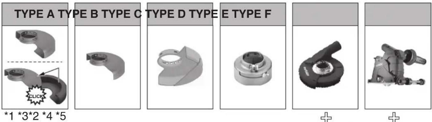
Application:
1 = surface grinding
2 = cut-off grinding
3 = drilling of holes
4 = wire brushes
5 = grinding with sanding paper
6 = polishing
Accessories:
1.1 = grinding wheel
1.2 = cup wheel (ceramic)
1.3 = diamond cup wheel "masonry/concrete"
2.1 = cut-off wheel "metal"
2.2 = cut-off wheel "masonry/concrete"
2.3 = diamond cutting disc "masonry/concrete"
2.4 = dual-purpose diamond cutting discs (combined grinding and cutting disc)
3.1 = diamond drill bits
4.1 = wheel brush
ENGLISHen
4.2 = cup brush
5.1 = flap disc
5.2 = backing pad for sanding sheets
6.1 = polishing accessories
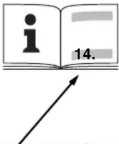
prescribed guard:
Type A = cutting guard / guard incl cutting guard slip for cutting-off operations
Type B = guard for grinding
Type C = guard for grinding and cutting-off operations (combination)
Type D = guard for cup wheel
Type E = extraction guard for surface grinding
Type F = extraction guard for cutting-off operations
Other accessories:
(see also www.metabo.com)
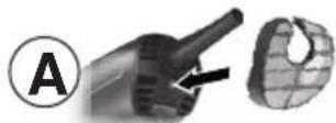
A Dust filter
The fine mesh filter prevents coarse particles from entering the motor housing. Remove regularly and clean.
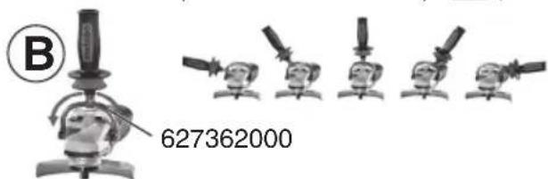
B Multiple position bar for side handle
Permits numerous handle positions.
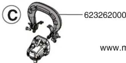
C Bar side handle
For a complete range of accessories, see www.metabo.com or the catalogue.
12. Repairs

Repairs to electrical tools must be carried out by qualified electricians ONLY!
A defective mains cable must be replaced only with a special, original mains cable from Metabo available from the Metabo service.
Contact your local Metabo representative if you have Metabo power tools requiring repairs. For addresses see www.metabo.com.
You can download a list of spare parts from www.metabo.com.
13. Environmental Protection
The generated grinding dust may contain harmful substances. Dispose appropriately.
Packaging materials must be disposed of according to their labelling in accordance with municipal guidelines. Further information can be found at www.metabo.com in the “Service” section.
Observe national regulations on environmentally compatible disposal and on the recycling of disused machines, packaging and accessories.

Only for EU countries: Never dispose of power tools in your household waste! In accordance with European Directive 2012/
19/EU on waste electrical and electronic equipment and its implementation in national law, used electrical tools must be collected separately and handed in for environmentally compatible recycling.
14. Technical Specifications
Explanatory notes on the specifications on page 4.
Changes due to technological progress reserved.
∅ = max. diameter of the accessory
tmax,1 = max. permitted thickness of the clamping shank on accessory when using 2-hole nut (15)
tmax,2 = max. permitted thickness of clamping shank on accessory when using "Quick" clamping nut (1)
tmax,3 = roughing disc/cutting disc:
max. permitted thickness of accessory
tmax,4 = max. permitted thickness of wheel-type wire brushes
M = spindle thread
I = length of the grinding spindle
n*=no-load speed (maximum speed)
P1 = rated input power
P2 = power output
m = weight without mains cable
Measured values determined in conformity with EN 62841.
Machine in protection class II
\~ AC Power
* Machines with the designation WE... : Energy-rich, high-frequency interference can cause fluctuations in speed. The fluctuations disappear, however, as soon as the interference fades away.
The technical specifications quoted are subject to tolerances (in compliance with the relevant valid standards).
Emission values
These values make it possible to assess the emissions from the power tool and to compare different power tools. Depending on the operating conditions, the condition of the power tool or the accessories, the actual load may be higher or lower. For assessment purposes, please allow for breaks and periods when the load is lower. Based on the adjusted estimates, arrange protective measures for the user e.g. organisational measures.
The grinding of thinner metal sheets and other workpieces with large surfaces that easily
vibrate can lead to a significantly higher overall sound emission (up to 15 dB) than the sound emission values specified. The sound radiation of such workpieces should be prevented to the greatest extent possible by means of suitable measures, such as fitting heavy, flexible damping mats. The increased sound emission must also be taken into account when assessing the risk of noise exposure and selecting suitable hearing protection.
Vibration total value (vector sum of three directions) determined in accordance with EN 62841:
ah, SG = Vibration emission value (surface grinding)
ah,DS = Vibration emission value (sanding with sanding plate)
ah,P = Vibration emission value (polishing)
Kh,SG/DS/P = Uncertainty (vibration)
Typical A-effective perceived sound levels:
LpA = Sound-pressure level
LWA = Acoustic power level
KpA, KWA = Uncertainty
During operation the noise level can exceed 80 dB(A).

Wear ear protectors!
FRANÇAISfr
Notice originale
Voir page 2, figure B.
K _ n, SG / DS / P = incertitude (vibration)
11 Paddle-schakelaar *
11 Interruptor Paddle *
Se side 3, illustration E.
∅ = maksimal diameter for
indsatsværktøjet
MAGYARhu
(hu6t1 hwlwnwl htpwwlw6nlpjwup)
7. Znlywulwulwnwlh wktnwnpnul

Cupfug ulwqunwly hwuklp lwwd wdpuguklp ahem wfgwnkL uwpfp kltlnpwnuignignuhg' hwuklnl
lupngwlq lwpnwlhg: Uwpfq wktnf t, wfgwnmd ylfhwlpnd ylfgh huh lplwfgmpd:

1 unpnq ulqwjwnwh6tpnq wejwuntlhu, wfujwnwhqnlpjwghw6ng6tphg t6tlnq oqnwnqnpdL hnpnq
vhwqwnwhgtph hndwp hwnwnh gmjwnntuqlmd qwwnjw6p (wku qlmjo 11. Nmpwqm6tp)
7.1 Pth ulkwnlgnuf
- Pll mptlmhl2 lnhml (4) utnlt, atnfml mwnlglbl llp (2) mflmli, dshsh mptlmhl2 lnhml wdpmhglh:
7.2 Zhhuqunwuhupugnuf
WA..., WBA..., WE...A...'
Stu 2 2 Uqmp A

Pfghwuhwunmpulperenh hluwulqwlwnwlp (3) wdnlp wlnqunpulud l, hph dpm: Pfhyuwa djoua wdhjnlwujhli
hnqnn/hwnpnn umpftph ntkwfmü, hwfiyn htfwnulqnlmwnwh mfihpmdkcm st:

Pfghwuhwnwpulpenn hfgwnlquwnulh (3), hqlnq ulpwulwnulh h wpuqwuknqhy dwfhlh (1) mlqnqnpuwli
dwtptkftpp qtknf t dwtmp Lh6f6 : U.6hpmdtcmmppjmb qtkpfnd dwtpkf :
- Slqnwulwlk, hqlwulwalwnwlp, hfffuuhwwrwnpwulhenn lgwenclppb/hffuuhwwrwnwlh (3) dpu: Znhwulwalwnwlp upkuf t, hwnlwnmpunswl fwnntgjmd Lhfhi hfffuuhwwrwnpwulhenn hffwuulwwrwnwlh dpu:
WPB..., WEVB 1...'
Shu 12 2 Uqup B
- Stnwlwjdwg lgwenclppp/htgwulwqwnwnlp (14) Gunktglt h1h lpwa: 2tGwulwqwnwnlhl qhpfp 6hcwn t, tpt w3g 2h wpwnnlwd h1h lpwa:
- Znhwulwunwnlp wkqwhwlj lgwencppb/hkfuulwquwnwlh (14) dpw: Znhwulwunwnlp wklnf h hdwwwpwyswh guinglud lgh hkfuulwquwnwlh dpw:
20.3bfbthy
7.3 Upwquuknqihy dwgkhj hupwgnui/hwlinui (hwluwlwd t uwpfh wkuwllhg)

Upwqwutnúh₂ dufitlḥ (1) wúpwgnú.

Upmqmwuknqdyh ydwklhp (1) wapmgfkl yhwjli «Metabo Quick-System»- qhwfaid: Uja wupflpp hwfuyslhp uwl jhl wklenwuhduwli «M-Quick» qpqlwdfaid hwpuhp jnd (4)

Bpl. oqnuqnpdjln uhpulwnuhp aqufi huunlmdnif 7.1 aú -hg huun l, wpuwquuknhs awfiklp hhpwnnup qnlü f: Uju nqufniü oqnuqnpdif awfiklp kplnc apnd (15), npp aquniü f, tphqnqudgh npapawlh qfinrpjnmip:
- b 1 h ulkwnwlncif (mku qlnlp 7.1):
- Quick wpwqwutnqshs dwgthp (1) wjgwtu guuntggtl hlh (2) ypw, npwtuqh 2 qwnswggtp6 pghgt6 hlh 2 wlnuhygtph dh: Slw ghwpp lsy 2
- Qlnfni] dqli mpwquulqihy uufilhp duiwgnjgh uifh nlnqnlpjwiup:
- 2n1wulwulwnwlp dwu wgnlgh ulwf h nynnipjwdp ni dtn wnntgltlnl aqtf wpwqwutnihz dwitlp:
Upuquuknqihs dufiklph (1) hufinul.

hLL hwpnn bf lq6q6tggtL, utn6tlnj [llp M-Quick uthwnwlqfm6 lq6wlp (4) dhwjb myb ytbqfmd, tpk k-wpuwquuknqhy dwuiklp (1) mtkwnnpiuud L:
- U62wntng hwn qnpdlf p nnc dwnfuwl ywnuyl f;
- Uphsh hnhwuhqwnwlhp qwnwlhl ywnwphtlp utnütf llp M-Quick lwpahp uktwnwljs lynfwlhp (4): Quick-wpwuwutnühs dwiflhp (1) hfnipnjg pntuwniid t, dwn hlu wnnijunnl h lwpqn t, wnwbg lpwgnighs mid qnpdwnptlni lww qnpdhf oqnwnpnduig wnnwnwwhwbjtl:
7.4 tplm wligftpml ûwltthh wúpwgnuð/hwfinuð (hwluvlud l, uwpfh ünnl.lhg)

bplqm qllwm6[wwwnjhi w6gftpni] u6kth oquwqnptlju hli uukwnlpfmi hpiwhu (4) utnptf uhwji myi
dunfuih, kpp hllp wfpngnlpjwdp hufiq L mnkl:
bplm w6gftpml 6m6thp 2 qnn6tpp wnpptp t6; bplm w6gftpml 6m6thp 6tpapwnwnmlt p h1 ypm hukhyml ktpm.
Shu 12 Uhp C
- X) fwpwq hqlmwlqmnwlqftp.
Ompkuq puapuh hnhmuulpuuunwlp nuquhnd] uufpugih, khpnt uigflpnd] duftlqh kynlqp (15) qluqh ihph. nhpfnj l:
Y) Zwww.hqhwulwjwnwlftkp
Ompuqh tplm wfgfpml dnmgthp yphn fuunh hll ypm, gpm krm6p (15) ythqh gtpfh yhpfml k: - P 1 h u k l n u m l p u i f: b p h 1 q n f u w i f h q n u p a u w i h f (16) oq 1 u p r j u m d p l p h q 1 u g f 1 h p n l d u w i l d h p (15) a q l 1 d u w i w n g n 1 g h u 1 w f h n 2 q 1 u p r j u m d p :
bpln uigftpnj dmftlph hufni.
- Pth uktanulqni (mku qnljo 7.1): bplqunpufh npapawlh (16) oqfincpjwup kphnc uigfklpnl dwkthp (15) upawlyk dwawgnlgh uufh hultwnwh aqnqnpjwup:
8. Чршнній
U'hwgnid. phwljwlnp wfgwnhp (11) wthwewpdtL uqufh mnqnipjwdp, wffinhtuk utnutL phwljwlnp wfgwnhp (11):
U.figunnii. pugil phuhwunw uqwnhyn (11):
UfuJwufuWf iLg W...RT mnntp wqnpafuwnqn qnpdHffbP'
Uhfgpwwppwjhl dihwgnl (9qnlinipjwli fniflghwnnl/lfffglwljwlq)
U'huqngn#. u#n#lj w#p#jwnh#w#l h#w#lp (9) wn#w nt#w#wpd#l, w#f#chknl dhwg#w# l#w#lp (9) q#pl# ut#n#l:
U. U. U. U. U. U. U. U. U. U. U. U. U. U. U. U. U. U. U. U. U. U. U. U. U. U. U. U. U. U. U. U. U. U. U. U. U. U. U. U. U. U. U. U.
UfuImfimfi uIg W...RT umntp qmpmfimqn qnpdhffilp
Slwlqli wejwnwnfui hdi hlyh lhyw (lhywld uwpfhi wtuwlg)
U'hwgnid. Uwpfp dhwglk1, hfswlu fciqw l, dlplnld: 2hdw dhwgduh utndwlnfwllp (9) glnphg wtnwcwpdtl nkwh wnwg h pwg pnghk1 wnwgwnjhiq nhpfnld, npwtuqh dhwgduh utndwlnfwllp (9) ubtnwlhl (whwlgm mclwmnmfimjluktd):
U. U. U. U. U. U. U. U. U. U. U. U. U. U. U. U. U. U. U. U. U. U. U. U. U. U. U. U. U. U. U. U. U. U. U. U. U. U. U. U. U. U. U. U. U. U. U. U. U. U. U.
8.3 2pwhwfiqftp wchwnnwifh hwdwp
P _ 2 = S _ p | nqhqnpnlpjnlf .
m = dot P _ we unwifg ufinigfuhi uph
Quhk _ I h _ hu n p f i k p u m EN 62841 c n p d h :
q.npdhf quccunqw6nipjw6 ll qwhh
_ nhnpwlquf hnuuff
* Uwpftp WE... w6qw6gcnfnl 't6tpqhwjnl hwpmwn pwpdp hwbw|wwlqwgm pywup jw6qwpmuf6tpp hwpnq t6
wunljmlph fuwulh unwnuulnuklp unwnyugk: Tpwuf hpqh6 qwghtwnw6, tpp lwmqwpnnf6tpp ytpmw6:
Uclud mklufihqulwli mlljwnflepp nukli pnljwnplh clqnufilp (huifuunwnulwli qnpdnq unwufupnfil.ph):

Upunwltumu6tph wpdtf6tp
Lcifud mpdhffkph oqfuppywde himpwnlp t unwufm le hundawmle wju qnpdhaf le wjl qnpdhffkpnl wehwnuwfgh phan wpwnwflannwllkph fuiwuhfpp: Luu lhpwnndwi uqwjdwfklph, qnpdhfi jhfwlgh le lhpwnndn wqpwqwflph' qhnlnpwnnf, atdsmwnf lqn fijmqnuf t qhnwnngh wpwnwflannwllkph fuiwulp: Zmejwphl dwnwfuwl hucilh unkf plnqhyacflkpp lc gudp plnfiwdncpjwli wehwnuwlfwjhi qhnlp: Uwnwnlp mpdhffk p unwufwnig hkun oqnwqnpdngh hundwp atnfgwpltf hundwwwnwnuwwli wwcwnuwfgh zhqngftp gwh lqmqdwhtprwzywlw6 zhqngftp:

U'd üwlplund pwnw phplqkpp lwnd panl pppnwngwn wll wepwnwngfuwhü üwutpp hnytlp lwpnq hwhgqtgktl afinip wnfmlyh üwlwpnwqh qqwth qtpwqwfgwug (ühlsh) 3) fclwud pnjlwnptlh wnfmluh wpdtftgtp hwnbduw:
Uwth qkwnuflp dewhlihu wchpuodhen l hluwpwlaphlu fuwqghkl wpdwhlqn wnqnlpr ophluw ykwnwh nuwl dwlp, glnf wqnulpr llwunn qnpqtp wtqnoptlnj: Unanlhy wqntgnipjwi gwnqpl qwhwnltju h lunnpijpwi hwwnwmwnwnw ywcwnpwhi z shnggtp pfwnptlu wftnf t hwclh mngl fml mltlh pmpap wnufih wpdwhufwi hluwpwlapnlpjnclp:
S###m#n##tph ###h###np mpdtfp (kptf mqqnpjm#tph ###h######jhi qni#mp)' hnu#m#njg EN 62841 knp#h.
a _ h, SG amp; = S _ mmmfinuflkph mpdf amp; (U _ wlkphufkphhnlqnu)
a _ h, DS amp; = S _ wwwfinlglphwpdtf amp; (Z _ η wouwjuwnwlqylhnlmnf )
a _ h, P amp; = S _ mmmfinifgtphmpdtf amp; (_ mjlkgmuf )
K _ h, SG / DS / P = U _ ilpujnlfinlpjnll (mmmmfinldik _ p)
U _ n finl h ^ A - nwhwhhhdwlpwpwh.
L _ pA = U _ lqmunhlq fGcdwgdwlqmprmlq
L _ WA = U _ η ifm h _ hqnpmpjmfifmlqmpnml
K _ pA, K _ WA = S _ m u n m f i n u f
Uc|wuuugf| p|p|ngfm| w|n|m|h w|u|h|g|g| l|w|n| h|q|p|w|q|g|g|l 80 nf (U):

Qupunwnlp lptl wwcunwghs whugwhlwl:
(Vt ka saidilt www.metabo.com)
A Tolmukaitsefilter
" Frps Qing "mogdn = 2.1
natural_image
Icon showing an open book and a recycling bin with a circular arrow (no text or symbols)Metabowerke GmbH
Metabo-Allee 1
72622 Nuertingen
Germany
www.metabo.com
metabo®


- Original instructions
- Declaration of Conformity
- For UK only:
- Specified Use
- General Safety Instructions
- Special Safety Instructions
- ENGLISHen
- Kickback and related warnings
- Safety warnings specific for grinding and cutting-off operations:
- Additional safety warnings specific for cutting-off operations:
- Safety warnings specific for sanding operations:
- Only for WEVA 15-125 Quick, WEVA 15-150 Quick: Safety warnings specific for polishing operations:
- Safety warnings specific for wire brushing operations:
- Additional Safety Instructions:
- Using the correct guard:
- Reducing dust exposure:
- Overview
- See page 2.
- Commissioning
- Attaching the additional handle
- Attach the safety guard
- Attaching the grinding disc
- Locking the spindle
- Placing the grinding wheel in position
- WPB..., WEVB 1...:
- Securing/Releasing the "Quick" clamping nut (depending on features)
- Securing the "Quick" clamping nut (1):
- Releasing the clamping nut (1):
- Securing/Releasing the 2-hole nut (depending on features)
- Releasing the 2-hole nut:
- Use
- Adjusting the speed (depending on features)
- Switching On and Off
- Machines with slide switch:
- Machines with paddle switch (with dead man function):
- Machines with the designation W...RT: Torque activation (with dead man's lever)
- Machines with the designation W...RT: Continuous operation (depending on features)
- Working Directions
- Grinding and sanding operations:
- Cutting-off operations:
- Wire brushing:
- Lanyard connection (depending on equipment)
- Rotate gear housing
- CAUTION! Do not remove the gear housing!
- Cleaning
- Troubleshooting
- Accessories
- Application:
- Accessories:
- prescribed guard:
- Other accessories:
- (see also www.metabo.com)
- A Dust filter
- B Multiple position bar for side handle
- C Bar side handle
- Repairs
- Environmental Protection
- Technical Specifications
- Emission values
- FRANÇAISfr
- Notice originale
- MAGYARhu
- Znlywulwulwnwlh wktnwnpnul
- Pth ulkwnlgnuf
- Zhhuqunwuhupugnuf
- WPB..., WEVB 1...'
- 20.3bfbthy
- Upwquuknqihy dwgkhj hupwgnui/hwlinui (hwluwlwd t uwpfh wkuwllhg)
- Upuquuknqihs dufiklph (1) hufinul.
- tplm wligftpml ûwltthh wúpwgnuð/hwfinuð (hwluvlud l, uwpfh ünnl.lhg)
- bpln uigftpnj dmftlph hufni.
- Чршнній
- Uhfgpwwppwjhl dihwgnl (9qnlinipjwli fniflghwnnl/lfffglwljwlq)
- 2pwhwfiqftp wchwnnwifh hwdwp
- Upunwltumu6tph wpdtf6tp
- (Vt ka saidilt www.metabo.com)
- A Tolmukaitsefilter
Brand : METABO
Model : WEPBA 17-125 Quick RT
Category : Sander