
Alesia - Chair Vermeiren - Free user manual and instructions
Find the device manual for free Alesia Vermeiren in PDF.

| Product type | Transport chair (reclining chair) |
| Brand | Vermeiren |
| Model | Alesia |
| Total weight (without options) | From 33 kg |
| Maximum load | 140 kg |
| Total length (seated position) | 800 mm |
| Total length (reclined position) | 1330 mm |
| Total width | 700 mm |
| Seat width | 540 mm |
| Seat height | 530 mm |
| Seat depth | 480 mm |
| Backrest height | 800 mm |
| Backrest recline | Up to 30° backward |
| Seat tilt | Approximately 12° backward, 3° forward |
| Armrest adjustment | Height adjustable from 0 to 270 mm |
| Footrest | Stowable under the chair |
| Parking brake | Central on both rear wheels |
| Wheels | Swivel casters front and rear (125×32 mm) |
| Usage | Indoor only |
| Frame material | Steel with spray coating |
| Upholstery | Leatherette |
| Routine maintenance | Clean with damp cloth, no harsh chemicals |
| Optional accessories | Document holder, side cushions, IV pole, etc. |
| Standards | Directive 93/42/EEC, EN 12182:2012 |
Frequently Asked Questions - Alesia Vermeiren
User questions about Alesia Vermeiren
0 question about this device. Answer the ones you know or ask your own.
Ask a new question about this device
Download the instructions for your Chair in PDF format for free! Find your manual Alesia - Vermeiren and take your electronic device back in hand. On this page are published all the documents necessary for the use of your device. Alesia by Vermeiren.
USER MANUAL Alesia Vermeiren
Instructions for specialist dealer
This instruction manual is part and parcel of the product and must accompany every product sold.
Version: B, 2020-02
FR
All rights reserved, including translation.
Technical details....3
Assembly 4
- Tie-wrap ....4
- Seat....4
- Back ....5
Headrest (optional) 5
Seat angle 6
Adjusting the back 6
Armrests 7
Footplate 8
Brakes (central locking) 8
Directional wheel 9
Accessories 9
- Document holder (B79)....9
- Pads (L04)....9
- Serum holder (B52)....10
- Multi-purpose holder ....11
- Adjustable legrest....11
- Adjustable / Widened armrests....11
• Treatment table (B12)....12
- Urine bag holder....12
Transport 12
Using ramps 13
For your safety....13
Making regular checks....13
Inspection 14
Care 14
Disinfection 15
Storage 16
Disposal....17
Guarantee....17
Conformity 17
Maintenance plan 18
Disinfection book 18
PREFACE
First of all we wish to thank you for the trust you placed in us by selecting one of our products.
Vermeiren products are the result of research and experience over many years. In development, simplicity of operation and servicing was particularly emphasized.
The product's service life depends very much on the care with which it is used and handled. This user manual aims to help familiarize you with using your recliner. You will also find advice as to how to keep your product in good working order and ensure that it will have a long service life.
This user manual relates to the latest version of the product. However, Vermeiren reserves the right to introduce changes without any obligation to adapt or replace previously delivered models.
Remember that, by following these instructions, you will help keep your recliner in the best possible condition and fully-functional even after many years' use.
If you have any further questions, kindly consult the dealer.
APPLICABILITY
In the ALESIA mobile chair you have acquired a product that has been developed with an enormous emphasis on comfort. The ALESIA mobile chair should only be used indoors. It may not be used outdoors. Persons who are to be moved with the chair must at least have sufficient bodily control and should have no balance disorders that might affect sideways stability, otherwise precautions should be taken to secure the patient. It should not be used as a ladder, or as a resting place for hot, cold or heavy objects or to move items. Read this user manual thoroughly to familiarize yourself with your product.
The equipment enables use in cases where movement is restricted due to:
● Paralysis/weakness (while retaining control of the torso)
- Joint injuries
- Illnesses such as heart and circulation failure
The indication should take into account factors such as the following:
● Size and weight (max. load 140 kg)
● Physical and mental condition
- Living environment
A guarantee can only be given when the product is used under the circumstances specified above and for the intended purposes.
GENERAL NOTES
The frame of the ALESIA chair is made of high-quality, powder-coated steel. The use of synthetic leather covers enables easy care and cleaning. The seating systems were designed based on ergonomic principles for your comfort.
The angles of the seating system, the back and the legrest can be adjusted using a pneumatic cylinder.
ALESIA COMPONENTS
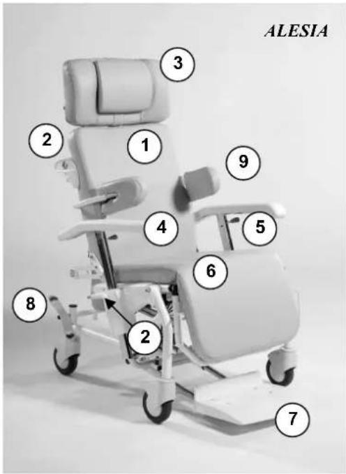
1 = Back
2 = Adjust angle of back
3 = Headrest (optional)
4 = Armrest
5 = Lever to adjust armrest
6 = Seat/legrest
7 = Footrest
8 = Foot lever brake (central lock), foot lever for direction wheel
9 = Torso pad (optional)
10 = Foot lever for angle of seat (not shown)
TECHNICAL DETAILS
(Given for the fully-assembled, standard version). Please note that adding accessories will alter the technical details accordingly.
| ALESIA | |
| Total length in seated position 800 mm | |
| Total length in lying position 1330 mm | |
| Total width 700 mm | |
| Seat width 540 mm | |
| Height of backrest 800 mm | |
| Total height with headrest (optional) 1330 mm | |
| Height of seat 530 mm | |
| Seat depth 480 mm | |
| Height of armrests 0 mm - 270 mm | |
| Total weight * From 33 kg | |
| Max. load 140 kg | |
| Angle of back (150N pneumatic spring) Approx. 30° | |
| Angle of seat (400N pneumatic spring) Approx. 12° | |
| Legrest length 330 mm | |
| Legrest adjustment (optional) | Approx. 85° (stop notch) |
| Minimum turning diameter | 1690 mm |
| Front steering castors | 125 x 32 |
| Rear steering castors (central locking) | 125 x 32 (with brake) |
We reserve the right to introduce technical changes. Differences of +/- 15 mm/1.5kg, 1.5° are possible.
* Excluding headrest and accessories.
ASSEMBLY
- TIE-WRAP
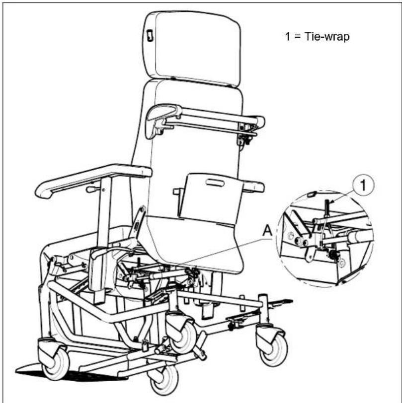
For the good function of the gasspring (backrest inclination) there is mounted a tie-wrap ①.
Do not remove this tie-wrap ①!
- SEAT
The seat is clipped to the basic frame with clamps.
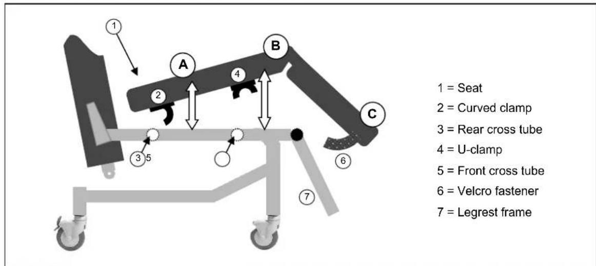
A Lay the seat (1) at a slight angle to the curved clamp (2) in such a way that the clamp catches beneath the rear cross tube on the basic frame (3).
B Press the front of the seat (1) downwards so that the U-clamp (4) engaged on the front cross tube of the basic frame (5).
B The Velcro fastener (6) is used to attach the lower leg padding to the braces on the frame of the legrest (7).
If you wish to remove the seat, follow the reverse procedure.

Ensure that no objects or body parts get caught between the seat and the frame!
- BACK
When assembling the back, the pneumatic spring is connected to the rear frame with a safety pin (1).
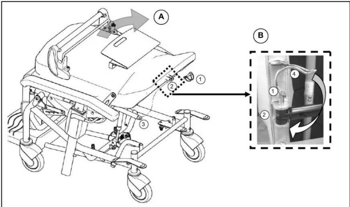
A Align the rear frame so that the retainer on the lower part of the back (2) and the mounting lug of the pneumatic spring (3) are above one another.
B Guide the safety pin (1) through the rear retainer and the pneumatic spring. Then tighten the safety pin (1) by guiding the tension spring (4) over the pin until the pin juts out above the end of the locking pin.
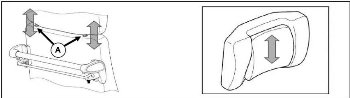
• HEADREST (OPTIONAL)
The headrest is inserted into the retainer of the back section (A) and the pillow height can be adjusted. The pillow can be removed or attached using the pushbutton on the lower end of the sliding plate on the pillow.
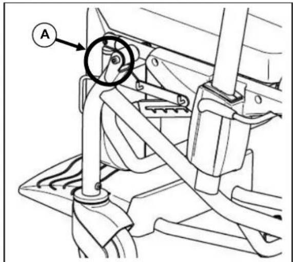
SEAT ANGLE
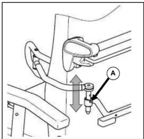
An attendant can use the pneumatic spring to angle the seat unit, gradually, up to 12^ , into the most comfortable position, and to angle it forwards up to 3^ to assist the patient to get in and out of the chair.
natural_image
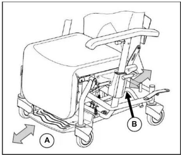
Technical line drawing of a mobile medical mobility device with wheels and control panel (no text or symbols)With your foot, gently press downwards the release lever (highlighted in blue) on the right rear wheel for the seat angle and adjust the seat unit to the position you want, by clutching the handle and pushing the seat down or pulling it up. To fix it in the position you want, take your foot off the release lever.

Ensure that the rear wheel is not underneath the blue release lever, blocking it.

Take care, when adjusting the seat angle, that the wheelchair does not start moving if the brake is not holding it in place.
If you wish to move a patient, you should always select a gentle seat angle or the footplate (if in use) will drag along the ground while doing so.
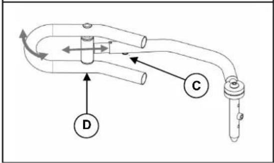
ADJUSTING THE BACK
The patient or attendant can incline the back section backwards by up to 30°.
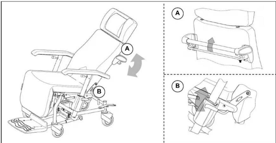
USE BY AN ATTENDANT
Pull the release clip beneath the handle towards the handle. While keeping the release lever held, the back can be moved to the position you want by gripping the handle. To fix the back in the position you want, let go of the release clamp beneath the handle.

Take care, when adjusting the back, that the wheelchair does not start moving if the brake is not holding it in place.

The pneumatic spring is designed to take the patient's weight. Without a weight and if the release lever is not pressed, the back will always shoot back to the furthest forward position.
BSE BY THE PATIENT
Pull the release lever, on the left or right next to the armrest retainer, gently upwards. While keeping the release lever held, the back can be moved to the position you want by - while you are seated - gently pressing your weight backwards against the back section or by slightly bending your back forwards you will move the back of the chair forwards. To fix the back in the position you want, let go of the release lever beneath the handle.

Take care, when adjusting the back, that the wheelchair does not start moving if the brake is not holding it in place.

The pneumatic spring is designed to take the patient's weight. Without a weight and if the release lever is not pressed, the back will always shoot back to the furthest forward position.
ARMRESTS
You can adjust the height of the armrests and lower them to the height of the seat in order to move the patient sideways.
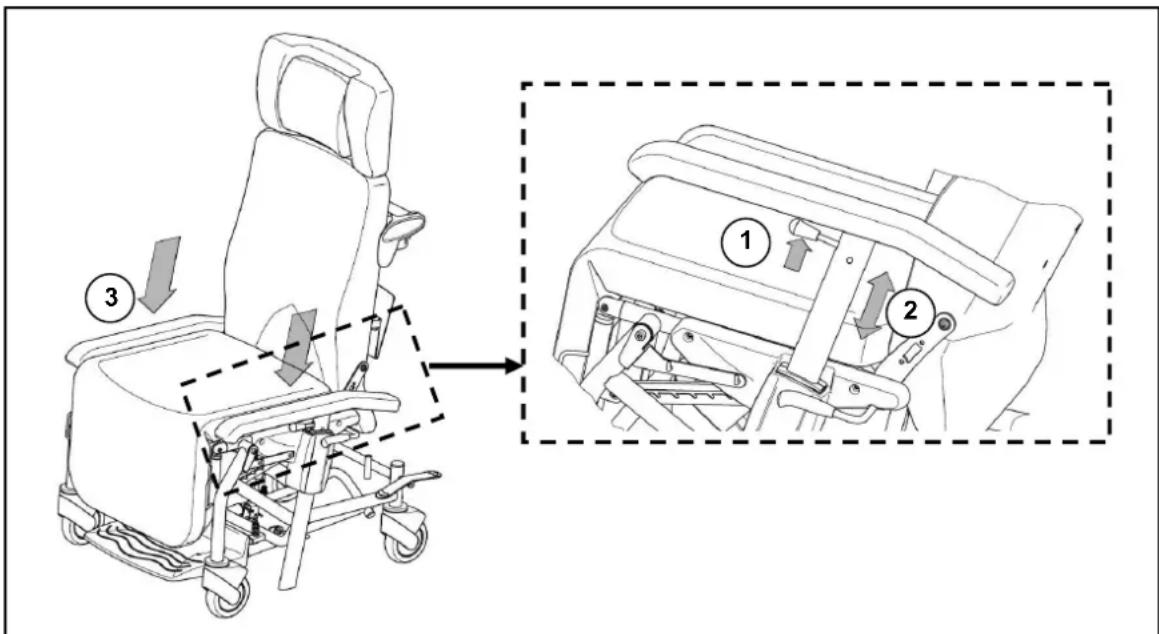
• Pull the armrest's release lever (1) upwards (towards the arm pad) and keep it held.
- Move the armrest to the height you want (2) and let go of the release lever (1) so that the armrest can engage.
- To move the patient sideways, pull the release lever (1) and push the armrests down to the height of the seat(3).

The armrest is not locked at seat height.

When moving adjustable parts, ensure that no body parts or objects come within the range of the adjustment and get caught!
FOOTPLATE
The footplate can be pulled out from beneath the chair to be used or pushed back beneath the chair when not being used. When the footplate is pulled out, a weight should be kept on it.
A Grip the front end of the footplate and pull it out till it locks or, similarly, push it back beneath the chair.
B An attendant can push the footplate forwards using the rear handle, or pull it by the handle back beneath the chair.
The footplate does not fold up - when not in use it should be pushed/pulled beneath the chair.
When the patient is getting in or out of the chair, the footplate must be pulled out and they should step on it. The suspension mechanism allows the footplate to drop down so that it is entirely flat on the ground.

The brake should always be applied before a patient gets in and out.

When the footplate is used to move a patient, the seat should be angled backwards, as only then will the suspension mechanism raise the footplate slightly.
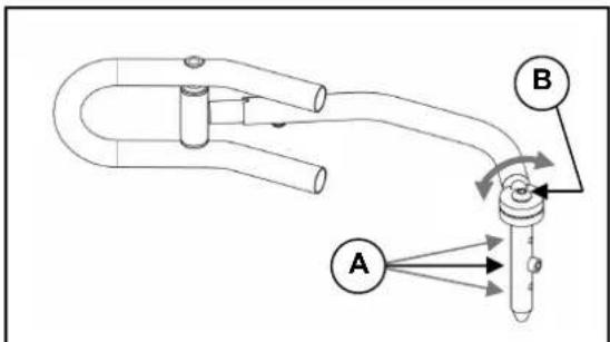
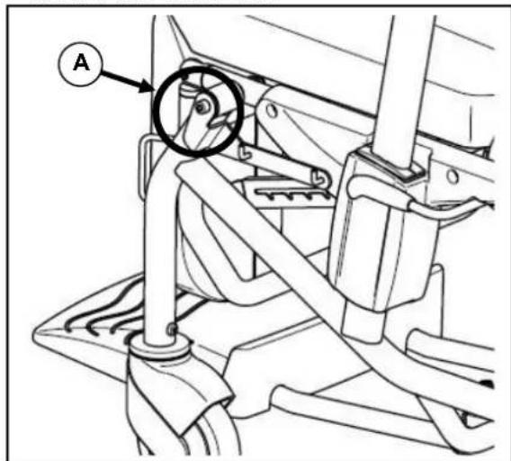
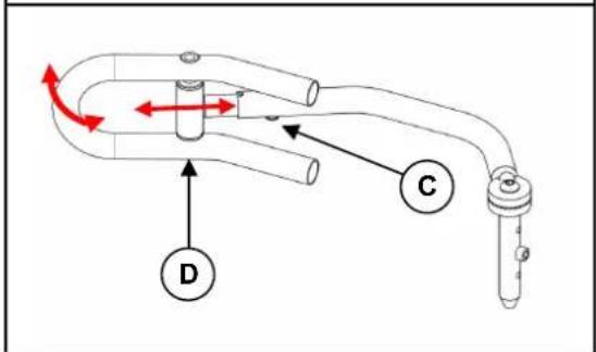
To stabilise the chair, the two rear castors are fitted with a centrally locking brake.
natural_image
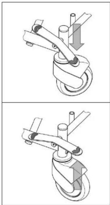
Technical illustration of a mechanical device with two views showing a lever mechanism (no text or symbols)Engaging the parking brake
Push downwards with your foot on the release lever on either the right or left rear castor (labelled red) until the brake audibly engages. The rear castors are now locked and will not roll or turn.
Releasing the parking brake
Push upwards with the toes of your foot against the release lever on either the right or left rear castor (labelled red) and the rear castor brake will disengage.
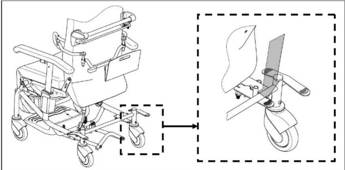
DIRECTIONAL WHEEL
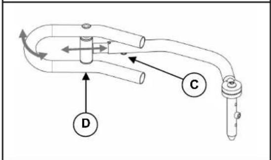
To stabilize the chair's movement characteristics while it is being pushed, the rear wheels can be locked in such a way that the two rear castors move in a parallel track. This means that only the front castors can be used to steer, which enables the chair to be pushed more easily.
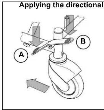
A With the toes of your foot, press downwards on the release lever on either the left or right rear castor (labelled green). Now move the chair till both castors are in parallel with the frame and audibly lock.
B Applying the directional wheel To release the directional wheel function, with the toes of your foot, press downwards on the release lever on either the left or right rear castor (labelled red).
ACCESSORIES
• DOCUMENT HOLDER (B79)
natural_image
Technical line drawing of a mechanical device with no visible text or symbolsA holder can be clipped to the back of the chair to store documents while the patient is being moved. There are two screwholders in the rear frame to attach this. Mount the rail using the two screws supplied so that the open rail ends are outwards. The holder is hung onto the rail ends.
The document holder is only designed to hold a maximum of 4 kg.
- PADS (L04)
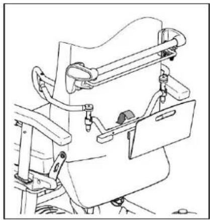
The side pads can be folded away, and you can adjust their height, width and length. The pad retainers can be mounted behind the back section. There are two screw joints in the rear frame to attach the retainer bar.
MOUNTING
Insert the pad into the pad retainer behind the back section in such a way that the head of the adjustable screw (A) fits into the slot in the pad retainer.
FOLDING AWAY
Raise the pad until the head of the adjustable screw (A) comes out of the slot in the pad retainer. Turn the pad outwards or inwards. In so doing, the head of the adjustable screw (A) can be guided to the edge of the pad retainer.
Avoid twisting the tube.
ADJUSTING THE HEIGHT
The sideways height of the pads is fixed by changing the position of the adjusting screw (A) on the vertical tube of the side pad.
ADJUSTING THE WIDTH
You set the width by loosening the screw (B). The sprocket so released can be put into the position you want.
ADJUSTING THE LENGTH
The length of the side pads is set by loosening the screw (C) on the side pad's horizontal tube (3 positions). The screw is then re-tightened.
The pad automatically adjusts to your position on the body side via axle (D).

Ensure that, after the adjustment, only padded parts are in contact with the body, or pressure points can be created.

Before use, please check that all the screws are tight.

Only have assembly and adjustments done by authorised persons.

The manufacturer accepts no liability for damage caused by improper pad adjustments.
• SERUM HOLDER (B52)
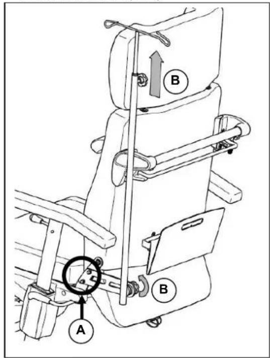
A serum holder can be attached for drips. On the rear strut on the left-hand side, the bracket can be screwed into the pre-drilled holds (A). The adjusting screw (B) can be used to alter the length and angle of the strut.

Ensure that all the screws are tight before use.

Before using the serum holder, ensure that it will not affect giving the drip properly.

If using the serum holder while moving the patient, ensure that all the connecting tubes have no kinks and are safely positioned.

Take care as the serum holder may project beyond the chair and bang into things!

When moving a patient, go more slowly, especially around bends, in order to avoid the serum holder swinging.
• MULTI-PURPOSE HOLDER
The multi-purpose holder on the lower part of the frame can be used to hold e.g. a bottle holder B83 (e.g. for an oxygen cylinder) or the headrest when not in use.
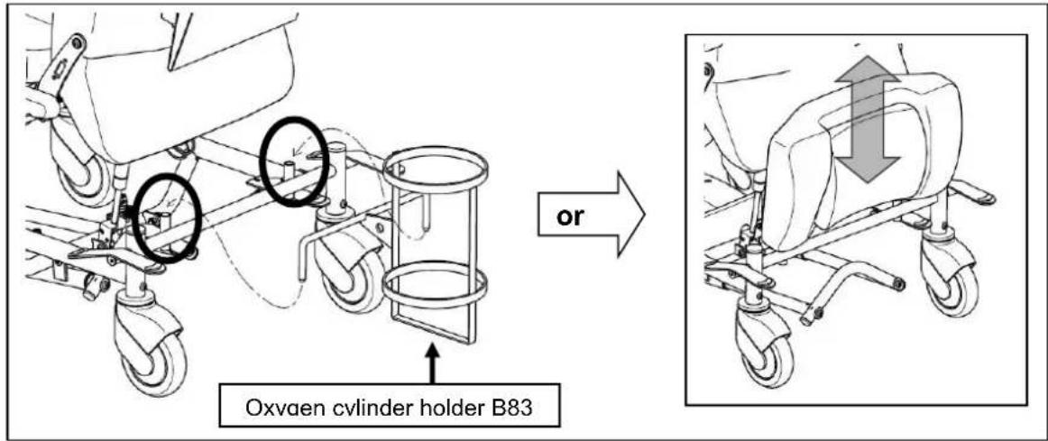

If using the bottle holder while moving the patient, ensure that all the connecting tubes have no kinks and are safely positioned.

When moving a patient, go more slowly, especially around bends.
• ADJUSTABLE LEGREST
There is an option of selecting a legrest that enables the leg position to be raised and set to different angles.
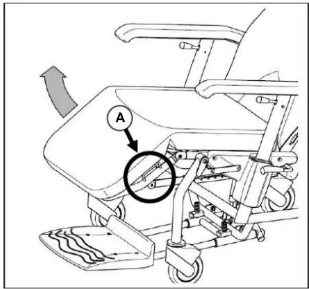
Grip the left- or right-hand handle on the side of the legrest (A) and pull it to the position you want. To lower the legrest back again, pull the legrest to its highest position (horizontal) and the stop notch will release the legrest. It can now be fully lowered once more.
• ADJUSTABLE / WIDENED ARMRESTS
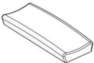
natural_image
Simple line drawing of a rectangular object with rounded ends and a curved top edge (no text or symbols)• TREATMENT TABLE (B12)
A bracket (beneath the armpad) enables a wooden therapy table to be attached which can be adjusted in terms of depth, removed and folded to the side.

natural_image
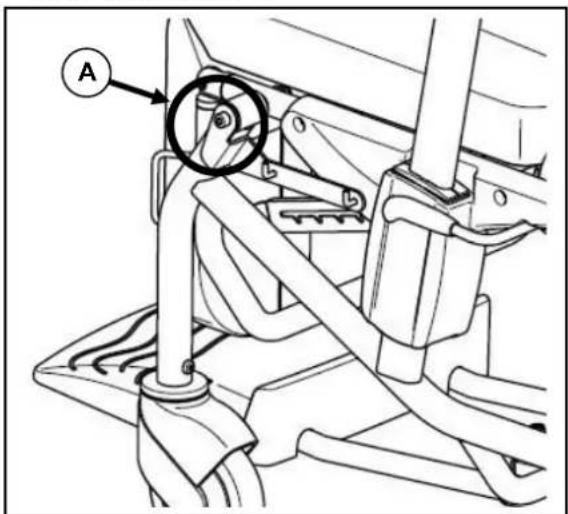
Technical line drawing of a mechanical device showing front and side views (no text or symbols)• URINE BAG HOLDER

A bracket can be attached to the screw joints on the front of the seat frame (A) on the left and/or right of the side frame which will enable a urine bag to be hung on two hooks.

If using the urine bag while moving the patient, ensure that there are no kinks or catches in any of the connecting tubes and the bag.

When moving a patient, go more slowly, especially around bends, in order to avoid the urine bag/s swinging.
TRANSPORT
In order to carry the chair, the snap-bolt on the pneumatic spring attachment on the lower end of the back section can be removed and the back can be folded forwards. If necessary, remove the headrest (if there is one), push the footrest beneath the seat, and lower the legrest (if there is one) as far as it will go. Remove any accessory that is attached if it affects the chair's overall dimensions.

At least two persons should always be involved in carrying it up or down staircases or steps. It should not be carried with the patient in it.

Only lift the chair by fixed parts at the side of the frame. Do not lift it by the armrests or the seat!

When being carried, no persons or objects should be below the chair, to prevent personal injury or damage to the product.

If being carried in a motor vehicle, the recliner should not be used as a seat.

In a motor vehicle, the chair should be made secure using appropriate safety belts attached to the side of the frame.
USING RAMPS
If you are considering ramps for overcoming obstacles, kindly note the following:
This is a product which is essentially designed for use indoors on level routes and surfaces. It should only be used on ramps if they are smooth and no ridges are involved in getting on and off them.

They should not be taken over ramps when somebody is sitting in the chair.
FOR YOUR SAFETY
Please note, depending on the chair's configuration, the following safety hints:

Only use the wheelchair on level surfaces and in indoor areas.

It should not be used on staircases or steps or to pass other obstacles.

Make regular checks to ensure the parking brakes are working properly.

Ensure that there are no objects, obstructions or persons come within the range of adjustment of the back section or the legrest.

Be careful when using sources of fire such as cigarettes, since they can set the seat and back covers alight.

Make sure that the maximum load (140 kg) is not exceeded.

Never open a pneumatic spring as it is under high pressure and you could get hurt!

If the pneumatic springs (if present on the chair) get damaged, stop using the chair. Contact your dealer straight away to get it repaired.

When accessories and attachments are used, the chair's characteristics change.

Only use original accessories, and only use original spare parts for repairs.
MAKING REGULAR CHECKS
Your wheelchair requires regular checks, like any other technical product. The steps to be taken to fully enjoy the advantages of your wheelchair even after protracted use, are described below.
- BEFORE USE
Check the castors for visible damage and/or soiling.
Remove the dirt, since it could impair the functioning of the parking brakes.
If a castor is damaged, please use an authorised workshop to repair it.
• APPROX. EVERY 8 WEEKS
Depending on the frequency of use, kindly check the following:
- Moving parts on the legrest (if there is one)
- Moving parts on the tipping mechanism (if there is one)
- The condition of the covers
- That the armrest adjustment, seat angling and back adjustment are working properly
• APPROX. EVERY 6 MONTHS
Depending on the frequency of use check the following:
- Cleanness
- General condition
- That the screws are tight
- That the steering castors / brakes are working properly
If the rotation resistance is too great, clean the bearings of the steering wheels. If this is insufficient, kindly consult your dealer.
INSPECTION
Depending on the amount of use, in principle we recommend inspections every two years, but at least before usage is resumed. The following checks, at least, must be performed and documented by authorised persons:
- Check the frame parts for plastic deformation and reduced functioning.
- Visual inspection of damage to the paintwork (danger of corrosion)
- Visually check the covers for damage
- Check the castors work properly (run freely, run straight, parking brakes)
- Check that all screws and bolts are tight and well-seated
- The greasing condition of metal joints of movable parts
- Visually check all plastic parts for tears and brittle spots
- Check the legrest works properly (locking, load, deformation, wear and tear caused by weight, adjustment lever)
- Check, including visually, that the pneumatic springs work (incl. the adjusting lever)
• Completeness of the delivery condition - Instruction manual available?
The service must only be confirmed in the service plan when at least the above-mentioned aspects have been checked. If your specialist dealer does not perform the required services, then contact the manufacturer. We shall gladly refer you to authorized specialist dealers in your area.
The manufacturer is not liable for damage caused by lack of inspections or poor inspections.
CARE
Your wheelchair requires regular care to keep it in a pleasant condition. To do this, note the following:

Never use steam or pressure jets.
- COVERS
Clean the covers with a cloth moistened by hot water. You can remove stubborn dirt by washing with a mild commercial detergent. Stains can be removed by using a sponge or a soft brush. Do not use sharp brushes or any other pointed objects for cleaning.

Do not use strong cleaning liquids like solvents, nor use hard brushes.

We do not accept liability for damage caused by the use of improper cleaning liquids.

Do not allow the covers to get too wet.
- PLASTIC PARTS
Clean all plastic parts with commercial plastic cleaners. Take note of any specific product information.
- SURFACE LAYERS
The high quality of the surface layer guarantees optimal protection against corrosion. If the outer layer has been damaged by scratches or otherwise, you can protect the area by applying varnish obtainable from your specialist dealer. Occasional greasing of the movable parts will ensure that you enjoy your wheelchair for a long time.
To guarantee the long-term preservation of your wheelchair, we recommend that you take it to your specialist dealer for inspection every two years. These inspections can be confirmed in the "Service plan" section.

The manufacturer does not accept liability for any damage/injury caused by inadequate servicing and care.
DISINFECTION
Disinfection should only be carried out by a trained hygienist or by someone they appoint. All of the parts can be disinfected by scrubbing. In principle all surfaces of a system or a product must be disinfected before handing it over to a new user or when infections are detected in the user. Then the measures of the Federal Epidemic Law must be applied.

Wear suitable protective clothing because the disinfectants can irritate the skin on contact. For this purpose you should also take note of the product information for the solutions concerned.

You employ unauthorized persons at your own risk.

No liability is accepted by the manufacturer of the wheelchair for damage and injury caused by the improper handling of disinfectants.
All steps taken for disinfection and its components or other accessory parts are recorded in a disinfection report which contains at least the following information with product documentation appended:
Table 2 – Example of a disinfection book
| Date of the disinfection | Reason Specification Substance and concentration | Signature | |
Abbreviations used in column 2 (reason):
V = suspected infection IF = infection case W = repetition I = inspection
We recommend the following disinfectants for scrubbing (based on the list of the Robert Koch Institute, RKI): The current state of the disinfectants included in the RKI list can be ascertained at the Robert Koch Institute (Home page: www.rki.de).
| Active substance | Product name | Laundry disinfection | Surface disinfection (scrubbing-/wiping disinfection) | Disinfection of excretions 1 part sputum or stools + 2 parts diluted solution or 1 part urine + 1 part diluted solution | Area of effectiveness | Manufacturer or Supplier | |||||||
| Sputum | Stools | Urine | |||||||||||
| Diluted solution | Time to take effect | Diluted solution | Time to take effect | Diluted solution | Time to take effect | Diluted solution | Time to take effect | Diluted solution | Time to take effect | ||||
| % | Hr. | % | Hr. | % | Hr. | % | Hr. | % | Hr. | ||||
| Phenol or phenol derivative | Amocid | 1 | 12 | 5 | 6 | 5 | 4 | 5 | 6 | 5 | 2 | A | Lysoform |
| Gevisol | 0,5 | 12 | 5 | 4 | 5 | 4 | 5 | 6 | 5 | 2 | A | Schülke & Mayr | |
| Helipur | 6 | 4 | 6 | 4 | 6 | 6 | 6 | 2 | A | B. Braun | |||
| m-cresylic soap solution (DAB 6) | 1 | 12 | 5 | 4 | A | ||||||||
| Phenol | 1 | 12 | 3 | 2 | A | ||||||||
| Chlorine, organic or inorganic substances with active chlorine | Chloramin-T DAB 9 | 1,5 | 12 | 2,5 | 2 | 5 | 4 | A^1B | |||||
| Clorina | 1,5 | 12 | 2,5 | 2 | 5 | 4 | A^1B | Lysoform | |||||
| Trichlorol | 2 | 12 | 3 | 2 | 6 | 4 | A^1B | Lysoform | |||||
| Per combinations | Apesin AP100 ^2 | 4 | 4 | AB | Tana PROFESSIONAL | ||||||||
| Dismozon pur ^2 | 4 | 1 | AB | Bode Chemie | |||||||||
| Perform ^2 | 3 | 4 | AB | Schülke & Mayr | |||||||||
| Wofesteril ^2 | 2 | 4 | AB | Kesla Pharma | |||||||||
| Active substance | Product name | Laundry disinfection | Surface disinfection (scrubbing-/wiping disinfection) | Disinfection of excretions 1 part sputum or stools + 2 parts diluted solution or 1 part urine + 1 part diluted solution | Area of effectiveness | Manufacturer or Supplier | |||||||
| Sputum | Stools | Urine | |||||||||||
| Diluted solution | Time to take effect | Diluted solution | Time to take effect | Diluted solution | Time to take effect | Diluted solution | Time to take effect | Diluted solution | Time to take effect | ||||
| % | Hr. | % | Hr. | % | Hr. | % | Hr. | % | Hr. | ||||
| Formaldehyde and/or other aldehydes or derivatives | Aldasan 2000 | 4 | 4 | AB | Lysoform | ||||||||
| Antifect FD 10 | 3 | 4 | AB | Schülke & Mayr | |||||||||
| Antiseptica surface disinfection 7 | 3 6 | AB | Antiseptica | ||||||||||
| Apesin AP30 | 5 4 | A | Tana | PROFESSIONAL | |||||||||
| Bacillocid special | 6 4 | AB | Bode Chemie | ||||||||||
| Buraton 10F | 4 | AB | Schülke & Mayr | ||||||||||
| Desomed A 2000 | 3 6 | AB | Desomed | ||||||||||
| Hospital disinfectant cleaner | 8 6 | AB | Dreiturm | ||||||||||
| Desomed Perfekt | 7 4 | AB* | Desomed | ||||||||||
| Formaldehyde-solution (DAB 10), (formaline) | 1,5 | 12 3 | 4 | AB | |||||||||
| Incidin Perfekt | 1 | 12 | 3 | 4 | AB | Ecolab | |||||||
| Incidin Plus | 8 6 | A | Ecolab | ||||||||||
| Kohrsolin | 2 | 12 | 3 | 4 | AB | Bode Chemie | |||||||
| Lysoform | 4 | 12 | 5 | 6 | AB | Lysoform | |||||||
| Lysoformin 2000 | 3 | 12 | 5 | 6 | AB | Lysoform | |||||||
| Lysoformin 2000 | 4 6 | AB | Lysoform | ||||||||||
| Melsept | 2 | 12 | 4 | 6 | AB | B. Braun | |||||||
| Melsitt | 4 | 12 | 10 | 4 | AB | B. Braun | |||||||
| Minutil | 2 | 12 | 6 | 4 | AB | Ecolab | |||||||
| Multidor | 3 | 6 | AB | Ecolab | |||||||||
| Nüscosept | 5 4 | AB | Dr. Nüsken Chemie | ||||||||||
| Optisept | 7 4 | AB* | Dr. Schumacher | ||||||||||
| Pursept-FD | 7 | 4 | AB* | Merz | |||||||||
| Ultrasol F | 3 | 12 | 5 | 4 | AB | Fresenius Kabi | |||||||
| Amphoteric surfactants (amfotensiden) | Tensodur 103 | 2 | 12 | A | MFH Marienfelde | ||||||||
| Lye | Lime-milk^3 | 20 | 6 | A^3B$ | |||||||||
| 1 Not effective against myco-bacteria when service disinfecting, especially in the presence of blood.2 Not suitable for disinfecting blood-contaminated or porous surfaces (e.g. raw wood).3 Useless for tuberculosis; preparation of Lime-milk: 1 part dissolved lime (calcium hydroxide) + 3 parts water.* Checked for effectiveness on viruses in accordance with checking methods of the RKI (Federal Health Reporting 38 (1995) 242).A: Suitable for killing vegetative bacterial germs including myco-bacteria as well as fungi, including fungal spores.B: Suitable for deactivating viruses. | |||||||||||||
Table 3: Disinfectants
Kindly consult your specialist dealer if you have further queries about disinfection; he will gladly assist you.
STORAGE
• Store in a dry place (between + 5 °C and + 45 °C).
• The relative humidity of the air should be between 30% and 70%.
• Air pressure between 700 hPa and 1060 hPa.
- Ensure there is protection against corrosion (e.g. salt water, sea air, sand, dust) by providing sufficient covering or packaging.
- Store all removed parts together in one place (or mark them if necessary) to avoid mixing up with other products when re-assembling.
- No component must be stored with a heavy weight on it.
DISPOSAL
To dispose of the wheelchair, contact a local waste disposal company or return the product to your dealer who, after some hygiene measures, will be able to return it to the manufacturer, who will take dispose of it and recycle it properly, separated into material groups.
Packaging materials can be taken to suitable tips or recycling centers, or to your dealer.
Your dealer will also be able to advise you should you have any queries.
GUARANTEE
Excerpt from the "General business conditions":
(…)
- The terms of the guarantee may differ from country to country. Consult your specialist dealer for the guarantee period for warranty claims.
(…)
Claims are invalid when:
- the agreed condition is only minimally deviated from
- usability is only minimally impaired
- wear and tear is normal
- faults are due to improper assembly or neglected maintenance
- faults are due to improper use
- errors are due to improper handling by customers or their contractual partners or service centers
- damage that arises after the transfer of risk as a result of faulty or negligent handling, excessive demands, unsuitable equipment, faulty assembly or that are due to particular external factors that are not assumed under the contract.
(…)
CONFORMITY
The ALESIA wheelchair complies with the requirements of the European directive:
- 93/42/EEC (Medical Products Directive)
and the product norms:
- (DIN) EN 12182: 2012 (where applicable)
Maintenance plan
| Date | Maintenance | Remarks | Paraph |
| 1/1/2015 | Greasing and general servicing | non | |
Disinfection book
| Date of the disinfection | Reason | Specification | Substance and concentration | Signature |
| Abbreviations used in column 2 (reason):V = Suspected infection IF = Infection case W = Repetition I = Inspection | ||||
TABLE DES MATIÈRES
- Appui-tête (OPTION) 5

- APPUI-TETE (OPTION)
INCLINAISON DU SIÈGE
natural_image
Technical line drawing of a mobile medical mobility device with wheels and control panels (no text or symbols)MANIPULATION ACCOMPAGNATEUR
MANIPULATION PATIENT
natural_image
Technical illustration of a mechanical clamp mechanism (no text or symbols present)natural_image
Technical line drawing of a mechanical assembly with no visible text or symbolsSUSPENSION

RÉGLAGE EN HAUTEUR
natural_image
Simple line drawing of a rectangular object with rounded ends and a flat top (no text or symbols)• TABLE THERAPEUTIQUE (B12)
natural_image
Technical line drawing of a mechanical device showing front and side views (no text or symbols)• SUPPORT DE POCHE A URINE

1 = Rug
2 = Verstelling rugleuning

ZITKANTELING
natural_image
Technical line drawing of a mobile medical rehabilitation device with wheels and control panels, showing no text or symbols
REDIENING BEGELEIDER
natural_image
Mechanical diagram showing two different configurations of a mechanical clamp or lever mechanism, with no visible text or symbols.Rem in vrijloop zetten
natural_image
Technical line drawing of a mechanical device with no visible text or symbolsBEVESTIGEN

HOOGTEVERSTELLING
natural_image
Simple line drawing of a rectangular object with rounded ends and a curved top edge (no text or symbols)• TAFEL(B12)
natural_image
Technical line drawing of a mechanical device showing front and side views (no text or symbols)• URINEZAKHOUDER
- Pelotten (L04)....9
• Serumhalter (B52)....10

• KOPFLEHNE (OPTION)
SITZKANTELUNG

natural_image
Technical illustration of a mechanical device with two views showing a lever mechanism (no text or symbols)natural_image
Technical line drawing of a mechanical assembly with no visible text or symbols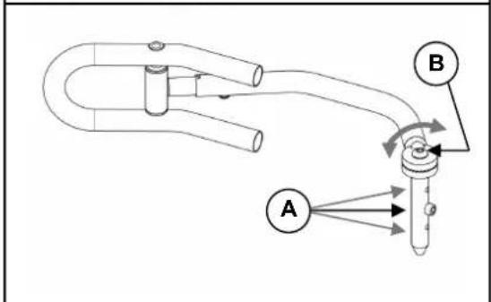
flowchart
graph TD
    A["Component A"] -->|Flow| B["Component B"]
    B -->|Flow| A
    style A fill:#f9f,stroke:#333
    style B fill:#ccf,stroke:#333
EINHÄNGEN
natural_image
Simple line drawing of a rectangular object with rounded ends and a flat top (no text or symbols)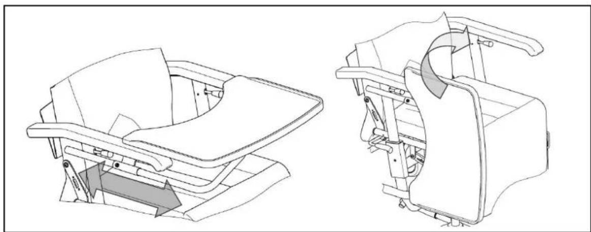
natural_image
Technical line drawing of a mechanical device showing front and side views (no text or symbols)• URINBEUTELHALTER

INCLINAZIONE DEL SEDILE
natural_image
Technical line drawing of a mobile medical mobility device with wheels and control panels, showing assembly steps (no text or symbols)
WSO ACCOMPAGNATORE
natural_image
Mechanical diagram showing two configurations of a mechanical device with lever and handle (no text or symbols)Innesto del freno
natural_image
Technical line drawing of a mechanical assembly with no visible text or symbolsMONTAGGIO

natural_image
Line drawing of a rectangular object with a curved top surface (no text or symbols)- RIPIANO (B12)
natural_image
Technical line drawing of a mechanical device showing front and side views (no text or symbols)• PORTA SACCHETTO DELLE URINE

- (DIN) EN 12182: 2012 (ove applicabile)

natural_image
Technical line drawing of a mobile medical mobility device with wheels and control panels, showing assembly steps (no text or symbols)natural_image
Mechanical diagram showing two configurations of a mechanical device with lever and handle (no text or symbols)natural_image
Technical line drawing of a mechanical assembly with no visible text or symbolsINSERCIÓN

AJUSTE DE LA ALTURA
natural_image
Simple line drawing of a rectangular object with rounded edges and a curved top edge (no text or symbols)• MESA TERAPÉUTICA (B12)
natural_image
Technical line drawing of a mechanical device showing front and side views (no text or symbols)For the good function of the gasspring (backrest inclination) there is mounted a tie-wrap ①.
Do not remove this tie-wrap ①!
• SIEDZENIE

ODCHYLENIE SIEDZENIA
natural_image
Technical line drawing of a mobile medical mobility device with wheels and control panels, showing no text or symbolsABSŁUGA PRZEZ OSOBĘ TOWARZYSZĄCĄ
natural_image
Mechanical diagram showing two configurations of a mechanical device with lever and handle (no text or symbols)natural_image
Technical line drawing of a mechanical assembly with no visible text or symbolsZAKŁADANIE
natural_image
Line drawing of a rectangular object with a curved top surface (no text or symbols)• STÓŁ TERAPEUTYCZNY (B12)
natural_image
Technical line drawing of a car seat assembly showing front and side views (no text or symbols)• UCHWYT DO WORKA NA MOCZ
SKLON SEDÁKU
natural_image
Technical line drawing of a mobile medical mobility device with wheels and control panel (no text or symbols)
UŽITÍ ASISTENTEM
natural_image
Two technical diagrams showing a mechanical device with red and green components, no text or symbols present.natural_image
Technical line drawing of a mechanical assembly with no visible text or symbolsMONTÁŽ
NASTAVENÍ VÝŠKY
natural_image
Line drawing of a rectangular object with a curved top surface (no text or symbols)• OŠETŘOVACÍ STOLEK (B12)
natural_image
Technical line drawing of a mechanical device showing front and side views (no text or symbols)• DRŽÁK SÁČKU NA MOČ

Service registration form
This product (name): ....
was inspected (I), serviced (S), repaired (R) or disinfected (D):
| By (stamp):Kind of work: I / S / R / DDate: | By (stamp):Kind of work: I / S / R / DDate: | By (stamp):Kind of work: I / S / R / DDate: |
| By (stamp):Kind of work: I / S / R / DDate: | By (stamp):Kind of work: I / S / R / DDate: | By (stamp):Kind of work: I / S / R / DDate: |
| By (stamp):Kind of work: I / S / R / DDate: | By (stamp):Kind of work: I / S / R / DDate: | By (stamp):Kind of world: I / S / R / DDate: |
| By (stamp):Kind of work: I / S / R / DDate: | By (stamp):Kind of work: I / S / R / DDate: | By (stamp):Kind of work: I / S / R / DDate: |
| By (stamp):Kind of work: I / S / R / DDate: | By (stamp):Kind of work: I / S /R / DDate: | By (stamp):Kind of work: I / S / R / DDate: |
| By (stamp):Kind of work: I / S / R / DDate: | By (stamp):Kind of work: I / S / R / DDate: | By (stamp):Kind of work: I / S / R / DDate: |

Vermeiren GROUP NV
Vermeirenplein 1 / 15
2920 Kalmthout
BE
website: www.vermeiren.com
- Instructions for specialist dealer
- FR
- PREFACE
- APPLICABILITY
- GENERAL NOTES
- ALESIA COMPONENTS
- TECHNICAL DETAILS
- ASSEMBLY
- - TIE-WRAP
- - SEAT
- - BACK
- • HEADREST (OPTIONAL)
- SEAT ANGLE
- ADJUSTING THE BACK
- USE BY AN ATTENDANT
- BSE BY THE PATIENT
- ARMRESTS
- FOOTPLATE
- Engaging the parking brake
- Releasing the parking brake
- DIRECTIONAL WHEEL
- ACCESSORIES
- MOUNTING
- FOLDING AWAY
- ADJUSTING THE HEIGHT
- ADJUSTING THE WIDTH
- ADJUSTING THE LENGTH
- • MULTI-PURPOSE HOLDER
- • ADJUSTABLE LEGREST
- • ADJUSTABLE / WIDENED ARMRESTS
- • TREATMENT TABLE (B12)
- • URINE BAG HOLDER
- TRANSPORT
- USING RAMPS
- FOR YOUR SAFETY
- MAKING REGULAR CHECKS
- - BEFORE USE
- • APPROX. EVERY 8 WEEKS
- • APPROX. EVERY 6 MONTHS
- INSPECTION
- CARE
- - COVERS
- - PLASTIC PARTS
- - SURFACE LAYERS
- DISINFECTION
- Kindly consult your specialist dealer if you have further queries about disinfection; he will gladly assist you.
- STORAGE
- DISPOSAL
- GUARANTEE
- CONFORMITY
- TABLE DES MATIÈRES
- - APPUI-TETE (OPTION)
- INCLINAISON DU SIÈGE
- MANIPULATION ACCOMPAGNATEUR
- MANIPULATION PATIENT
- SUSPENSION
- RÉGLAGE EN HAUTEUR
- • TABLE THERAPEUTIQUE (B12)
- • SUPPORT DE POCHE A URINE
- ZITKANTELING
- REDIENING BEGELEIDER
- Rem in vrijloop zetten
- BEVESTIGEN
- HOOGTEVERSTELLING
- • TAFEL(B12)
- • URINEZAKHOUDER
- • KOPFLEHNE (OPTION)
- SITZKANTELUNG
- EINHÄNGEN
- INCLINAZIONE DEL SEDILE
- WSO ACCOMPAGNATORE
- Innesto del freno
- MONTAGGIO
- - RIPIANO (B12)
- • PORTA SACCHETTO DELLE URINE
- INSERCIÓN
- AJUSTE DE LA ALTURA
- • MESA TERAPÉUTICA (B12)
- • SIEDZENIE
- ODCHYLENIE SIEDZENIA
- ABSŁUGA PRZEZ OSOBĘ TOWARZYSZĄCĄ
- ZAKŁADANIE
- • STÓŁ TERAPEUTYCZNY (B12)
- • UCHWYT DO WORKA NA MOCZ
- SKLON SEDÁKU
- UŽITÍ ASISTENTEM
- MONTÁŽ
- NASTAVENÍ VÝŠKY
- • OŠETŘOVACÍ STOLEK (B12)
- • DRŽÁK SÁČKU NA MOČ
- Service registration form
Brand : Vermeiren
Model : Alesia
Category : Chair