EEM-AX01 - Electric motor MSW - Free user manual and instructions
Find the device manual for free EEM-AX01 MSW in PDF.

| Product type | Three-phase electric motor |
| Model | MSW-EEM-AX01 |
| Rated voltage | 230/400 V~, 50 Hz |
| Rated power | 2200 W |
| Duty cycle | S1 (continuous duty) |
| Protection class | IP54 |
| Rotation speed | 2865 rpm |
| Efficiency | 85.9 % |
| Power factor (cos φ) | 0.83 |
| Dimensions (L × W × H) | 330 × 170 × 220 mm |
| Weight | 14.25 kg |
| Main materials | Steel, copper, aluminum |
| Cooling | External fan cooling |
| Bearing type | Grease-lubricated ball bearings |
| Mounting | On feet or flange |
| Main functions | Conversion of electrical energy to mechanical energy for driving machinery |
| Maintenance and cleaning | Clean air passages with dry compressed air; check bearings, seals, and insulation resistance |
| Safety instructions | Disconnect before any intervention; use protective equipment; do not touch hot parts |
| Spare parts and repairability | Bearings, seals, fan; rewind by a qualified workshop |
| General information | Nameplate to be checked before installation; storage temperature -15°C to 40°C |
Frequently Asked Questions - EEM-AX01 MSW
User questions about EEM-AX01 MSW
0 question about this device. Answer the ones you know or ask your own.
Ask a new question about this device
Download the instructions for your Electric motor in PDF format for free! Find your manual EEM-AX01 - MSW and take your electronic device back in hand. On this page are published all the documents necessary for the use of your device. EEM-AX01 by MSW.
USER MANUAL EEM-AX01 MSW
This User Manual has been translated using machine translation. We have made every effort to ensure the translation is accurate, but please note that automated translations are not perfect and are not meant to replace human translators. The official version of the User Manual is in English. Any differences between the translated version and the original English are not legally binding. If you have any questions about the accuracy of the translation, please refer to the English version, which is the official reference. More language versions are available upon request via info@expondo.com.
Technical data
| Parameter description Parameter value | |
| Product name | Electric engine |
| Model | MSW-EEM-AX01 |
| Rated voltage [V~] / frequency [Hz] | 230|400 / 50 |
| Rated power [W] | 2200 |
| Work type | S1 |
| Protection rating IP | IP54 |
| Rotation speed [rpm] | 2865 |
| Efficiency [%] | 85.9 |
| Power factor [cos Φ] | 0.83 |
| Dimensions [width x depth x height; mm] | 330 x 170 x 220 |
| Weight [kg] | 14.25 |
These instructions must be read carefully to ensure safe and proper installation, operation, and maintenance of the motor. The specified safety instructions must be paid attention and fully followed.
The following symbols are taken part in the operating manual.

WARNING
This symbol indicates a warning of dangerous situations in terms of life and property safety
ELECTRIC SHOCK HAZARD
This symbol indicates a warning against an electric shock hazard. The symbol means that caution should be taken against the risk of electric shock and necessary measures should be taken.
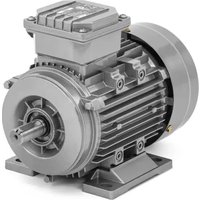
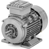
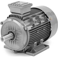
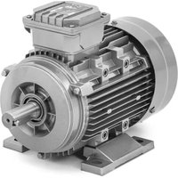
This device is an electric motor that converts electric energy into mechanical energy. Motor is designed for a wide range of drive applications both for line operation as well as in conjunction with frequency converters.
The motor has not been designed for hazardous area applications.
General Safety Rules:
Please read the operating manual of motor for proper storage, installation, and operation.
Mechanical and electrical installation and maintenance shall be done by qualified technicians!
For your personal safety and to prevent material damage when working on the motor, always observe the safety instructions and the following safety rules.
- Disconnect the system. Disconnect the auxiliary circuits, for example anti-condensation heating.
■ Prevent reconnection.
■ Make sure that the equipment is at zero voltage.
■ Ground and short-circuit the terminals.
■ Cover or isolate nearby components that are still live.
To energize the system, apply the measures in reverse order.
Electric motors have hot surfaces, contain live parts and dangerous rotating parts. Fatal or severe injuries and substantial material damage can occur if the required covers are removed or if the motors are not handled, operated or maintained properly.
LIFTING AND STORAGE
Please check the delivered product if any damages can exist in transportation process.
Motors above 25 kg weight have lifting lugs or eye bolts. The actual weight of motors is shown on the nameplate.
■ Only the main lifting lugs or eyebolts of the motor should be used for lifting the motor.
■ Use all the lifting eyes on the motors.
■ Don't use damaged lifting lug.
Shocks, falls, and humidity should be avoided during transportation
During storage, the following conditions must be satisfied.
- The storage rooms must provide protection against extreme weather conditions. They must be dry, free from dust, frost, and vibration, and well ventilated.
■ Temperature shall be between -15^ and 40^ .
■ Motor shaft shall be rotated by hand at least once per year. - Protect motors from direct effect of sun and from gases that have corrosion impact on motors.
■ Unprotected machined surfaces (shaft-ends and flanges) should be treated against corrosion. - Open any condensation drain holes to drain the condensation (<6 months).
If an anti-condensation heater is provided, switch it on during the machine stoppages.
COMMISSIONING
Immediately upon receipt, check the motor for external damage (e.g. shaft-ends and flanges and painted surfaces) and if found, inform the forwarding agent without delay. Check all nameplate data, especially voltage and winding connection to ensure that the motor protection and connection will be properly done.
Checking The Insulation Resistance
Motor winding insulation resistance shall be measured prior to starting the motor, if the winding is too damp.
■ Only appropriately trained personnel may carry out this work.
■ Before starting commissioning, install all covers that are designed to prevent active or rotating parts from being touched.
- If any power cables are connected, check to make sure line supply voltage cannot be connected.
- Once you have measured the insulation resistance, discharge the winding by connecting it to the ground potential.
■ Measurement of insulation resistance should be performed while the motor is not in operation.
If the measurements are performed at winding temperatures not equal to 25 °C , convert the measured value to the reference temperature of 25 °C to be able to compare the values with the table below.
■ The insulation resistance halves every time the temperature rises by 10 °K.
■ The resistance doubles every time the temperature falls by 10 °K .
Insulation resistance, corrected to 25^ C, must be higher than the reference value given below.
If the reference resistance value is not attained, the winding is too damp and must be oven dried.
The oven temperature should be 90^ C - 100^ C for 12 hours.
| Insulation Resistance of The Stator Winding at 25 °C | |
| Measuring circuit voltage | 500 V |
| Minimum insulation resistance for new, cleaned or repaired windings | 100 MΩ |
MECHANICAL INSTALLATION
Safety Considerations
- The machine is intended for installation and use by qualified personnel, familiar with health and safety requirements and national legislation.
■ Safety equipment necessary for the prevention of accidents at the installation and operating site must be provided in accordance with local regulations. - The temperature of the outer casing of the motor may be too hot to touch during normal operation and especially after shut-down.
■ Be aware of rotating parts of the motor. - Do not open terminal boxes while energized.
Before start-up, please check that:
- Condensation drain holes are always located at the lowest point of the motor!
■ Connect the motor corresponding to the specified direction of rotation.
■ Ensure that all seals and sealing surfaces are undamaged and clean.
When aligning and fastening the motor, please bear the following in mind:
- The motor shall be mounted on a base, which is rigid enough to prevent distortion and vibration.
■ Feet and flanges must be fastened securely.
■ Avoid using rigid coupling measures. - The motors must be carefully aligned. Incorrect alignment can lead to beating failure, vibration, even shaft fracture.
- Coupling halves and pulleys must be fitted on the shaft by using suitable equipment and tools which do not damage the bearings and seals. Never fit a coupling half or pulley by hammering or by removing it using a lever pressed against the body of the motor
■ Excessive belt tension will damage bearings and can cause shaft damage.
If a belt drive is used, make sure that the driving and the driven pulleys are correctly aligned. - The motor should be mounted in such a way that the cooling air should flow to and away from the motor without obstruction.
- Do not exceed permissible loading values for bearings as stated in the product catalogues.
As standard, balancing of the motor has been carried out using half key.
Coupling halves or pulleys must be balanced after machining the keyways. Balancing must be done in accordance with the balancing method specified for the motor.
When aligning the motor to the load, it must be ensured that the couplings used are on the same axis. In addition, at least 2-5 mm axial clearance is required between the couplings.
If the belt pulley system is used when connecting the motor to the load, care must be taken to ensure that the pulleys are in parallel axes and that the belt is not too tight or too loose.
ELECTRICAL INSTALLATION AND OPERATION CONDITIONS

Before installation, check motor specifications from nameplate if they fit the requirements and specification of voltage and frequency.
Measure the insulation resistance between windings and housing.
Note the following safety information before connecting-up the motor:
- Only qualified and trained personnel should carry out work on the motor while it is stationary.
- Disconnect the motor from the power supply and take measures to prevent it being reconnected. This also applies to auxiliary circuits.
■ Check that the motor really is in a no-voltage condition.
■ Establish a safe protective conductor connection before starting any work.
It must be ensured that there are no foreign bodies, dirt, or moisture in the terminal box.
- Keep the inside of the terminal box clean and free from trimmed-off ends of wire.
- Close any additional open cable entries with O-rings or suitable flat gaskets, the terminal box itself must be sealed so that it is dust and watertight using the original seal.
■ When performing a test run, secure the feather keys without output elements.
- Earthing must be carried out according to local regulations before the machine is connected to the supply voltage.
The losses occurring during no-load operation in single phase motors are much more than the losses in nominal load operation. Therefore, single phase motors must not be run no-load for a long time.
Terminals and Direction of Rotation
The standard motors are suitable for clockwise and counterclockwise rotation.
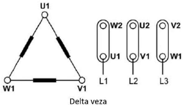
In three phase motor, when the power cables L1, L2, L3 are connected to U1, V1, W1 respectively, the three phase motor shaft turns in clockwise direction (looking at the shaft from drive side). If two of the power cables are interchanged then the resulting direction of rotation is counterclockwise.
In single phase motor, when the power cables L1 and N are connected to U1 and U2 respectively, the single phase motor shaft turns in clockwise direction (looking at the shaft from drive side). If the winding ends (Z1 and Z2) of the auxiliary winding are replaced then the resulting direction of rotation is counterclockwise.
In addition to the main winding terminals and earthing terminal, the terminal box can also contain connections for thermistors, heating elements or other auxiliary devices.
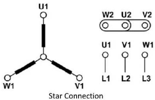
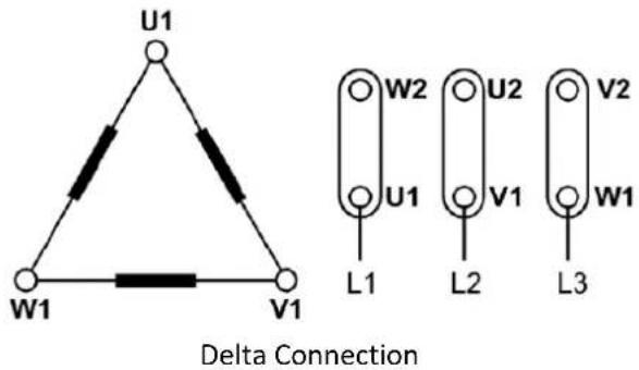
The terminal box on standard single speed three phase motors normally contains six winding terminals and at least one earthing terminal. This enables the use of DOL (direct online) or Y/D (star delta) starting. The standard single-phase motor terminal box contains four winding terminals (two main winding ends and two auxiliary winding ends), two capacitor terminals (CR) and at least one ground terminal.
The three phase motors shall be connected in star or delta according to rated voltage given in their nameplate and the network voltage that they will be connected to. For phase to phase 400 V supply, the motors with 230/400V nameplate values shall be connected in star (Y) and the motors with 400/690V nameplate values shall be connected in delta ( ). The connection types given below should be applied for single-phase motors, depending on the direction of rotation.
Terminal Connection For Single Speed Motor:
Troubleshooting For Three Phase Motors
Motor service and any troubleshooting must be handled by qualified persons who have proper tools and equipment. Before rectifying any faults, please read the information in the section titled Safety Information.
| Defect | Cause | Solution |
| Motor does not start | Blown fuses | Replace the fuses with correct one with rated value |
| Incorrect line connections | Check the connections | |
| Motor overloaded | Decrease the load | |
| Mechanical damage | Check whether the motor and drive rotate freely | |
| One of the phases may be open | Check the phases on the line | |
| Motor stalls | One of the phases may be open. | Check if there is a broken phase on the lines |
| Improper motor selection. | Change the type or size. Contact the device's supplier or designer. | |
| Overload. | Decrease the load | |
| Low voltage. | Check whether the voltage stated on the rating plate is maintained. Check the connection. | |
| Open power supply or control circuit. | Blown fuses, check the load relay, stator and control buttons. | |
| Motor takes a long time to gain speed | Low voltage | Check the circuit capacity and power source |
| Over loading | Decrease the load | |
| Rotor damaged | Replace the rotor | |
| Incorrect converter settings | Correct the settings | |
| Motor runs and die down | Power failure | Check for a loose connection in the power supply line, fuses and control. |
| Wrong rotation direction | Wrong sequence of phases | Reverse connections at terminals |
| Motor heats up excessively | Motor overloaded Decrease the load | |
| Low voltage | Adjust motor to supply voltage | |
| Ambient temperature is too high | Observe the permitted temperature range, decrease the load if necessary or Check the insulation class and use appropriate special motor | |
| Insufficient cooling | Provide air cooling supply, clean cooling air passages | |
| Bearing failure | Replace the bearings | |
| Unbalanced voltage | Check the circuit | |
| Short circuit in motor's winding | Rewind the motor | |
| One of the phases may be open | Check the phases on the line | |
| Broken ventilator or lack of ventilator | Check the ventilator | |
| Noisy operation | One of the phases may be open | Check the phases on the line |
| Air gap not uniform | Check the bearing fits | |
| Fan rubbing end shield or fan cover | Check the fan mounting | |
| Broken ventilator | Replace the ventilator | |
| Incorrect coupling of the motor with the driven machine | Adjust the motor orientation and belt tension | |
| Broken rotor bar | Replace the rotor | |
Faults During Operation
Deviations from conditions during normal operation, such as an increase in power consumption, temperatures or vibrations, unusual noises or odours, tripping of monitoring devices, etc., indicate that the motor is not functioning properly. This can cause faults which can result in eventual or immediate death, severe injury, or material damage.
■ Immediately inform the maintenance personnel.
- If you are in doubt, immediately switch off the motor, being sure to observe the system-specific safety conditions.
INSPECTION
Safety Instructions
■ Before starting work on the motors, make sure that the plant or system has been disconnected in a manner that is compliant with the appropriate specifications and regulations.
In addition to the main currents, make sure that supplementary and auxiliary circuits, particularly in heating devices, are also disconnected.
- A motor with frequency converter supply may energize even if the motor is at standstill.
- Certain parts of the motor may reach temperatures above 50°C. Physical contact with the motor could result in burn injuries! Check the temperature of parts before touching them.
General Inspection
Inspect the motor at regular intervals, at least once a year. The frequency of checks depends on, for example, the humidity level of the ambient air and on the local weather conditions. This can initially be determined experimentally and must then be strictly adhered to.
Keep the motor clean and ensure free ventilation airflow. If the motor is used in a dusty environment, the ventilation system must be regularly checked and cleaned.
- Check the condition of shaft seals and replace if necessary.
- Check the condition of connections and mounting and assembly bolts.
- Check the bearing condition by listening for any unusual noise, vibration measurement, bearing temperature, inspection of spent grease.
- Check if the electrical parameters are maintained.
- Check if the winding insulation resistances are sufficiently high.
- Check if the cables and insulating parts and components are in a good condition and are not discoloured.
Immediately correct any impermissible deviations that are determined in the inspection.
If the paint is damaged, it must be repaired to protect the unit against corrosion.
Pay special attention to bearings when their calculated rated lifetime is coming to an end.
When signs of wear are noticed, dismantle the motor, check the parts, and replace if necessary. When bearings are changed, replacement bearings must be of the same type as those originally fitted. The shaft seals must be replaced with seals of the same quality and characteristics as the originals when changing bearings.
MAINTENANCE AND REPAIR
Cleaning
Regularly clean the cooling air passages through which the ambient air flows, e.g. using dry compressed air.
Particularly when carrying out cleaning using compressed air, make sure you use suitable safety wear.
If there are condensate drain holes present, these must be opened at regular intervals, depending on climatic conditions. To maintain the degree of protection, any condensation drain holes need to be closed.
Instructions for Repair
Only appropriately qualified persons should be deployed to commission and operate equipment. Qualified persons, as far as the safety instructions specified in this manual are concerned, are those who have the necessary authorization to commission, ground and identify equipment, systems and circuits in accordance with the relevant safety standards.
Before you begin working on the three-phase motor, in particular before you open the covers of active parts, make sure that the three-phase motor or system is properly isolated from the supply.
Replacing Bearings
Special care should be taken with the bearings. These must be removed using pullers and fitted by heating or using special tools for the purpose.
Do not reuse bearings that have been removed.
Rewinding
Rewinding should always be carried out by qualified repair shops.
Assembly
If possible, assemble the motor on an alignment plate.
Avoid damaging the windings protruding out of the stator enclosure when fitting the end Shield Take care not to damage the cable jacket. Tightening torques must be adapted to suit the type of cable jacket material in use.
Shaft sealing should be assembled to the right position without any damage.
- Check the terminal box seals and if required, replace.
- Do not forget the foam cover in the cable entry (seal all holes completely and prevent cables from touching any sharp edges).
■ Repair any damage to the paint (also on screws/bolts). - Check the tightening torques of all screws, as well as those of screws which have not been unscrewed.
DISPOSAL
Dismantle the motor using the general procedures commonly used in mechanical engineering. Dispose of the separated components according to local regulations or via a specialist disposal company.

KONSERWACJA I NAPRAWA
Czyszczenie
MECHANICKÁ INSTALACE
MECHANISCHE INSTALLATIE
VEDLIKEHOLD OG REPARASJON
Rengjøring
For the disposal of the device please consider and act according to the national and local rules and regulations.
CONTACT
expondo Polska sp. z o.o. sp. k.