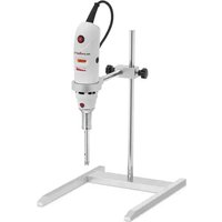
SBS-UH-210 - Food processor STEINBERG - Free user manual and instructions
Find the device manual for free SBS-UH-210 STEINBERG in PDF.


| Product type | Rotor-stator homogenizer (food processor) |
| Brand | Steinberg |
| Model | SBS-UH-210 |
| Power | 180 W |
| Voltage / Frequency | 220-240 V / 50-60 Hz |
| Dimensions (L x W x H) | 23 x 30 x 37 cm |
| Weight | 2.3 kg |
| Probe material | 316L stainless steel and PTFE |
| Variable speed | Yes, via speed switch |
| Minimum immersion depth | 20 mm below liquid level |
| Main function | Homogenization: particle breakdown for uniform mixing |
| Maintenance | Clean with a damp cloth; disassemble and clean the rotor/stator probe after each use with a mild detergent |
| Safety | Do not use dry; avoid explosive atmospheres; check voltage compatibility |
| Sterilization | Autoclavable or hot air sterilization (160°C) |
| Included accessories | Stand, clamp, fixing screw, assembly keys |
| Recycling instructions | Do not dispose of with household waste; take to a WEEE collection point |
Frequently Asked Questions - SBS-UH-210 STEINBERG
User questions about SBS-UH-210 STEINBERG
0 question about this device. Answer the ones you know or ask your own.
Ask a new question about this device
Download the instructions for your Food processor in PDF format for free! Find your manual SBS-UH-210 - STEINBERG and take your electronic device back in hand. On this page are published all the documents necessary for the use of your device. SBS-UH-210 by STEINBERG.
USER MANUAL SBS-UH-210 STEINBERG
natural_image
Industrial machine with tripod base and metal frame, no visible text or symbolsEinrichtung

natural_image
Technical line drawing of a soldering iron with a handle and socket (no text or symbols)This User Manual has been translated using machine translation. We have made every effort to ensure the translation is accurate, but please note that automated translations are not perfect and are not meant to replace human translators. The official version of the User Manual is in English. Any differences between the translated version and the original English are not legally binding. If you have any questions about the accuracy of the translation, please refer to the English version, which is the official reference.
Technical data
| Parameter description | Parameter value |
| Product name | Homogenizer |
| Model | SBS-UH-210 |
| Power [W] | 180 |
| Voltage [V] / Frequency [Hz] | 220-240 / 50-60 |
| Input power [W] | 160 |
| Dimensions [width x length x height; cm] | 23 x 30 x 37 |
| Weight [kg] | 2.3 |
Purpose
The homogenizer is used to create a uniform and stable mixture by breaking down large particles, droplets, or components of a substance into smaller, more evenly distributed ones. This process is essential in many industries, including food, pharmaceuticals, cosmetics, and biotechnology, to achieve consistent texture, stability, and composition in products.
Product Overview
natural_image
Industrial machine with tripod base and metal frame, no visible text or symbolsInstallation
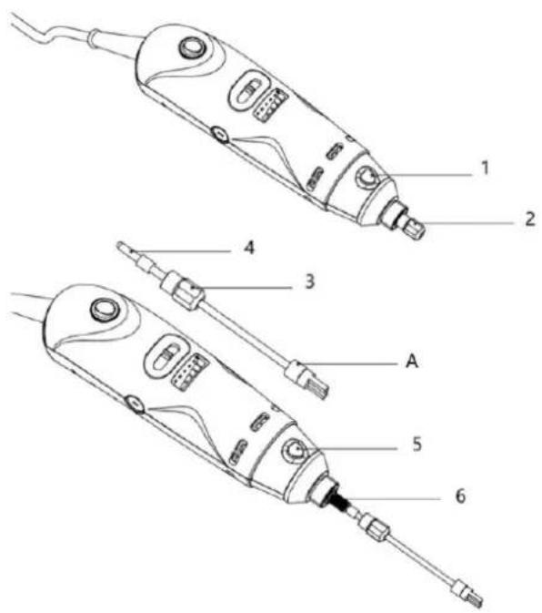
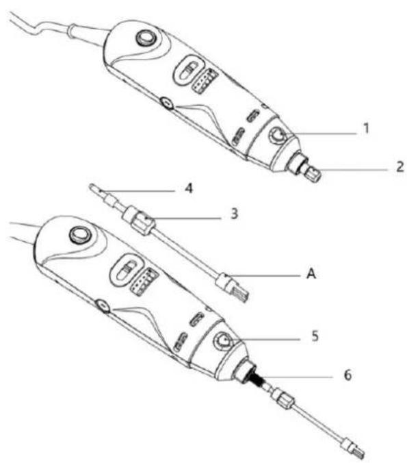
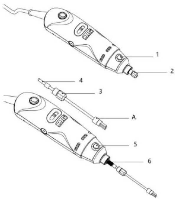
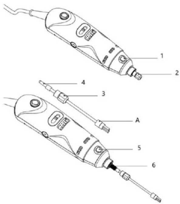
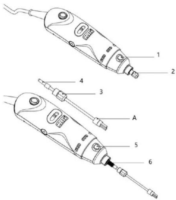
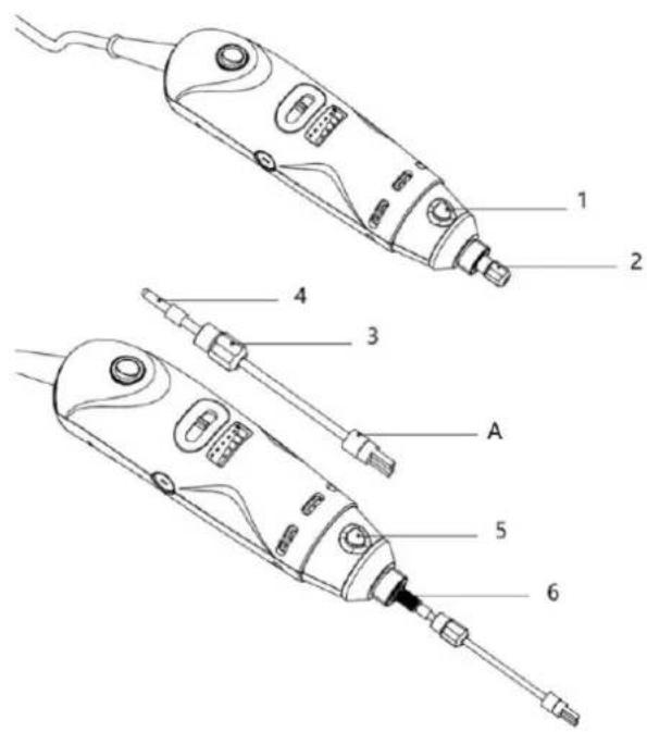
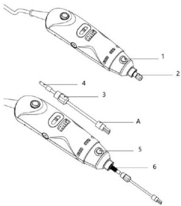
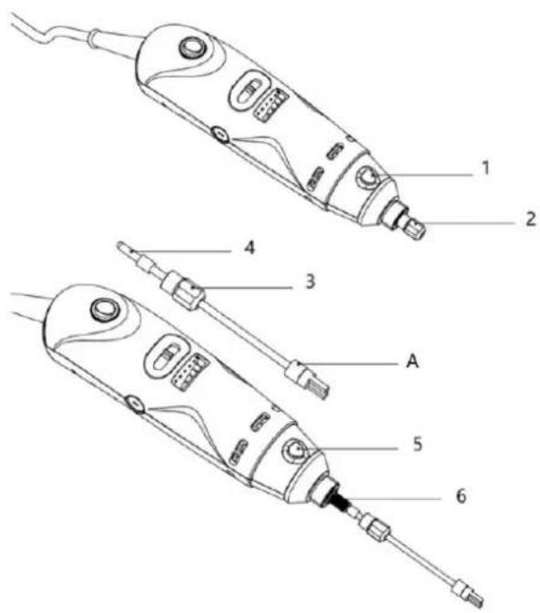
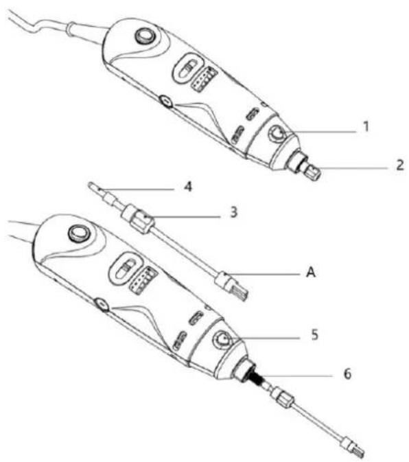
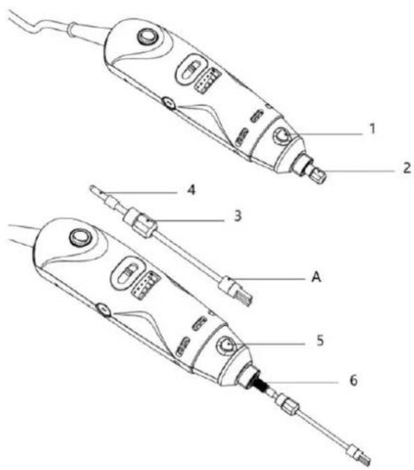
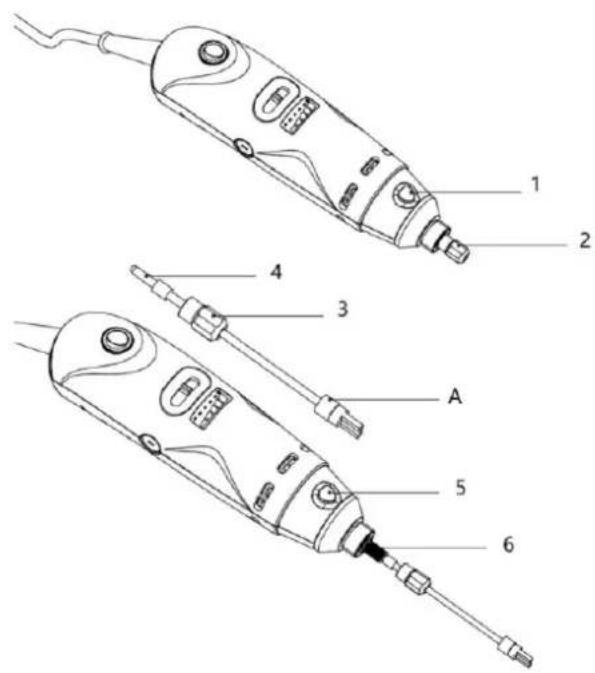
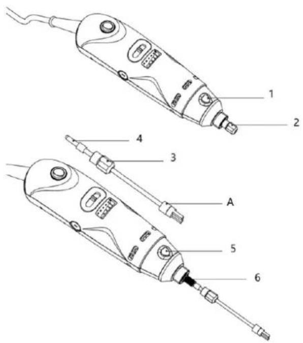
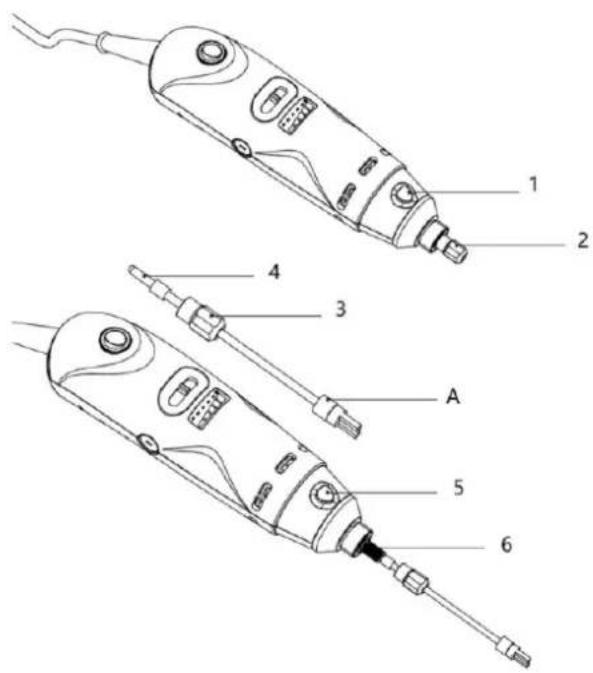
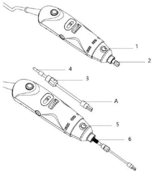
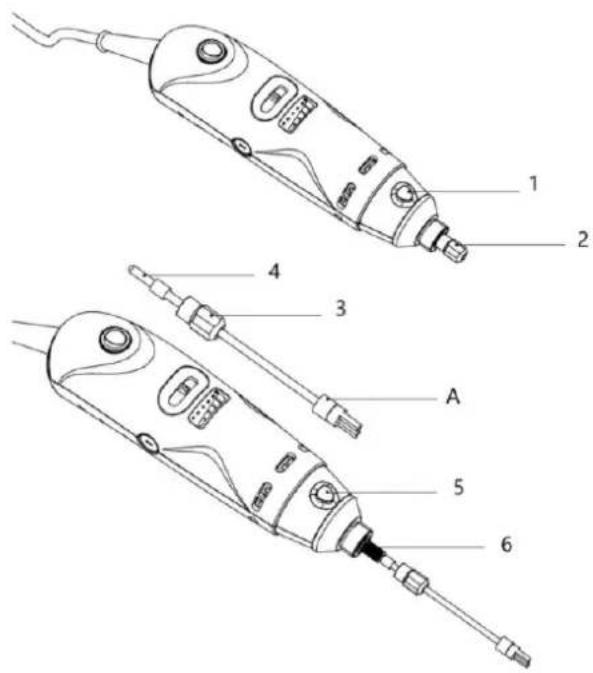
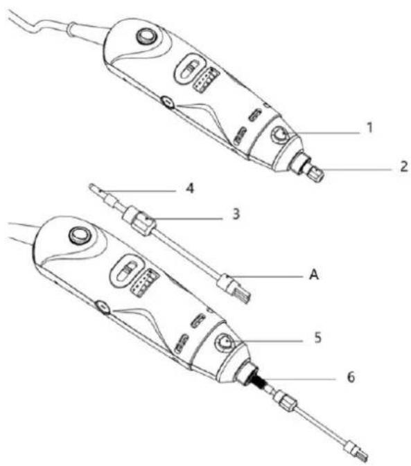
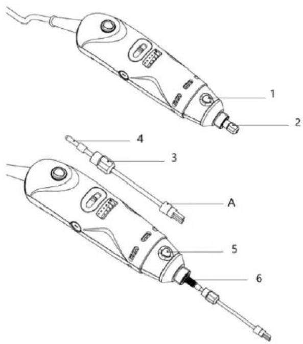
- Press down on the Shaft Lock.
- Unscrew the lock nut.
- Insert the lock nut after removing the silicon ring.
-
Put the silicone ring back after inserting the locknut.
-
Press down on the Shaft Lock.
- Insert the rotor unit into the drive unit and screw the locknut tight.
Remarks:
- In Step 6 Insert the rotor unit into the drive unit so that it is fully seated against the drive unit. Hand tight the locknut while holding the rotor unit in place.
• A refers to PTFE shaft sleeve.
natural_image
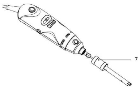
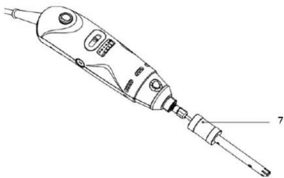
Line drawing of a soldering iron with a handle and connector (no text or symbols)- Screw the Stator unit onto the assembly as shown and tighten properly

NOTE
- Inspect the device and probe for damage. Contact the manufacturer for replacements if needed.
- Set up the stand in a stable, spacious area on a clean, dry, fireproof surface.
• Ensure the stand does not move during operation. - Ensure electrical safety to prevent fire, shock, or injury. Match supply voltage to the nameplate.
- Avoid using the instrument in explosive atmospheres or with hazardous substances.
• Prevent water splashes and avoid humid environments.
• Ensure the nameplate voltage matches the supply voltage. - Beware of electrostatic discharge between the medium and homogenizer probe.
- Do not let the probe touch glass vessels.
• Assemble and tighten the probe properly.
• Never run the probe dry to avoid damaging the PTFE sleeve. - Keep ventilation slots clear and avoid placing powders near airflow from the ventilation holes.
- At high speed, the ventilation hole generates airflow. Keep powders or light items away, as they may be blown away.
• Only trained staff should operate the instrument.
• Use manufacturer-provided probes for safe operation. - If unusual, grinding, or loud noise occurs, turn off the device and replace the probe. Contact support if the issue persists.
Operation
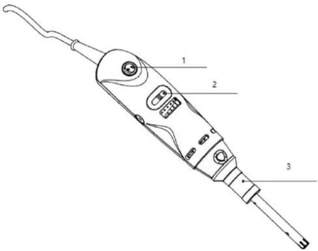
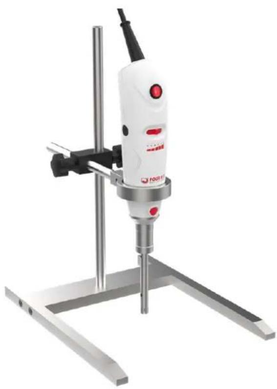
1- Power Switch
2- Speed Switch
3- Rotor/Stator Probe
- Ensure the nameplate voltage matches the supply voltage.
- Tightly secure the rotor/stator probe before use to prevent separation at high speeds.
- Ensure the probe is immersed at least 20 mm below the liquid level, with a 10 mm gap from the bottom. The optimal immersion is approximately 2/3 below the liquid surface and 1/3 above the bottom of the container.
- Set the device to the lowest speed before switching it on.
- Gradually increase the speed to the desired level.
- Lower the speed if the medium splashes out.
Assembly of Clamp and Stand
- Use the screws provided to secure the left and right stand supports onto the stand base.
- Screw the Stand Rod onto the stand base.
- As shown in the picture below, insert the Cross Clamp Block onto the Stand Rod and secure it in the desired position by tightening the screw near the Stand Rod. Also, insert the Clamp Rod into the Cross Clamp Block (as shown in the figure) and secure in a desired position by tightening the screw near the Clamp Rod.
- Secure the Clamp onto the Clamp Rod using the screw provided in the kit.
- Secure the rotor-stator homogenizer into the clamp and tighten it before use.
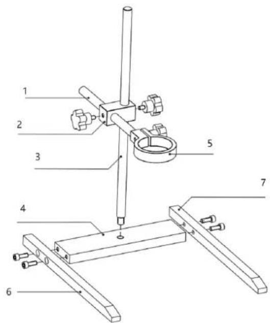
1- clamp Rod
2- Cross Clamp Block
3- Stand Rod
4- Stand Base
5- Clamp
6- Left Stand Support
7- Right Stand Support
Cleaning & Maintenance
- Clean the instrument with a wet cloth; avoid corrosive liquids or detergents.
• Disassemble and clean the rotor/stator probe after each use with mild detergent. - If sterilization isn't needed, use an appropriate solvent between similar samples to clean the probe without disassembly. For example, if you're homogenizing multiple samples with the same or similar composition, you could simply use the same solvent to remove most of the residue between samples. This should be done as soon as possible after use to avoid materials drying on to the rotor/stator probe. You will not have to dismantle the unit for this type of cleaning. Clean promptly to prevent residue buildup.
- The stainless steel probe may corrode with certain chemicals, so use safe solvents like alcohol, water, or mild detergent.
- The drive unit is maintenance-free, but carbon brushes wear down over time. Contact your supplier for replacements and disconnect power before replacing. Do not replace brushes if the unit is under warranty—contact the manufacturer for support.
Sterilization of Rotor/Stator Probes
• Use germicidal solutions (e.g., formalin, phenol, alcohol) for disinfection.
- Remove disinfectant residues with sterilized water and dry to avoid contamination and corrosion.
• Ensure all chemicals used are compatible with SS 316L and PTFE materials. - For thorough sterilization, the rotor/stator probe can be autoclaved. Ensure the probe is cleaned beforehand to avoid baking any residue. Hot air sterilization (at 160°C) is an alternative to autoclaving.
Disposing of Used Devices
Do not dispose of this device in municipal waste systems. Hand it over to an electric and electrical device recycling and collection point. Check the symbol on the product, instruction manual and packaging. The plastics used to construct the device can be recycled in accordance with their markings. By choosing to recycle you are making a significant contribution to the protection of our environment.
Contact local authorities for information on your local recycling facility.

natural_image
Industrial machine with tripod base and metal frame, no visible text or symbolsInstalacja
natural_image
Technical line drawing of a soldering iron with a handle and connector (no text or symbols)natural_image
Industrial machine with tripod base and metal frame, no visible text or symbolsInstalace
natural_image
Technical line drawing of a soldering iron with a handle and connector (no text or symbols)natural_image
Industrial machine with tripod base and metal frame, no visible text or symbolsInstallation
natural_image
Line drawing of a soldering iron with a probe inserted into a terminal (no text or symbols)natural_image
Industrial machine with tripod base and metal frame, no visible text or symbolsInstallazione
natural_image
Technical line drawing of a soldering iron with a handle and socket (no text or symbols)natural_image
Industrial machine with tripod base and metal frame, no visible text or symbolsInstalación
natural_image
Technical line drawing of a soldering iron with labeled component (no text or symbols present)natural_image
Industrial machine with tripod base and metal frame, no visible text or symbolsTelepítés
natural_image
Line drawing of a soldering iron with a handle and connector (no text or symbols)natural_image
Industrial machine with tripod base and metal frame, no visible text or symbolsInstallation
natural_image
Line drawing of a soldering iron with a handle and connector (no text or symbols)natural_image
Industrial machine with tripod base and metal frame, no visible text or symbolsAsennus
natural_image
Technical line drawing of a soldering iron with a handle and connector (no text or symbols)1- c lampun varsi
2- Cross Clamp Block
3- Stand Rod
4- Jalusta
5- Puristin
6- Vasemman jalustan tuki
7- Oikean jalustan tuki
Puhdistus ja huolto
natural_image
Industrial machine with tripod base and metal frame, no visible text or symbolsInstallatie
natural_image
Technical line drawing of a soldering iron with a handle and connector (no text or symbols)natural_image
Industrial machine with tripod base and metal frame, no visible text or symbolsInstallasjon
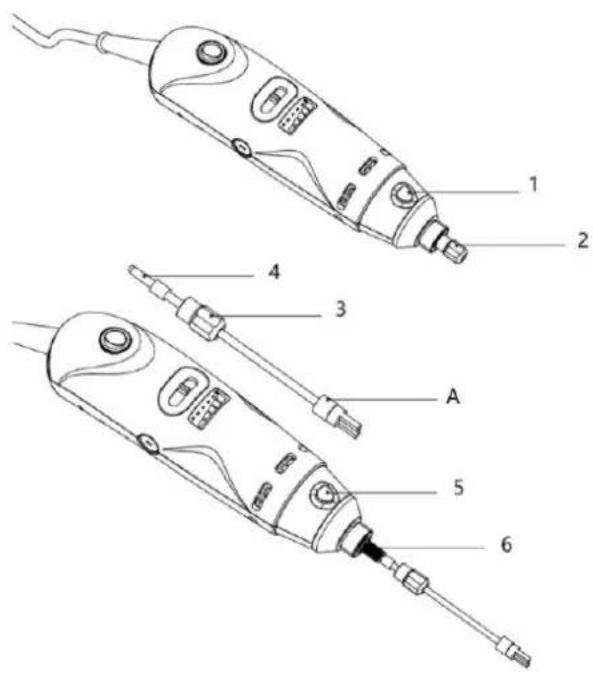
- Trykk ned aksellåsen.
- Skru av läsemutteren.
- Sett inn läsemutteren etter at du har fjernet silikonringen.
-
Sett silikonringen tilbake etter at du har satt inn läsemutteren.
-
Trykk ned aksellåsen.
-
Sett rotorenheten inn i drivenheten og skru til låsemutteren.
Merknader:
natural_image
Technical line drawing of a soldering iron with a handle and connector (no text or symbols)1- Strømbryter
2- Hastighetsbryter
3- Rotor/statorsonde
natural_image
Industrial machine with tripod base and metal frame, no visible text or symbolsInstallation
natural_image
Technical line drawing of a soldering iron with a handle and socket (no text or symbols)1- Strömbrytare
2- Hastighetsomkopplare
3- Rotor/statorprob
natural_image
Industrial machine with tripod base and metal frame, no visible text or symbolsInstalação
natural_image
Technical line drawing of a soldering iron with labeled component (no text or symbols present)1- Interruptor de energia
2- Interruptor de velocidade
3- Sonda de rotor/estator
1- Haste de lâmpada c
2- Bloco de grampo cruzado
3- Suporte de vara
4- Base de suporte
5- Grampo
6- Suporte de suporte esquerdo
7- Suporte de suporte direito
natural_image
Industrial machine with tripod base and metal frame, no visible text or symbolsInštalácia
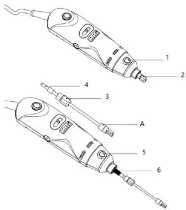
- Stlačte nadol zámok hriadel'a.
- Odskrutkujte poistnú maticu.
- Po odstránení silikónového krúžku vložte poistnú maticu.
-
Po vložení poistnej matice vložte silikónový krúžok spät.
-
Stlačte nadol zámok hriadel'a.
- Vložte rotorovú jednotku do hnacej jednotky a pevne zaskrutkujte poistnú maticu.
Poznámky:
natural_image
Technical line drawing of a soldering iron with a handle and screwdriver (no text or symbols)1- Vypínač napájania
2- Prepínač rýchlosti
3- Sonda rotora/statora
natural_image
Industrial machine with tripod base and metal frame, no visible text or symbolsМонтаж
natural_image
Technical line drawing of a soldering iron with a handle and connector (no text or symbols)natural_image
Industrial machine with tripod base and metal frame, no visible text or symbolsΕγκατάσταση
natural_image
Technical line drawing of a soldering iron with a handle and connector (no text or symbols)natural_image
Industrial drill press machine with metal frame and tripod base (no visible text or symbols)Montaža
- Pritisnite osovinsku bravu.
- Odvijte protumaticu.
- Umetnite protumaticu nakon uklanjanja silikonskog prstena.
- Vratite silikonski prsten nakon umetanja protumatice.
- Pritisnite osovinsku bravu.
- Umetnite jedinicu rotora u pogonsku jedinicu i čvrsto zavrnite protumaticu.
Primjedbe:
- U Koraku 6 Umetnite jedinicu rotora u pogonsku jedinicu tako da u potpunosti naliježe na pogonsku jedinicu. Rukom zategnite sigurnosnu maticu držeći jedinicu rotora na mjestu.
• A se odnosi na PTFE rukavac osovine.
natural_image
Technical line drawing of a soldering iron with a labeled component (no text or symbols present)- Zavrnite jedinicu statora na sklop kao što je prikazano i pravilno zategnite

BILJEŠKA
1- Prekidač napajanja
2- Prekidač brzine
3- Sonda rotora/statora
-
Provjerite odgovara li napon na natpisnoj pločici naponu napajanja.
-
Čvrsto učvrstite sondu rotora/statora prije upotrebe kako biste spriječili odvajanje pri velikim brzinama.
-
Osigurajte da je sonda uronjena najmanje 20 mm ispod razine tekućine, s razmakom od 10 mm od dna. Optimalno uranjanje je otprilike 2/3 ispod površine tekućine i 1/3 iznad dna posude.
-
Prije uključivanja postavite uređaj na najnižu brzinu.
- Postupno povećavajte brzinu do željene razine.
- Smanjite brzinu ako medij prska.
Sastavljanje stezaljke i postolja
- Isporučenim vijcima pričvrstite lijevi i desni nosač postolja na postolje.
- Zavrtite šipku postolja na postolje.
- Kao što je prikazano na slici ispod, umetnite križni stezni blok na šipku postolja i učvrstite ga u željenom položaju zatezanjem vijka u blizini šipke postolja. Također, umetnite steznu šipku u križni stezni blok (kao što je prikazano na slici) i učvrstite u željenom položaju zatezanjem vijka u blizini stezne šipke.
- Pričvrstite stezaljku na steznu šipku pomoću vijka koji se nalazi u kompletu.
- Učvrstite rotor-stator homogenizator u stezaljku i zategnite ga prije upotrebe.
1- c svjetiljka Rod
2- Blok križne stezaljke
3- Stand Rod
4- Baza stalka
5- Stezaljka
6- Potpora lijevog stalka
7- Podrška za desno postolje
natural_image
Industrial drill press machine with metal frame and tripod base (no visible text or symbols)Montavimas
natural_image
Technical line drawing of a soldering iron with a labeled component (no text or symbols present)1- c lempos strypas
2- Kryžminio spaustuko blokas
3- Stovi strypas
4- Stovo bazé
5- Spaustuvas
6- Kairiojo stovo atrama
7- Dešiniojo stovo atrama
natural_image
Industrial machine with tripod base and metal frame, no visible text or symbolsInstalare
natural_image
Technical line drawing of a soldering iron with a handle and screwdriver (no text or symbols)natural_image
Industrial drill press machine with metal frame and tripod base (no visible text or symbols)Namestitev
natural_image
Technical line drawing of a soldering iron with a labeled component (no text or symbols present)1- Stikalo za napajanje
2- Stikalo hitrosti
3- Sonda rotorja/statorja
1- C žarnica Palica
2- Blok križne sponke
3- Stojalo Rod
4- Podstavek za stojalo
5- Objemka
6- Podpora za levo stojalo
7- Podpora za desno stojalo
For the disposal of the device please consider and act according to the national and local rules and regulations.
CONTACT
expondo Polska sp. z o.o. sp. k.
- Purpose
- Product Overview
- Remarks:
- NOTE
- Operation
- Assembly of Clamp and Stand
- Cleaning & Maintenance
- Sterilization of Rotor/Stator Probes
- Disposing of Used Devices
- Telepítés
- Asennus
- Puhdistus ja huolto
- Merknader:
- Poznámky:
- Монтаж
- Montaža
- Primjedbe:
- BILJEŠKA
- Sastavljanje stezaljke i postolja
- Montavimas
- Namestitev
- CONTACT
Brand : STEINBERG
Model : SBS-UH-210
Category : Food processor