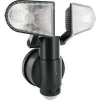
LED220 011 - Lighting Schwaiger - Free user manual and instructions
Find the device manual for free LED220 011 Schwaiger in PDF.


| Brand | Schwaiger |
| Model | LED220 011 |
| Category | Outdoor Security Lighting |
| Product Type | LED Lamp with Motion Detector |
| Power Supply | 3 LR14 (C) 1.5V batteries (not included) |
| Brightness | 600 lumens |
| Detection Range | 0.3 to 9 meters (adjustable) |
| Detection Angle | 130° |
| Lighting Duration | 10 to 30 seconds (adjustable) |
| Brightness Threshold | Dusk to dark (adjustable) |
| Protection Class | IPX4 (waterproof) |
| Mounting Type | Wall-mounted only |
| Installation | Drilling 2 holes Ø5 mm |
| Installation Time | Approximately 45 minutes |
| Batteries | 3 alkaline LR14 (C size) batteries |
| Battery Status Indicator | Red for low batteries |
| Operating Temperature | -20°C to 40°C (estimate) |
| LED Lifespan | Up to 30 years (3h/day) |
| Cleaning | Soft cloth, non-abrasive cleaner |
| Safety | Do not touch LEDs, do not look directly |
| Warranty | According to purchase conditions |
Frequently Asked Questions - LED220 011 Schwaiger
User questions about LED220 011 Schwaiger
0 question about this device. Answer the ones you know or ask your own.
Ask a new question about this device
Download the instructions for your Lighting in PDF format for free! Find your manual LED220 011 - Schwaiger and take your electronic device back in hand. On this page are published all the documents necessary for the use of your device. LED220 011 by Schwaiger.
USER MANUAL LED220 011 Schwaiger
natural_image
Black and white photo of a dual-light security camera with two lenses (no text or symbols visible)LED220 011
natural_image
Mechanical device diagram showing rotational motion with arrows indicating direction (no text or symbols)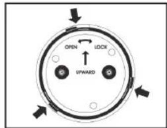
natural_image
Diagram of a symmetrical mechanical or anatomical structure with two flanged ends and directional arrows, labeled '1' (no text or symbols within the diagram itself)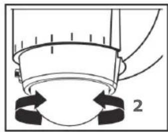
natural_image
Diagram of a mechanical component with arrows indicating motion or force direction (no text or symbols)LEDs can be damaged by electro static discharge (ESD) shock. Before installation, discharge yourself by touching a grounded bare metal surface to remove this hazard. To avoid damage, do not remove the clear lens over the LED module.
IMPORTANT SAFETY INSTRUCTIONS
- Do NOT touch LEDs.
- Do NOT remove the protective clear LED lens.
- Do NOT look directly at lighted LEDs for any length of time.
- Electrical requirements: 4.5 V DC, 3x 1.5 V LR14 (C)
- Fixture can only be wall mounted. NOT suitable for ground mount or eave mount installations.
Select the installation location carefully. Do not install in areas having pedestrian or motorized traffic, pools or bodies of water, or trees/bushes that move in the wind. All of these may trigger the motion sensor led lamp and may be disruptive to the intended operation of the light.
TO BEGIN:
WARNING:
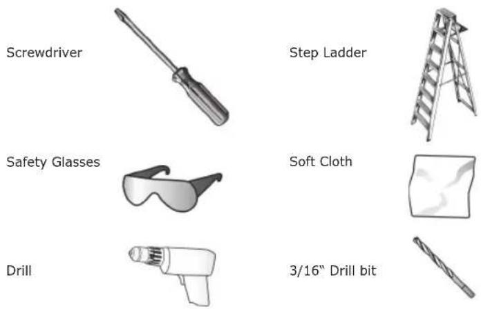
Review important safety instructions before installation. Check to make sure you have the following:
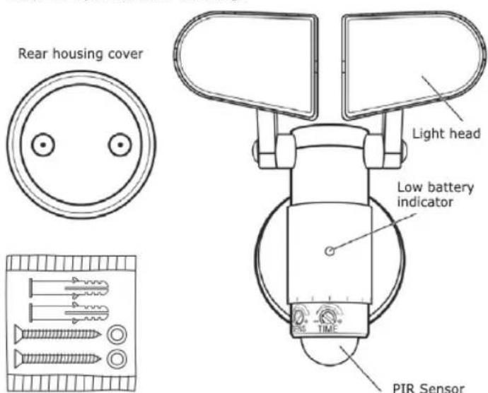
Hardware Kit (Actual hardware may differ from illustration.)
ITEMS REQUIRED
Installation Time: 45 Minutes.
FIXTURE INSTALLATION
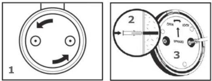
Remove the rear housing cover by turning counter-clockwise until it comes loose (Fig. 1)
For mounting to concrete or masonry, install the anchors, by drilling two 3/16-in. pilot holes into the mounting surface. Insert the anchors into the holes and tap them into place so they are fl ush with the surface (Fig. 2). Place the rear housing cover, with the writing facing away from the wall, over the mounting location and secure the rear housing cover to the mounting surface with wood screws (Fig. 3).
USER MANUAL LED220 011
The motion sensor can be rotated to position in the direction of an area to be covered. If the 2 tick marks are aligned, the motion sensor is focused straight ahead. The motion sensor can be rotated approximately 45 degrees right or left of center (Fig. 2). The motion sensor has a maximum detection field of 130^ at a distance of 30 ft.
4 5
6
Remove the screw on the battery compartment cover (Fig. 4). With your fi ngertip, pull up on the battery compartment catch and pull out-ward to remove the battery compartment cover (Fig. 5).
Insert 3 new alkaline C cell batteries (not included) into the battery compartment and orient them with the '+' and markings on the back of the battery compartment (Fig. 6). Re-attach the battery compartment cover by aligning the legs on the lower edge of the battery compartment cover onto the fi xture body and close the cover until the catch at the top engages. Replace the screw. Do not mix old and new batteries. Cold weather may have a negative impact on battery life.
The control knobs for adjusting the operation of the led lamp (TIME, SENS and LUX) are located on the back side of the motion sensor. To gain access to these controls, rotate the sensor clock-wise until they are in view (Fig. 3).
3
456
7
Attach the led lamp to the rear housing cover by positioning the led lamp over the rear housing cover at an angle. Engage the led lamp into the grooves of the rear housing cover and secure by twisting clockwise until the led lamp is seated vertically (Fig. 7).
OPERATING INSTRUCTIONS
The individual light heads can be adjusted side to side and up/down independently to aim the light heads in the direction desired (Fig. 1).
The TIME control knob can be adjusted to control the length of time the light stays ON when triggered by the PIR sensor (Fig. 4). In the far left position (-), the duration time is approximately 10 seconds. In the far right position (+) the duration time is approximately 30 seconds.
The SENS control knob can be adjusted to control the range of the PIR sensor (Fig. 5). The far left position (-) sets the PIR sensor range to approximately 1 foot. The far right (+) sets the PIR range to approximately 30 feet.
The LUX control knob can be adjusted for the surrounding level of darkness needed to activate the PIR (Fig. 6). This is quite variable. The far left position (-) sets for minimum level of darkness. The far right position (+) sets for a maximum level of darkness (or near full darkness).
1 2

USER MANUAL LED220 011
BATTERY REPLACEMENT
When the red LED low battery indicator on the front of the led lamp is lit the batteries are low and need to be replaced. Alkaline batteries can last up to 300 days if the led lamp is activated for 10 seconds at 4 times per night.
natural_image
Diagram of a mechanical device with directional arrows indicating motion or force (no text or symbols)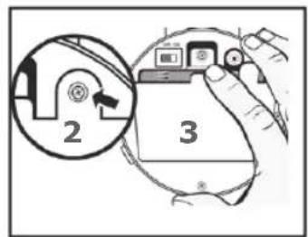
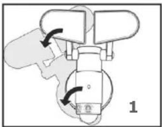
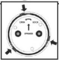
Remove the led lamp from the rear housing cover by gripping the fi xture and turning counter clockwise until the catches disengage from the rear housing cover (Fig. 1)
Remove the screw on the battery compartment cover (Fig. 2). With your fi ngertip, pull up on the battery compartment catch and pull out-ward to remove the battery compartment cover (Fig. 3). Remove the old batteries and discard.
natural_image
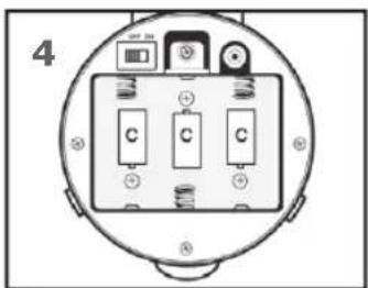
Mechanical diagram showing a valve mechanism with directional arrows (no text or labels)Insert 3 new alkaline C cell batteries (not included) into the battery compartment according to the "+" and markings near the battery drawings (Fig. 4). Re-attach the battery compartment cover by aligning the legs on the lower edge of the battery compartment cover onto the fi xture body and close the cover until the catch at the top engages. Do not mix old and new batteries. Cold weather may have a negative impact on battery life.
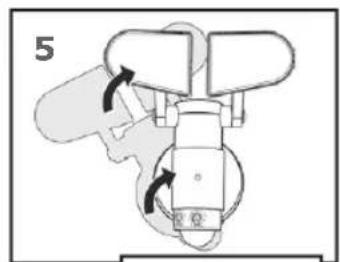
Re-attach the led lamp to the rear housing cover by positioning the led lamp over the rear housing cover at an angle; engaging the led lamp into the grooves of the rear housing cover until the led lamp is seated vertically (Fig. 5).
CARE AND MAINTENANCE
IMPORTANT:
Periodically clean the fi xture and diffuser using a mild, non-abrasive cleaner and soft cloth. When cleaning the fi xture, make sure the power is turned off. Do not spray cleaner directly onto any part of the fi xture or LEDs.
IMPORTANT:
This fi xture uses LEDs (light emitting diodes) to provide light. LEDs do not burn out like traditional light bulbs and will last for 30 years or more (based on 3 hours of usage per day).
Technical Data
| Brightness of the lamp: 600 Lumen (lm) | |
| Coverage range: approx. 0,3 - 9 m | |
| Coverage angle: | approx. 130° |
| Duration of glowing in „TIMER" mode: | approx. 10 - 30 seconds |
| Condition for the „SENS" function: | Twilight - Darkness |
| Class of protection: watertight according to IPX4 (suitable for the outdoors) | |
| Voltage supply: 3 x 1.5 V LR14 (C) | (4.5 V), not included |
TROUBLESHOOTING GUIDE
Extreme hot or cold weather could affect the performance of the built-in sensors that detect body heat. Certain winter clothing can shield a person's body heat from the sensor during extreme cold weather. During extreme hot weather, the sensor may not be able to distinguish the difference between normal body temperatures and the surrounding high temperatures. The sensor will begin working normally once weather conditions return to normal.
| Problem Cause Solution | ||
| Fixture does not light. | 1.ON/OFF switch Is not set correctly.2. Batteries are defective.3. Batteries are Installed wrong.4. Battery compartment cover Is loose. | 1. Slide ON/OFF switch to ON position.2. Replace the batteries.3. Install the batteries correctly.4. Check battery compartment cover and/or screw. |
| Light f ickers on and off. | Photo sensor Is picking up extraneous light. | Remove batteries to reset photosensor settings. |
| Fixture stays on all night. | Heat source / refl ective body in detection area. | Remove heat source/refl ective body from detection zone or move fi xture. |
| Motion sensor ac-tivates at random or for no reason. | 1. Momentary heat source or reflective body.2. Minor sensor problem. | 1. Turn sensor detection field away from source.2. Remove batteries to reset sensor. |
| Motion sensor does not activate at all. | 1. Batteries are depleted.2. ON/OFF switch Is set to OFF. | 1. Check or replace batteries.2. Slide switch to ON position. |
| Detection range varies from day to day. | Changes in meteorological conditions. | Adjust the position of the sensor. |
Disposal

Do not dispose of batteries or electric and electronic devices in the normal household waste. The consumer is legally obliged to return electrical and electronic devices and batteries that are at the end of their useful life to the point of sale or public collection points that have been set up for this purpose.
Legislation in the country of use governs individual details regarding disposal. The symbol on the product, the user guide or the packaging indicates this legal requirement.
Guarantee information
The guarantee period begins with the purchase of the product. Please confirm this with your proof of purchase (receipt, invoice, delivery receipt etc.). Please keep these documents in a safe place. Our guarantee is based on our guarantee conditions in force at the time of purchase. In the case of a necessary repair, take or send in the unit to your specialist dealer.

F MODE D'EMPLOI LED220 011
ATTENTION:
natural_image
Mechanical device diagram showing rotational components with arrows indicating motion (no text or symbols)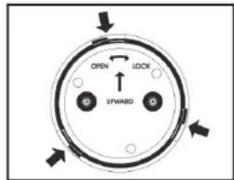
natural_image
Diagram of a mechanical or anatomical assembly with two symmetrical components and directional arrows, labeled '1' (no text or symbols on the diagram itself)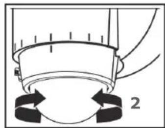
natural_image
Diagram of a mechanical component with arrows indicating motion or force direction (no text or symbols)natural_image
Diagram of a mechanical device with directional arrows indicating motion or force (no text or symbols)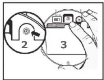
natural_image
Mechanical diagram showing a rotating device with directional arrows indicating motion (no text or symbols)natural_image
Mechanical device diagram showing rotational components with arrows indicating motion (no text or symbols)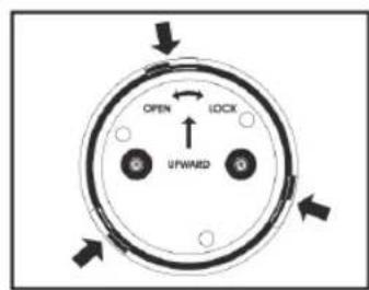
natural_image
Diagram of a mechanical or anatomical assembly with two symmetrical components and directional arrows, labeled '1' (no text or symbols on the diagram itself)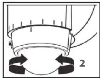
natural_image
Diagram of a mechanical component with arrows indicating motion or force direction (no text or symbols)natural_image
Diagram of a mechanical device with directional arrows indicating motion or force (no text or symbols)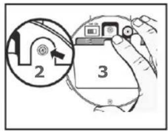
natural_image
Mechanical assembly diagram showing a valve mechanism with directional arrows (no text or labels)natural_image
Mechanical device diagram showing rotational and linear motion arrows (no text or symbols)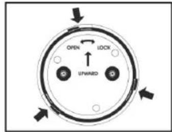
natural_image
Diagram of a mechanical or anatomical assembly with two symmetrical components and directional arrows indicating motion (no text or symbols)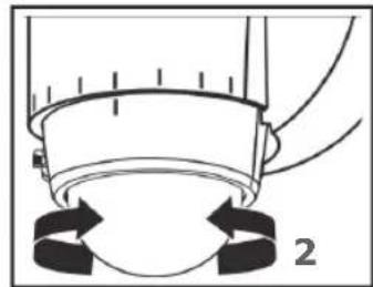
natural_image
Diagram of a mechanical component with arrows indicating motion or force direction (no text or symbols)natural_image
Diagram of a mechanical device with directional arrows indicating motion or force (no text or symbols)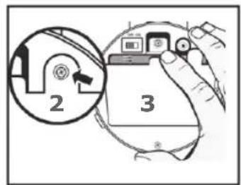
natural_image
Mechanical diagram showing a valve mechanism with directional arrows (no text or labels)MANUFACTURER INFORMATION
Dear Customer,
should you require technical advice and your retailer could not help please contact our technical support.
Business hours:
Monday to Friday: 08:00 - 17:00
Schwaiger GmbH
Würzburger Straße 17
90579 Langenzenn
Hotline: +49 (0) 9101 702-299
www.schwaiger.de
info@schwaiger.de
Brand : Schwaiger
Model : LED220 011
Category : Lighting