VT35 - Intercom Pentatech - Free user manual and instructions
Find the device manual for free VT35 Pentatech in PDF.


User questions about VT35 Pentatech
0 question about this device. Answer the ones you know or ask your own.
Ask a new question about this device
Download the instructions for your Intercom in PDF format for free! Find your manual VT35 - Pentatech and take your electronic device back in hand. On this page are published all the documents necessary for the use of your device. VT35 by Pentatech.
USER MANUAL VT35 Pentatech
natural_image
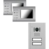
Two grayscale images of a mobile phone wall-mounted device, one with a camera and display screen, the other with a control panel (no visible text or symbols)1. Einleitung
natural_image
Metallic component with mounting holes and a central square cutout, labeled 14, 15, 16, 17 (no text or symbols on the part itself)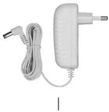
natural_image
White handheld electronic device with coiled cable and power plug (no visible text or symbols)B
natural_image
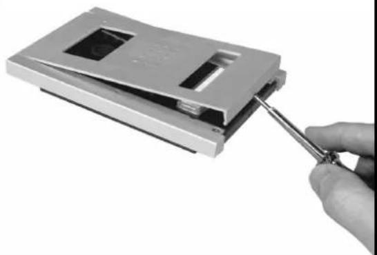
Hand inserting a screwdriver into a device component (no visible text or symbols)C
text_image
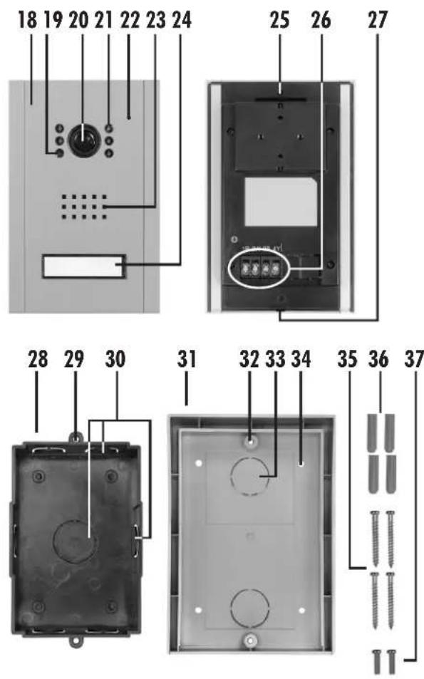
18 19 20 21 22 23 24 25 26 27 28 29 30 31 32 33 34 35 36 37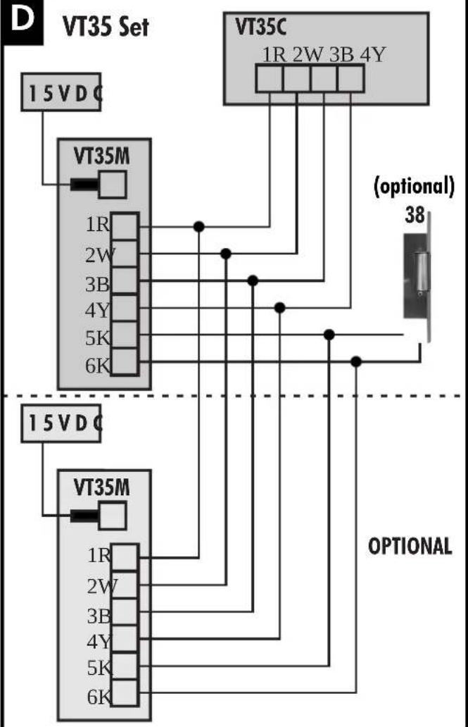
flowchart
graph TD
    A["15 VDC"] --> B["VT35M"]
    B --> C["1R"]
    B --> D["2W"]
    B --> E["3B"]
    B --> F["4Y"]
    B --> G["5K"]
    B --> H["6K"]
    I["VT35C"] --> J["1R 2W 3B 4Y"]
    J --> K["(optional) 38"]
    L["15 VDC"] --> M["VT35M"]
    M --> N["1R"]
    M --> O["2W"]
    M --> P["3B"]
    M --> Q["4Y"]
    M --> R["5K"]
    M --> S["6K"]
    T["OPTIONAL"] --> U
InnenstationVT35M
De video-intercomsysteem is nu operationeel.
13. Bediening
Read through these operating instructions completely and carefully. The operating instructions are an integral part of the product and contain important information about operation and handling. Always observe all the safety instructions. If you have any questions or are unsure about using the equipment, ask a specialist or obtain information online at www.pentatech.de. Keep these instructions in asafeplace and passthemon to third parties if necessary.
2. Properuse
This video door intercom VT35 consists of an outdoor station VT35C and an indoor station VT35M which are connected using a four-core connection cable. Themaximumcablelengthis70m.
The power supply is provided using the supplied mains adapter which is connected to the indoor station.
Achimeisheardattheindoorstationwhenthedoorbellbuttonispressed.
The camera installed in the outdoor station is activated automatically and the camera image is displayed on the monitor of the indoor station.
The camera image is displayed in colour. The infrared illumination integrated in the outdoor station is activated during darkness to illuminate the face of the person standing in front of the camera. The camera image is displayed in black and white. The image quality in bad light conditions will be improved by additional lighting.
By touching a button on the indoor station a two-way conversation is enabled.
The camera and microphone can be activated for observation by touching a buttonontheindoorstation.
Anadditionalindoorstation(notsupplied)canbeconnected.
Anelectric 12VDCdoorrelease(notsupplied)canbeconnectedtotheindoor station if desired. This can be activated at the indoor station by pressing a button.
The outdoor station is suitable for surface or flush mounting, and must be protected from directrain.
The indoor station and themains adapter are only approved for indoor use.
Thesystemisonlyforprivateuseandnotforcommercialuse.
Any other use or modification of the equipment is not authorised and presents significant risks of accident. No liability will be accepted for consequential damages or for damages caused by improper use or incorrect operation.
This equipment is not suitable for use by persons (including children) with limited physical, sensory, or mental abilities or with lacking experience or lacking knowledge unless they are supervised by a person responsible for their safety or obtain instructions on how to use the equipment. Children must besupervised to make sure they don't play with the equipment.
3. Packagecontents
Check the package contents are complete and that the equipment is undamagedimmediatelyafterunpacking.
1x indoorstation(incl.wallbracket)
1x outdoorstation
1x surfacemounthousing
1x flushmounthousing
1x mainsadapterwithapprox.1,8mcable
6x mountingscrews
6x wallplugs
2x machinescrews
1x operatinginstructions
4. Technicaldata
OutdoorstationVT35C
| Operatingvoltage: fromtheindoorstation(12V DC) --- | |
| Powerconsumption: | max.300mA |
| Cameraimagesensor: | 1/4"CMOScolour |
| Cameraimageresolution: | 648x488pixels |
| Cameralensangleofview: | approx.100°horizontal,approx.68°vertical |
| Illumination: | 5 infrared LEDs (for illumination of the close rangeduringdarkness) |
| Daylightsensor: | activatesLEDsindarkness |
| Dimensions: | outdoorstationwithouthousing: approx.99x152x28mm flushmounthousing approx.87x139x42mm approx.110x156x31mm |
| Operatingtemperature: | -10°Cto + 45°C |
| Protectionclass: | IP44 |
| connectioncable: | required: 4x0,8mm ^2 ,max.70mtoindoorstation |
| normalmountingheight: | 150cm(camera) |
| min.mountingheight: | 135cm(camera) |
IndoorstationVT35M
| Operatingvoltage: 15V | DC === |
| Currentconsumption: | max.1A |
| chime: | max.76dB(A) ± 3dB(A)(atdistanceof1m) |
| Monitor | 3,5"TFTLCDcolour (visiblediagonal85mm) |
| Monitorresolution: | 320x240pixels |
| Voltage for door release: | 12 V === DC (max. 1 A) (The door release mustmeetthesespecifications) |
| Dimensions: | approx.134x90x35mm |
| Operatingtemperature: | ±0°Cto + 35°C |
| Application: | indooruseonly,IP20 |
Mainsadapter
Powersupply: 100-240V AC,50-60Hz \~
Poweroutput: 15V DC,1 A ===
Application: indooruseonly
5. Equipment
IndoorstationVT35M(seeFig.A)
1 monitor
2 doorreleasebutton
3 monitorOFFbutton
4 monitorONbutton
5 talkbutton
6 microphone
7 terminals
8 connectionformainsadapter
9 cablechannel
10 keyholeslot
11 loudspeaker
12 plug
13 fixingscrews
14 wallbracket
15 fixinghole
16 lug
17 mainsadapter
IndoorstationVT35C(seeFig.C)
18 coverplate
19 daylightsensor
20 cameralens
21 infraredLEDs
22 microphone
23 loudspeaker
24 doorbellbuttonwithnameplate
25 fixinghole
26 terminals
27 slot
28 flushmounthousing
29 fixingholeforoutdoorstation
30 cablehole
31 surfacemounthousing
32 fixingholeforoutdoorstation
33 cablehole
34 fixinghole
35 mountingscrew
36 plug
37 machinescrew
Connectiondiagram(seeFig.D)
38 electricdoorrelease(option)
6. Safetyinstructions
The following instructions are provided for your safety and satisfaction during operation of the machine. Note that non-observance of these safety instructions results in significant risk of accident.
Danger! If this point is not heeded life and health is endangered.
- Do not leave small children unsupervised with the product, packaging material or small parts. Otherwise there is a risk of fatal injury due to choking.
- Perform the connection and installation while the mains power is disconnected! Otherwise there is a risk of fatal injury due to electric shock.
- Do not damage any gas, electricity, water or telecommunication lines during drilling and fixing work. Otherwise there are dangers of personal and fatal injury.
- Treat the supply lines carefully. Lay these so that they cannot be damaged and do not present any tripping hazard. Fix the cables sufficiently. Do not pull the cables over sharp edges and do not crush or crimp them elsewhere. Otherwise there are dangers of personal and fatal injury.
- Do not place the equipment near fire, heat or long lasting high temperature effects of more than +45 °C. Otherwise there is a risk of fatalinjuryduetofire.
- Do not connect any external voltage to the connection terminals. Otherwise there are dangers of personal and fatal injury and fire.
- Use a mains adapter near to the indoor station and keep it easily accessible.
- Plug the mains adapter for the mains power connection into the mains socket completely. Do not touch it with wet hands. Otherwise there is a riskoffatalinjuryduetoelectricshock.
- Only operate the indoor station and the mains adapter in dry areas. Do not expose them to dripping or splash water. Only clean the equipment with a dry and, if necessary slightly moist, cloth. Do not submerge the equipment in water. Otherwise there is a risk of fatal injury due to electricshockandfire.
- Do not connect any damaged device (e.g. transport damage) and disconnect the power supply immediately in the case of damage. Unplug the mains adapter from the mains socket. Arrange for the damage to be repaired immediately by a specialist. Otherwise there is a riskoffatalinjuryduetoelectricshockandfire.
- Onlyoperatethesystemwith15.0VDCfromthesuppliedpowersupply. Beforeconnectingthe power supplytothemains, ensure thatthemains currentcomplieswith230VAC,50Hzandisfittedwithafuseaccording to regulations. Otherwise there is a risk of fatal injury due to electric shockandfire.
- Protect the equipment and the cables against strong magnetic or electricalfieldsandagainststrongmechanicalloadsandvibrations.
- Only have repairs carried out by authorised and trained qualified personnel. Otherwise there is a risk of damage due to improper use and invalidationofthewarranty.
7. Planningtheinstallation
Observethefollowingpoints:
Outdoorstation
- Protecttheoutdoorstationagainstdirectrainfall.
- Mounttheoutdoorstationatsuchaheightthat visitors can comfortably reachthedoorbellbutton andthat theface ofthepersonringingthebell is in the field of view of the camera (normal mounting height: 150cm min.mountingheight:135cm).
- The outdoor station is usually installed at the side of the entrance door. Ensure that the face of the visitor standing in front of the door can be seen on the screen. The horizontal detection angle of the camera is approx. 100^ .
- Arrange the outdoor station so that no direct light falls on the lens opening. Avoid strong backlighting behind the visitor: in this case, the person appears darker on the image. Check the camera image before mounting. Puttheunitintooperationandholdtheoutdoorstationinthe desired place for this. If necessary, change the position until you have foundtheoptimumimagedetail.Rememberthatthepositionofthesun changes.
• Suitable, possible cablerouting must be available.
Indoorstation
- Mount the indoor station on the wall at a central place inside the residence, e.g. in the hall. Ensure that the chime can be heard everywhere insidetheresidence.
- If the chime is not sufficiently audible, an additional indoor station can beconnected(seechapter"optionalaccessories").
- Arrange the indoor station at face height so that you can observe the monitor. Take account of the height of everybody living in the residence including children when determining themounting height.
- Ensure that there is a mains power socket for the mains power supply withintherangeofthemainsadaptercable.
- Pay attention to the length of the necessary connection cable to the outdoorstation. The maximum length is 70 m. A suitable existing cable can be used if needed (wire cross section min. 0,8 mm ^2 , max. length 70 m). For short cabling length, less than 20 m, a cable core min. 0,5 mm ^2 canbeused). Avoid laying the connection cabled directly next to current-carrying lines as this adversely affects the image and sound quality.
8. Checkingthefunction
- Provisionally lay a suitable 4-core connection cable from the intended installation location of the outdoor station to the intended installation location of the indoor station.
- Connect the connection cable to the indoor station (see chapter "Connection").
- If applicable, connect an optional door release (not included in the scope of delivery) with a two-core cable (not included) to the outdoor station(seechapter"Connection").
- Connect the low-voltage connector of the mains adapter [17] to the connection.
• Plugthemainsadapterintoamainspowersocket.
- Checkthefunction(seechapter"Operation").
- Checktheimagedetail.
• Optimisetheplacementoftheequipment.
• Unplugthemainsadapterfromthemainssocket.
- Disconnectallotherconnections.
• Nowproceedwiththenextchapter.
9. Installation of cable and housings
Notesaboutcabling:
- Laycables such that they are protected from weather,forexampleinthe wallorincabletrunking.
- Make sure you leave approx. 50 cm additional cable to facilitate connectionattheindoorandtheoutdoorstation.
- Stripthe insulationattheendof eachcablecoretoa lengthofapprox.8 mmforconnectiontothescrewterminals.
- When connecting a door release follow the instructions of the manufacturer.
The outdoor station can be flush or surface mounted. Use the appropriate housing:
Installingthesurfacemount housingfortheoutdoorstation
• Pressouttherequiredcablehole[33]inthehousing[31].
- Hold the housing at the chosen location and mark the necessary fixing holes[32]andcableholeonthewall.
• Drillthesuitableholesforthecableandforthefixingscrews.
• Fixthehousingusingthesuppliedscrews[35]andwallplugs[36].
- Pull the connection cable through the hole in the wall and through the cableholeinthehousing.
Installing the flushmount housing for the outdoor station
• Pressouttherequiredcablehole[30]inthehousing[28].
- Make a hole at the chosen location in the wall suitable for the flush mounthousing, approx. 87x139x42mm (Wx H x D).
- Hold the housing in the hole and mark the necessary cable hole on the wall.
- Drillasuitableholeforthecable.
- Fixthehousingcarefullyintheholesothatherimofthehousingisflush with the wall. Fill out the gap between the wall and the housing using silicon.
- Pull the connection cable through the hole in the wall and through the cableholeinthehousing.
Installationofthewall bracketfortheindoorstation
- Hold the bracket [14] on the chosen location (the location lugs [16] must point upwards) and mark the required fixing holes [15] and, if required, acablehole(aboveorbelowthebracket)onthewall.
- Drillsuitablefixingholesandifnecessaryasuitablecablehole.
• Fixthebracketusingthesuppliedscrews[13]andwallplugs[12]. - If necessary pull the connection cable and the2-coredoor release cable throughtheholeinthewall.
10. Personalisingthenameplate
- Removethecoverplate[18]fromtheoutdoorstation,leveringitusinga flatbladedscrewdriverintheslot[27]intheloweredge(seeFig.B).
• Pulltheplasticcoverfromthenameplate[24].
• Writethenameonthepaperinsert. - Replacetheplasticcover.
11. Connection
Warning!
Ensure correct connection of the individual cores. A wrong connection will cause incorrect function.
- ConnectalldevicesaccordingtoFig.D.12.
12. Installation and commissioning
1. Indoorstation
- Lay the connection cable and the mains adapter [17] cable in the cable channel[9]andhangtheindoorstationsecurelyonthelugs[16].
2. Doorrelease(optional)
- Install a 12 V DC door release according to the manufacturers instructions.
3. Installation of the outdoor station
- Remove the cover plate [18] from the outdoor station, if not already removed, levering it using a flat bladed screwdriver in the slot [27] in the lower edge (see Fig. B).
- Secure the outdoor station using the two machine screws [37] to the fixed housing.
- Replace the cover plate on to the outdoor station, by hanging it over the top edge and then pressing downwards until all four corners are clicked into place.
4. Commissioning
• Plugthemainsadapter[17]intoamainspowersocket.
• Removetheprotectivefilmfromthemonitor[1].
• Removetheprotectivefilmfromthecameralens[20].
The video oore ntry system is now ready for operation.
13. Operation
A visitor presses the doorbell button [24] of the outdoor station. A chime soundsatthe indoor station. Thecameraimage appears onthemonitor and soundsneartheoutdoorstationcanbeheard.
If the visitor pressesthedoorbellbuttonagain, the chimesoundsagain.
• Pressthetalkbutton[5]inordertospeaktothevisor.
- To endtheconversation to turn off the monitor press the monitorOFF button [3], otherwisethe unit will turn off automaticallyafterapprox. 2 minutes.
If you do not react to the visitor pressing the doorbell button, the monitor imageisextinguishedafterapprox.30seconds.
Activationofthemonitorfromtheindoorstation
- PressthemonitorONbutton[4]inordertoseethecameraimage onthe monitor. The camera image appears on the monitor and sounds near the outdoor station can be heard.
• ToturnoffthemonitorpressthemonitorOFFbutton[3].
If nobuttons are pressed the display will turn off automatically after approx. 30 seconds.
Doorrelease(optional)
If a door release is connected, you can release the door or gate by pressing the door release button [2]. The door / gate is released during the time that the button is pressed.
The door release can be activated at any time.
14. Maintenance + cleaning
• Theunitismaintenance-free
• Regularlycheckthetechnicalsafetyandfunctioning
- Before you clean the device, pull the mains adapter out of the mains socket. Use a drycloth forcleaningthe surfaces. Forstubborn dirt, clean the surfaces with a soft, fluff-free, slightly moist cloth without cleaning additives
• Cleanthespeakerandmicrophonecarefullywithadrybrush
15. OptionalAccessories
- VT35M,Additionalindoorstation,partNo.27063
16. Disposal

Packaging material, used batteries or electrical products must not be disposed of as household waste. Use your recycling system. Details are available from your local authority.
- Troubleshooting
| Fault | Cause | Remedy |
| No image is displayed | The power supply is interrupted | Check the power supply |
| No image is displayed | The connection between the outdoor station and the indoor station has been interrupted | Check the connection and polarity |
| The cable is too long or its cross section is too small | Use a suitable cable (wire cross section at least 0,8 mm2, max. length 70 m) | |
| A whistling sound can be heard | It is produced by acoustic feedback | Place the indoor and the outdoor stations further apart from each other |
| No sound | The power supply is interrupted | Check the power supply |
| The connection between the outdoor station and the indoor station has been interrupted | Check the connection and polarity | |
| Dark monitor image during twilight / darkness | The outdoor station needs additional light in order to be able to display a good image | Arrange additional lighting |
| The image is also too dark during daylight | Your viewing angle to the monitor [1] is unfavourable | Change the mounting height of the indoor station |
| The monitor image displays a bright background, however the visitor is displayed dark | There is too much backlighting in the background | Install additional lighting or change the installation location of the outdoor station |