
I-PAC - Heat pump Calorex - Free user manual and instructions
Find the device manual for free I-PAC Calorex in PDF.


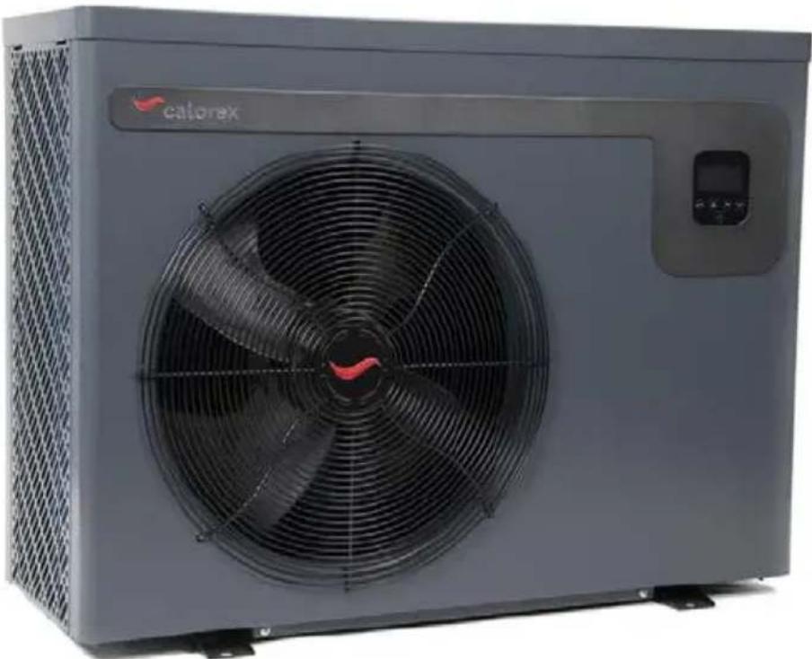
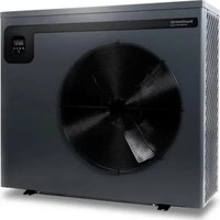
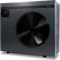
| Product type | Air-source heat pump for swimming pool |
| Brand | Calorex |
| Model | I-PAC / I-PAC+ (IPT ranges) |
| Dimensions (L x W x H) - model IPT16 ALX | 954 x 359 x 748 mm |
| Net weight - model IPT16 ALX | 68 kg |
| Power supply | 230 V single-phase / 400 V three-phase depending on model |
| Refrigerant | R32, charge from 0.6 to 2.7 kg depending on model |
| Operating range - air temperature | -5 °C to +43 °C (I-PAC) / -10 °C to +43 °C (I-PAC+) |
| Water heating adjustment range | 18 °C to 40 °C |
| Water cooling adjustment range | 12 °C to 30 °C |
| Heating capacity (Air 27°C/Water 27°C) | 9.5 to 36 kW depending on model |
| Average COP at 50% speed | 6.3 to 10.6 depending on model and conditions |
| Operating modes | Boost (20-100% capacity) and Whisper (20-80%, 3 dB(A) quieter) |
| Compressor | DC inverter with no bearing |
| Heat exchanger | Titanium cross-flow high efficiency |
| Defrost | Automatic reverse cycle and forced via control |
| Connectivity | Integrated Wi-Fi, mobile app for control |
| Sound level at 10 m (model IPT16 ALX) | 24.3 to 36.1 dB(A) depending on mode |
| Water connection | Female 1½" or 50 mm |
| Maintenance and cleaning | Disconnect power, wait 3 min, clean with mild detergent or clean water |
| Safety | High/low pressure protection, water shortage stop, anti-freeze protection, screen lock |
| Spare parts and repairability | Intervention reserved for qualified F-Gas technicians |
| Warranty | Subject to water chemistry conditions (pH 7.2-7.8, etc.) and proper installation |
| General information | Manual available in French, English, German, etc. |
Frequently Asked Questions - I-PAC Calorex
User questions about I-PAC Calorex
0 question about this device. Answer the ones you know or ask your own.
Ask a new question about this device
Download the instructions for your Heat pump in PDF format for free! Find your manual I-PAC - Calorex and take your electronic device back in hand. On this page are published all the documents necessary for the use of your device. I-PAC by Calorex.
USER MANUAL I-PAC Calorex
I-PAC / I-PAC+ inverter heat pumps
IPT 8, 12, 16, 22, 28
Owner Installation Manual 1005494 Issue 6

HEALTH AND SAFETY WARNING
This product contains electrical and rotational equipment. ONLY competent trained people should work on this device, and must be isolated electrically before removing access panels.
This appliance can be used by children from 8 years and above and persons with reduced physical, sensory or mental capabilities or lack of experience and knowledge if they have been given supervision or instruction concerning use of the appliance in a safe way and understand the hazards involved. Children should not play with the appliance. Cleaning and user maintenance shall not be made by children without supervision.
CONTENTS
HEALTH AND SAFETY WARNING 2
1.0 INTRODUCTION 4
1.1 FOREWORD 4
1.2 WARNINGS 4
2.0 ABOUT YOUR HEAT PUMP .8
2.1 TRANSPORTATION 8
2.2 ACCESSORIES 8
2.3 OPTIONAL ACCESSORIES.. 9
2.4 FEATURES 10
2.5 OPERATING CONDITIONS AND RANGE ...10
2.6 OPERATING MODES 10
3.0 INSTALLATION 11
3.1 POSITIONING AND AIRFLOW 11
3.2 REFRIGERANT TYPE AND INSTALLED LOCATION 14
3.3 POOL WATER CIRCUIT 15
3.4 PLUMBING 16
3.5 INITIAL CHECKS 16
3.6 ELECTROLYTIC CORROSION IN SWIMMING POOLS 17
3.7 ELECTRIC WIRING AND SUPPLY 17
3.8 CONNECTING THE HEAT PUMP TO THE POWER SUPPLY 18
3.9 POOL PUMP SYNCHRONISATION TERMINALS P1 AND P2 19
3.10 INSTALLING THE OPTIONAL REMOTE CONTROLLER 20
4.0 USING YOUR HEAT PUMP 22
4.1 THE KEY PAD 22
4.2 OPERATING INSTRUCTIONS 23
4.3 USING THE APP 24
4.4 USING THE OPTIONAL REMOTE CONTROLLER 30
4.5 THE KEY PAD 30
4.6 OPERATING INSTRUCTIONS 31
5.0 TESTING 32
5.1 HEAT PUMP MALFUNCTION 32
5.2 PROTECTION CODES 33
5.3 FAULT CODES 34
6.0 MAINTENANCE 35
7.0 TROUBLE SHOOTING COMMON FAULTS.....35
8.0 DATASHEETS 36
9.0 DIMENSIONS 39
9.1 DIMENSIONS 40
10.0 WINTERISATION PROCEDURE 41
10.1 START UP PROCEDURE AFTER WINTERISATION 41
11.0 WARRANTY CONDITIONS 42
12.0 DECLARATION OF CONFORMITY 43
1.0 INTRODUCTION
1.1 FOREWORD
Thank you for choosing this product, which is designed for quiet and energy efficient operation. It is the ideal way to heat your pool in an environmentally friendly way.
This guide provides information needed to install and operate the product effectively. Please ensure you read this manual and use the correct installation and operating procedures.
This manual is intended for installers and users. Read the entire manual before using the heat pump. Awareness of the correct operating procedure for the machine and any safety devices is important, to avoid damage or injury.
The appliance can be used by children aged from 8 years and above and persons with reduced, physical, sensory or mental capabilities or lack of experience and knowledge if they have been given supervision or instruction concerning use of the appliance in a safe way and understand the hazards involved. Children shall not play with the appliance. Cleaning and user maintenance shall not be made by children without supervision.
1.2 WARNINGS
Important safety information is contained in this manual and marked on the heat pump.
Please read and follow all safety advice.
The refrigerant used in this heat pump is R32. This refrigerant is environmentally friendly, but safety instructions must be strictly adhered to.

The WARNING sign denotes a hazard. It calls attention to a procedure or practice, which if not adhered to could result in injury. Warning signs and procedures must be complied with.
If a refrigerant leak is suspected stop using the heat pump and contact Dantherm Group UK service.
service.department@dantherm.com
Take the following precautions in order to avoid any danger:
REFRIGERANT SAFETY:
This heat pump contains R32 refrigerant. Work on the refrigeration system, repair and disposal must be carried out by appropriately qualified and registered engineers.
Repair, service and disposal must be carried out in the EU by F-Gas registered engineers.
Completely de-gas the refrigerant before any brazing is performed. Brazing can only be carried out by technicians trained to EU 517/2014.
Risk assessments must be carried out before maintenance or repairs are started.
Appropriate safety measures and risk assessments must be taken before work commences.
Do not attempt to work on the equipment by yourself.
Consult the qualified engineer undertaking the work to establish all requirements before work commences.
ACTIONS TO AVOID (OPERATION AND HANDLING):
Be especially careful when handling the heat pump, not to cause any damage that may result in leakage of the cooling circuit.
Do not use means to accelerate the defrosting process or to clean, other than those recommended by the manufacturer.
Do not pierce or burn.
IN CASE OF FIRE:
Toxic fumes may occur in the event of fire. You must leave the room as quickly as possible in the event of fire.
LOCATION REQUIREMENTS:
The heat pump contains R32 refrigerant so the following location requirements must be fulfilled:
The heat pump must be kept away from sources of fire or naked flames.
The heat pump must be installed, operated and stored where the floor area is larger than the minimum requirement., see section 3.2.
The heat pump shall be stored in a room without continuously operating ignition sources (for example: open flames, an operating gas appliance or an operating electric heater).
Keep the ventilation openings clear of obstruction during operation.
Do not use or store combustible gas or liquids near the heat pump.
Check if there are any local regulations, which you must comply to, when installing or storing the heat pump.
Be aware that refrigerants may not contain an odour.
Installation must be carried out by competent people, in accordance with this manual.
INSTALLATION:
Read the instructions before installation, use and maintenance.
If R32 gas leaks during the installation process, stop the installation immediately and call the service centre.
If a repair is required, please contact the nearest after-sales service centre.
To avoid over heating or over cooling of pool water check and set the temperature on the control panel.
The heating performance can be improved by insulating the flow and return pipework.
It is recommended that a cover is used on the swimming pool to reduce heat losses.
AIRFLOW:
The heat pump must have access to adequate airflow. See section 3.1.
Do not place obstructions that will block air flow near the inlet or outlet.
ELECTRICAL SAFETY:
Mains power isolator should be out of reach of children.
After a power cut, when the power supply is restored, the heat pump may start up without warning.
Electric storms can damage electronic equipment. Ideally the heat pump should be switched off at the mains.
HEAT PUMP MALFUNCTION:
WARNING: Isolate heat pump electrically and wait 3 minutes before removing panels or entering heat pump.
Refer to the user check list in section 5.2 and the error codes listed in section 5.3 before initiating a service call.
Do not attempt to interfere with any internal control settings as these have been factory calibrated and sealed.
Any sign of abnormal operation such as water dripping should be reported immediately to the installer. If in doubt or if advice is required contact the Service support team on telephone +44(0)1621 856611 (option 4).
MAINTENANCE:
Isolate the power supply of the heat pump and wait 3 minutes before cleaning examination or repair.
Please clean this machine with household detergents or clean water. NEVER use petroleum spirit, thinners or any similar fuel.
Check bolts, cables and connections regularly.
DISPOSAL:
Repair, service and disposal of redundant heat pumps must be completed by authorised technicians. It is illegal to allow refrigerant gases to escape to air.
Do not attempt to work on the equipment by yourself. Improper operation may cause danger.
| R32 Gas | Do not use means to accelerate the defrosting process or to clean, other than those recommended by the manufacturer. | The heat pump must be kept away from sources of fire or naked flames. | |
| The appliance shall be stored in a room without continuously operating ignition sources (for example: open flames, an operating gas appliance or an operating electric heater. | The heat pump must be installed in well ventilated area. Closed areas are not permitted. | ||
| Do not piece or burn. | Repair and disposal must be carried out by F-Gas registered engineers. | ||
| Be aware that refrigerants may not contain an odour. | |||
| Appliance shall be installed, operated and stored in a room with a floor area larger than Xm2, where X is the “minimum area” shown in section 3.2 and section 8.0. | Completely de-gas the refrigerant before any brazing is performed. Brazing can only be carried out by technicians trained to EU 517/2014. |
2.0 ABOUT YOUR HEAT PUMP
2.1 TRANSPORTATION
Always keep the heat pump upright.
Do not lift the heat pump by the water inlet or outlet connections.
(If this is done the titanium heat exchanger inside the heat pump could be damaged).
2.2 ACCESSORIES
These accessories are provided with the heat pump.

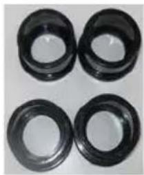
Water union connectors
$$ \begin{array}{l} 2 \times 1 \frac {1}{2}, \ 2 \times 5 0 m m \ \end{array} $$
Rubber Feet
KIT of 4
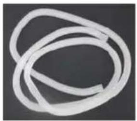
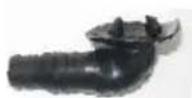
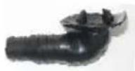
Drainage kit
2.3 OPTIONAL ACCESSORIES
The following items are additional accessories available for purchase.
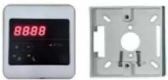
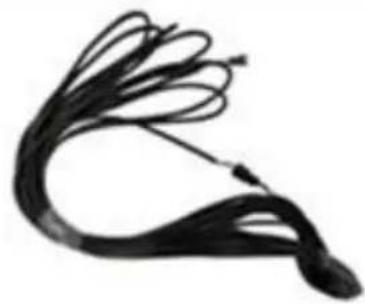
Remote controller kit for indoor installation.
(10m extension cable).
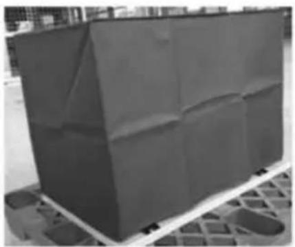
Winter cover.
2.4 FEATURES
- Stepless DC inverter compressor
- EEV Technology (Electronic Equalisation Valve)
- Quick reverse cycle defrosting with 4-way valve
- High-efficiency twisted titanium heat exchanger
High pressure and low pressure protection - Soft start and wide voltage application
- Stable inverter control system
2.5 OPERATING CONDITIONS AND RANGE
Air temperature operating range:
I-PAC (IPT X models): -5-43°C
I-PAC+ (IPT Y models): -10-43°C
Water temperature setting range:
Heating: 18^ - 40^
Cooling: 12^ - 30^
2.6 OPERATING MODES
The heat pump has two modes: Boost mode and Whisper mode.
| Mode Modes | Characteristics | |
| 41 | Boost mode | Heating capacity: 20% to 100% capacity Intelligent optimization Fastest heating |
| 41 | Whisper mode | Heating capacity: 20% to 80% capacity Sound level: 3dB(A) lower than Boost mode |
3.0 INSTALLATION
Installation must only be attempted by competent personnel.
3.1 POSITIONING AND AIRFLOW

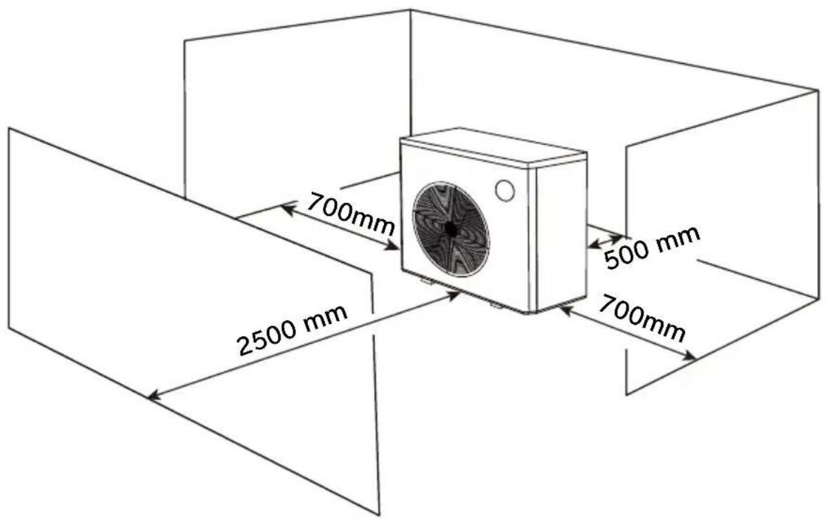
The heat pump must be positioned in a well
ventilated area. Minimum distances between the heat pump and any obstructions are shown below.
- The heat pump must be fixed by M10 bolts to a concrete base or mounting brackets. These must be solid and fixed securely. Brackets must be corrosion proof.
- Do not block inlet or outlet grilles.
Airflow - general principles
The heat pump absorbs energy from the air drawn through it. To function effectively the heat pump must have access to the fresh air it needs.
Air must not recirculate. The air leaving the heat pump must not be sucked back into the inlet.
Air must not be restricted. The air volume must not be reduced.
- The minimum required distances shown below must be provided to minimise the risk of air recirculation or restriction and reduction in performance. Further examples are shown on the following page.
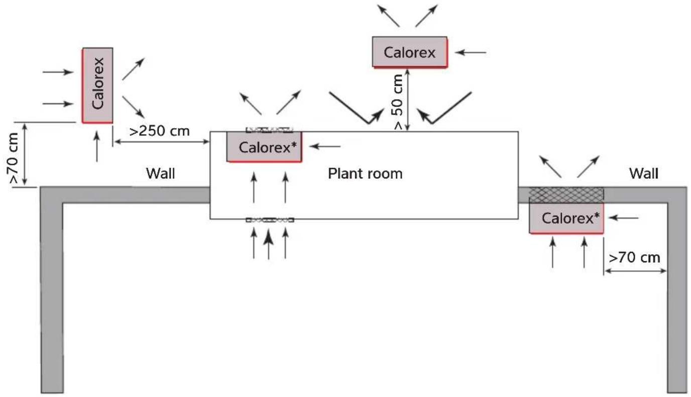
Possible positions of a Calorex heat pump
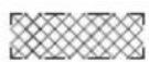
Suitable opening
Calorex
The red lines represent the air inlet area
- Controls are obscured by the wall. Connect to optional remote control panel or Wi-Fi before installing the heat pump in position.
Required free areas to provide air flow to and from heat pumps when installed in an enclosed area or where required to pass air through a wall etc. Ensure the heat pump is sealed against the wall so the outlet air cannot recirculate. Ensure the hole through the wall is sealed to avoid the outlet air entering cavities and is smooth so the outlet air is not restricted.
Free area is the available area through which air can pass through a grille or louvres.
| Minimum free areas m2 | |
| Model Discharge area | |
| IPT 8 0.169 | |
| IPT 12 0.169 | |
| IPT 16ALX 0.169 | |
| IPT 16ALY 0.229 | |
| IPT 22 0.301 | |
| IPT 28 0.301 | |
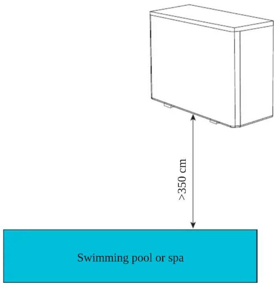
To comply with safety regulations regarding electrical installations in wet areas the heat pump must be installed at least 350cm away from the edge of the pool or spa.
3.2 REFRIGERANT TYPE AND INSTALLED LOCATION
This heat pump contains R32, which is an environmentally friendly refrigerant with a GWP (Global Warming Potential) of 675. R32 has the safety in use classification of A2L, being low toxicity and lower flammability. In practical terms it is very difficult to ignite an A2L refrigerant, but this classification requires a risk assessment to be undertaken for the possibility of refrigerant being released by accident into an area connected to the heat pump, considering the application, location of components, and the installed refrigerant charge. This installation guidance can form the framework for such a risk assessment for the installation.
All flammable refrigerants will not ignite if the concentration level in a room stays below their lower flammability limit (LFL). European standard EN378 defines requirements to remain far below the lower flammable limit in case of accidental leakage. By choosing the location as dictated by EN378-1:2016 the probability of forming a flammable atmosphere can be eliminated. Please refer to the minimum area for each product and the interpretation below regarding locations of heat pump and swimming pool. This information is provided as a guide only and does not supersede the regulations or health and safety requirements.
| Model IPT | 8ALX IPT1 | 2ALX IPT16 | ALX IPT22AL | X IPT12ALY | IPT16ALY | IPT22A/BLY | IPT28ALY | ||
| Refrigerant charge | R32 kg | 0.6 | 0.9 | 1.1 2 | 0.9 | 1.2 | 2 2.7 | ||
| Minimum area | m2 3.1 | 6.9 | 10.3 | 34.0 | 6.9 | 12.3 | 34.0 | 62.0 | |
| Notes *Assumed worst case for access category: a - general access and location class: I - mechanical equipment in occupied space; both as defined in line with EN378-1 2016 section 5.1 table 4 and section 5.3 *Minimum Area is calculated in line with section C.2 on EN378-1 2016 (calculation C.2) | |||||||||
INTERPRETATION
Please refer to the installation situations below for how to apply the minimum area stated above.
Pool outside and heat pump outside:
Automatically meets the minimum area requirement because outside space is unlimited.
Pool outside and heat pump inside a plant room:
Automatically meets the minimum area requirement because the room must open to the outside for heat pump airflow and the outside space is unlimited.
Pool inside and heat pump outside:
The pool hall must exceed the minimum area requirement shown above.
Pool inside and heat pump inside a plant room, isolated from the pool hall:
The pool hall must exceed the minimum area requirement shown above.
Pool inside and heat pump inside a plant room, ventilated to the pool hall:
The pool hall and plant room combined must exceed the minimum area requirement shown above.
3.3 POOL WATER CIRCUIT
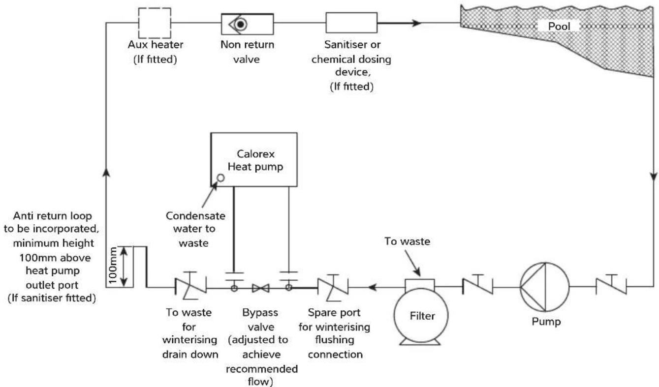
| KEY | |
| Isolation valve | N |
| Breakable coupling | + |
| Three way valve | N |
3.4 PLUMBING
IMPORTANT
Before installing the heat pump ensure the blanking disks are removed from the pool water in/out connections. These should drop out when the adaptors are unscrewed.
- Ensure that bypass is installed and set to achieve the recommended flow rates stated in the data sheet.
- Ensure that the condensate drain kit supplied is fixed and is drained to a drain or soak-away. (It is best to do this first before the heat pump is fixed to pipework or the ground).
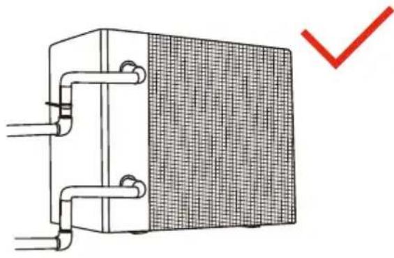
- Inlet and outlet pipework must be supported to avoid excessive strain on the connections.
- Water quality must be maintained. See warranty conditions.
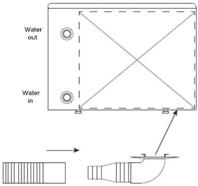
Hose. Condensate adaptor.
Fit in hole in base of unit. Approximate position shown.
Note: Fittings shown at larger scale for clarity.
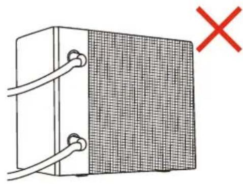
3.5 INITIAL CHECKS
Start the filtration pump before the heat pump is turned on, and turn off the heat pump before the filtration pump. It is recommended to turn off the heat pump prior to backwashing.
Before starting the heat pump, please check for any leakage of water; and check/set the required temperature on the controller, and then turn on.
In order to protect the components, the heat pump incorporates time delays. When starting heating/cooling the fan will run for one minute before the compressor starts. When the heat pump stops heating/cooling, or is turned off by the user, the fan will continue to run for one minute.
After starting up, check for any error codes or abnormal noise from the heat pump.
3.6 ELECTROLYTIC CORROSION IN SWIMMING POOLS
Electrolytic corrosion will occur when dissimilar metals that are in contact with each other create a potential difference between themselves. Sometimes separated by a conductive substance known as an electrolyte, the dissimilar metals will create a small voltage (potential difference) that allows the ions of one material to pass to the other.
Just like a battery, ions will pass from the most positive material to the more negative material.
Anything more than 0.3 volts can cause the most positive material to degrade.
A swimming pool with its associated equipment can create this effect. The pool water being an ideal electrolyte and components of the filtration circuit, heating system, steps, lights etc providing the dissimilar metals needed to complete the circuit.
Whilst these small voltages are rarely a safety threat, they can create premature failure through corrosion. Not dissimilar to corrosion through oxidation, electrolytic corrosion can cause complete failure of a metallic material in a very short period of time.
In order to prevent this type of corrosion all metallic components in contact with swimming pool water should be bonded together using 10mm^2 bonding cable. This includes non-electrical items such as metal filters, pump strainer boxes, heat exchangers, steps and handrails. It is highly recommended that bonding be retrofitted to existing pools, which may not be protected by this system.
3.7 ELECTRIC WIRING AND SUPPLY
All electrical work to be carried out in accordance with I.E.E. regulations, latest issue, or local codes of practice as applicable.
The machine should be installed in accordance with EMC2004/108/EC.
Always isolate the main power supply before removing machine covers.
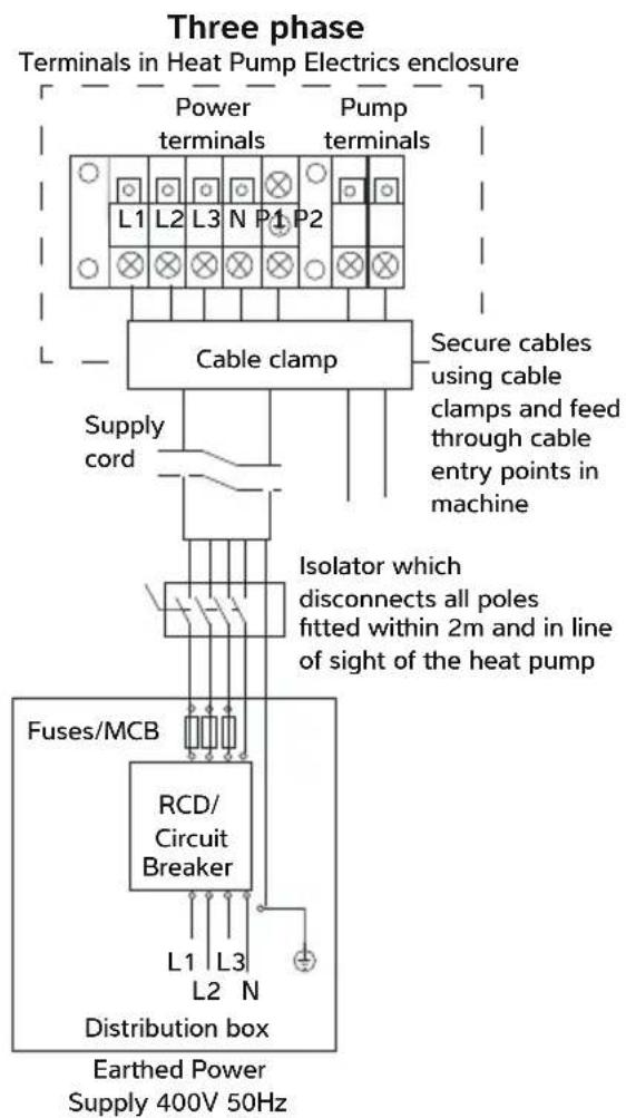
The machine power supply must incorporate the following. Fuses or motor type circuit breakers (aM Fuse / MCB type C) to specified rating (see datasheet). When using a fuse, H.R.C. fuses are recommended. An isolator which disconnects all poles must be must fitted within 2m and in line of sight of the heat pump. The isolator must have a minimum of 3mm air gap when turned off.
All units must be correctly earthed/grounded and its own separate type RCD earth leakage trip installed which protects the machine only. See data sheet for the correct type.
The following limits of operation must not be exceeded. Failure to provide the necessary voltages will invalidate the warranty. This voltage must be available at the heat pump whilst running. The voltage must not drop below the above figures when starting the compressor.
Minimum Maximum
Voltage
Single phase machines 207V 253V
Three-phase machines 360V 440V
Cycle frequency (50Hz) 47.5Hz 52.5Hz
3.8 CONNECTING THE HEAT PUMP TO THE POWER SUPPLY
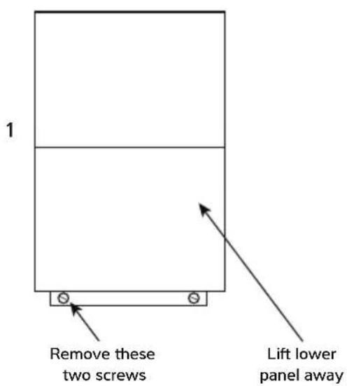
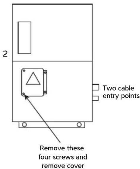
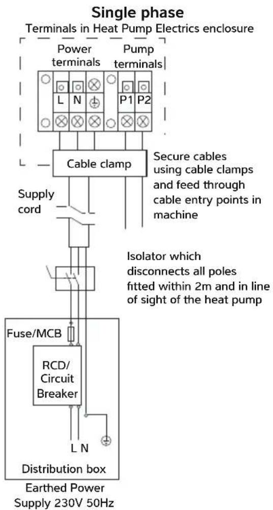
3.9 POOL PUMP SYNCHRONISATION TERMINALS P1 AND P2
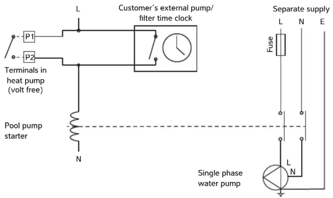
For installations where the pool filter pump runs continuously, these terminals do not need to be used.
For installations where a timeclock controls the pool filter pump, and the same pump provides water flow to the heat pump, the heat pump can override "pump off" periods to ensure the pool is heated/cooled. To activate this setting please speak to your installer.
When installed in parallel with the timeclock, the pool filter pump will run when:
a) a block period of "pump on" has been set on the time clock for filtration purposes.
b) the heat pump runs the pool filter pump for temperature sampling and if the pool subsequently requires heating/cooling.
This feature operates by over-riding the timeclock for 3 minutes to circulate the pool water through the heat pump to sample the water temperature. The default sampling time interval is 1 hour. If the
measured temperature is more than 1^ from the set temperature, the point heat pump will continue to run the filter pump and heat/cool the pool. If the measured temperature is within 1^ of the set temperature, the filter pump will turned off until the next sampling period, or the next timeclock "pump on" period.
When the pool pump is already running, and the heat pump is not heating/cooling, the heat pump will sample the water temperature once per hour and will start heating/cooling if needed. The heat pump will ignore a demand to heat/cool the pool until the sampling timer (default 1 hour) has elapsed*.
This feature will reduce the pool filter pump run time to minimise pump energy usage.
*If the pool filter pump is later changed to run continuously, it is recommended to de-activate this setting so the heat pump will respond to a heating/ cooling demand without waiting for the sampling time interval to elapse. To deactivate this setting please speak to your installer.
310 INSTALLING THE OPTIONAL REMOTE CONTROLLER
This optional accessory replaces the integral controller and can be installed up to 10m away.
Take the lid off the I-PAC to gain access to the existing controller. Remove the front cover. Disconnect the plug from the socket on the back of the controller as shown.
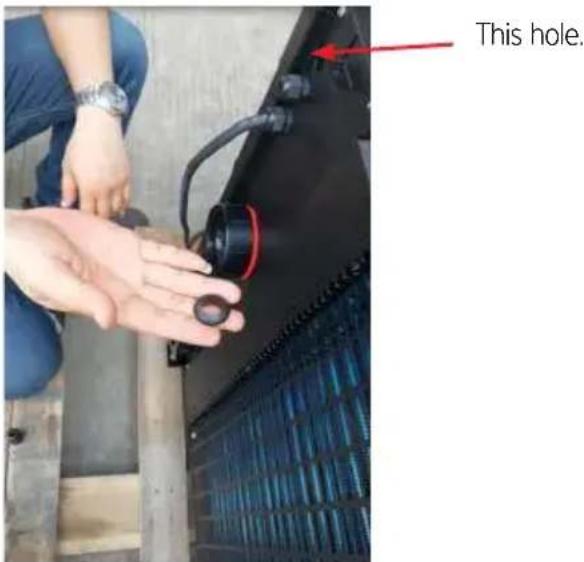
Remove the bulkhead connector from the position shown and replace it with a rubber grommet.
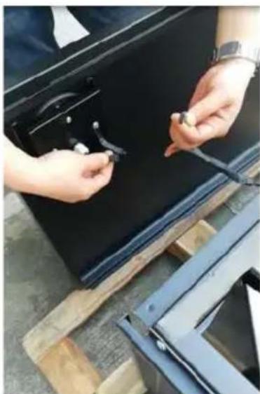
Feed the 10m cable through the grommet.
Route the cable inside the I-PAC securing it where necessary.
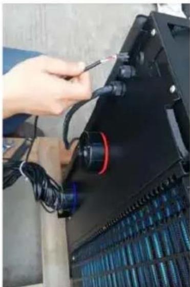
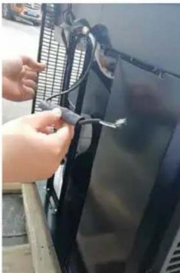
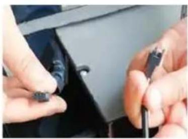
Connect the lead. Connect the lead.
Remove the two screws from the back of the Remote Controller.
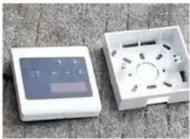
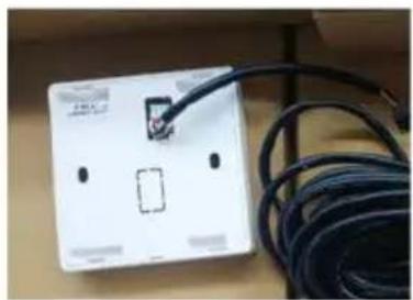
Remove the appropriate knock out and fit the back of the box to the wall.
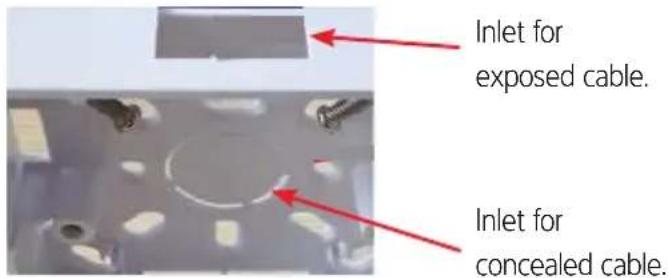
If the cable is concealed, fit the grommet in the hole to protect the cable from rubbing.
Secure the cable from the controller in the I-PAC
Refit the front cover and the top cover.
To check that the installation is correct, set the temperature on the remote controller to slightly higher than the pool water. The I-PAC should run to heat the pool, immediately if the pump synchronisation is not in use, or at the next sampling period if pump synchronisation is in use.
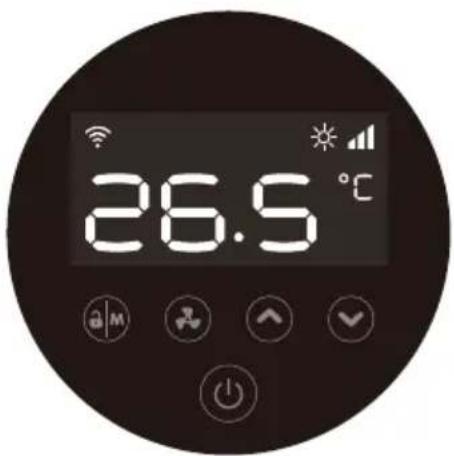
| Symbol Designation | Function | |
| On/Off | 1. Power On/Off 2. Wi-Fi Setting | |
| aM | Lock/Unlock and Heat Mode | 1. Lock/Unlock Screen 2. Heating mode (18-40°C) 3. Cooling mode (12-30°C) 4. Auto mode (12-40°C) |
| Speed Mode | 1. Boost 2. Whisper | |
| Up/Down Temperature Setting | ||
The buttons will turn dark when the controller is locked.
4.2 OPERATING INSTRUCTIONS
IMPORTANT
Remember that at startup there is a 1 minute time delay before the heat pump starts
a. Screen lock
1) Press seconds to lock or unlock the screen. The buttons will turn dark when the controller is locked.
2) Automatic lock period: 30 seconds if no operation.
b. Power on
Press seconds to unlock screen.
Press power on the heat pump.
c. Temperature setting
Press and to display and adjust the set temperature.
d. Mode selection
- Heating/Cooling/Auto
Press to switch between heating, cooling, and automatic modes.
| Mode Symbol Water temperature setting range |
| Heating |
| 18-40°C |
| Cooling 12-30°C |
| Auto |
| 12-40°C |
e. Speed Mode selection
Press switch between Boost mode and Whisper mode.
Default mode: Boost.
Please choose Boost mode for initial heating.
f.Wi-Fi
When the screen is on, press 3 seconds, after flashes, enter Wi-Fi connection.
Connect Wi-Fi on mobile phone and input password, then control equipment by Wi-Fi. When APP connects Wi-Fi successfully light is on.
g. Defrosting
- Automatic defrosting: When the heat pump is defrosting, the lamp flashes; after defrosting the lamp stops flashing.
- Forced defrosting: When the heat pump is heating and the compressor has been running continuously for at least 10 minutes, press l and simultaneously for 5 seconds to start forced defrosting. The lamp flashes and defrost starts, when the lamp stops flashing defrosting stops.
The interval between forced defrosts must be more than 30 minutes.
4.3 USING THE APP
a. APP Download b. Account registration
- Register by mobile or E-mail.
Android please download from
iOS please download from
- Mobile or E-mail registration.
Obtain verification code
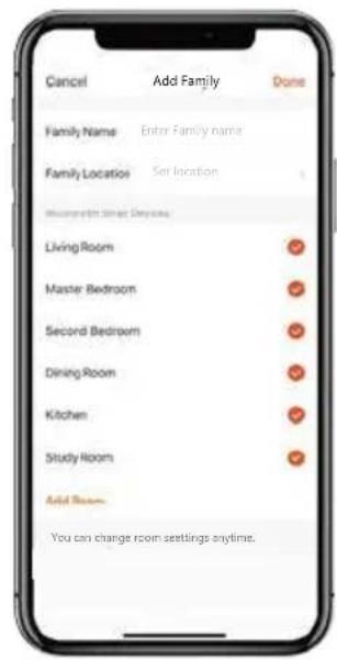
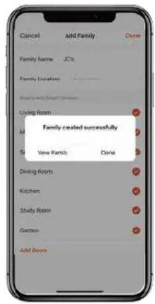
c. Create family
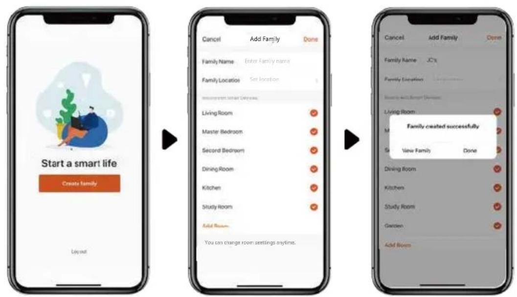
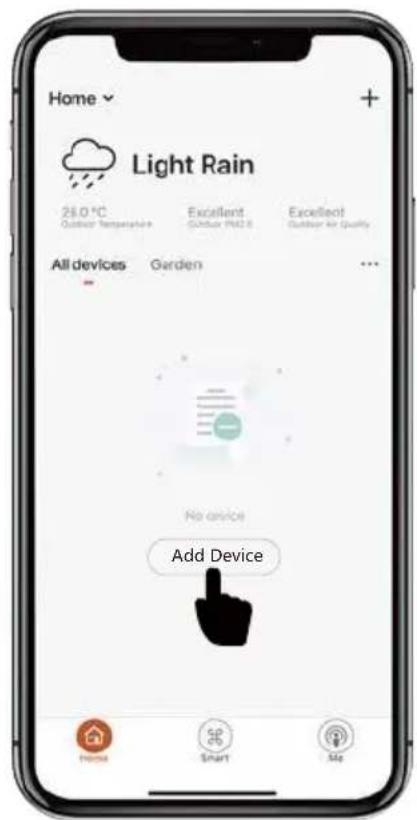
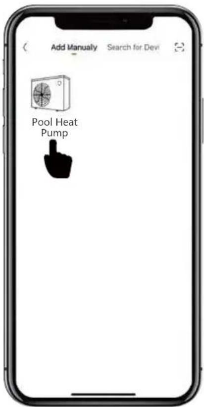
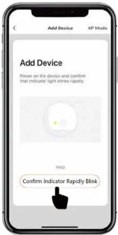
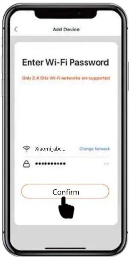
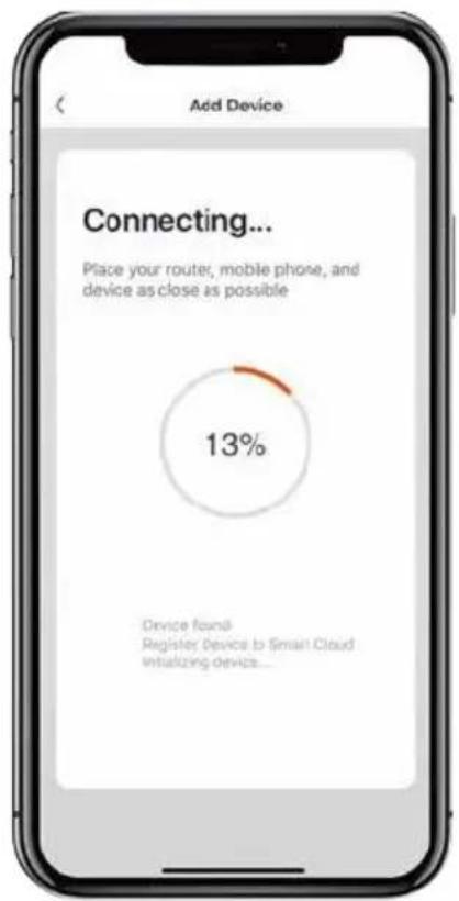
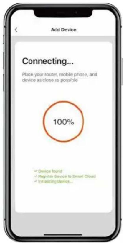
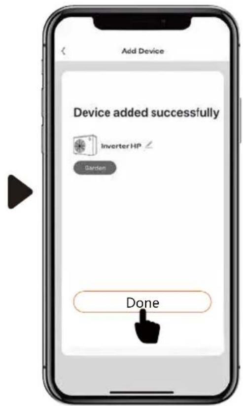
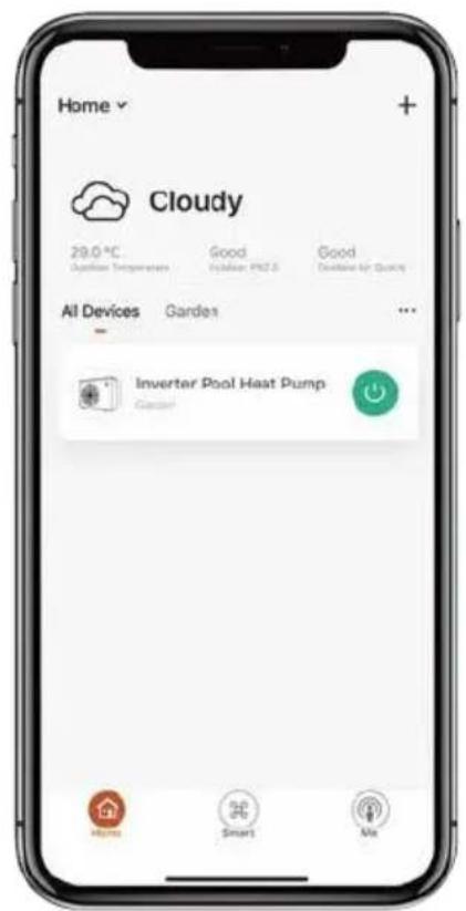
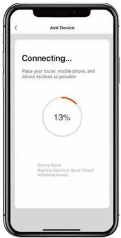
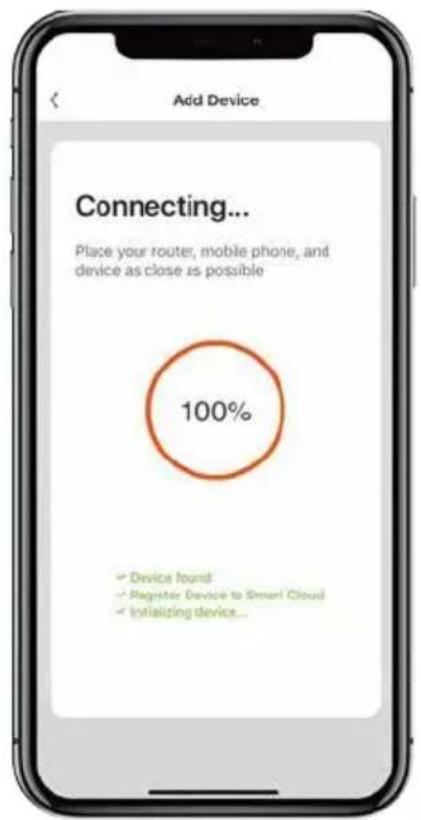
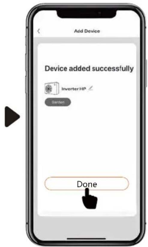
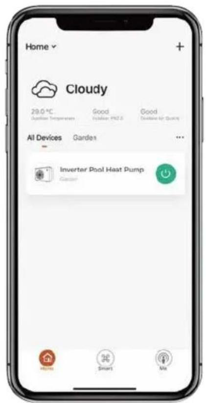
d. APP Pairing
Please make sure you are connected to the Wi-Fi.
- Press three seconds to unlock the screen.
- Press "O" for three seconds then release, after hearing the beep, enter the Wi-Fi code. During connection the " " flashes. When the APP connects to the Wi-Fi successfully the " light will come on.
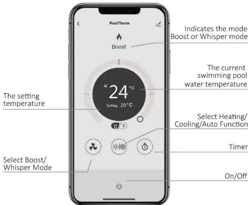
e. Operation
- For heat pump with Heating function only :
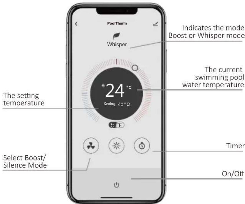
- For heat pump with Heating and Cooling function :
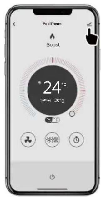
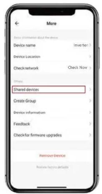
f. Share devices to your family members
After pairing, if your family members also want to control the device.
Please let your family members register the APP first, and then the administrator can operate as below:
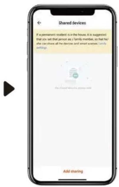

Notes:
- The weather forecast is just for reference.
App is subject to updating without notice.
4.4 USING THE OPTIONAL REMOTE CONTROLLER
4.5 THE KEY PAD
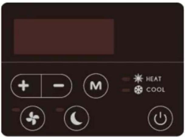
| Symbol Function | ||
| Power On/Off | ||
| Heating/Cooling/Auto mode | ||
| Press to start Boost mode | ||
| Press to start Whisper mode | ||
| + | - | Temperature setting and display. |
4.6 OPERATING INSTRUCTIONS
a. Power On & Power Off
Press to power on or power off the heat pump.
b. Temperature Setting
Press + - to display and adjust temperature.
c) Mode selection
- Heating/Cooling/Auto modes
Press to choose heating, cooling and automatic mode.
In heating mode the light is on.
In cooling mode the.
In automatic mode the and the light are on.
- Whisper and Boost modes
Press to start Boost mode, and light will turn on.
Press to start Whisper mode, and light will turn
on. (Default mode is Boost).
Please choose Boost mode for initial heating.
c. Defrosting
- Automatic defrosting
When machine is defrosting, the lamp flashes; after defrosting the lamp is illuminated.
- Forced defrosting
When the heat pump is heating and the compressor has been working continuously for at least 10 minutes, press l and - on the touchscreen controller simultaneously for 5 seconds to start forced defrosting. The lamp flashes and defrost starts, when the - lamp stops flashing defrosting stops.
The interval between forced defrosts must be more than 30 minutes.
5.0 TESTING
Inspect the heat pump before use
- Check that the fan, air inlets and outlets are not obstructed.
- It is prohibited to install refrigeration pipe or components in corrosive environment.
5.1 HEAT PUMP MALFUNCTION
WARNING: Isolate heat pump electrically, and wait 3 minutes before removing panels or entering heat pump.
- Refer to the user check list in section 5.2 and the error codes listed in section 5.3 before initiating a service call.
-
Do not attempt to interfere with any internal control settings as these have been factory calibrated and sealed.
-
Check that the electric wiring conforms to the electric wiring diagram and that the machine is earthed.
- Double check that the main power switch is off.
-
Check the temperature setting.
-
Any sign of abnormal operation such as water dripping should be reported immediately to the installer. If in doubt or if advice is required contact the Service support team on telephone +44(0)1621 856611 (option 4).
Fault Reason Solution
| Heat pump doesn’t run | No power Wait until the power is restored |
| Power is switched off Switch on the power | |
| Fuse has blown Check and change the fuse | |
| The breaker is off Check and turn on the breaker | |
| Evaporator blocked Remove the obstructions | |
| Fan running but with insufficient heating | Air outlet blocked Remove the obstructions |
| Compressor start delay Wait for the delay timer to time out | |
| Display normal, but no heating | Set temperature too low Set desired heating temperature |
| Start delay Wait for the delay timer to time out | |
| Inaccurate switch action | |
| The fuse blows frequently or leakage circuit breaker trips frequently | Stop the machine, and cut off the power supply immediately, then contact your dealer |
If above solutions don't work, please contact your installer with detailed information and your model number. Don't try to repair it yourself.
5.2 PROTECTION CODES
These codes indicate machine stopping due to external circumstances.
These are not faults with the heat pump.
| No Display Reason Solution | |||
| 1 E3 | No water flow through the heat pump. Check water circuit and pool pump. | ||
| 2 E4 | Three phase rotation protection. | Check phases connected correctly (Electrician required) | |
| 3 | E5 | Voltage of power supply to heat pump is out of range. | Check the power supply. |
| 4 | E6 | Low water flow indicated by more than 10°C difference in inlet and outlet temperature. | Check water flow and pool pump. |
| 5 | Eb | Ambient temperature is out of range, either lower than -5°C (-10°C Y version) or higher than 43°C. | If outside, wait for ambient conditions to improve (winterisation may be required). If installed in a sheltered place, check for air recirculation. |
| 5 | Ed | Frost protection. The heat pump runs in heating mode for a short time when in standby mode to prevent frost build up. This does not replace winterisation. | Heat pump will resume standby once process is completed. |
53 FAULT CODES
When e heat pump displays eese error codes
please contact your installer for advice
| No D | splay Description of fault code |
| 1 E1 High pressure alarm | |
| 2 E2 Low pressure alarm | |
| 4 E7 Water outlet temp out of range alarm | |
| 5 E8 High exhaust temp alarm | |
| 6 EA Evaporator overheat alarm (only in cooling mode) | |
| 7 P0 Controller communication failure | |
| 8 P1 Water inlet temp sensor failure | |
| 9 P2 Water outlet temp sensor failure | |
| 10 P3 Gas exhaust temp sensor failure | |
| 11 P4 Evaporator coil pipe temp sensor failure | |
| 12 P5 Gas return temp sensor failure | |
| 13 P6 Cooling coil pipe temp sensor failure | |
| 14 P7 Ambient temp sensor failure | |
| 15 P8 Cooling plate sensor failure | |
| 16 P9 Current sensor failure | |
| 17 PA Restart memory failure | |
| 18 F1 Compressor drive module failure | |
| 19 F2 PFC module failure | |
| 20 F3 Compressor start failure | |
| 21 F4 Compressor running failure | |
| 22 F5 Inverter board over current protection | |
| 23 F6 Inverter board overheat protection | |
| 24 F7 Current protection | |
| 25 F8 Cooling plate overheat protection | |
| 26 F9 Fan motor failure | |
| 27 Fb Power filter plate - no power protection | |
| 28 FA PFC module over current protection | |
6.0 MAINTENANCE
Isolate the power supply of the heat pump and wait 3 Minutes before cleaning, examination or repair.
Cover the heat pump body when not in use.
Please clean this machine with household detergents or clean water, NEVER use petroleum spirit, thinners or any similar fuel.
Check bolts, cables and connections regularly.
Repair, service and disposal of redundant heat pumps must be completed by authorised technicians. It is illegal to allow refrigerant gases to escape to air.
Do not attempt to work on the equipment by yourself. Improper operation may cause danger.
7.0 TROUBLE SHOOTING COMMON FAULTS

Requirements for service personnel
Any person who is involved with working on or breaking into a refrigerant circuit should hold a current valid certificate from an industry-accredited assessment authority, F-Gas registered.
Do not attempt to work on the equipment by yourself.
8.0 DATASHEETS
| MODEL UNITS IPT8 | ALX IPT | 12 ALX IPT16 ALX | IPT22 ALX | ||
| PERFORMANCE CONDITION: Air 27°C/Water 27°C/RH 80% | |||||
| Heating capacity kW 9.5 13.0 20.0 | 25.0 | ||||
| COP range 13.2-5.4 13.5-5.6 13.5 | 5.7 13.8 | 5.8 | |||
| Average COP at 50% Speed | 8.9 | 9.7 | 9.3 | 9.6 | |
| PERFORMANCE CONDITION: Air 15°C/Water 26°C/RH 70% | |||||
| Heating capacity kW 7.0 | 9.5 | 13.5 | 17.0 | ||
| COP range | 6.9-4.2 | 7.0-4.0 | 7.0-4.2 | 7.2-4.0 | |
| Average COP at 50% Speed | 6.3 | 6.1 | 6.3 | 6.4 | |
| PERFORMANCE CONDITION: Air 35°C/Water 28°C/RH 80% | |||||
| Cooling capacity (kW) | 3.9 | 5.2 | 7.4 | 9.4 | |
| TECHNICAL SPECIFICATIONS | |||||
| Operating air temperature | °C | -5°C to 43°C | |||
| Water heating setting range °C | 18°C to 40°C | ||||
| Water cooling setting range | °C | 12°C to 30°C | |||
| POWER SUPPLY | 230V Single Phase 50Hz | ||||
| Rated input power | kW | 0.3-1.79 | 0.40-2.38 | 0.57-3.21 | 0.69-4.25 |
| Rated input current | A | 1.38-7.58 | 1.82-10.8 | 2.60-14.61 | 3.16-19.32 |
| Maximum input current | A | 9.5 | 12.5 | 19.5 | 20 |
| Rated RCD type F | mA | 30 | 30 | 30 | 30 |
| Rated Fuse aM / MCB type C | A | 16 | 16 | 25 | 25 |
| Sound pressure level at 10m | dB(A) | 19.6-31.5 | 21.9-32.0 | 24.3-36.1 | 24.9-36.7 |
| Recommended water flow rate | m³/h | 3.0-5.0 | 4.0-6.0 7.0-10.0 | 10.0 | 10.0-12.0 |
| Pressure drop | m/kPa | 0.36/3.5 | 0.41/4.0 | 0.56/5.5 | 0.77/7.5 |
| Pool water connections | Inches | 1½" or 50mm Female | |||
| GENERAL DATA | |||||
| Net dimensions (w x d x h) | mm | 864 x 359 x 648 | 864 x 359 x 648 | 954 x 359 x 748 | 1084 x 429 x 948 |
| Packed dimensions (w x d x h) | mm | 950 x 375 x 675 | 950 x 375 x 675 | 1040 x 375 x 775 | 1130 x 445 x 985 |
| Net weight | kg | 47 | 49 | 68 | 90 |
| HERMETIC SYSTEM | |||||
| Refrigerant charge R32 | kg | 0.6 | 0.9 | 1.1 | 2.0 |
| Minimum area requirement | m2 | 3.1 | 6.9 | 10.3 | 34.0 |
NOTES: Heat pump performance parameters are subject to change without notice. Always refer to the nameplate.
Global warming potential (GWP) R32 - 675.
The data is subject to modification without prior warning.
| MODEL UNITS IPT 12 | ALY IPT | 16 ALY IPT22 ALY | ||
| PERFORMANCE CONDITION: Air 27°C/Water 27°C/RH 80% | ||||
| Heating capacity kW 15.0 21.0 27.5 | ||||
| COP range 15.0-6.6 14.8-6.4 15.0-6.5 | ||||
| Average COP at 50% Speed 10.6 10.3 | 10.3 | |||
| PERFORMANCE CONDITION: Air 15°C/Water 26°C/RH 70% | ||||
| Heating capacity kW 10.5 14.5 18.0 | ||||
| COP range 7.7-4.6 7.1-4.6 | 7.5-4.6 | |||
| Average COP at 50% Speed | 6.4 | 6.3 | 6.3 | |
| PERFORMANCE CONDITION: Air 35°C/Water 28°C/RH 80% | ||||
| Cooling capacity | kW | 6.7 | 9.5 | 11.9 |
| TECHNICAL SPECIFICATIONS | ||||
| Operating air temperature | °C | -10°C to 43°C | ||
| Water heating setting range | 18°C to 40°C | |||
| Water cooling setting range | 12°C to 30°C | |||
| POWER SUPPLY | 230V Single Phase 50Hz | |||
| Rated input power | kW | 0.27-2.28 | 0.41-3.15 | 0.48-3.91 |
| Rated input current | A | 1.17-9.91 | 1.78-13.69 | 2.08-17.00 |
| Maximum input current | A | 13.5 | 17 | 20 |
| Rated RCD type F | mA | 30 | 30 | 30 |
| Rated Fuse aM / MCB type C | A | 20 | 25 | 25 |
| Sound pressure level at 10m | dB(A) | 20.8-24.5 | 20.4-33.7 | 23.0-34.4 |
| Recommended water flow rate | m³/h | 5.0-7.0 | 8.0-10.0 | 10.0-12.0 |
| Pressure drop | m/kPa | 0.49/4.8 | 0.61/6.0 | 0.77/7.5 |
| Pool water connections | Inches | 1½" or 50mm Female | ||
| GENERAL DATA | ||||
| Net dimensions (w x d x h) | mm | 954x359x648 | 954x429x755 | 1084x429x948 |
| Packed dimensions (w x d x h) | mm | 1040x445x655 | 1040x445x655 | 1130x445x985 |
| Net weight | kg | 52 | 68 | 90 |
| HERMETIC SYSTEM | ||||
| Refrigerant charge R32 | kg | 0.9 | 1.2 | 2.0 |
| Minimum area requirement | m2 | 6.9 | 12.3 | 34.0 |
NOTES: Heat pump performance parameters are subject to change without notice. Always refer to the nameplate.
Global warming potential (GWP) R32 - 675.
The data is subject to modification without prior warning.
| MODEL UNITS IPT16 | BLY IPT | 22 BLY IPT28 BLY | ||
| PERFORMANCE CONDITION: Air 27°C/Water 27°C/RH 80% | ||||
| Heating capacity kW 21.0 27.5 36.0 | ||||
| COP range 14.8-6.4 15.0-6.8 14.8-6.0 | ||||
| Average COP at 50% Speed 10.3 10.3 10.2 | ||||
| PERFORMANCE CONDITION: Air 15°C/Water 26°C/RH 70% | ||||
| Heating capacity kW 14.5 18.0 23.9 | ||||
| COP range 7.1-4.6 7.5-4.6 | 7.5-4.6 | |||
| Average COP at 50% Speed | 6.3 | 6.3 | 6.3 | |
| PERFORMANCE CONDITION: Air 35°C/Water 28°C/RH 80% | ||||
| Cooling capacity | kW | 9.5 | 11.9 16.0 | |
| TECHNICAL SPECIFICATIONS | ||||
| Operating air temperature °C | -10°C to 43°C | |||
| Water heating setting range | 18°C to 40°C | |||
| Water cooling setting range | 12°C to 30°C | |||
| Power supply | 400V Three Phase 50Hz | |||
| Rated input power | kW | 0.41-3.15 | 0.48-3.91 | 0.64-5.20 |
| Rated input current | A | 0.59-4.56 | 0.69-5.66 | 0.92-7.53 |
| Maximum input current | A | 5.8 | 7 | 9.5 |
| Rated RCD type B | mA | 30 | 30 | 30 |
| Rated Fuse aM / MCB type C | A | 10 | 10 | 16 |
| Sound pressure level at 10m | dB(A) | 20.4-33.7 | 23.0-34.4 | 22.1-34.2 |
| Recommended water flow rate | m³/h | 8.0-10.0 | 10.0-12.0 | 12.0-18.0 |
| Pressure drop | m/kPa | 0.61/6.0 | 0.77/7.5 | 0.85/8.5 |
| Pool water connections Inches | 1½" or 50mm Female | |||
| GENERAL DATA | ||||
| Net dimensions (w x d x h) | mm | 954x429x755 | 1084x429x948 | 1154x539x948 |
| Packed dimensions (w x d x h) | mm | 1040x445x655 | 1130x445x985 | 1200x555x985 |
| Net weight | kg | 68 | 93 | 120 |
| HERMETIC SYSTEM | ||||
| Refrigerant charge R32 | kg 1.2 | 2.0 | 2.7 | |
| Minimum area requirement | m2 12.3 34.0 62.0 | |||
NOTES Heat pump performance parameters are subject to change without notice. Always refer to the nameplate. Global warming potential (GWP) R32 - 675. The data is subject to modification without prior warning.
9.0 DIMENSIONS
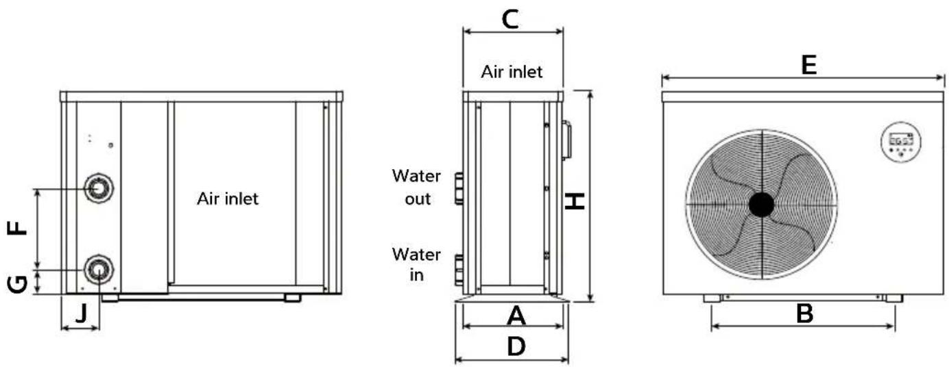
| ABC | DEFGH | J | |||||||
| IPT8 ALX 334 5 | 60 318 359 | 864 250 | 74 648 116 | ||||||
| IPT12 ALX 334 | 560 318 359 | 864 290 | 74 648 116 | ||||||
| IPT16 ALX 334 | 590 318 359 | 9 954 390 | 74 748 116 | ||||||
| IPT22 ALX 404 | 720 388 429 | 1084 640 | 74 948 107 |
| ABC | DEFGHJ | |||||||
| IPT12 ALY 334 | 590 318 35 | 9 954 340 | 74 648 107 | |||||
| IPT16 ALY 404 | 590 388 42 | 9 954 460 | 74 755 107 | |||||
| IPT16 BLY 404 | 590 388 42 | 9 954 460 | 74 755 107 | |||||
| IPT22 ALY 404 | 720 388 42 | 9 1084 62 | 0 74 948 107 | |||||
| IPT22 BLY 404 | 720 388 42 | 9 1084 62 | 0 74 948 107 | |||||
| IPT28 BLY 514 | 790 498 53 | 9 1154 65 | 0 74 948 128 |
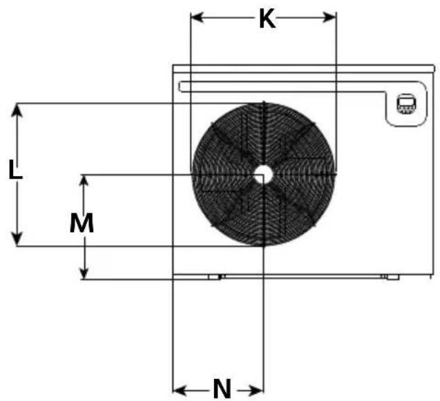
9.1 DIMENSIONS
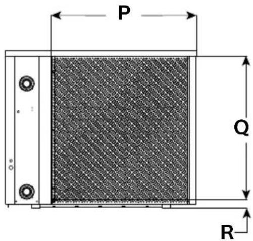
| K L M N | P Q R | ||||||
| IPT8 ALX | 478 465 | 285 288 533 | 565 50 | ||||
| IPT12 ALX | 478 465 | 285 288 630 | 565 50 | ||||
| IPT16 ALX | 478 465 | 349 315 675 | 666 50 | ||||
| IPT22 ALX | 645 630 | 462 405 799 | 861 50 |
| K L M N | P Q R | ||||||
| IPT12 ALY | 478 465 | 300 349 743 | 566 50 | ||||
| IPT16 ALY | 587 540 | 370 349 731 | 667 50 | ||||
| IPT16 BLY | 587 540 | 370 349 731 | 667 50 | ||||
| IPT22 ALY | 645 630 | 462 405 799 | 861 50 | ||||
| IPT22 BLY | 645 640 | 462 405 799 | 861 50 | ||||
| IPT28 BLY | 645 630 | 462 400 876 | 866 50 |
10 WINTERISATION PROCEDURE
WARNING. Isolate machine before opening! As heat pump embodies electrical and rotational equipment, it is recommended for your own safety that a competent person carries out the following procedure.
(Drain Down Procedure)
ALL MODELS
Objective
To provide frost protection
To eliminate corrosion problems
To inhibit electrical components
- Switch off electrical supply to heat pump.
- Remove external fuses and keep in safe place away from heat pump to prevent accidental operation of heat pump.
-
Ensure water circulation pump is switched off.
-
Drain water from heat pump by:
a) Drain valve if fitted.
b) Disconnecting pipework to and from heat pump.
c) Remove condenser drain down cover.
d) Flush through water circuit in heat pump by using CLEAN TAP WATER (NOT POOL WATER) via hose into outlet connection - run for 10 minutes minimum, use spray nozzle if available.
e) Allow to drain - fit plastic bags secured by elastic bands over water connections.
5. Uncover electrical enclosure (page 18) and liberally spray interior of unit, with moisture repellent aerosol WD-40 or similar, reseal enclosure.
6. If heat pump located outside, protect from weather by covering with VENTILATED cover. A bespoke cover is available. Do not use plastic sheet as condensation can occur within unit.
If is procedure is not adopted and frost or corrosion damage results en e warranty will become invalid
101 START UP PROCEDURE AFTER WINTERISATION
- Replace covers (if not fitted).
- Remove front grille - using soft brush clean finned surfaces of heat pump. Replace panel.
- Remove plastic covers on water connections and reconnect water piping or close drain valve.
-
Start up water circulating pump and leave running for at least 14 hour to establish flow and enable any air in system to escape.
-
Replace fuses to heat pump circuit.
- Switch on heat pump.
- Check control thermostat is set to required pool temperature.
- Check daily to ensure pool water is at correct pH and has correct chemical balance. See section 11.0 Warranty conditions.
11.0 WARRANTY CONDITIONS
The following exclusions apply to the warranty given by Dantherm Ltd. No claims will be accepted if:
- The heat pump is installed in any way that is not in accordance with the current procedures as defined by Dantherm Ltd.
- The heat pump has been worked upon or is adjusted by anyone other than a person authorised to do so by Dantherm Ltd.
- The heat pump is incorrectly sized for the application.
- The water flow through the machine is outside the specified limits.
- The water pH level and/or chemical balance is outside the following limits:
| Acidity pH pH 7.2 - 7.8 | ||
| Total Alkalinity, as CaCO3 ppm | 80 - | 120 |
| Total Hardness, as CaCO3 ppm | 150 - | 250 |
| Total Dissolved Solids ppm | 1000 | |
| Maximum Salt Content ppm | 35000 | |
| Free Chlorine Range ppm 1 | - 2 Domestic | |
| Free Chlorine Range ppm 3 | - 6 Commercial | |
| Superchlorination max 30ppm for 24 hrs | ||
| Bromine ppm 2 - 5 | ||
| Baquacil ppm 25 - 50 | ||
| Ozone ppm 0.9 Max | ||
| Maximum Copper Content ppm 1 | ||
| Aquamatic Ionic Purifier | ppm 2 Max | |
- The heat pump has suffered frost damage.
-
The electrical supply is insufficient or in any way incorrect.
-
The fan amps and duct pressure are outside the specified limits.
- The air flow to and from the machine is outside the specified limits.
If in doubt or if advice is required please contact the Dantherm Group UK Service Department by calling +44 (0)1621 856 611 (option 4) or email service.department@dantherm.com
Please give MODEL NUMBER and SERIAL NUMBER of your heat pump when making technical or service enquiries. This will assist in correct diagnosis and ensure service can be provided with the minimum delay.
12.0 DECLARATION OF CONFORMITY

DANTHERMGROUP
Dantherm Ltd.
Unit 12, Galliford Road
Maldon CM9 4XD
United Kingdom
+44(0)1621856611
DECLARATION OF CONFORMITY
We hereby certify that the following Dantherm models:
IPT8A, IPT12A, IPT16A, IPT22A, IPT16B, IPT22B, IPT28B range of electrically driven refrigeration heat pumps.
Conforms with
EN 60335-1:2012+A13:2017, EN 60335-2-40:2015, EN 62238:2008 and therefore comply with the Low Voltage Electrical Equipment Directive 2014/35/EU and the essential safety requirements of the Machinery Directive 2005/42/EC.
Conforms with
EN 55014-1:2017, EN 55014-2:2016, EN 61000-3-2:2014, EN 61000-3-3:2013 and therefore comply with the Electromagnetic Compatibility Directive 2014/30/EU.
Compliant to RoHS Directive 2011/65/EC amended by Directive [EU] 2015/863
Inside the scope of the WEEE directive 2012/19/EU.
Don Kempster
Finance Director

Date
25/3

AERAL

Daughter

Dantherm A/S
Marienlystvej 65
DK-7800 Skive
Denmark
t.+4596143700
Dantherm Ltd.
Unit 12, Galliford Road
Maldon CM9 4XD
United Kingdom
t.+44(0)1621856611
Dantherm GmbH
OststraBe 148
22844 Norderstedt
Germany
t. +49 40 526 8790
Dantherm S.p.A.
Via Gardesana 11
37010 Pastrengo (VR)
Italy
L+390456770533
Dantherm Sp. zo.o.
ul. Magazynowa 5a
62-023 Gadki
Poland
t+48616544000
Dantherm SP S.A.
C/Calabozo 6
(Poligono Industrial)
28108 Alcobendas, Madrid
Spain
t.+34916614500
Dantherm SAS
23 rue Eugène Henaff
69694 Vénissieux Cedex
France
t. +33478471111
Dantherm AS
Lokkaesveien 26
3138 Skallested
Norway
t+4733351600
Dantherm AB
Fridhemsvagen 3
602 13 Norrkoping
Sweden
t.+46(0)11193040
Dantherm LLC
Transportnaya 22/2
142800, Stupino
Moscow
Russia
t.+7(495)6424448
MCS China
Unit 28, No. 512
Yunchuan Road
Baoshang, Shanghai, 201906
China
t.+862161486668
Termigo S.L
Manufacturers details:
Dantherm Ltd.
Unit 12, Galliford Road
Maldon CM9 4XD
United Kingdom
t. +44 (0)1621 856611
e. service.department@dantherm.com
IPT 8, 12, 16, 22, 28
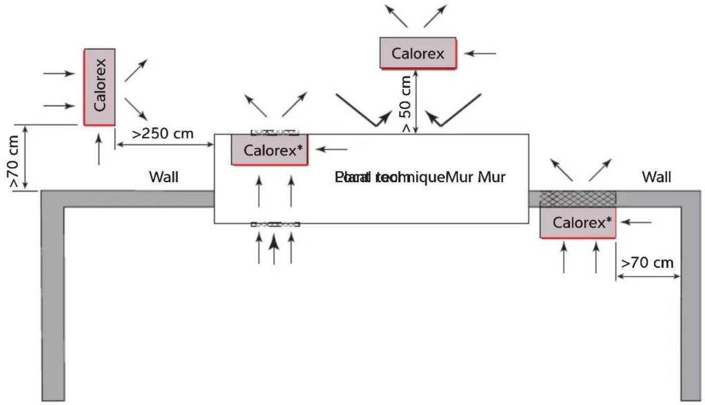
Possible positions of a Calorex heat pump
Unit 12. Galliford Road
Maldon CM9 4XD
United Kingdom
+44(0)1621856611
DECLARATION OF CONFORMITE
Noscertifonsparla presentequelesmodeledanthermsuivants:
Unit 12, Galliford Road
Maldon CM9 4XD
United Kingdom
t.44(0)1621856611
Dantherm GmbH
Oststraße 148
22844 Norderstedt
Germany
+49405268790
Dantherm S.p.A.
Via Gardsana 11
37010 Pastrengo (VR)
Italy
t+390456770533
Dantherm Sp. zo.o.
ul. Magazynowa 5a
62-023 Gadjki
Poland
t.48616544000
Dantherm SP S.A.
C/Calabozos 6
(Poligono Industrial)
28108 Alcobendas, Madrid
Spain
t+34916614500
Dantherm SAS
23 rue Eugène Henaff
69694 Venissieux Cedex
France
t+33478471111
Dantherm AS
Lokkaseveien 26
3138 Skallested
Norway
t.14733351600
Dantherm AB
Fridhemsvagen 3
602 13 Norrkoping
Sweden
t. +46 (0)11 19 30 40
Dantherm LLC
Transportnaya 22/2
142800, Stupino
Moscow
Russia
t.+7(495)6424448
MCS China
Unit 2B, No. 512
Yunchuan Road
Baoshang, Shanghai, 201906
China
+862161486668
Termigo S.L
Manufacturers details:
Dantherm Ltd.
Unit 12, Galliford Road
Maldon CM9 4XD
United Kingdom
t.+44(0)1621856611
e. service.department@dantherm.com
I-PAC / I-PAC+ Inverter-Wärmpumpen
IPT 8, 12, 16, 22, 28
Watanauindus contractors
$$ \begin{array}{l} 2 \times 1 \frac {1}{2}, \ 2 \times 5 0 m m \ \end{array} $$
Bpilngge kit
2.3 OPTIONALES ZUBEHÖR
Unit 12. Galliford Road
Maldon CM9 4XD
United Kingdom
+44(0)1621856611
Unit 12, Galliford Road
Maldon CM9 4XD
United Kingdom
t+44(0)1621856611
Dantherm GmbH
OststraBe 148
22844 Norderstedt
Germany
t. +49 40 526 8790
Dantherm S.p.A.
Via Gardesana 11
37010 Pastrengo (VR)
Italy
t+390456770533
Dantherm Sp.z o.o.
ul. Magazynowa 5a
62-023 Gadki
Poland
t. +48 61 65 44 000
Dhantherm SP S.A.
C/Calabozo 6
(Poligono Industrial)
28108 Alcobendas, Madrid
Spain
t+34916614500
Dantherm SAS
23 rue Eugène Henaff
69694 Venissieux Cedex
France
+33478471111
Dantherm AS
Lokkedsveien 26
3138 Skallestad
Norway
t.+4733351600
Dantherm AB
Fridhemsvagen 3
602 13 Norrköping
Sweden
t,+46(0)11 193040
Dantherm LLC
Transportnaya 22/2
142800, Stupino
Moscow
Russia
t.+7(495)6424448
MCS China
Unit 28, No.512
Yunchuan Road
Baoshang, Shanghai, 201906
China
t. +8621 61486668
Termigo S.L
Manufacturers details:
Pantherm Ltd.
Unit 12, Galliford Road
Maldon CM9 4XD
United Kingdom
t.+44(0)1621856611
e. service.department@dantherm.com
Bombas de calor inverter I-PAC / I-PAC+
IPT 8, 12, 16, 22, 28
service.department@dantherm.com
I-PAC (modelos IPT X): -5-43 °C
I-PAC+ (modelos IPT Y): -10-43°C
Obtain verification code
c. Crear familia


Unit 12. Galliford Road
Maldon CM9 4XD
United Kingdom
+44(0)1621856611
Unit 12, Galliford Road
Maldon CM9 4XD
United Kingdom
t.+44(0)1621856611
Dantherm GmbH
OststraBe 148
22844 Norderstedt
Germany
t. +49 405268790
Dantherm S.p.A.
Via Gardesana 11
37010 Pastreno (VR)
Italy
t+390456770533
Dantherm Sp. zo.o.
ul. Magazynowa 5a
62-023 Gadki
Poland
t.+48616544000
Dantherm SP S.A.
C/Calabozo 6
(Poligono Industrial)
28108 Alcobendas, Madrid
Spain
t+34916614500
Dantherm SAS
23 rue Eugène Henaff
69694 Venissieux Cedex
France
t. +33478471111
Dantherm AS
Lokkeseveien 26
3138 Skallestad
Norway
t.+4733351600
Dantherm AB
Fridhemsvagen 3
602 13 Norrkoping
Sweden
t. +46 (0)11 19 30 40
Dantherm LLC
Transportnaya 22/2
142800, Stupino
Moscow
Russia
t.+7(495)6424448
MCS China
Unit 2B, No. 512
Yunchuan Road
Baoshang, Shanghai, 201906
China
t.+862161486668
Termigo S.L
Manufacturers details:
Dantherm Ltd.
Unit 12, Galliford Road
Maldon CM9 4XD
United Kingdom
t.+44(0)1621856611
e. service.department@dantherm.com
IPT 8, 12, 16, 22, 28
Androdipdksecdoicareka from

iOS p125sectionaldeathfrom

Unit 12. Galliford Road
Maldon CM9 4XD
United Kingdom
+44(0)1621856611
Unit 12, Galliford Road
Maldon CM9 4XD
United Kingdom
t. +44 (0)1621 856611
Dantherm GmbH
Oststraße 148
22844 Norderstedt
Germany
+49405268790
Dantherm S.p.A.
Via Gardesana 11
37010 Pastrengo (VR)
Italy
+390456770533
Dantherm Sp. zo.o.
ul. Magazynowa 5a
62-023 Cadjki
Poland
t. +48616544000
Dantherm SP S.A.
C/Calabozos 6
(Poligono Industrial)
28108 Alcobendas, Madrid
Spain
t. +34 91 661 45 00
Dantherm SAS
23 rue Eugène Henaff
69694 Vénissieux Cedex
France
t+33478471111
Dantherm AS
Lokkaeasveien 26
3138 Skallestad
Norway
t+4733351600
Dantherm AB
Fridhemsvagen 3
602 13 Norrköping
Sweden
t.+46(0)11 19 30 40
Dantherm LLC
Transportnaya 22/2
142800, Stupino
Moscow
Russia
l.+7(495)6424448
MCS China
Unit 2B, No.512
Yunchuan Road
Baoshang, Shanghai, 201906
China
t.+862161486668
Termigo S.L
Manufacturers details:
Dantherm Ltd.
Unit 12, Galliford Road
Maldon CM94XD
United Kingdom
t.+44(0)1621856611
e. service.department@dantherm.com
IPT 8, 12, 16, 22, 28
Mawterzantipdyonnectors
2 × 1%
2 × 50 ~mm
Deatnagcklitywowy
2.3 OPCJONALNE AKCESORIA
I-PAC (modele IPT X): -5-43°C
I-PAC+ (modele IPT Y): -10-43°C
Unit 12, Galliford Road
Maldon CM9 4XD
United Kingdom
+44(0)1621856611
Unit 12, Galliford Road
Maldon CM9 4XD
United Kingdom
t.+44(0)1621856611
Dantherm GmbH
Oststraße 148
22844 Norderstedt
Germany
+49405268790
Dantherm S.p.A.
Via Gardesana 11
37010 Pastrengo (VR)
Italy
t+390456770533
Dantherm Sp. zo.o.
ul. Magazynowa 5a
62-023 Gadjki
Poland
t.+48616544000
Dantherm SP S.A.
C/Calabozos 6
(Poligono Industrial)
28108 Alcobendas, Madrid
Spain
t,+34916614500
Dantherm SAS
23 rue Eugène Henaff
69694 Venissieux Cedex
France
t.+33478471111
Dantherm AS
Lokkasevien 26
3138 Skallestad
Norway
t+4733351600
Dantherm AB
Fridhemsvagen 3
602 13 Norrkoping
Sweden
t. +46 (0)11 19 30 40
Dantherm LLC
Transportnaya 22/2
142800, Stupino
Moscow
Russia
t.+7(495)6424448
MCS China
Unit 2B, No.512
Yunchuan Road
Baoshang, Shanghai, 201906
China
t.+862161486668
Termigo S.L
Manufacturers details:
Dantherm Ltd.
Unit 12, Galliford Road
Maldon CM9 4XD
United Kingdom
t. +44 (0)1621 856611
e. service.department@dantherm.com
Bombas de calor de invorsor I-PAC/I-PAC+
IPT 8, 12, 16, 22, 28
31 POSICIONAMENTO E FLUXO DE AR 000000000000000000000000000000000000000000000000000000000000000000000000000
32TIPDEFREERIGERANTEFLOCAL
DE INSTALAÇÃO 1222222222222222222222222222222222222
3CIRCUITO DE AGUA DA PISCINA DNEE
34 CANALIZACOs
35 VERIFICAÇOES INICIAIS
PARAO INVERNO 17
ACOES A EVITAR (OPERACAO E MANUSEAMENTO):
I-PAC (modelos IPT X): -5-43 °C
I-PAC+ (modelos IPT Y): -10-43 °C
Área m^2 3,16,910,334,06,912,334,062,0
minima
Confirm Indicator Rapidly Blink
Confirm
e. Funcimiento
Unit 12, Galliford Road
Maldon CM9 4XD
United Kingdom
+4401621856611
Dantherm GmbH
OststraBe 148
22844 Norderstedt
Germany
t+49405268790
Dantherm S.p.A.
Via Gardesana 11
37010 Pastrengo (VR)
Italy
L+390456770533
Dantherm Sp. zo.o.
ui. Magazynowa 5a
62-023 Gadki
Poland
t+48616544000
Dantherm SP S.A.
C/Calabozo 6
(Polgono Industrial)
28108 Alcobendas, Madrid
Spain
t+34916614500
Dantherm SAS
23 rue Eugène Henaff
69694 Vénissieux Cedex
France
t+33478471111
Dantherm AS
Lokkasevien 26
3138 Skallested
Norway
t+4733351600
Dantherm AB
Fridhemsvagen 3
602 13 Norrkoping
Sweden
t. +46 (0)11 19 30 40
Dantherm LLC
Transportnaya 22/2
142800, Stupino
Moscow
Russia
t+7(495)6424448
MCS China
Unit 28, No. 512
Yunchuan Road
Baoshang,Shanghai,201906
China
t.+862161486668
Termigo S.L
Manufacturers details:
Dantherm Ltd.
Unit 12, Galliford Road
Maldon CM9 4XD
United Kingdom
t.+44(0)1621856611
e. service.department@dantherm.com
- HEALTH AND SAFETY WARNING
- CONTENTS
- HEALTH AND SAFETY WARNING 2
- INTRODUCTION
- FOREWORD
- WARNINGS
- REFRIGERANT SAFETY:
- Do not attempt to work on the equipment by yourself.
- ACTIONS TO AVOID (OPERATION AND HANDLING):
- IN CASE OF FIRE:
- LOCATION REQUIREMENTS:
- INSTALLATION:
- AIRFLOW:
- ELECTRICAL SAFETY:
- HEAT PUMP MALFUNCTION:
- MAINTENANCE:
- DISPOSAL:
- ABOUT YOUR HEAT PUMP
- TRANSPORTATION
- Do not lift the heat pump by the water inlet or outlet connections.
- ACCESSORIES
- OPTIONAL ACCESSORIES
- FEATURES
- OPERATING CONDITIONS AND RANGE
- OPERATING MODES
- INSTALLATION
- POSITIONING AND AIRFLOW
- Airflow - general principles
- REFRIGERANT TYPE AND INSTALLED LOCATION
- INTERPRETATION
- Pool outside and heat pump outside:
- Pool outside and heat pump inside a plant room:
- Pool inside and heat pump outside:
- Pool inside and heat pump inside a plant room, isolated from the pool hall:
- Pool inside and heat pump inside a plant room, ventilated to the pool hall:
- POOL WATER CIRCUIT
- PLUMBING
- IMPORTANT
- INITIAL CHECKS
- ELECTROLYTIC CORROSION IN SWIMMING POOLS
- ELECTRIC WIRING AND SUPPLY
- CONNECTING THE HEAT PUMP TO THE POWER SUPPLY
- POOL PUMP SYNCHRONISATION TERMINALS P1 AND P2
- INSTALLING THE OPTIONAL REMOTE CONTROLLER
- OPERATING INSTRUCTIONS
- a. Screen lock
- b. Power on
- c. Temperature setting
- d. Mode selection
- e. Speed Mode selection
- f.Wi-Fi
- g. Defrosting
- USING THE APP
- a. APP Download b. Account registration
- c. Create family
- d. APP Pairing
- Please make sure you are connected to the Wi-Fi.
- e. Operation
- f. Share devices to your family members
- Notes:
- USING THE OPTIONAL REMOTE CONTROLLER
- THE KEY PAD
- OPERATING INSTRUCTIONS
- a. Power On & Power Off
- b. Temperature Setting
- c) Mode selection
- c. Defrosting
- TESTING
- Inspect the heat pump before use
- HEAT PUMP MALFUNCTION
- WARNING: Isolate heat pump electrically, and wait 3 minutes before removing panels or entering heat pump.
- Fault Reason Solution
- PROTECTION CODES
- FAULT CODES
- MAINTENANCE
- TROUBLE SHOOTING COMMON FAULTS
- Requirements for service personnel
- DIMENSIONS
- WINTERISATION PROCEDURE
- WARNING. Isolate machine before opening! As heat pump embodies electrical and rotational equipment, it is recommended for your own safety that a competent person carries out the following procedure.
- If is procedure is not adopted and frost or corrosion damage results en e warranty will become invalid
- START UP PROCEDURE AFTER WINTERISATION
- WARRANTY CONDITIONS
- DECLARATION OF CONFORMITY
- DANTHERMGROUP
- DECLARATION OF CONFORMITY
- Conforms with
- Don Kempster
- Dantherm A/S
- Dantherm Ltd.
- Dantherm GmbH
- Dantherm S.p.A.
- Dantherm Sp. zo.o.
- Dantherm SP S.A.
- Dantherm SAS
- Dantherm AS
- Dantherm AB
- Dantherm LLC
- MCS China
- Termigo S.L
- DECLARATION OF CONFORMITE
- Manufacturers details:
- OPTIONALES ZUBEHÖR
- Dantherm Sp.z o.o.
- Dhantherm SP S.A.
- Pantherm Ltd.
- Bombas de calor inverter I-PAC / I-PAC+
- IPT 8, 12, 16, 22, 28
- c. Crear familia
- OPCJONALNE AKCESORIA
- ACOES A EVITAR (OPERACAO E MANUSEAMENTO):
- e. Funcimiento
Brand : Calorex
Model : I-PAC
Category : Heat pump