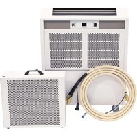
ACT-7 - Air Conditioning Dantherm - Free user manual and instructions
Find the device manual for free ACT-7 Dantherm in PDF.


| Product type | Portable split air conditioner (indoor unit + outdoor heat exchanger) |
| Brand | Dantherm |
| Model | ACT-7 |
| Cooling capacity (max.) | 7.0 kW |
| Power supply | 230 V / 50 Hz single-phase |
| Recommended fuse | 16 A (EU) / 13 A (UK) |
| Rated current | 11.2 A (EU) / 11 A (UK) |
| Power consumption (nominal) | 2.6 kW (EU) / 2.5 kW (UK) |
| Indoor airflow | 930 to 1,310 m³/h (continuous variation) |
| Indoor sound level (at 3 m, max speed) | 56 dBA |
| Refrigerant | R407C / 880 g (GWP = 1774, CO2 equivalent = 1.561 t) |
| Operating range - ambient temperature | 8 to 35 °C |
| Operating range - outdoor | 0 to 40 °C (EU) / 0 to 35 °C (UK) |
| Max. interconnecting line length | 30 m (max. height 10 m) |
| Weight of outdoor heat exchanger | 18.5 kg (EU) / 18 kg (UK) |
| Main functions | Cooling, ventilation only, standby, automatic defrost, temperature setting (5-30 °C), continuous fan speed adjustment, temperature display, high/low pressure alarms, condensate tank full indicator, optional PIN code |
| Routine maintenance | Weekly check of water/glycol fluid level; monthly cleaning of air filter and outdoor heat exchanger |
| Safety | For competent personnel only; do not use without connected heat exchanger; do not lift indoor unit by handle; always transport in vertical position; use gloves when handling water/glycol mixture |
| Included accessories | Interconnecting line (5-30 m), power cord (2 m), support chains for suspension, drain hose |
Frequently Asked Questions - ACT-7 Dantherm
User questions about ACT-7 Dantherm
0 question about this device. Answer the ones you know or ask your own.
Ask a new question about this device
Download the instructions for your Air Conditioning in PDF format for free! Find your manual ACT-7 - Dantherm and take your electronic device back in hand. On this page are published all the documents necessary for the use of your device. ACT-7 by Dantherm.
USER MANUAL ACT-7 Dantherm
| Table of content | Introduction 2 Product description 3 Overall description 3 Installation 5 Location consideration 5 Handling and set-up. 7 Dismantling 11 Operation 12 User interactions 12 Service Guide 16 Preventative maintenance 16 Trouble shooting 17 |
| This manual | This is the service manual for the Dantherm ACT 7 air conditioner unit. Part number of this user manual is: 054380. |
| Target group | As the air conditioner contains electrical and rotational equipment, it is recommended that ONLY competent persons carry out any work on this type of device. This device should only be operated by a competent adult who has read and understood these instructions. Never operate this device if you are ill, feeling tired or under the influence of alcohol or drugs. |
| Apart from the replacement of air filters and exterior cleaning of the system, any kind of maintenance will require the use of trained personnel. | |
| Safety precautions | It is important to acknowledge the correct operating procedures for the air conditioner and all of its safety precautions. Dantherm accepts no liability with regards to loss of business or personal injury as a consequence of failing to abide by safety procedures. |
| Copyright | Copying of this service manual, or part of it, is forbidden without prior written permission from Dantherm. |
| Reservations | Dantherm reserves the right to make changes and improvements to the product and the service manual at any time without prior notice or obligation. |
| Recycling | This unit is designed for long term durability. When total lifetime ends, the unit should be recycled according to national rules and with high environmental protection considerations. |
| WARNING | Type and source of hazard This symbol in connection with the word "Warning" warns of a risk involving severe injury. • Measures to avert danger or immediate measures if the risk occurs are described in this way |
| CAUTION | Type and source of hazard This symbol in connection with the word "Caution" warns of a risk of minor or moderate injury and material damage. • Measures to avert danger or immediate measures if the risk occurs are described in this way |
| NOTICE | In connection with this symbol you will find further tips and information concerning the use of the device. |
Product description
Overall description
Designated use
The ACT 7 is a portable air conditioner intended for small-scale temporary cooling, and can be used in many different places such as rental companies, event organization, workshops and offices.
ACT 7 system connection
Description Illustration
The ACT 7 comprises a room unit and external heat excha
The interconnecting line (max 30m which connects the two parts together includes two water pipes, condensed waste water pipe and an electrical supply power cord. Both ends of the water pipes are fitted with 'quick connect' couplings that open on connection but reseal to become water tight on disconnection.
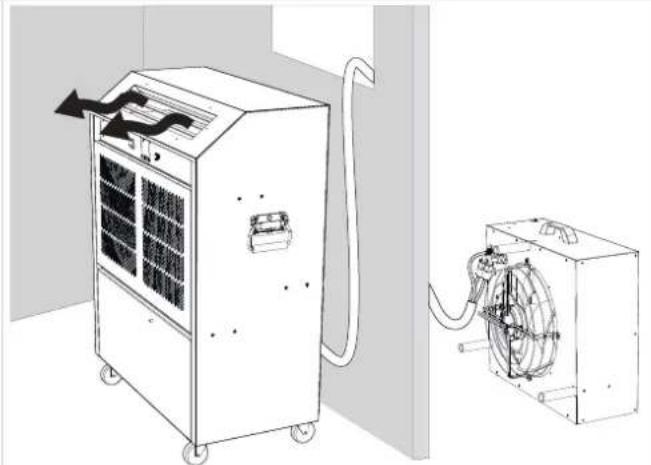
Fig.1
Illustration (Room unit)
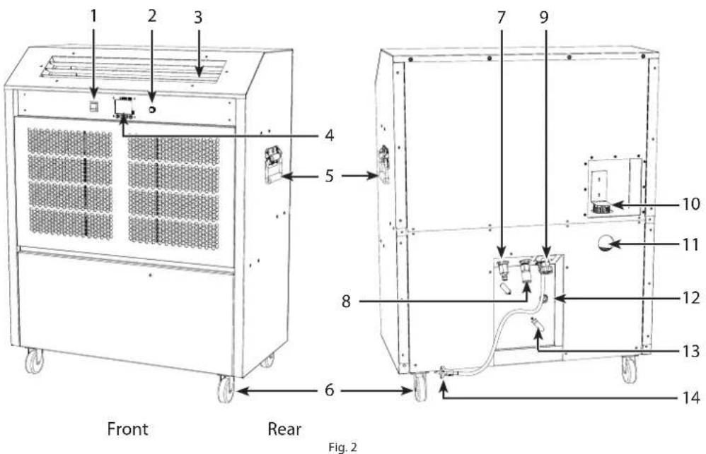
| Pos. Description Pos. Description | |
| 1 Mode switch 8 Water pipe coupling (IN) | |
| 2 Fan speed control dial 9 Electrical supply connection to heat exchanger | |
| 3 Grille 10 Tank filler | |
| 4 Display | 11 Inspection window |
| 5 Handle for moving the unit | 12 Condensed waste water outlet |
| 6 Wheels | 13 Cable keeper |
| 7 Water pipe coupling (OUT) | 14 Supply cord (2 m) |

Illustration (Heat exchanger)
Front

Fig. 3
Pos. Description Pos. Description
| 1 Support chain 5 Drain pipe | |
| 2 Carrying handle 6 Water pipe coupling (IN) | |
| 3 Electrical connection 7 Fan | |
| 4 Water pipe coupling (OUT) 8 Spacer |
Data sheet
Specification Unit ACT 7 EU ACT 7 UK
| Cooling capacity (max)1 | kW 7,0 | 7,0 | |
| Power Supply | V/Hz | 230/1ph/50 | |
| Power plug | CEE 7/7 | UK mains | |
| Fuse | A | 16 | 13 |
| Nominal current | A | 11,2 | 11 |
| Power consumption (nominal) | kW 2,6 | 2,5 | |
| Airflow internal (stepless variable) | m3/h | 930-1310 | |
| Sound level (3 metres indoor - max. speed) | dBA | 56 | |
| Operating range - room temperature | °C | 8-35 | |
| Operating range - outdoor | °C | 0-40 | 0-35 |
| Refrigerant / charge | gram | R407C/ 880 | |
| GWP (Global Warming Potential) | 1774 | ||
| CO2equivalent | ton | 1,561 | |
| Max length/height between in- and outdoor unit | m | 30/ 10 | |
| Surface powder coated | RAL7047 Gloss 85 smooth | ||
| Outdoor unit | |||
| Sound level (3 metres - max speed) | dbA | 55 | 52 |
| Weight | kg | 18,5 | 18 |
1: Outside conditions 28^ / 60% RH
Installation
Location consideration
Sitting (Room unit)
Good and correct air flow is, perhaps, the single most important aspect of satisfactory use of portable air conditioners. Some examples of how to place the room unit in the most common situations are illustrated in the table below. If in doubt seek the advice of your supplier.
| Installation Description Illustration options | ||
| one unit Ideally the ACT 7 room unit should be posi- tioned in the middle of the shortest wall in the room blowing down the length of the room. | x x | |
| two units If there is more than one ACT 7 in the same area, then they would normally be posi- tioned side by side, and equally spaced along the long wall, all pointing in the same direction. | x x x | |
| Around the perimeter | Sometimes it may be necessary to position units around the pe- rimeter of an area but, in this case, great care should be taken to avoid one unit blow- ing cold air straight into another which will adversely affect oper-a- tion. | x x x x |

NOTICE
Also be aware of the following:
- the room unit has to be sited on firm level ground.
- the room unit has to be located away from any possible unauthorised interference.
- Condensation on the outside of the room unit may appear, when the room unit operates at low indoor temperatures as e.g. 10^ and high relative humidity (80%) at the same time. If operated under these conditions the units side plate should be wiped off regularly in order to avoid water on the floor.
Siting (Heat exchanger)

NOTICE
The heat exchanger must be sited external to the area being cooled and, preferably outside.
Consider especially the potential of dripping water when positioning the external heat exchanger and find a location, where debris can't get into the air flow of the heat exchanger.
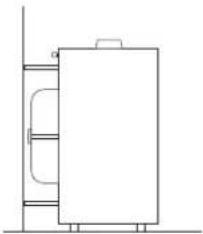
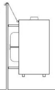
a. The heat exchanger can stand freely on a flat surface or
b. It may be hung, in the upright position, from a window-sill or balcony. Use the chains provided to support the heat exchanger.
NB: When the heat exchanger is hanging, it must be fixed with a suitable hook in the wall.
a
b
Handling and set-up
Handling
Follow these instructions when handling the room unit:

CAUTION
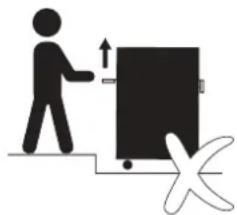
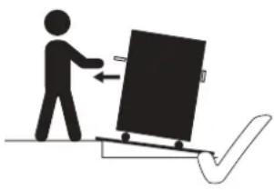
Risk of plate deformation, damaging unit and human injuries
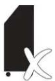
- Do NOT lift the room unit at the handle
- Use handle ONLY to push and drag the room unit
- Use a ramp to get the ACT 7 unit over a curb or alike.

CAUTION
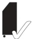
Risk of damaging the cooling circuit when laying down the room unit
Oil from the compressor can get inside and damage the cooling circuit, if the unit is laid down.
- Do NOT lay the room unit down
- Always transport the room unit in an upright position

Precautions

CAUTION
Avoid getting the water/glycol mixture on your skin and clothes
The water/glycol mixture contains anticorrosive substances, which is noxious and can lead to skin irritation. The substance can be difficult to remove from clothes.
- Use gloves for connecting and disconnecting the interconnecting line.
- If the glycol/water mixture is spilled on your skin, wash thoroughly with water and soap.
- Wear work clothes while connecting and disconnecting the ACT 7.

Check the fluid level
Check always the fluid level of the ACT 7 room unit before starting up the unit.
Look through the inspection window (use a flashlight, if necessary) and check, if the fluid level is between MIN and MAX level. Top up the fluid, if the level is below MIN.
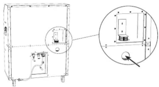
Follow the steps below, if you need to fill up the fluid level.
step Action Illustration
1 Ensure the ACT 7 is running in cooling mode, before removing the filler cap.
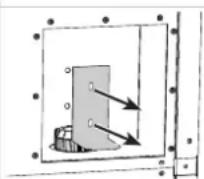
2 Loosen the screws and remove the security plate of the filler cap.
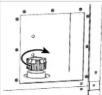
3 Slowly remove the filler cap
4 Top up the tank with the correct anti-freeze (33%) and water mixture until the fluid level is between min. and max. level (check the level through the inspection window).
Be aware not to mix different types of antifreeze, in order to protect the system properly.
(Original specification is ethylene glycol based antifreeze, containing rust/corrosion inhibitors, suitable for aluminium systems, 33% giving protection to -20^ . This specification will protect the entire glycol/water circuit down to -16^(-5^) .)

5 Mount the cap and security plate again.
Connecting room unit to heat exchanger
Step Description Illustration
1 Use the interconnecting line (5-30m) to connect the ACT 7 room unit to the heat exchanger.
NB: The interconnecting line should be routed carefully to avoid any possibility of kinking or unnecessary restrictions to the flow of water. The line will be more likely to kink when warm.
2 Connect the condensate drain to the ACT 7 room unit.
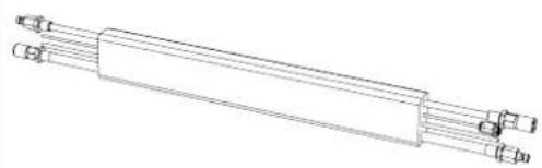
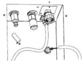
3 Connect the condensate drain to the heat exchanger by pushing the clear hose ends into the grey connector.
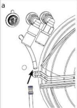
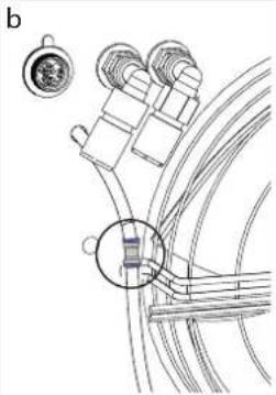
4 Connect the pipes to the a. heat exchanger and b. room unit
Pull the coupling of the female pipe adapter back in order to connect the pipes.
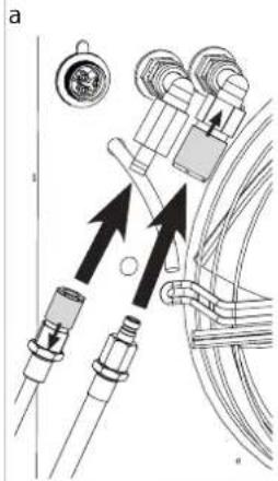
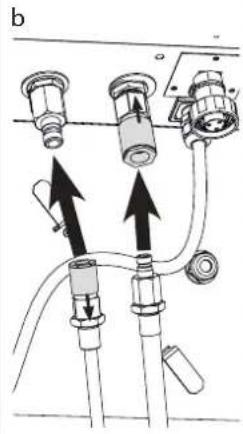

Be prepared with an old cloth or alike to wipe the water/glycol mixture up, since it will spill a bit, when the pipes are connected.
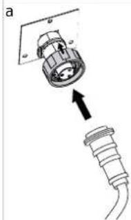
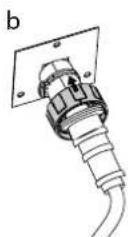
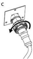
5 a. Connect the heat exchanger power cord to the ACT 7 room unit using the socket provided. b. Push the locking ring towards the machine. c. Turn locking ring clockwise to lock the connection. Repeat a + b + c when connecting the power cord to the heat exchanger.
Electrical supply
Plug the room unit into a power socket.
- As standard the ACT 7 requires a fused electrical supply (UK 13A, Europe 16A) rated at 230 Volts, 1N , 50Hz. The ACT 7 is equipped with a UK plug (CEE 7/7) as standard.
If an extension cable is used the following specifications must be complied to.
| Extension cable (length) | Extension cable (min. width) |
| max. 10 m 2,5mm | 2 |
| 10 m and more 4,0mm | 2 |

CAUTION
Improper use of cables or using insufficient cable type can cause short circuit and fire hazard
- If the supply cord is damaged, it must be replaced by the manufacturer, its service agent or similarly qualified persons in order to avoid a hazard.
- Use extension cable with the right specification (be aware that most domestic proprietary extension cables are 1,5mm^2 - this is not sufficient)
- If the cable is on a 'cable drum' then ensure that it is completely unwound in accordance with the manufacturer's instructions
Dismantling
Disconnecting/ turning off
Follow the steps below in order to disconnect the ACT 7.
Failure to follow the procedure may result in excess water being retained in the system which may spill when the ACT 7 is moved.
Step Action Illustration
1 Switch to standby mode. Keep the unit in this mode for at least 30 minutes in order to let the condensate pump drain the system.
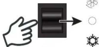
2 When you have waited for 30 minutes, you can disconnect: a. mains power to room unit and b. power cord between heat exchanger and room unit.
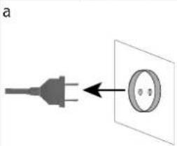
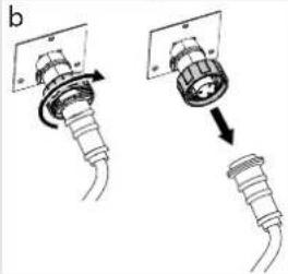
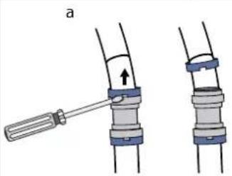
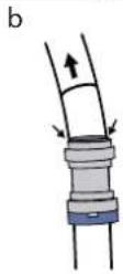
3 Disconnect drain hose from the heat exchanger: a. Use a screwdriver to remove the blue collet from the hose connector. b. Push darker grey ring in' and pull at the same time the hose to remove. Repeat step b to remove the hose from the room unit.
4 Disconnect pipes from a. room unit and b. heat exchanger Pull the coupling of the female pipe adapter back in order to disconnect the pipes.
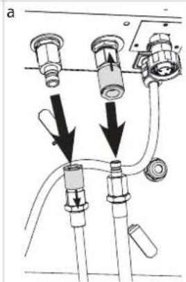
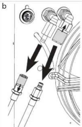

Be prepared with an old cloth or alike to wipe the water/glycol mixture up, since it will spill a bit, when the pipes are disconnected.
Operation
User interactions
General recommendation
Check condition of the device before use. If device is showing signs of damage contact your supplier immediately.

CAUTION
Operation without connected heat exchanger provokes an HP failure and can damage the recirculation pump
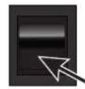


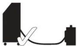
If the ACT 7 room unit is operated in air conditioning mode while the heat exchanger is disconnected, the room unit will enter a high pressure state and automatically shut down the unit. There is a risk of damaging the recirculation pump.

- The ACT 7 room unit must only be operated (specifically in Air Conditioning mode), when connected to the heat exchanger with the interconnecting line provided.
Adjusting the air flow direction
The air outlet at the top of the ACT 7 room unit is fitted with grilles that allow the angle of air outlet to be adjusted.
In conjunction with the fan speed control switch, the air velocity and direction can be carefully set up to obtain maximum coverage of the area being cooled without causing draughts.
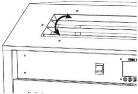
NB: An alternative top panel with twin 7^ ducts is available.

NOTICE
If the air flow is blocked an HP or LP failure can be provoked and shut down the unit
- Never put anything on top of the device or block the air in- and outlets.
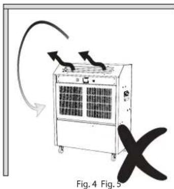
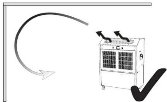
Fig. 4: Care should be taken to avoid outlet air being obstructed as this will cause the air to rebound around the device resulting in recirculation and incorrect control of the device.
Fig. 5: Ideally, the air should be directed to create a 'blanket' of cold air across the ceiling area allowing natural convection to drop the air over the whole area at very low velocity.
Control panel
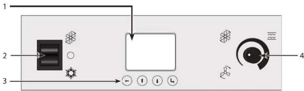
Fig.6
| Pos. Function Description | |
| 1 Display See display options on page 14. | |
| 2 Mode switch | Fan only • Ventilation without air conditioning |
| ○ Stand by • The device remains powered but will not operate | |
| Air Conditioning (A/C) • When the controller detects a cooling requirement, a timer will delay the compressor start for a minimum of one minute and a maximum of six minutes. | |
| 3 Navigation buttons | Return/ OK/ Save • Enter menu/ submenu: Press L for 2 seconds, then release • Confirm and save settings |
| ↑ ↓ Up & down • Toggle menu | |
| ← Back/cancel • Press ← to get out of a submenu/menu | |
| 4 Fan speed control dial Adjust the fan speed. Please note that there is a short delay between turning the dial and the fan speed increasing or decreasing. | |
Display
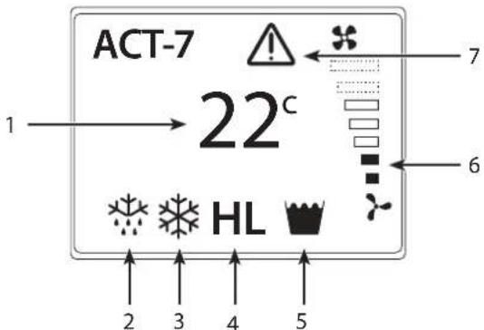
Fig. 7
| Pos. Display Description | |
| 1 Current temperature Measured sensor temperature. | |
| 2 Defrost (active) The ACT 7 runs the defrost mode when needed and automatically returns to cooling/fan only mode when finished. | |
| 3 Air Condition (active) The ACT 7 is in air condition mode. | |
| 4 Alarms (flashing): ·H = High pressure ·L = Low pressure | The alarm has to be reset (see "Menu overview" on page 15) when the error has been rectified (find help for trouble shooting on page 17). |
| 5 Tank full indicator (flashing) | The alarm resets itself and works as follows: 1. When the alarm appears the ACT 7 will continue to work for the next 30 seconds. 2. If the condensate tank has not been emptied, the pump continues to operate while the ACT 7 stops cooling. 3. When the condensate tank is emptied, the alarm will disappear and the ACT 7 will restart after a delay of minimum one minute and maximum six minutes. |
| 6 Fan speed Displaying the fan speed adjusted by the fan speed dial. | |
| 7 Overheat warning Indoor temperature is too high (above 35 °C). The symbol will disappear automatically, when the room temperature drops below 35°C and the ACT 7 starts up again. (see also "Trouble shooting" on page 17) | |
Menu overview
| Main menu Submenu | |
| Temperature ·Set the start temperature for the air conditioner (5-30℃). The value is set to 15℃ by default. | (NONE) |
| Reset alarm (use only, when alarm is visible on display and the underlying problem has been solved) ·When an alarm (H or L) is shown on the display and the error has been rectified, the alarm has to be reset in the submenu (HP fault/ LP fault) in order to start the unit up again. | HP fault ·See trouble shooting on page 17. |
| LP fault ·See trouble shooting on page 17. | |
| Advanced ·Access the submenus | Offset ·An offset(+/- 0-99) is used to calibrate the temperature shown on the main screen. ·This feature can be used, when e.g. ducting is connected and the temperature of the ventilated place is different from the temperature displayed. |
| Enable pin ·The pin code (1234) is disabled by default. When the pin is enabled, you have to type the pin code before you can change the settings. -1 = Enabling pin -0 = disabling pin | |
| Language ·The language is set to English by default. Change the language of the menu: - English - Français - Deutsche | |
Service Guide
Preventative maintenance
Introduction
Preventative maintenance is necessary at regular intervals if the unit has to function efficiently and if you want to ensure the expected lifetime of minimum 10 years.
Weekly
Check the fluid level every week and top up as needed (see detailed procedure in section "Check the fluid level" on page 7).
Monthly
The air inlet filter of the room unit and the inside of the heat exchanger must be kept clean in order to ensure best performance. Check once a month and clean as needed. Follow this procedure to perform the monthly service:
Step Action
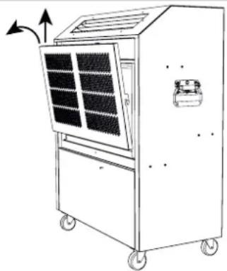
Inspect/ clean air filter
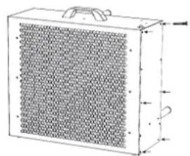
1 Remove the upper front plate by pushing it up and pulling it out.
2 The filter is fitted to the rear of the front plate and is held on with magnets. Remove the filter and check, if it is dirty. Vacuum clean excess dirt and wash the filter with soapy water, if needed.
3 Leave the filter to dry before refitting it and operating the ACT 7.
Inspect/clean heat exchanger
1 Loosen the screws and remove the side plate of the heat exchanger.
2 If needed: Carefully vacuum clean coarser dirt and wipe off the dust from the inside of the heat exchanger.
3 Reattach the side plate with screws.
Trouble shooting
Fault finding
| Symptoms Display Problem Possible cause Action required | ||||
| No air flow from room unit | OFF | Power (230V) connected but no function | Power outlet in wall is off/ disconnected | Turn on electricity and/or check mains fuse |
| Defect on electrical equipment/ cables | Call for an electrician. | |||
| Insufficient air flow from room unit | Normal display | Blocked air ways | Room unit has blocked air ways | Clean the air filter (see instruction on page 16) |
| No cooling | H | Unit is defrost-ing | Unit is defrosting in regular intervals (normal behaviour) | Do not adjust anything. Unit will return to normal operation after ten minutes. |
| Refrigeration system in danger for overheat | Indoor temperature too high (above 35 °C) | Connect a T-split hose and two outdoor heat exchangers to the same ACT 7. This will make the unit operate in higher temperatures. | ||
| High pressure state (NB: Resetting alarm needed - see page 15) | Too little water/glycol fluid in the system | Top up the ACT 7 room unit header tank with water/glycol mixture. (See instruction on page 7) | ||
| External heat exchanger has blocked air ways | Clean the fan and the coil with a vacuum cleaner or water and a brush. (see instruction on page 16) | |||
| kinked hoses | Check the interconnecting line for kinking and remove them | |||
| External heat exchanger unit mounted in very high ambient temperature | Move external heat exchanger to a cooler/ shaded place | |||
| Leak in the water/glycol system | Call for a service technician. | |||
| L | Low pressure state (NB: Resetting alarm needed - see page 15) | Room unit has blocked air ways | Clean the air filter of the room unit (see instruction on page 16) | |
| Loss of refrigerant Call | Call for a refrigeration engineer. | |||
| Condensate pump un- able to reduce water | Kinked hoses | Check the interconnecting line for kinking and remove them | ||
| The unit has been unplugged without beeing in standby mode for 30 min. | If the symbol has not disappeared after 30 min., the water has to be drained manually. Call for a service technician. | |||
Call for a service technician, if you can't solve the problem or the problem reoccurs. Only a competent electrician should attempt to rectify electrical supply problems. Only a competent refrigeration engineer should work on the refrigeration system.
Einführung
Inhaltsverzeichnis
Einführung. 20
Description Illustration
Aansluiting ACT 7 system
10 men langer 4,0 mm

VOORZICHTIG
- Product description
- Overall description
- Designated use
- ACT 7 system connection
- Description Illustration
- Illustration (Room unit)
- Installation
- Location consideration
- Sitting (Room unit)
- Siting (Heat exchanger)
- Handling and set-up
- Handling
- CAUTION
- Risk of plate deformation, damaging unit and human injuries
- Risk of damaging the cooling circuit when laying down the room unit
- Precautions
- Avoid getting the water/glycol mixture on your skin and clothes
- Check the fluid level
- step Action Illustration
- Connecting room unit to heat exchanger
- Step Description Illustration
- Electrical supply
- Improper use of cables or using insufficient cable type can cause short circuit and fire hazard
- Dismantling
- Disconnecting/ turning off
- Operation
- User interactions
- General recommendation
- Operation without connected heat exchanger provokes an HP failure and can damage the recirculation pump
- Adjusting the air flow direction
- NOTICE
- Control panel
- Menu overview
- Service Guide
- Preventative maintenance
- Introduction
- Weekly
- Monthly
- Step Action
- Trouble shooting
- Fault finding
- Einführung
- Inhaltsverzeichnis
- Aansluiting ACT 7 system
- VOORZICHTIG
Brand : Dantherm
Model : ACT-7
Category : Air Conditioning