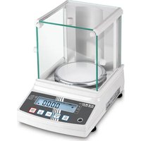
PNJ 600-3M - Scale Kern - Free user manual and instructions
Find the device manual for free PNJ 600-3M Kern in PDF.


User questions about PNJ 600-3M Kern
0 question about this device. Answer the ones you know or ask your own.
Ask a new question about this device
Download the instructions for your Scale in PDF format for free! Find your manual PNJ 600-3M - Kern and take your electronic device back in hand. On this page are published all the documents necessary for the use of your device. PNJ 600-3M by Kern.
USER MANUAL PNJ 600-3M Kern
natural_image
Digital laboratory balance scale with transparent casing and digital display (no visible text or symbols)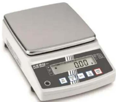
natural_image
Digital laboratory balance scale with digital display and control buttons (no visible text or symbols on the scale itself)GB Further language versions you will find online under www.kern-sohn.com/manuals
text_image
Technical diagram of an analytical balance with numbered components for identificationModelle d = 0,01g / 0,1 g:

text_image
Technical diagram of a digital balance or analog device with numbered components labeled for identification.Pos. Bezeichnung
text_image
KERN PNJ + TOL - ON OFF PRINT M SET F S TARE →0←natural_image
Line drawing of a digital balance scale with a small rectangular component on top (no text or symbols)Waage
natural_image
Simple line drawing of a square frame with rounded corners (no text or symbols)natural_image
Technical line drawing of a four-pronged mechanical component with mounting holes (no text or symbols)natural_image
Isometric line drawing of a 3D rectangular enclosure with internal components and mounting holes (no text or symbols)Windschutz (Modelle d = 0,001g) Montage s. Kap. 6.3
Betriebsanleitung
text_image
Diagram showing two mechanical components with labeled parts and directional arrows indicating motion or assembly.2
natural_image
Pure mechanical diagram showing a frame with screw holes and directional arrows, no text or symbols present.3
natural_image
Technical line drawing of a mechanical assembly with an inset detail showing a close-up view of a component (no text or symbols present)4
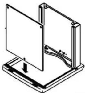
→ Frontplatte befestigen.
natural_image
Isometric line drawing of a mechanical assembly with a rectangular frame and base plate (no text or symbols)text_image
Technical diagram showing a mechanical assembly with labeled component M4 and an inset view of a bracket component.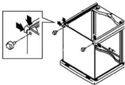
text_image
Technical diagram showing a mechanical assembly with a magnified inset of a tool interacting with a bracket, likely illustrating a turning or cutting process.6
natural_image
Isometric line drawing of a 3D cube with internal panels and directional arrows, no text or symbols present7
natural_image
Isometric line drawing of a mechanical housing with two vertical supports and a central frame (no text or symbols)9
natural_image
Technical line drawing of a mechanical assembly with an inset showing a close-up of a component detail (no text or symbols present)11
natural_image
Close-up of a white plastic mechanical component with internal components and mounting holes (no visible text or symbols)natural_image
Illustration of a digital laboratory balance scale with a circular component above it (no text or symbols)Modelle d = 0,001g
natural_image
Line drawing of a digital balance scale with an open lid and control panel (no text or symbols)Modelle d = 0,01g / 0,1 g
⇒ Windschutz installieren (nur Modelle d = 0,001g).
natural_image
Line drawing of a mechanical setup with a cube and digital scale, showing a downward trend from top to bottom (no text or symbols)natural_image
Technical line drawing of a mechanical device with two views showing internal components and directional arrows (no text or symbols)natural_image
Line drawing of a digital balance scale with two circular gauges and a pointer, no text or symbols present.Fußschrauben
natural_image
Technical line drawing of a mechanical device with mounting base and wiring (no text or symbols)Modelle d = 0,001g
natural_image
Line drawing of a portable electronic device with attached electrical outlet (no text or symbols)Modelle d = 0,01g / 0,1 g
natural_image
Line drawing of a hand pressing down on a tiered device (no text or symbols)natural_image
Simple line drawing of a hand pressing down on a cylindrical object (no text or symbols)natural_image
Technical line drawing of a device rear panel with labeled components (no text or symbols beyond labels)Modelle d = 0,001g

natural_image
Technical line drawing of a mechanical device with labeled component '3' (no text or symbols beyond label)Modelle d = 0,01g / 0,1 g
natural_image
Technical line drawing of a mechanical component with a labeled part (3), no text or symbols present.text_image
SET →0← 0.0 g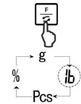
flowchart
graph TD
    A["Hand pressing F"] --> B["g"]
    B --> C["Pcs"]
    C --> D["lb"]
    D --> B
    style A fill:#f9f,stroke:#333
    style B fill:#ccf,stroke:#333
    style C fill:#cfc,stroke:#333
    style D fill:#fcc,stroke:#333
flowchart
graph TD
    A["SET"] --> B["M"]
    B --> C["Pcs"]
    C --> D["M 0.0 1.0"]
text_image
Pcs M on 30text_image
SET Pcs M on 30 Pcs M 60text_image
SET Pcs M 60text_image
+ TOL - ° 93.73 g 0 I I I Ftext_image
TOL + - 100.73g 0 I I I Ftext_image
+ TOL - 0 I I I F 107.03gtext_image
+ TOL - ° 93.73 g 0 I I I Ftext_image
TOL - 0 I I I F 100.00 gtext_image
0 I I I F 0.00 g SET L.SETtext_image
H.SET PRINT M 0 I I I F 105.00gtext_image
+ TOL - 0 I I I F ° 93.73 gtext_image
TOL 100.73gtext_image
+ TOL - 0 I I I F 107.03gtext_image
0 I I I F 0.00 g SET L.SET 70.00 g TARE →0← 70.00 g 0 I I I F 95.00 gtext_image
SET 13:45.27 23:45.27 23:45.27 DATE 15.10.14 F 0.0 gtext_image
TARE →0← F SETtext_image
TARE →0← F SETtext_image
SET →0← 0.0 gtext_image
SET →0← 0.0 gOperating instructions
Precision balance
Contents
1 Technical data.... 3
1.1 Dimensions....5
2 Appliance overview 6
2.1 Keyboard overview 7
2.2 Overview of display 8
3 Basic instructions....9
3.1 Intended use....9
3.2 Improper Use 9
3.3 Warranty 9
3.4 Monitoring of Test Resources....10
4 Basic Safety Precautions.... 10
4.1 Pay attention to the instructions in the Operation Manual.... 10
4.2 Personnel training....10
5 Transport and storage.... 10
5.1 Testing upon acceptance 10
5.2 Packaging / return transport 10
6 Unpacking, Setup and Commissioning 11
6.1 Installation Site, Location of Use 11
6.1.1 Scope of delivery / serial accessories: 12
6.2 Assemble windshield (only models d = 0.001g)....13
6.3 Assembly, placing and levelling 19
6.4 Mains connection....21
6.5 Initial Commissioning....22
6.5.1 Models PNJ 22
6.5.2 Models PNS 23
6.6 Connection of peripheral devices 23
6.7 Adjustment....24
6.7.1 Adjustment with internal weight (only models PNJ) 25
6.7.2 Adjustment with external weight (only models PNS) 26
6.8 Verification....27
7 Basic Operation 29
7.1 Start-up 29
7.2 Switch into stand-by mode 29
7.3 Zeroing....30
7.4 Simple weighing 30
7.5 Unity change....31
7.6 Weighing with tare 33
7.6.1 Taring....33
7.6.2 Multiple tare 34
8 Menu 35
8.1 Menu [function] 35
8.1.1 Navigation in the menu 35
8.1.2 Menu overview 36
8.2 Menu [Function2] 39
8.2.1 Navigation in the menu....39
8.2.2 Menu overview 39
9 Applications 40
9.1 Parts counting....40
9.2 Percent determination 43
9.3 Weighing with tolerance range 45
9.3.1 Enable function / settings in menu 46
9.3.2 Tolerance check after setting the limit values by weighing 48
9.3.3 Tolerance check after numeric input of the limit values 50
10 General functions 52
10.1 Zero-tracking 52
10.2 Settings for Stability and Response 53
10.3 Show software status 54
10.4 Switch-off background illumination of the display automatically 55
10.5 Setting date / time....56
10.5.1 Setting time 56
10.5.2 Setting date 58
10.6 Set date format 60
11 RS232C-interface 61
11.1 General hints 61
11.2 Printer operation 64
11.2.1 Edit an ISO/GLP/GMP-conform adjustment log (only models PNJ) 64
11.2.2 Protocol output with current date / time 65
11.3 Data output 67
11.3.1 Data transmission format 67
11.3.2 Description of data 69
11.3.3 Output examples 71
11.4 Remote control instructions 72
11.5 Response formats 73
12 Servicing, maintenance, disposal 74
12.1 Cleaning....74
12.2 Servicing, maintenance 74
12.3 Disposal 74
13 Instant help....75
14 Error messages.... 76
15 Declaration of conformity 77
1 Technical data
| KERN | PNJ 600-3M | PNJ 3000-2M | PNJ 12000-1M |
| Weighing range (max) | 620 g | 3200 g | 12000 g |
| Readability (d) | 0.001 g | 0.01 g | 0.1g |
| Minimum load (Min) | 0.02 g | 0.5 g | 5 g |
| Verification value (e) | 0.01 g | 0.1g | 1 g |
| Verification class | I | II | II |
| Reproducibility | 0.001 g | 0.01 g | 0.1 g |
| Linearity | ± 0.004 g | ± 0.02 g | ± 0.2 g |
| Smallest part weight for piece counting | 0.001g | 0.01 g | 0.1 g |
| Reference quantities at piece counting | 10, 30, 50, 100 | ||
| Adjustment weight | internal | ||
| Weighing Units | g, ct | g | |
| Adjustment | internal | ||
| Warm-up time | 4 h | 2 h | |
| Stabilization time (typical) | 3 s | ||
| Operating temperature | + 5°C .... + 35°C | ||
| Humidity of air | max. 80 % (not condensing) | ||
| Weight kg (net) | 4200 g | 3500 g | |
| Electric power supply | Line adapter 100 V-240 V, 50-60 HzBalance 6 V, 1 A | ||
| Interface | RS232 | ||
| KERN | PNS 600-3 | PNS 3000-2 | PNS 12000-1 |
| Weighing range (max) | 620 g | 3200 g | 12000 g |
| Readability (d) | 0.001 g | 0.01 g | 0.1 g |
| Reproducibility | 0.001 g | 0.01g | 0.1 g |
| Linearity | ± 0.004 g | ± 0.02 g | ± 0.2 g |
| Recommended adjustment weight, not added (class) | 600 g (F1) | 3 kg (F1) | 12 kg (F1) |
| Smallest part weight for piece counting | 0.001g | 0.01 g | 0.1 g |
| Reference quantities at piece counting | 10, 30, 50, 100 | ||
| Weighing Units | g, gr, ct, dwt, lb, mom, oz, ozt, tl (HK), tl (Singap., Malays), tl (Tw), tol | g, ct, dwt, lb, mom, oz, ozt, tl (HK), tl (Singap., Malays), tl (Tw), tol | |
| Warm-up time | 4 h | 2 h | |
| Stabilization time (typical) | 3 s | ||
| Operating temperature | + 5°C .... + 35°C | ||
| Humidity of air | max. 80 % (not condensing) | ||
| Weight kg (net) | 3500 g | 2600 g | |
| Electric power supply | Line adapter 100 V-240 V, 50-60 HzBalance 6 V, 1 A | ||
| Interface | RS232 | ||
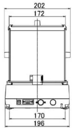
1.1 Dimensions
Models d = 0.001g:
text_image
202 172 170 196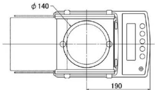
text_image
φ 140 190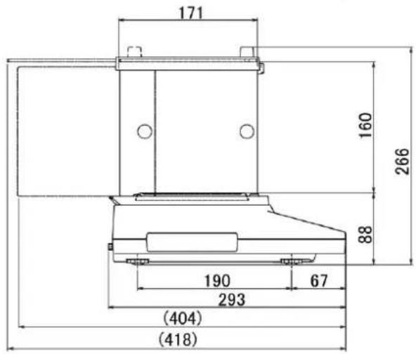
text_image
171 160 266 88 190 67 293 (404) (418)Models d = 0.01g / 0.1 g:
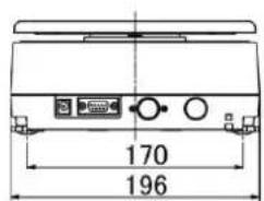
text_image
170 196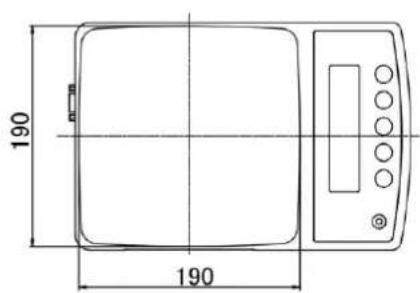
text_image
190 190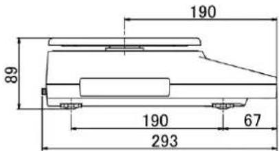
text_image
190 89 190 67 2932 Appliance overview
Models d = 0.001g:
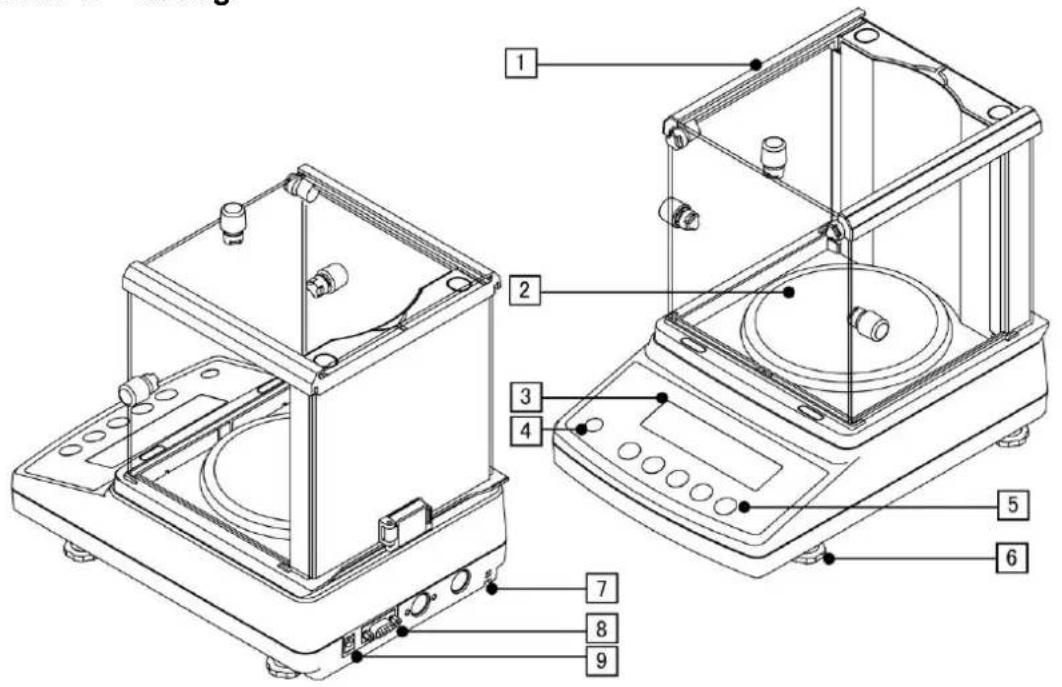
text_image
Technical diagram of an experimental balance with numbered parts for identificationModels d = 0.01g / 0.1 g:
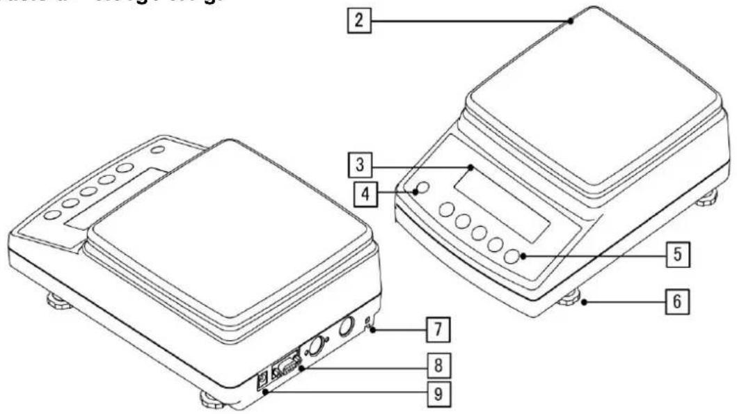
text_image
Technical diagram of a digital balance or analog device with numbered components labeled for identification.Pos. Designation
1 Windshield
2 Weighing pan
3 Display
4 Bubble level
5 Operator keys
Pos. Designation
6 Footscrews
7 Fastening point for anti-theft protection
8 Interface RS232
9 Terminal power supply unit
2.1 Keyboard overview
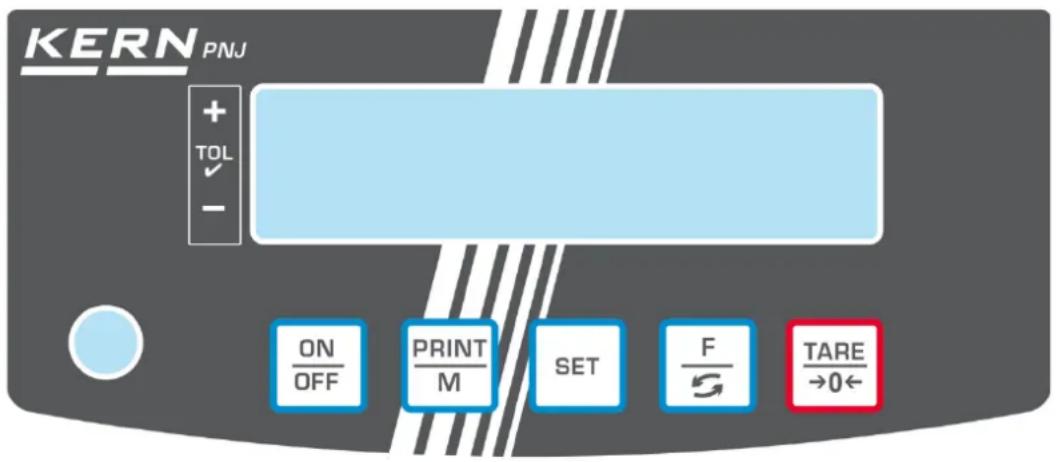
text_image
KERN PNJ + TOL - ON OFF PRINT M SET F S TARE →0←| Button | Function |
 | ➢ Turn on/off |
 | ➢ Transfer weighing data via interface➢ Exit menu / back to weighing mode. |
 | ➢ Save settings/back to weighing mode |
 | ➢ Switch-over weighing unit➢ Menu access (longer pressing of the button)➢ Scroll forward in menu |
 | ➢ Taring➢ Zeroing➢ Change menu settings |
2.2 Overview of display
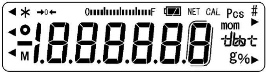
text_image
-18.8.8.8.8 M NET CAL Pcs # mom g%►| Display | Description |
| g | Weighing unit “gram” |
| →0← | Zero indicator |
| NET | Display net weight values |
| ○ | Display of stable values |
| * | The balance is in stand-by modeIlluminated during data transfer |
| Pcs | Application icon for piece counting |
| % | Application icon for percentage determination |
| ◀ | Tolerance mark during check weighing |
| (mom) | Weighing unit „Momme“ |
| M | The balance processor is just processing a function. |
| CAL | Illuminates and flashes during an adjustment process |
| ∫ | Brackets for identifying non verified digits(only verified models) |
| OmmultumF | Capacity displayThe bar graph display moves from the left to the right and proceeds equally to the weight loaded onto the weighing balance. Its full width is reached at maximum load. This is an analogue display of the current allocation of the weighing area. |
| Units fielddtat | [ct] (ct) Carat |
| [oz] (oz) Ounze | |
| [lb] (lb) Pound | |
| [oz t̃ (ozt) Feinunze | |
| [dwt] (dwt) Penny weight | |
| [tl] (tl) Tael (Hong Kong) | |
| [tl ▶ upper right] (tl ▶ upper right) Tael (Singapore,Malaysia) | |
| [tl ▶ [ lower right ] (tl ▶ lower right) Tael (Taiwan) | |
| [to] (to) Tola | |
| [gr ▶ lower right] grain |
3 Basic instructions
3.1 Intended use
The balance you purchased is intended to determine the weighing value of material to be weighed. It is intended to be used as a “non-automatic balance”, i.e. the material to be weighed is manually and carefully placed in the centre of the weighing pan. As soon as a stable weighing value is reached the weighing value can be read.
3.2 Improper Use
- Our balances are non-automatic balances and not provided for use in dynamic weighing processes. However, the balances can also be used for dynamic weighing processes after verifying their individual operative range, and here especially the accuracy requirements of the application.
- Do not leave permanent load on the weighing plate. This may damage the measuring system.
- Impacts and overloading exceeding the stated maximum load (max) of the balance, minus a possibly existing tare load, must be strictly avoided. Balance may be damage by this.
- Never operate the balance in explosive environment. The serial version is not explosion protected.
- The structure of the balance may not be modified. This may lead to incorrect weighing results, safety-related faults and destruction of the balance.
- The balance may only be used according to the described conditions. Other areas of use must be released by KERN in writing.
3.3 Warranty
Warranty claims shall be voided in case
- Our conditions in the operation manual are ignored
- The appliance is used outside the described uses
- The appliance is modified or opened
- Mechanical damage and damage caused by media, liquids, natural wear and tear
- The appliance is improperly set up or incorrectly electrically connected
- The measuring system is overloaded
3.4 Monitoring of Test Resources
In the framework of quality assurance the measuring-related properties of the balance and, if applicable, the testing weight, must be checked regularly. The responsible user must define a suitable interval as well as type and scope of this test. Information is available on KERN's home page (www.kern-sohn.com) with regard to the monitoring of balance test substances and the test weights required for this. In KERN's accredited DKD calibration laboratory test weights and balances may be calibrated (return to the national standard) fast and at moderate cost.
4 Basic Safety Precautions
4.1 Pay attention to the instructions in the Operation Manual

Carefully read this operation manual before setup and commissioning, even if you are already familiar with KERN balances.
4.2 Personnel training
The appliance may only be operated and maintained by trained personnel.
5 Transport and storage
5.1 Testing upon acceptance
When receiving the appliance, please check packaging immediately, and the appliance itself when unpacking for possible visible damage.
5.2 Packaging / return transport

Keep all parts of the original packaging for a possibly required return.
⇒ Only use original packaging for returning.
→ Prior to dispatch disconnect all cables and remove loose/mobile parts.
→ Reattach possibly supplied transport securing devices.
→ Secure all parts such as the glass wind screen, the weighing pan, power unit etc. against shifting and damage.
6 Unpacking, Setup and Commissioning
6.1 Installation Site, Location of Use
The balances are designed in a way that reliable weighing results are achieved in common conditions of use.
You will work accurately and fast, if you select the right location for your balance.
On the installation site observe the following:
- Place the balance on a firm, level surface.
- Avoid extreme heat as well as temperature fluctuation caused by installing next to a radiator or in the direct sunlight.
- Protect the balance against direct draughts due to open windows and doors.
- Avoid jarring during weighing.
- Protect the balance against high humidity, vapours and dust.
- Do not expose the device to extreme dampness for longer periods of time. Non-permitted condensation (condensation of air humidity on the appliance) may occur if a cold appliance is taken to a considerably warmer environment. In this case, acclimatize the disconnected appliance for ca. 2 hours at room temperature.
- Avoid static charge of goods to be weighed or weighing container.
- Do not operate in areas with hazard of explosive material or in potentially explosive atmospheres due to materials such as gasses, steams, mists or dusts.
- Keep away chemicals (such as liquids or gasses), which could attack and damage the balance inside or from outside.
- In the event of the occurrence of electromagnetic fields, static charges (e.g., when weighing / counting plastic parts) and unstable power supply, large display deviations (incorrect weighing results, as well as damage to the scale) are possible. Change location or remove source of interference.
6.1.1 Scope of delivery / serial accessories:
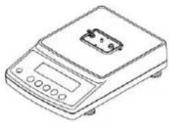
natural_image
Line drawing of a digital kitchen scale with control panel and display (no text or symbols)Balance
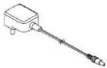
Net adapter and plug set
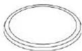
Round weighing pan (models d = 0.001g)

natural_image
Simple line drawing of a square frame with rounded corners (no text or symbols)Angular weighing pan (models d = 0.01g / 0.1 g)
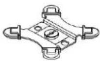
Carrier for round weighing pan (models d = 0.001g)
natural_image
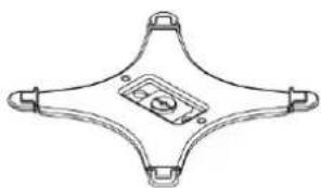
Pure technical line drawing of a symmetrical mechanical component with mounting holes (no text or symbols)Carrier for angular weighing pan (models d = 0.01g / 0.1 g)
natural_image
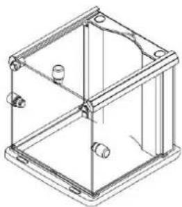
Isometric line drawing of a 3D mechanical housing or enclosure with mounting holes and internal components (no text or symbols)Windshield (models d = 0.001g) Assembly see chap. 6.2

Operating instructions
6.2 Assemble windshield (only models d = 0.001g)
Parts overview:
| Quantity | Quantity | ||
Guide frame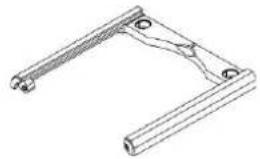 | 1 | Front plate (with 3 bore holes)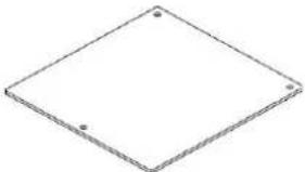 | 1 |
Rear wall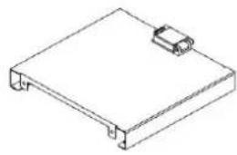 | 1 | Inner plate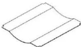 | 1 |
Handle | 3 | ||
Side wall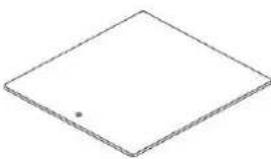 | 3 | Fastening screw “Handle”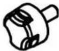 | 5 |
Base frame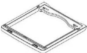 | 1 | Cover | 2 |
Front cap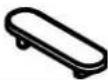 | 2 | ||
Support inner plate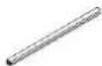 | 2 | M4 screws | 4 |
U-Bolt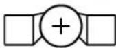 | 1 | ||
Assembly:
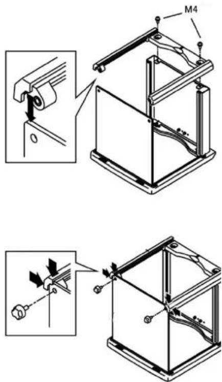
1 → Loosen locking system at the back panel
2 → Fix the back panel on the ground frame with two screws (M4)
3 Assemble the supports for the inner plate acc. to fig.
4
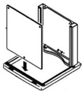
Fasten the front plate.
natural_image
Isometric line drawing of a mechanical assembly with a rectangular frame and base plate (no text or symbols)Make sure that the fastening point is placed at the frame in the bore hole of the front plate.
5
☐ Secure the front plate with the guide frame temporarily against falling out.
text_image
Technical diagram showing mechanical assembly with labeled components and close-up views of a bracket structure6
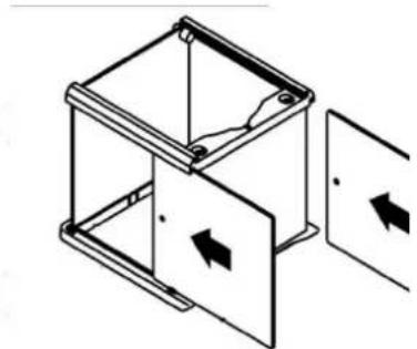
→ Push the side panels from the rear to the front into the guide frame. Make sure that the bore holes point towards the front plate.
natural_image
Isometric line drawing of a 3D cube with internal components and directional arrows, no text or symbols present7
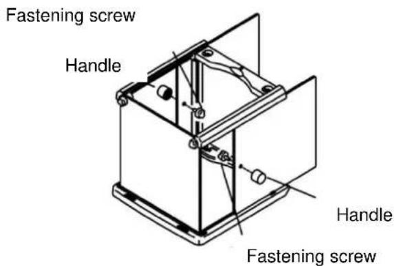
⇒ Fix the handles with the fastening screws.
text_image
Fastening screw Handle Handle Fastening screw8
⇒ Fix the guide frame with two screws (M4).
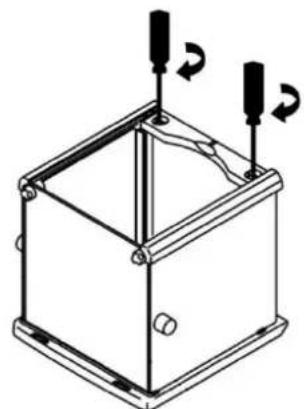
natural_image
Isometric line drawing of a mechanical housing with mounting holes and internal components (no text or symbols)9
→ Attach the covers and the front caps
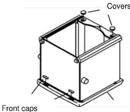
text_image
Covers Front caps10
→ Install inner plate. For this purpose push the plate through the two supports.
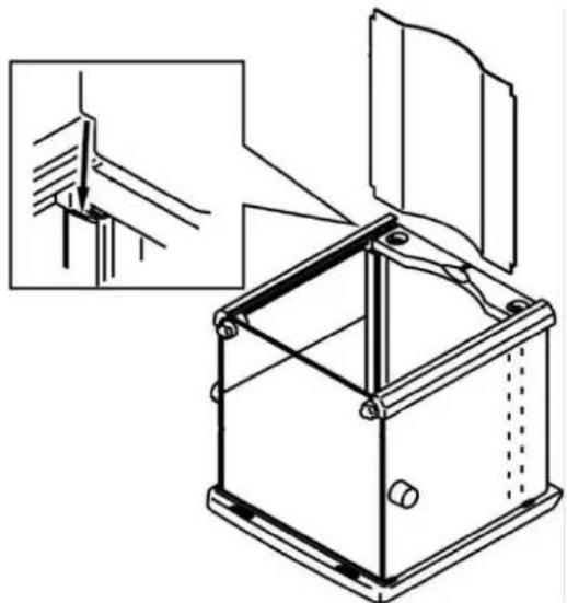
natural_image
Technical line drawing of a mechanical assembly with an inset showing a close-up of a component detail (no text or symbols present)11
Attach the upper glass pane and fix the handles with the fastening screws.
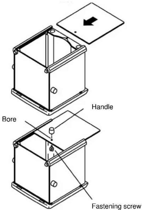
text_image
Bore Handle Fastening screw12
Screw the U-bolt on the underside of the draft shield into the opening provided. The U-bolt is used to dissipate electrostatic charges when touching the draft shield.
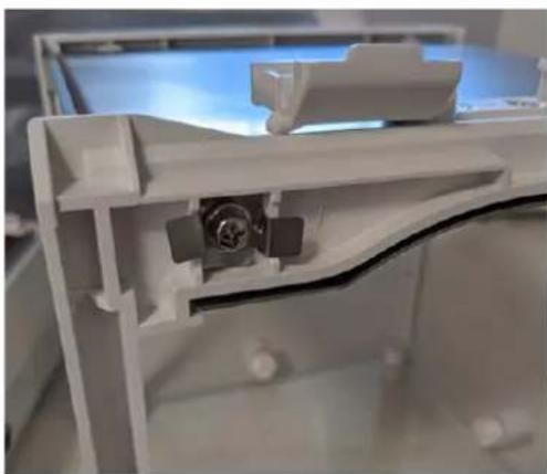
natural_image
Close-up of a white plastic mechanical component with internal components and mounting holes (no visible text or symbols)6.3 Assembly, placing and levelling
The right place is decisive for the accuracy of the weighing results of high-resolution precision balances (see chap. 6.1).
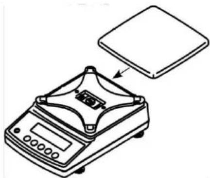
Place the weighing pan carrier acc. to fig. and fix it carefully e.g. with a coin.
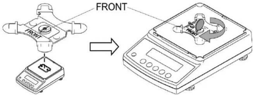
text_image
FRONT FRONT→ Place weighing pan

natural_image
Line drawing of a digital laboratory balance scale with a circular dial indicator (no text or symbols)Models d = 0.001g
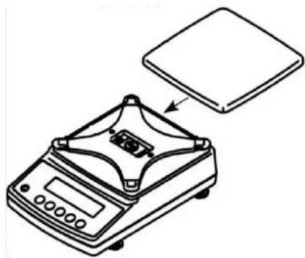
natural_image
Line drawing of a digital balance scale with an open lid and control panel (no text or symbols)Models d = 0.01g / 0.1 g
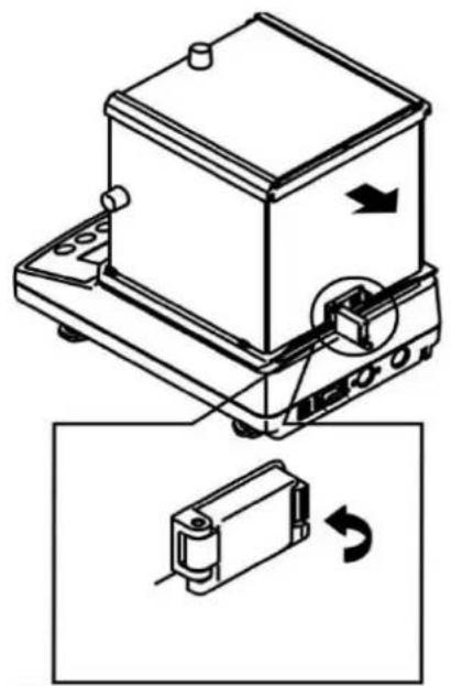
→ Install windshield (only models d = 0.001g). Make sure that the locking system at the back panel is released.
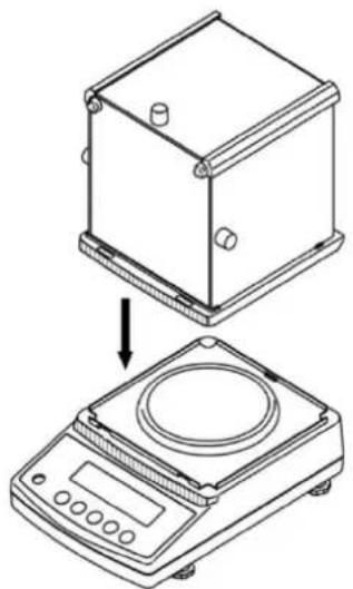
natural_image
Line drawing of a mechanical setup with a cube and digital scale, showing a downward trend from top to bottom (no text or symbols)→ Place the windshield carefully on the balance and align.
→ For safeguarding close the locking system at the back panel.
natural_image
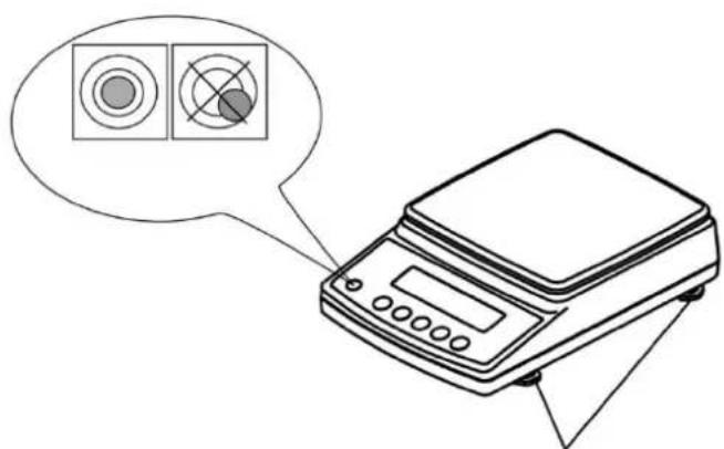
Technical line drawing of a mechanical device with two views: top shows internal components, bottom shows a separate view of a rectangular component (no text or symbols)→ Level balance with foot screws until the air bubble of the water balance is in the prescribed circle.
natural_image
Line drawing of a digital balance scale with two circular gauges and a pointer, no text or symbols present.Footscrews
→ Check levelling regularly
6.4 Mains connection

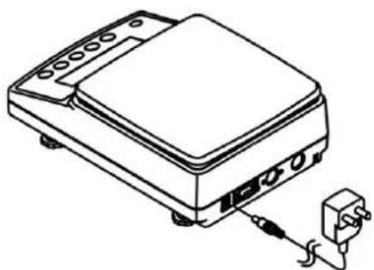
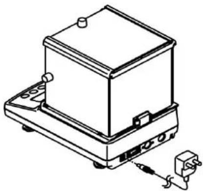
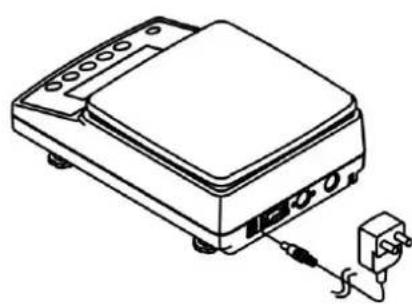
Select a country-specific net plug and mount it on the mains adapter.

Check, whether the voltage acceptance on the scales is set correctly. Do not connect the scales to the power grid unless the information on the instrument (sticker) matches the local mains voltage.
Only use KERN original mains adapter. Using other makes requires consent by KERN.

Important:
Does the rating match the standard local mains current?
Do not connect if mains voltages are different!
If matching, connect the scales.
natural_image
Line drawing of a rectangular electronic device with a power outlet and cable (no text or symbols)Models d = 0.001g
natural_image
Line drawing of a portable electronic device with attached plug and cable (no text or symbols)Models d = 0.01g / 0.1 g
As soon as the balance is supplied with energy, the indicator [ *]s displayed.

text_image
*In order to obtain exact results with the electronic balances, your balance must have reached the operating temperature (see warming up time chap. 1). During this warming up time the balance must be connected to the power supply (mains, accumulator or battery).
The accuracy of the balance depends on the local acceleration of gravity. Strictly observe hints in chapter Adjustment.
6.5 Initial Commissioning
6.5.1 Models PNJ
text_image
*
As soon as the balance is supplied with energy, the indicator [Ms displayed.
To switch on press the ON/OFF button.
All symbols of the display light up shortly.
The balance will carry out a self-test
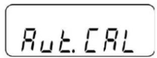
The motor noise of the loading system for the internal adjustment weight can be heard. When „Aut.Cal“ will be displayed the internal adjustment is carried out (see chap. 6.7.1).
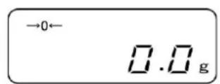
As soon as the weight display appears, the balance is ready for weighing.
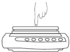
natural_image
Line drawing of a hand pressing down on a tiered appliance (no text or symbols)Check the reaction of the weight display via finger pressure.
6.5.2 Models PNS
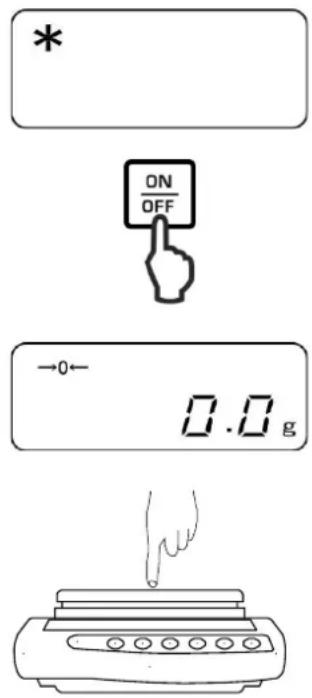
text_image
* ON OFF →0← 0.0 gAs soon as the balance is supplied with energy, the indicator [Ks displayed.
To switch on press the ON/OFF button.
All symbols of the display light up shortly.
The balance is ready for weighing when the weight display appears.
Check the reaction of the weight display via finger pressure.
6.6 Connection of peripheral devices
Before connecting or disconnecting of additional devices (printer, PC) to the data interface, always disconnect the balance from the power supply.
With your balance, only use accessories and peripheral devices by KERN, as they are ideally tuned to your balance.
6.7 Adjustment
As the acceleration value due to gravity is not the same at every location on earth, each display unit with connected weighing pan must be coordinated - in compliance with the underlying physical weighing principle - to the existing acceleration due to gravity at its place of location (only if the weighing system has not already been adjusted to the location in the factory). This adjustment process must be carried out for the first commissioning, after each change of location as well as in case of fluctuating environment temperature. To receive accurate measuring values it is also recommended to adjust the display unit periodically in weighing operation.
i
- Observe stable environmental conditions. Stabilisation requires a certain warm-up time.
- Ensure that there are no objects on the weighing pan.
- When the PRINT-key is pressed during the adjusting procedure, [STOP] will be displayed and adjustment interrupted. The balance returns to weighing mode.
- At the models with internal adjustment weight (KERN PNJ) the adjustment with external weight is not possible.
- The following error messages may be displayed during adjustment.
1-Err Wrong adjustment weight (>80% max)
2-Err Divergence last external adjustment > 1%
3-Err Weighing pan loaded
4-Err Divergence from last internal adjustment > 1%
A-Err Internal adjustment automatics defective
Err 710 Instable environmental conditions
6.7.1 Adjustment with internal weight (only models PNJ)
The internal adjustment weight is available at all times for starting adjustment via keyboard stroke.

flowchart
graph TD
    A["Input: F/S"] --> B["RutCAL"]
    C["TARE →0←"] --> D["+"]
    E["CH.0"] --> F["↓"]
    G["CH.F.S"] --> H["↓"]
    I["bu5y"] --> J["↓"]
    K["End"] --> L["↓"]
    M["0.000g"] --> N["Output"]
Press the F-key and keep pressed until „Aut.CAL“ is displayed.
With pressed TARE key, press the F-key, then release both keys at the same time.
The motor noise of the loading system for the internal adjustment weight can be heard, the internal adjustment is started.
After successful adjustment the balance automatically returns to weighing mode.
In case of an adjustment error (e.g. objects on the weighing pan) the display will show an error message, repeat adjustment.
The adjustment protocol output is started upon connection to an optional printer and activated GLP function (see chap. 11.2.1).
6.7.2 Adjustment with external weight (only models PNS)
Carry out adjustment as near as possible to the balance's maximum weight (recommended adjustment weight see chap. 1).
Info about adjustment weights can be found on the Internet at:
http://www.kern-sohn.com
flowchart
graph TD
    A["0.000g"] --> B["600.000g"]
    B --> C["buy"]
    C --> D["on F.S."]
    D --> E["TARE →0←"]
    E --> F["CAL"]
    F --> G["F"]
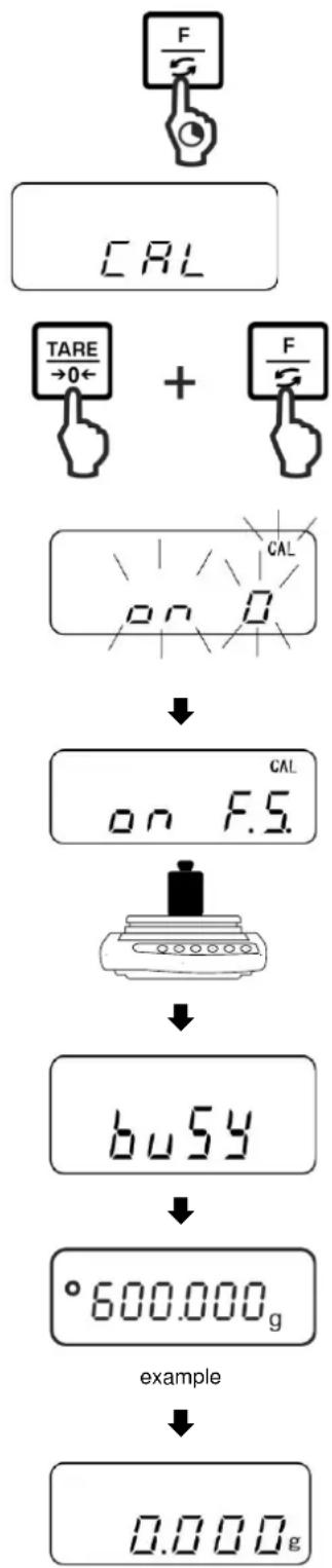
Press the F-key and keep pressed until „CAL“ is displayed.
With pressed TARE key, press the F-key, then release both keys at the same time.
Ensure that there are no objects on the weighing pan.
With display „on FS“ place the required adjustment weight carefully in the center of the weighing pan.
The adjustment process is started.
After successful adjustment the balance automatically returns to weighing mode.
In case of an adjustment error (e.g. objects on the weighing pan) the display will show an error message, repeat adjustment.
Take away adjustment weight.
6.8 Verification
General hints
According to EU directive 2014/31EU balances must be officially verified if they are used as follows (legally controlled area):
a) For commercial transactions if the price of goods is determined by weighing.
b) For the production of medicines in pharmacies as well as for analyses in the medical and pharmaceutical laboratory.
c) For official purposes
d) For manufacturing final packages
In cases of doubt, please contact your local trade in standard.
Verification notes:
An EU type approval exists for balances described in their technical data as verifiable. If a balance is used where obligation to verify exists as described above, it must be verified and re-verified at regular intervals.
Re-verification of a balance is carried out according to the respective national regulations. The validity for verification of balances in Germany is e.g. 2 years. The legal regulation of the country where the balance is used must be observed!
Verification of the balance is invalid without the seal.
The seal marks attached on balances with type approval point out that the balance may only be opened and serviced by trained and authorised specialist staff. If the seal mark is destroyed, verification looses its validity. Please observe all national laws and legal regulations. In Germany a reverification will be necessary.
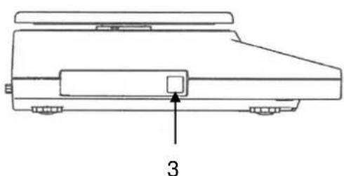
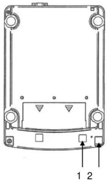
Position seals and verification switch
Prior to verification, the verification switch must be moved into the verification position. In this position the display shows a bracket around the last display point. After verification the balance is sealed at the indicated positions.
natural_image
Technical line drawing of a device rear panel with labeled components (no text or symbols beyond labels)Models d = 0.01g / 0.1 g
Models d = 0.001g
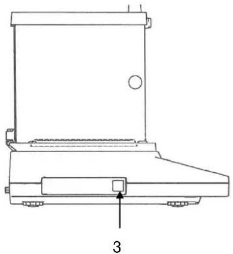
natural_image
Technical line drawing of a mechanical device with labeled component '3' (no text or symbols beyond label)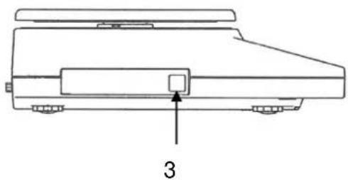
natural_image
Technical line drawing of a mechanical component with labeled part '3' (no text or symbols beyond label)1 Switch cover / Position verification switch
2 Self-destroying seal mark
3 Metrology mark [M]
7 Basic Operation
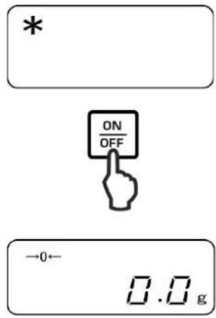
7.1 Start-up
text_image
* ON OFF →0← 0.0 gAs soon as the balance is supplied with energy, the indicator [K]s displayed.
To switch on press the ON/OFF button.
All symbols of the display light up shortly.
The balance is ready for weighing when the weight display appears.
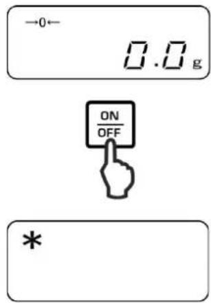
7.2 Switch into stand-by mode
text_image
-0← 0.0 g ON OFF *Press ON/OFF button, the display disappears
The indicator [ *will be shown.
i
In stand-by mode the balance is ready for operation immediately after switching-on without warm-up time.
To switch off the balance completely, separate it from the mains.
The balance starts in the mode, in which it has been switched off.
7.3 Zeroing
In order to obtain optimal weighing results, reset to zero the balance before weighing.
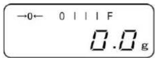
Unload the balance.
Press the TARE key.
Wait until the zero display and the indicator a will appear.
i During the zeroing procedure a flashing „M“ will be displayed.
7.4 Simple weighing
text_image
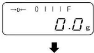
-0← 0 | | | F 0.0 gPlace goods to be weighed on balance.
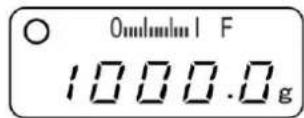
Wait for stability display
Read weighing result.
i
➢ Capacity display [ ] 0mm1mm1 F
At active capacity display (see chap. 0 „1.b.G.1“) the bar graph moves from the left to the right and proceeds equally to the weight loaded onto the weighing balance. Its full width is reached at maximum load. This is an analogue display of the current allocation of the weighing area.
▶ Overload warning
Overloading exceeding the stated maximum load (max) of the device, minus a possibly existing tare load, must be strictly avoided. This could damage the instrument.
Exceeding maximum loads is indicated by the display of "o-Err", and an audio sound. Unload weighing system or reduce preload.
7.5 Unity change
By repeated pressing of the F-key the weight value can be switched over by factory into the following units.

In model PNJ 12000-1M the unit of carat ("ct") is unavailable.
Changes can be set in the menu (function 81.S.u - 85.S.u).
Function Description
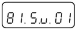
81.S.u Adjustment of the first weighing unit where the balance has to display the weighing result.
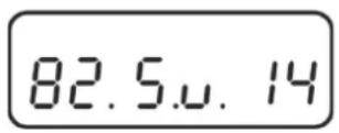
82.S.u Adjustment of the second weighing unit where the balance has to display the weighing result.
83.S.u Adjustment of the third weighing unit where the balance has to display the weighing result.
84.S.u Adjustment of the forth weighing unit where the balance has to display the weighing result.
85.S.u Adjustment of the fifth weighing unit where the balance has to display the weighing result.
Call up menu:
Press the F-key and keep pressed until „Func“ is displayed.

When releasing the button, the first function „1.b.G., is displayed with the current setting.
text_image
TARE →0← 82.5.u.16Call function:
Press repeatedly the F-button until „81.Su.“ with the current setting is displayed.
Use the F-key to select the weighing unit to be changed e.g. „82.s.u“.
Change settings:
e.g. function „82.s.u“ [ct] in [lb]:
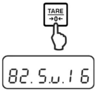
In order to change the current setting of [Karat] „82.Su.14“ e.g. in [Pound] press the TARE-key repeatedly until „82.Su.16“ will be displayed.
For available settings see chap. 0
To change other units, select the next function („83.s.u“ – „85.s.u „) using the F-key and change as described above.
text_image
SET →0← 0.0 g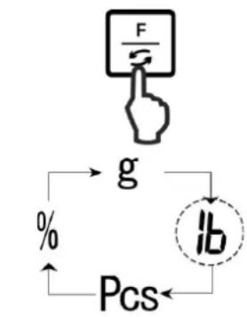
flowchart
graph TD
    A["Hand pressing F"] --> B["g"]
    B --> C["Pcs"]
    C --> D["lb"]
    D --> B
    style A fill:#f9f,stroke:#333
    style B fill:#ccf,stroke:#333
    style C fill:#cfc,stroke:#333
    style D fill:#fcc,stroke:#333
Save / back to weighing mode:
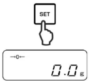
Confirm settings with SET-key. The balance returns to weighing mode.
Unit change:
By repeated pressing of the F-key the weight value can be switched over now into the following units.
Navigation in menu, see chap.
➢ After that no more switch-over in another unit will be possible with setting „00“.
Setting „00“ is not available with function „81.S.u“.
For balances with type approval not all weighing units are available.
7.6 Weighing with tare
7.6.1 Taring
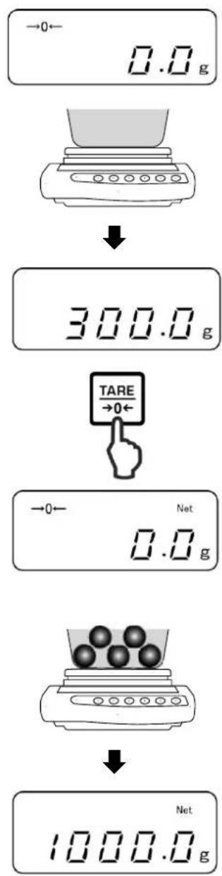
The dead weight of any weighing container may be tared away by pressing a button, so that the following weighing procedures show the net weight of the goods to be weighed.
flowchart
graph TD
    A["→0← 0.0 g"] --> B["↓"]
    B --> C["300.0 g"]
    C --> D["TARE →0←"]
    D --> E["→0← Net 0.0 g"]
    E --> F["↓"]
    F --> G["Net 1000.0 g"]
Set balance to zero
Deposit empty weighing container. The result is displayed.
Wait for stability display, then press the TARE button The weight of the container is now internally saved. The zero display and „Net“ will appear. „Net“ signals that all shown weight values are net values.
Weigh the material, the net weight will be indicated.
i
- When the balance is unloaded the saved taring value is displayed with negative sign.
- To delete the stored tare value, remove load from weighing pan and press the TARE button.
7.6.2 Multiple tare
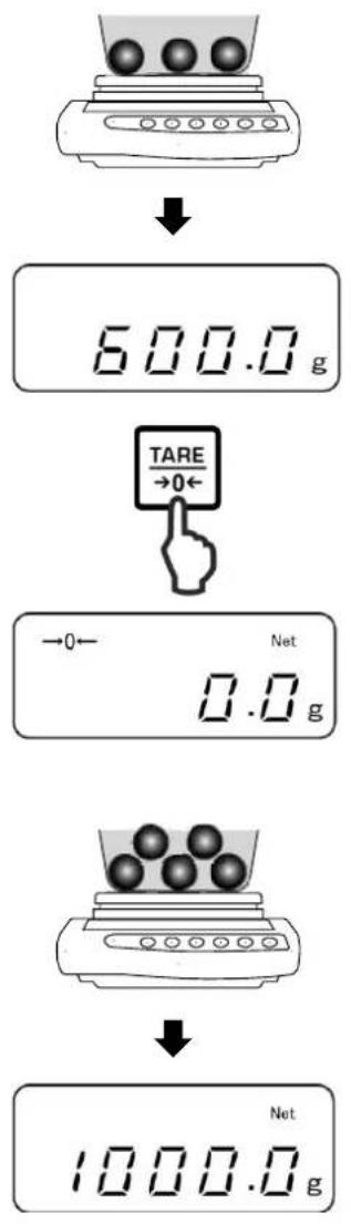
The taring process can be repeated any number of times, e.g. when adding several components for a mixture (adding). The limit is reached when the taring range capacity is full.
flowchart
graph TD
    A["Start: Temperature Scale with Sensor"] --> B["Step 1: 600.0 g"]
    B --> C["Step 2: TARE → 0 ←"]
    C --> D["Step 3: Net Temperature Scale with Sensor"]
    D --> E["Step 4: Net Temperature Scale with Sensor"]
    E --> F["End: 1000.0 g"]
Place first good to be weighed on balance. The result is displayed.
Wait for stability display, then press the TARE button The zero display and „Net“ will appear.
Weigh-in the second weighing material. The weight of the second weighing good is displayed.
For more weighing material repeat the two last steps.
8 Menu
8.1 Menu [function]
8.1.1 Navigation in the menu
1. | Access to menu
In weighing mode keep the F-key pressed down until [FWnm] appears on the display. Release button. The first menu item showing the current setting will be displayed.
2. Select menu items
⇒ Press the F-key to select the individual menu items showing the current settings one by one.
3. Change settings
→ Press the TARE-key to change the setting of a selected menu item. Each time the TARE-key is pressed the next setting will be displayed. As soon as the desired setting appears on the display you can select the next menu item with the F-key (see step 3) or exit the menu (see step 4 / 5)
4. How to save settings and to exit the menu
⇒ Press the S-key; balance will return to weighing mode.
or
⇒ Press the F-key repeatedly until the weighing balance returns to weighing mode.
All changes will be saved.
5. Cancel
⇒ Press the PRINT-key briefly; balance will return to weighing mode. Changes will not be saved.

text_image
Func 1.6.0.1 2.SEL 0 3.8.0.1 2.SEL 0 TARE →0← 2.SEL 1 SET →0← 0.0 g PRINT M →0← 0.0 g8.1.2 Menu overview
Factory settings are marked by *.
| Menu item |  |  | Description | |
| 1 Capacity display | 1.b.G. | 1 | Hide capacity display | |
| * 2 | Display capacity display | |||
| 2 Tolerance weighing see chap. 9.3 | 2.SEL | * 0 | Disable tolerance weighing | |
| 1 | Enable tolerance weighing | Settings see chap. 9.3.1 | ||
| 3 Automatic zero point correction see chap. 10.1 | 3.A.0 | 0 | Automatic zero tracking off | |
| * 1 | Automatic zero tracking on | |||
| 4 Automatic shutdown for battery operation | 4.A.P. | 0 | Not documented(function is only available in rechargeable battery operation) | |
| * 1 | ||||
| 5 Display speed see chap. 0 | 5.rE. | 0 | Setting for dosage | |
| 1 | Very quiet and stable environment.The balance works very fast but is sensitive to outside influences. | |||
| 2 | ||||
| * 3 | Normal conditions. Weighing balance working at medium speed. | |||
| 4 | ||||
| 5 | Busy environment. The balance works slower, but is insensitive to outside influences | |||
| 6 Adapt standstill control see chap. 0 | 6.S.d. | 1 | The balance works very fast | |
| * 2 | The balance works at medium speed | |||
| 3 | ||||
| 4 | The balance works with the utmost precision | |||
| 7 RS232C-interface | 7. I.F. | 0 | Deactivated | |
| 1 | 6-digit data format | |||
| 2 | 7-digit data format | |||
| *3 | 6-digit data format (ASCII) | |||
| 4 | 7-digit data format (ASCII) | |||
| (In models PNJ 1 and 2 they are unavailable) | ||||
| 7.1 Output condition only during setting [7.I.F. 1] or [7.I.F. 2] | 71.o.c | 0 | No data output | |
| 1 | Continuous data output | |||
| 2 | Continuous data output stable weighing values | |||
| *3 | Output of stable and instable weighing values after pressing PRINT key | |||
| 4 | Output with stable weighing value after previous relief of balance | |||
| 5 | One output with stable weighing value. No output with stable weighing values. Renewed output after stabilization | |||
| 6 | One output with stable weighing value. Continuous output with instable weighing values. | |||
| *7 | Output of stable weighing values after pressing PRINT key | |||
| 7.2 Baud rate | 72.b.L. | *1 | 1200 bps | |
| 2 | 2400 bps | |||
| 3 | 4800 bps | |||
| 4 | 9600 bps | |||
| 5 | 19200 bps | |||
| 7.3 Parity only during setting [7.I.F. 2] | 73.PA. | *0 | No parity bit | |
| 1 | Odd parity | |||
| 2 | Even parity | |||
| 8 Change weighing unitsee chap. 7.5Not available in verifiedweighing balances[gr] In model PNS12000-1 it isunavailable. | 81.S.u.↓85. S.u. | *1 01 | [g] | |
| *2 14 | [ct] | |||
| 15 | [oz] | |||
| 16 | [lb] | |||
| 17 | [ozt] | |||
| 18 | [dwt] | |||
| 19 | [gr] | |||
| 1A | [tl_HK] | |||
| 1B | [tl_Singap. Malays] | |||
| 1C | [tl_Tw] | |||
| 1D | [mom] | |||
| 1E | [tol] | |||
| *3 20 | [Pcs] | |||
| *4 1F | [%] | |||
| 00 | After that no more switch-over in anotherunit will be possible.. | |||
| 10 GLP-compliant print(only models PNJ),see chap.11.2.1 | 0. GLP | 0 | No | |
| * 1 | Yes | |||
| 11 Data output of verifiedmodels(settings only availablein a non verified status) | A. PrF. | 1 | Data output disabled | |
| 2 | Data outputenabled | Sample protocol:+0075.55 G S | ||
| * 3 | Data outputenabled.Non verified valueseparated by „/“ | Sample protocol:+0075.5/5 G S | ||
| 12 Set the date formatsee chap. 10.6 | b.dAt. | 1 | Display in year-month-day | |
| 2 | Display in month-day-year | |||
| * 3 | Display in day-month-year | |||
| 13 Edit date / time onprotocolsee chap. 11.2.2 | C. t.o. | 0 | Edit weighing value without date / time | |
| * 1 | Edit weighing value with time | |||
| 2 | Edit weighing value with date + time | |||
| 14 Adjust back lighting ofthe display | d. b.L. | 0 | No | |
| * 1 | Yes | |||
| 15 Switch-off the backlighting of the displayautomatically,see chap. 10.4 | E. A.b | 0 | No | |
| * 1 | Yes | |||
8.2 Menu [Function2]
8.2.1 Navigation in the menu
Access to menu
In weighing mode press the F-key and the TARE-key at the same time and keep it pressed until „Func2“ will be displayed.
⇒ When released, the first menu item „1.CrC. 0.“ is displayed.

Select the menu items, change and take over settings see chap. 8.1.1
8.2.2 Menu overview
Default setting is marked by *.
Menu item
| Display software statussee chap. 10.3 |
-
CRC.
-
S.C.T.
| Setting date / time, see chap. 10.5 |
- D., SET
Description
| * 0 | no |
| 1 | yes |
| * 0 | Not documented |
| 1 | |
| * 0 | no |
| 1 | yes |
9 Applications
9.1 Parts counting
Before the balance can count parts, it must know the average part weight (i.e. reference). Proceed by putting on a certain number of the parts to be counted. The balance determines the total weight and divides it by the number of parts, the so-called reference quantity. Counting is then carried out on the basis of the calculated average piece weight.
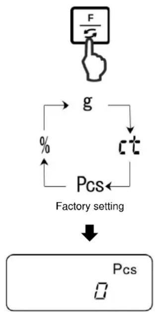
flowchart
graph TD
    A["Hand icon with 'F' inside"] --> B["g"]
    B --> C["%"]
    C --> D["Pcs"]
    D --> E["Factory setting"]
    E --> F["Pcs"]
1. Call application
Press the F-button repeatedly until „Pcs“ is displayed.
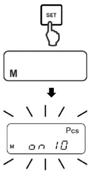
flowchart
graph TD
    A["SET"] --> B["M"]
    B --> C["Pcs"]
    C --> D["M on 10"]
2. Set to zero/taring
Press the TARE-button to set the balance to zero or to tare when using a weighing container.
3. Reference setting
Press SET-key.
Wait until the currently set reference quantity will flash in the display.
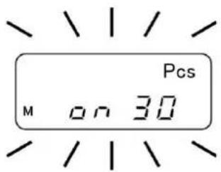
text_image
Pcs M on 304. Change reference quantity
Select the desired reference quantity using the TARE-key, e.g. 30 items. You can choose
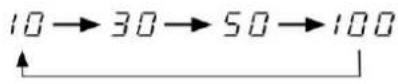
Important:
The higher the reference quantity the higher the counting exactness.
text_image
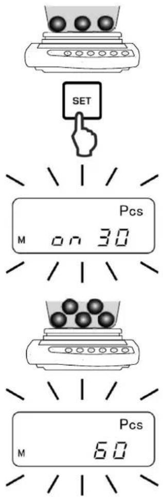
SET Pcs M on 30 Pcs M 605. Weigh-in reference parts
Place as many pieces to add-up as required by the set reference piece number.
Use the SET key to confirm.
6. Reference optimisation
For reference optimisation place again the same quantity of counted pieces.
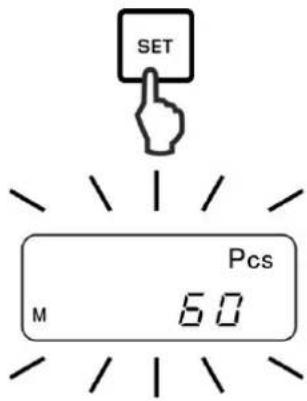
text_image
SET Pcs M 60Use the SET key to confirm.
At every reference optimisation, the reference weight is calculated anew. As the additional pieces increase the base for the calculation, the reference also becomes more exact.
For further reference optimisation place more counted pieces (approx. 1/2 to 1/5 of the counted material). Execution see step 5.

7. How to save the reference
Press the PRINT-key to save the reference whereupon the weighing scale automatically calculates an average weight per part.
Remove reference weight. The balance is now in parts counting mode and counts all units on the weighing pan.

8. Count the items
Place load on pan and read the number of pieces.
Sample protocol (KERN YKB-01N)
+0000125 PC S
9. Printing
The display value will be printed out by connecting an optional printer and pressing the PRINT-key (factory setting).
i
Display Description
ADD The number of pieces placed is too small for a correct reference calculation. Either you accept the error and confirm by pressing the PRINT-key or you add additional items.
L-ERR Piece below minimum weight of piece (see chap. 1 "Technical specifications"):
To interrupt a reference calculation, press the PRINT-key.
The reference weight will remain stored even after the weighing balance was turned off until the reference is reset.
9.2 Percent determination
Percentage calculation facilitates weight display in percent related to a reference weight equivalent to 100 %.

flowchart
graph TD
    A["Hand icon with 'F' inside"] --> B["g"]
    B --> C["Factory setting"]
    C --> D["Pcs"]
    D --> E["%"]
    E --> B
    style A fill:#f9f,stroke:#333
    style B fill:#ccf,stroke:#333
    style C fill:#cfc,stroke:#333
    style D fill:#fcc,stroke:#333
    style E fill:#ffc,stroke:#333
1. Call application
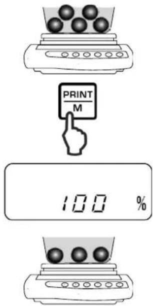
Press the F-button repeatedly until „%“ is displayed.
2. Zeroing/taring
Press the TARE-button to set the balance to zero or to tare when using a weighing container.
3. Reference setting (100 % value)
Press SET-key.
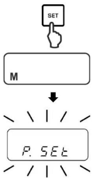
flowchart
graph TD
    A["SET"] --> B["M"]
    B --> C["P. SET"]
Wait until „P. SET“ will be displayed.
text_image
PRINT M 100 %Sample protocol (KERN YKB-01N)
+00033.33 % S
Place the reference weight (= 100 %) and confirm by pressing the PRINT-key.
4. Percent determination
Place goods to be weighed on balance.
The weight of the sample is displayed in percentage in terms of the reference weight.
5. Printing
The display value will be printed out by connecting an optional printer and pressing the PRINT-key (factory setting).
i
Display Description
1 % Minimum load ≤ reference weight < minimum load x 10
0.1 % Minimum load x 10 ≤ reference weight < minimum load x 100
0.01 % Minimum load x 100 ≤ reference weight
L-ERR Reference weight < Minimum weight = underload (minimum load depending on model, see chap. 1 „Technical data“)
The reference weight (100 %) will remain stored even after the weighing balance was turned off until the reference is reset.
9.3 Weighing with tolerance range
Using the application „Weighing with tolerance range“ you can set an upper or lower limit value and thus ensure that the weighed load remains exactly within the set tolerance limits.
Limit value inputs are possible at the functions weighing, parts counting and percentage determination.
There are two different ways to set the tolerance limits:
- By weighing, that is by placing item on weighing balance and saving this value as nominal weight, see chap. 9.3.2
- Numeric input of nominal values via keyboard, see chap. 9.3.3
Display of the results:
The triangular tolerance marker [◀] in the display of the display shows whether the goods to be weighed are within the two tolerance limits. The tolerance mark is only visible when function „2.SEL 1“ is enabled (see chap. 9.3.1).
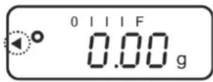
The tolerance mark provides the following information:
1. Menu setting „23.Pi. 2“ / two limit values
Load below specified tolerance
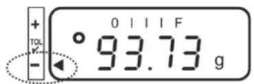
text_image
+ TOL - ° 93.73 g 0 I I I FLoad within specified tolerance
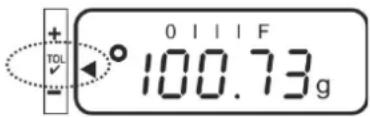
text_image
TOL + - 100.73g 0 I I I FLoad exceeds specified tolerance
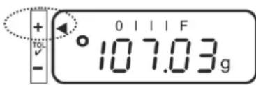
text_image
+ TOL - 0 I I I F 107.03g2. Menu setting „23.Pi. 1“ / one limit value
Weighing good < Target weight
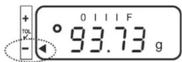
text_image
+ TOL - ° 93.73 g 0 I I I FTarget weight reached
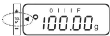
text_image
TOL - 0 I I I F 100.00 gWeighing good > Target weight
No information
9.3.1 Enable function / settings in menu
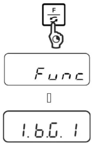
text_image
F Func 1.6.0.1Call up menu:
Press the F-key and keep pressed until „Func“ is displayed.
When releasing the button, the first function „1.b.G., is displayed with the current setting.
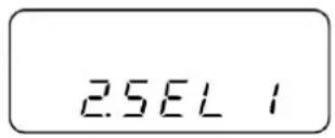
Enable function for tolerance weighing „2.SEL. 1“:
Press the F-key until „2.SEL.“ with the current setting is displayed.
Enable the function using the TARE-key.
text_image
2.5EL 1„2.SEL. 0“ Function deactivated
„2.SEL. 1“ Function activated
text_image
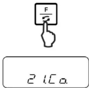
F 2 1 C o.Use the F-key to select the next menu item "21.Co. for setting the display conditions for the tolerance mark.
Use the TARE-key to select the desired setting
„21.Co. 1“ The tolerance mark is displayed with stable and instable weighing values
„21.Co. 2“ The tolerance mark is only displayed with stable weighing values.
Use the F-key to select the next menu item „22.Li. for setting the tolerance range.
22L
Use the TARE-key to select the desired setting
„22.Li. 0“ The tolerance mark is only displayed above zero range (>5 d).
„22.Li. 1“ Tolerance marker is displayed for the whole range.
Use the F-key to select the next menu item "23.Pi. for setting the number of limit points.
23P.
Use the TARE-key to select the desired setting
„23.Pi. 1“ 1- Limiting point (OK/ -)
„23.Pi. 2“ 2- Set the limit point as lower and upper limit (+ / OK / -)
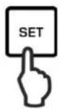
Save / back to weighing mode:
Confirm settings with SET-key. The balance returns into the tolerance weighing mode
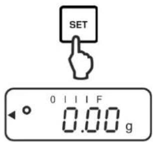
text_image
SET 0 I I I F 0.00 g9.3.2 Tolerance check after setting the limit values by weighing
1.
text_image
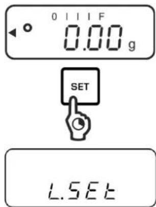
0 I I I F 0.00 g SET L.SETPress the SET-key and keep it pressed until the display for setting the lower limit value „L.SET“ appears. The current setting flashes.
2.
text_image
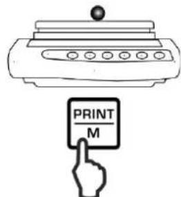
PRINT MPlace the nominal weight (e.g. 95 g) for the lower limit value and confirm with PRINT-key.
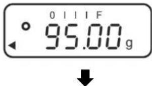
text_image
0 I I I F ° 95.00 gFor menu setting „23.Pi. 1“ the input finishes here. Start tolerance check, see step 4.
For menu setting „23.Pi. 2“ wait until the display „H.SET“ for setting the upper limit value appears. The current setting flashes.
3.
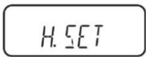
Place the nominal weight (e.g. 105 g) for the upper limit value and confirm with PRINT-key.
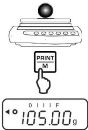
text_image
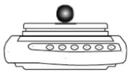
PRINT M 0 1 1 F 105.00 gRemove the nominal weight. From here evaluation takes place whether the goods to be weighed are within the two tolerance limits.
4.
Sample displays:
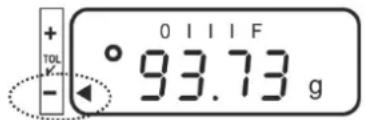
text_image
+ TOL - ° 93.73 g 0 I I I F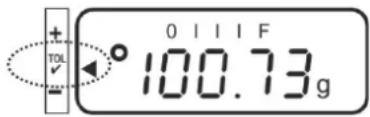
text_image
TOL + - 100.73g 0 I I I F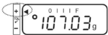
text_image
+ TOL - 0 I I I F 107.03 g5.
Sample protocols (KERN YKB-01N)
+100.73 GGS
Load within specified tolerance
+093.73 GLS
Load below specified tolerance
+107.03 GHS
Load exceeds specified tolerance
Start tolerance check
If necessary, place an empty container on the balance and tare it.
Place goods to be weighed on balance. With the help of the tolerance mark [+] check if the weighed goods are under, inside or over the default tolerance.
Load below specified tolerance
Load within specified tolerance
Load exceeds specified tolerance
Printing
The display value will be printed out by connecting an optional printer and pressing the PRINT-key (factory setting).
| G | Weighing unit “gram” |
| G | Load within specified tolerance |
| S | Stable value |
| L | Load below specified tolerance |
| H | Load exceeds specified tolerance |
9.3.3 Tolerance check after numeric input of the limit values
1.
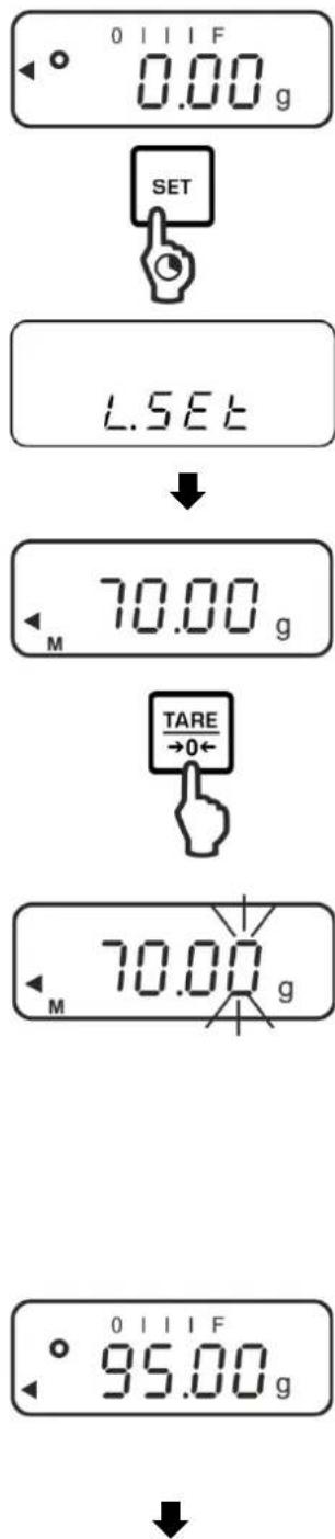
text_image
0 I I I F 0.00 g SET L.SET 70.00 g TARE →0← 70.00 g 0 I I I F 95.00 gPress the SET-key and keep it pressed until the display for setting the lower limit value „L.SET“ appears. The current setting e.g. „70.00 g“ flashes.
2.
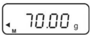
For numeric input of the nominal weight (e.g. 95 g) press the TARE-key for the lower limit value. The last digit flashes.
Numeric input:

text_image
70.00 g M
To change a digit press the TARE-key.
Select digit using the F-key (from the right to the left). The selected digit is flashing.
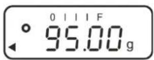

Store entry

For menu setting „23.Pi. 1“ the input finishes here. Start tolerance check, see step 4.
3.
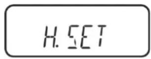
For menu setting „23.Pi. 2“ wait until the display „H.SET“ for setting the upper limit value appears. The current setting flashes.
For numeric input of the nominal weight (e.g. 105 g) press the TARE-key for the upper limit value. The last digit flashes.
Numeric input see step 2.
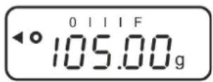

Save input with XX. The balance returns into the tolerance weighing mode
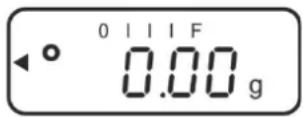
From here evaluation takes place whether the goods to be weighed are within the two tolerance limits.
4.
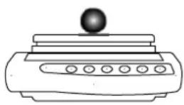
Start tolerance check
If necessary, place an empty container on the balance and tare it.
Place goods to be weighed on balance. With the help of the tolerance mark [→] check if the weighed goods are under, inside or over the default tolerance.
Display example see chap. 9.3.2
5.
Printing
The display value can be printed out by connecting an optional printer and pressing the PRINT-key (factory setting), sample protocols, see chap. 9.3.2
10 General functions
10.1 Zero-tracking
This function is used to tare small variations in weight automatically.
In the event that small quantities are removed or added to the material to be weighed, incorrect weighing results can be displayed due to the “stability compensation”. (e.g. slow flow of liquids from a container placed on the balance, evaporating processes).
When apportioning involves small variations of weight, it is advisable to switch off this function.
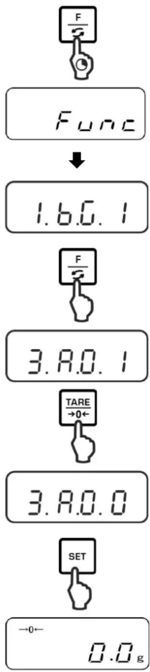
flowchart
graph TD
    A["F"] --> B["Func"]
    B --> C["1.6.0.1"]
    C --> D["F"]
    D --> E["3.8.0.1"]
    E --> F["TARE →0←"]
    F --> G["3.8.0.0"]
    G --> H["SET"]
    H --> I["-0← 0.0 g"]
Call up menu:
Press the F-key and keep pressed until „Func“ is displayed.
When releasing the button, the first function „1.b.G., is displayed with the current setting
Enable/disable zero-tracking function:
Press F-key repeatedly until „3.A0.“ with the current setting is displayed.
Use the TARE-key to select the desired setting.
„3.A0 1“ Function activated
„3.A0 0“ Function deactivated
Save / back to weighing mode:
Confirm setting with SET-key. The balance returns to weighing mode.
10.2 Settings for Stability and Response
Exists the possibility to tune the stability of the display and the degree of reaction of the balance to the requirements of certain applications or the environmental conditions.
Please note that in general slowing down reaction times result in higher stability of the set data handling, while speeding up reaction times have an influence on the stability deterioration.
| Installation site | Menu setting „5.rE. | Menu setting „6.S.d“ |
| Quiet | 1 | 1 |
| 2 | 2 | |
| ↑Busy | 3 | 3 |
| 4 | 4 | |
| 5 |
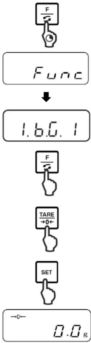
flowchart
graph TD
    A["F"] --> B["Func"]
    B --> C["1.6.0.1"]
    C --> D["TARE →0←"]
    D --> E["SET"]
    E --> F["0.0 g"]
Press the F-key and keep pressed until „Func“ is displayed.
When releasing the button, the first function „1.b.G., is displayed with the current setting.
Press F-key repeatedly until „5.rE.“ or „6S.d“ with the current setting is displayed.
Use the TARE-key to select the desired setting.
Save / back to weighing mode:
Confirm setting with SET-key. The balance returns to weighing mode.
10.3 Show software status
text_image
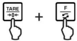
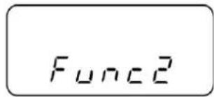
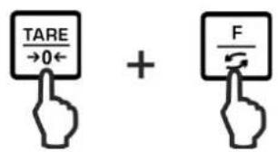
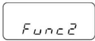
TARE →0← + FPress the F-key and the TARE-key at the same time and keep them pressed until „Func2“ will be displayed.
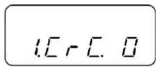
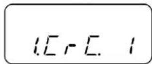
When released, „1.CrC. 0.“ is displayed.
text_image
Func2
text_image
1.C - C. 0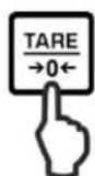
text_image
1.5 - 5. 1
text_image
URA LE

text_image
***
Use the TARE-key to select the setting „1.CrC. 1.“
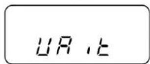
Press F-key. Wait until the software status of the balance is displayed.
Return to weighing mode:
Press the F-key repeatedly.
10.4 Switch-off background illumination of the display automatically
When function is enabled background illumination of display will automatically switch off after 1 minute during which there was no change of load or activity.
flowchart
graph TD
    A["F"] --> B["Func"]
    B --> C["1.6.0.1"]
    C --> D["F"]
    D --> E["E.8.6.0"]
    E --> F["TARE →0←"]
    F --> G["E.8.6.1"]
    G --> H["SET"]
    H --> I["-0← 0.0 g"]
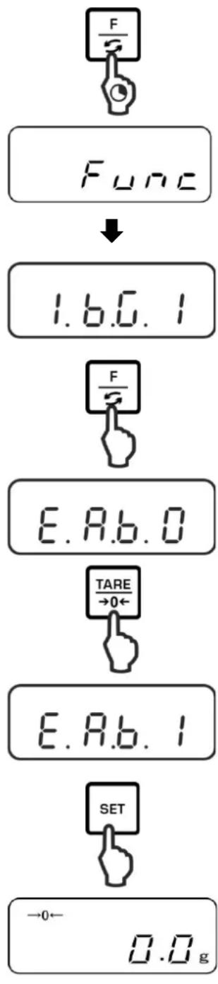
Call up menu:
Press the F-key and keep pressed until „Func“ is displayed.
When releasing the button, the first function „1.b.G., is displayed with the current setting.
Enable/disable auto-backlight function:
Press repeatedly the F-button until „E.A.b.“ appears with the current setting.
Use the TARE-key to select the desired setting.
„E.A.b. 0“ Function deactivated
„E.A.b. 1“ Function activated
Save / back to weighing mode:
Confirm setting with SET-key.
The balance returns to weighing mode.
10.5 Setting date / time
10.5.1 Setting time
text_image
TARE →0← + FPress the F-key and the TARE-key at the same time and keep them pressed until „Func2“ will be displayed.
text_image
Func2When released, „1.CrC. 0.“ is displayed.

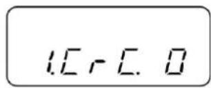
text_image
1.C - C. 0
text_image
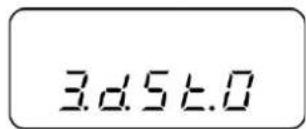
3.05±0Press F-key repeatedly until „3.d.St.0“ is displayed.
text_image
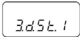
3.056.1Use the TARE-key to select „3.d.St.1“.

text_image
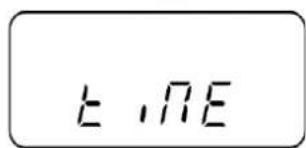
E ,I/EPress F-key. „tiME“ is displayed, followed by the current set time.
13.45.27
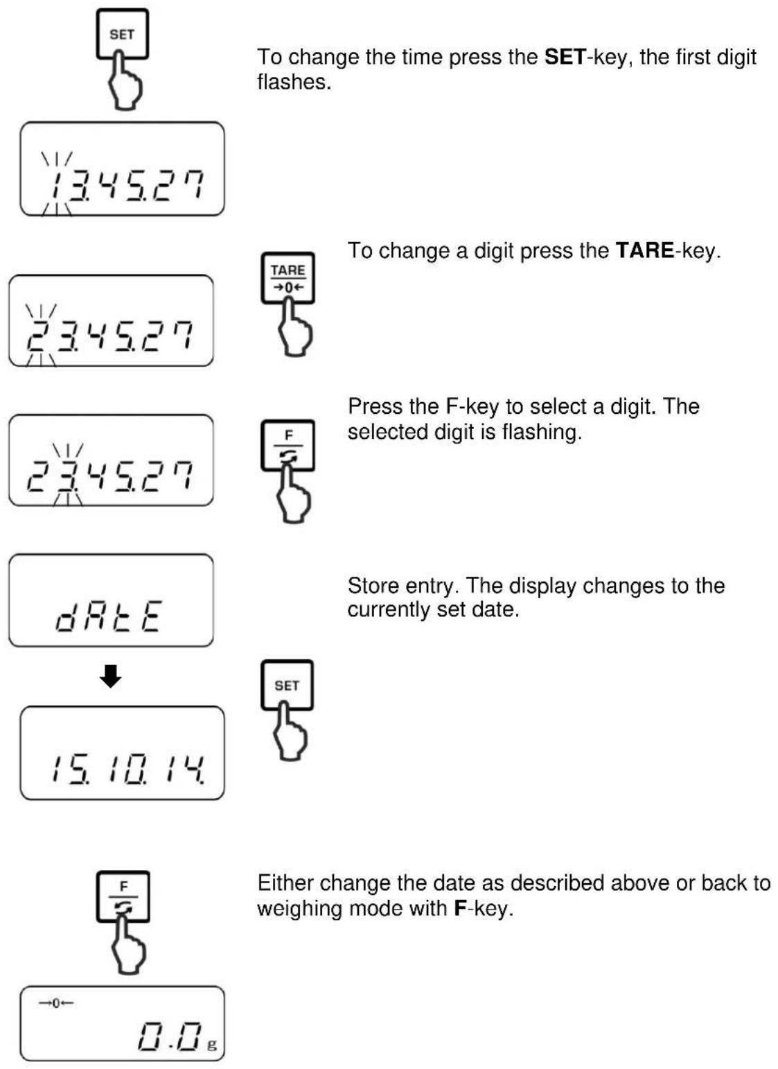
To change the time press the SET-key, the first digit flashes.
To change a digit press the TARE-key.
Press the F-key to select a digit. The selected digit is flashing.
Store entry. The display changes to the currently set date.
Either change the date as described above or back to weighing mode with F -key.
10.5.2 Setting date
text_image
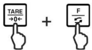
TARE →0← + FPress the F-key and the TARE-key at the same time and keep them pressed until „Func2“ will be displayed.
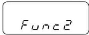
When released, „1.CrC. 0.“ is displayed.

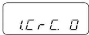
Press F-key repeatedly until „3.d.St.0“ is displayed.
3.d.5±.0
Use the TARE-key to select „3.d.St.1“.
3d5t.1
Press F-key. „tiME“ is displayed, followed by the current set time.
E , RE
13.45.27
flowchart
graph TD
    A["Hand icon: F/2"] --> B["DATE"]
    B --> C["15.10.14"]
    C --> D["SET button"]
    D --> E["15.10.14"]
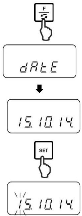
Press F-key. „dAtE“ is displayed, followed by the currently set date.
To change the date press the SET-key, the first digit flashes.
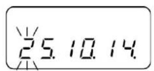
text_image
25.10.14.
To change a digit press the TARE-key.
text_image
25.10.14.
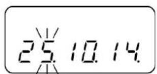
Press the F-key to select a digit. The selected digit is flashing.
Store entry The balance returns to weighing mode
10.6 Set date format

flowchart
graph TD
    A["F"] --> B["Func"]
    B --> C["1.6.0.1"]
    C --> D["F"]
    D --> E["b.dA t.3"]
    E --> F["TARE →0←"]
    F --> G["b.dA t.1"]
    G --> H["TARE →0←"]
    H --> I["b.dA t.2"]
    I --> J["SET"]
    J --> K["-0← 0.0 g"]
Press the F-key and keep pressed until „Func“ is displayed.
When releasing the button, the first function „1.b.G., is displayed with the current setting.
Press repeatedly the F-button until „b.dAt“ appears with the current setting.
Use the TARE-key to select the desired setting.
Save / back to weighing mode
Confirm setting with SET-key.
The balance returns to weighing mode.
11 RS232C-interface
11.1 General hints
For the connection of a peripheral device (printer, computer) the balance is as per series equipped with a RS232C-interface.
The following conditions must be met to provide successful communication between the weighing balance and the peripheral devices.
- Connect balance using a suitable cable with the interface of the peripheral device. Faultless operation requires an adequate KERN interface cable.
- Communication parameters (baud rate, bits and parity) of balance and peripheral device must match.
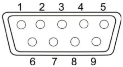
Pin allocation of the balance output plug (Sub-D, 9 poles):
text_image
1 2 3 4 5 6 7 8 9| Pin nr. | Signal | Input/Output | Function |
| 1 | - | ||
| 2 | RXD | Input | Receive data |
| 3 | TXD | Output | Transmit data |
| 4 | DTR | Output | HIGH |
| 5 | GND | - | Signal ground |
| 6 | - | - | |
| 7 | - | - | |
| 8 | - | - | |
| 9 | - | - |
Interface cable:
• Balance – PC 9-pole
| PCD-SUB9P | BalanceD-SUB9P | ||
| TXD | 3 | 2 | RXD |
| RXD | 2 | 3 | TXD |
| GND | 5 | 5 | GND |
| DCD | 1 | ||
| RTS | 7 | ||
| CTS | 8 | ||
| DSR | 6 | ||
| DTR | 4 | ||
Technical data
- Baud rate 1200*/2400/4800/9600/19200 bps
- Transmission code ASCII codes (8/7 bits)
- Bit setting Start bit 1 bit
Data bits 8 bits
Parity bit 0* / 1 bit
Stop bits 1 bit
- Parity None*/Odd/Even
Factory settings are marked by *.
Interface parameters

The available interface parameters are only shown when function [7 K.F1] or [7 K.F2] is enabled.
➢ Factory settings are marked by *.
| Menu item |  |  | Description | |
| Output condition | 71. Q.m. | 0 | No data output | |
| 1 | Continuous data output | |||
| 2 | Continuous data output stable weighing values | |||
| * 3 | Output of stable and instable weighing values after pressing PRINT key | |||
| 4 | Output with stable weighing value after previous relief of balance | |||
| 5 | One output with stable weighing value. No output with stable weighing values. Renewed output after stabilization | |||
| 6 | One output with stable weighing value. Continuous output with instable weighing values. | |||
| * 7 | Output of stable weighing values after pressing PRINT key | |||
| Baud rate | 7r B.L. | * 1 | 1200 bps | |
| 2 | 2400 bps | |||
| 3 | 4800 bps | |||
| 4 | 9600 bps | |||
| 5 | 19200 bps | |||
| Parity | 7s PA. | * 0 | No parity bit | During setting only [7 K.F 2] |
| 1 | Odd parity | |||
| 2 | Even parity | |||
11.2 Printer operation
Make sure that the balance is connected to the printer interface by a suitable cable and the communication parameters (baud rate, bits and parity) of balance and printer are matching.
11.2.1 Edit an ISO/GLP/GMP-conform adjustment log (only models PNJ)
Quality assurance systems require printouts of weighing results as well as of correct adjustment of the balance stating date and time and balance identification. The easiest way is to have a printer connected.
flowchart
graph TD
    A["F/2"] --> B["Func"]
    B --> C["1.60.1"]
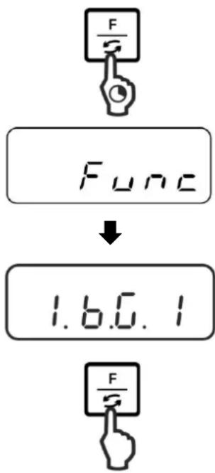
Press the F-key and keep pressed until „Func“ is displayed.
When releasing the button, the first function „1.b.G., is displayed with the current setting.
Press repeatedly the F-button until „0.GLP.“ with the current setting is displayed.
Use the TARE-key to select the desired setting.
„0.GLP.0“ Adjustment protocol output de-activated
„0.GLP.1“ Adjustment protocol output activated
text_image
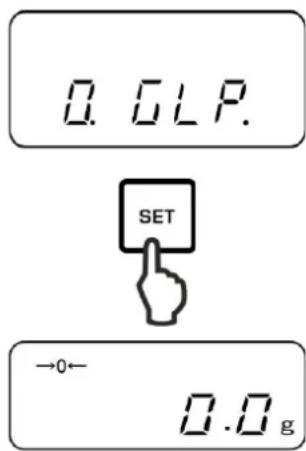
0.0 L.P. SET →0← 0.0 gSave / back to weighing mode:
Confirm setting with SET-key.
The balance returns to weighing mode.
Sample protocol (KERN YKB-01N):
CALIBRATION
KERN & SOHN
MODEL:
PNJ 3000-2M
S/N 190001833
ID:
DATE: 15.09.2015
TIME: 10:27
*CAL.END
NAME:

11.2.2 Protocol output with current date / time
Press the F-key and keep pressed until „Func“ is displayed.

When releasing the button, the first function „1.b.G., is displayed with the current setting.
Press repeatedly the F-button until „C.t.o.“ appears with the current setting.
Use the TARE-key to select the desired setting.
„C.t.o.0“ Edit weighing value without date / time
„C.t.o.1“ Edit weighing value with time
„C.t.o.2“ Edit weighing value with date + time
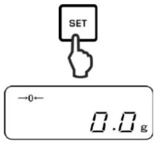
text_image
SET →0← 0.0 gSave / back to weighing mode
Confirm setting with SET-key.
The balance returns to weighing mode.
Sample protocols (KERN YKB-01N)
„C.t.o. 0“
+0075.55 G S
„C.t.o. 1“
09:48:39
+0075.55 G S
„C.t.o. 2“
17.09.2015
09:48:39
+0075.55 G S
11.3 Data output
11.3.1 Data transmission format
You can adapt the format of data transfer (6 or 7 digits) to your requirements in the menu.
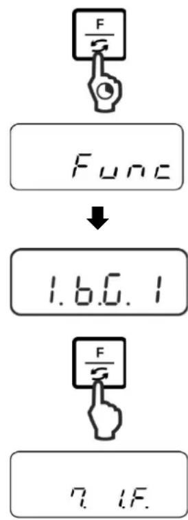
flowchart
graph TD
    A["F/2"] --> B["Func"]
    B --> C["1.6.0.1"]
    C --> D["F/2"]
    D --> E["7.1.F."]
Press the F-key and keep pressed until „Func“ is displayed.
When releasing the button, the first function „1.b.G., is displayed with the current setting..
Press F-key repeatedly until „7.I.F.“ with the current setting is displayed.
Use the TARE-key to select the desired setting.
„7.I.F.1“ 6-digit data format
„7.I.F.2“ 7-digit data format
„7.I.F.3“ 6-digit data format (ASCII)
„7.I.F.4“ 7-digit data format (ASCII)
(In models PNJ 1 and 2 they are unavailable)
Save / back to weighing mode:
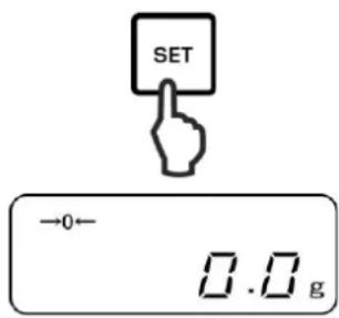
text_image
SET →0← 0.0 gConfirm setting with SET-key.
The balance returns to weighing mode.
6-digit data format, consisting of 14 characters, including terminator; CR=0DH, LF=0AH (CR=weighing balance reverse / LF=line indent).
| 1 | 2 | 3 | 4 | 5 | 6 | 7 | 8 | 9 | 10 | 11 | 12 | 13 | 14 |
| P1 | D1 | D2 | D3 | D4 | D5 | D6 | D7 | U1 | U2 | S1 | S2 | CR | LF |
7-digit data format, consisting of 15 characters, including terminator; CR=0DH, LF=0AH (CR=weighing balance reverse / LF=line indent). A parity bit can be appended.
| 1 | 2 | 3 | 4 | 5 | 6 | 7 | 8 | 9 | 10 | 11 | 12 | 13 | 14 | 15 |
| P1 | D1 | D2 | D3 | D4 | D5 | D6 | D7 | D8 | U1 | U2 | S1 | S2 | CR | LF |
6-digit data format (ASCII), consisting of 15 characters, including terminator; CR=0DH, LF=0AH (CR=weighing balance reverse / LF=line indent). The oblique “/” is printed just before the last digit.
| 1 | 2 | 3 | 4 | 5 | 6 | 7 | 8 | 9 | 10 | 11 | 12 | 13 | 14 | 15 |
| P1 | D1 | D2 | D3 | D4 | D5 | D6 | D7 | D8 | U1 | U2 | S1 | S2 | CR | LF |
7-digit data format (ASCII), consisting of 15 characters, including terminator; CR=0DH, LF=0AH (CR=weighing balance reverse / LF=line indent). A parity bit can be appended. The slash “/” is printed just before the last digit.
| 1 | 2 | 3 | 4 | 5 | 6 | 7 | 8 | 9 | 10 | 11 | 12 | 13 | 14 | 15 | 16 |
| P1 | D1 | D2 | D3 | D4 | D5 | D6 | D7 | D8 | D9 | U1 | U2 | S1 | S2 | CR | LF |
11.3.2 Description of data
Signs
[P1] (1 character)
| P1 | Code | Significance |
| + | 2 B H | Data is 0 or positive |
| - | 2 D H | Data is negative |
Numeric value of weighing value
[D 1 to D7(D 8)] (7 or 8 characters
| D 1 to D 8 | Code | Significance |
| 0 - 9 | 30 H – 39 H | Data 0 to 9 |
| • | 2 EH | Decimal point, position not fixed |
| SP | 20 H | Space character, leading zero suppressed |
| / | 2FH | Non verified value separated by „/“(only with menu setting [A. PrF. 3]) |
Units
[U 1, U 2] 2 digits
| U1 | U2 | ASCII code | Significance | Display | |
| (SP) | G | 20H | 47H | Gram | g |
| C | T | 43H | 54H | Carat | ct |
| O | Z | 4FH | 5AH | Ounce | oz |
| L | B | 4CH | 42H | Pound | lb |
| O | T | 4FH | 54H | Troy ounce | oz t |
| D | W | 44H | 57H | Pennyweight | dvt |
| G | R | 4BH | 52H | Grain | ►Bottom right |
| T | L | 54H | 4CH | Tael (Hong Kong) | tI |
| T | L | 54H | 4CH | Tael (Singapore, Malaysia) | [ti]►Upper right ] |
| T | L | 54H | 4CH | Tael (Taiwan) | [ti]►Bottom right ] |
| M | O | 4DH | 4FH | Momme | (mom) |
| t | o | 74H | 6FH | Tola | to |
| (SP) | % | 20H | 25H | Percent determination | % |
| P | C | 50H | 43H | Parts counting | Pcs |
Tolerance weighing
[S1] (1 character)
| S 2 | Code | Significance | Remarks |
| L | 4CH | Load below specified tolerance | 1- or 2 end points |
| G | 47H | Load within specified tolerance | |
| H | 48H | Goods to be weighed above tolerance limit | |
| (SP) | 20 H | No evaluation result / space character |
Data status
[S2] (1 character)
| S 2 | Code | Significance |
| S | 53 H | Data stabilized * |
| U | 55 H | Data not stabilized (fluctuating) * |
| E | 45 H | Data error, all data apart from S 2 not allowed.Balance indicating error (o-Err, u-Err) |
| (SP) | 20 H | No status / space character |
11.3.3 Output examples
Examples 6-digit data format:
➢ Stable weighing value [3000.1g]
| 1 | 2 | 3 | 4 | 5 | 6 | 7 | 8 | 9 | 10 | 11 | 12 | 13 | 14 |
| + | 0 | 3 | 0 | 0 | 0 | . | 1 | (SP) | G | (SP) | S | CR | LF |
Instable weighing value [-10.05 mom]
| 1 | 2 | 3 | 4 | 5 | 6 | 7 | 8 | 9 | 10 | 11 | 12 | 13 | 14 |
| - | 0 | 0 | 1 | 0 | . | 0 | 5 | M | O | (SP) | U | CR | LF |
Examples 7-digit data format:
▶ Stable weighing value [3000.1g]
| 1 | 2 | 3 | 4 | 5 | 6 | 7 | 8 | 9 | 10 | 11 | 12 | 13 | 14 | 15 |
| + | 0 | 0 | 3 | 0 | 0 | . | 1 | (SP) | G | (SP) | S | CR | LF |
▶ Instable weighing value [-10.05 mom]
| 1 | 2 | 3 | 4 | 5 | 6 | 7 | 8 | 9 | 10 | 11 | 12 | 13 | 14 | 15 |
| - | 0 | 0 | 0 | 1 | 0 | . | 0 | 5 | M | O | (SP) | U | CR | LF |
11.4 Remote control instructions
General order format:
Consisting of 4 characters including the terminators (CR, LF).
| C1 | C2 | CR | LF |
Subsequent commands will be detected by the weighing scale.
1. Data output
| C1 | C2 | Code (C1) | Code (C2) | Function | Response |
| O | 0 | 4FH | 30H | No data output | A00: Free from errorE01: Error message |
| O | 1 | 4FH | 31H | Continuous data output | |
| O | 2 | 4FH | 32H | Continuous data output stable weighing values | |
| O | 3 | 4FH | 33H | Output for stable and instable weighing values after pressing PRINT key | |
| O | 4 | 4FH | 34H | Output for stable weighing value after previous relief of balance | |
| O | 5 | 4FH | 35H | One output for stable weighing value. No output for stable weighing values. Renewed output after stabilization | |
| O | 6 | 4FH | 36H | One output for stable weighing value. Continuous output for instable weighing values. | |
| O | 7 | 4FH | 37H | Output of stable weighing values after pressing PRINT key | |
| O | 8 | 4FH | 38H | Single immediate output | |
| O | 9 | 4FH | 39H | Single output after stabilization |
2. Taring / Setting to zero
| C1 | C2 | Code (C1) | Code (C2) | Function | Response |
| T | (SP) | 54H | 20H | Taring (>1,5 % Max)Zero setting (< 1,5 % Max) | A00: Free from errorE01: Error message |
| T | T | 54H | 31H | Taring | A00: Free from errorE01: Error messageE04: Taring range exceeded |
| Z | (SP) | 5AH | 20H | Zeroing | A00: Free from errorE01: Error messageE04: Zero range exceeded |
3. Internal adjustment
| C1 | C2 | Code (C1) | Code (C2) | Function | Response |
| C | 1 | 43H | 31H | Carry out internal adjustment | A00: Free from errorE01: Error messageE02: Order cannot be carried out |
4. Query date / time
| C1 | C2 | Code (C1) | Code (C2) | Function | Response |
| D | D | 44H | 44H | Query date | DATE : d d . m m . y y y y (CR, LF)Date format depends on menu setting [b.dat.], see chap. 0 |
| D | T | 44H | 54H | Query time | TIME:(SP) (SP) (SP) (SP) (SP) h h : m m (CR, LF) |
11.5 Response formats
Consisting of 5 characters, including the end characters (CR=0DH, LF=0AH)*.
| 1 | 2 | 3 | 4 | 5 |
| A1 | A2 | A3 | CR | LF |
* End character: CR = paragraph, LF = line
Commands:
| A1 | A2 | A3 | Code (A1) | Code (A2) | Code (A3) | Description |
| A | 0 | 0 | 41H | 30H | 30H | Normal response |
| E | 0 | 1 | 45H | 30H | 31H | Incorrect responset |
12 Servicing, maintenance, disposal

Before any maintenance, cleaning and repair work disconnect the appliance from the operating voltage.
12.1 Cleaning
Please do not use aggressive cleaning agents (solvents or similar agents), but a cloth dampened with mild soap suds. Ensure that no liquid penetrates into the device.
Polish with a dry soft cloth.
Loose residue sample/powder can be removed carefully with a brush or manual vacuum cleaner.
Spilled weighing goods must be removed immediately.
12.2 Servicing, maintenance
⇒ The appliance may only be opened by trained service technicians who are authorized by KERN.
→ Before opening, disconnect from power supply.
12.3 Disposal
Disposal of packaging and appliance must be carried out by operator according to valid national or regional law of the location where the appliance is used.
13 Instant help
In case of an error in the program process, briefly turn off the balance and disconnect from power supply. The weighing process must then be restarted from the beginning.
Help:
| Fault | Possible cause |
The displayed weight does not glow.
- The balance is not switched on.
- The mains supply connection has been interrupted (mains cable not plugged in/faulty).
• Power supply interrupted.
The displayed weight is permanently changing
- Draught/air movement
- Table/floor vibrations
- Weighing pan has contact with other objects.
- Electromagnetic fields / static charging (choose different location/switch off interfering device if possible)
The weighing result is obviously incorrect
- The display of the balance is not at zero
- Adjustment is no longer correct.
- The balance is on an uneven surface.
- Great fluctuations in temperature.
- Warm-up time was ignored.
- Electromagnetic fields / static charging (choose different location/switch off interfering device if possible)
14 Error messages
Error Possible cause message
| o-Err | Weighing range exceeded |
| u-Err | Insufficient preload, e. g. missing weighing pan |
| 1-Err | Wrong adjustment weight (>80% max) |
| 2-Err | Divergence last external adjustment > 1% |
| 3-Err | Weighing pan loaded during adjustment |
| 4-Err | Divergence from last internal adjustment > 1% |
| A-Err | Internal adjustment automatics defective |
| b-Err | Check ambient conditions (static charges, vibration, etc.) |
| C-Err | Internal clock defective |
| d-Err | Damaged electronics |
| L-Err | Placed weight too light, e.g. for reference calculation during parts counting or percentage determination |
| Err 710 | Instable environmental conditions |
Should other error messages occur, switch balance off and then on again. If the error message remains inform manufacturer.
15 Declaration of conformity
To view the current EC/EU Declaration of Conformity go to:
www.kern-sohn.com/ce
i The scope of delivery for verified weighing balances (= conformity-rated weighing balances) includes a Declaration of Conformity.
KERN PNJ / PNS
Version 1.5 2024-03
text_image
Technical diagram of an experimental balance with numbered parts for identificationtext_image
Technical diagram of a digital balance or analog device with numbered components labeled for identification.Pos. Désignation
text_image
KERN PNJ + TOL - ON OFF PRINT M SET F S TARE →0←natural_image
Line drawing of a digital balance scale with a small rectangular component on top (no text or symbols)Balance
natural_image
Simple line drawing of a square frame with dashed lines indicating hidden edges (no text or symbols)natural_image
Technical line drawing of a four-pronged mechanical component with mounting holes (no text or symbols)natural_image
Isometric line drawing of a 3D mechanical housing or enclosure with mounting holes and internal components (no text or symbols)text_image
Diagram showing two mechanical components with labeled parts and directional arrows indicating assembly or movement.2
natural_image
Pure mechanical diagram showing a frame with three screwdrivers and directional arrows, no text or symbols present.3
natural_image
Technical line drawing of a mechanical assembly with an inset showing a close-up detail (no text or symbols)4
⇒ Fixer le panneau frontal.
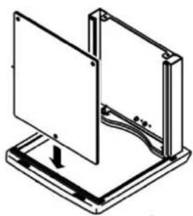
natural_image
Isometric line drawing of a mechanical assembly with a rectangular frame and base plate (no text or symbols)text_image
Technical diagram of a mechanical assembly with labeled component M4, showing a close-up view of a bracket and mounting bracket.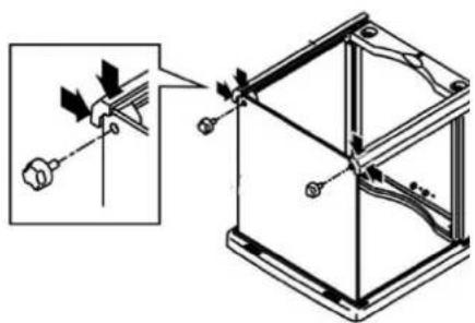
text_image
Technical diagram showing a mechanical assembly with tool application and close-up of the component, including Chinese annotations.6
natural_image
Isometric line drawing of a 3D cube with internal compartments and directional arrows, no text or symbols present7
natural_image
Technical line drawing of a mechanical housing with two vertical supports and internal components (no text or symbols)9
natural_image
Technical line drawing of a mechanical assembly with an inset showing a close-up of a bracket and a close-up of a vertical panel (no text or symbols present)11
natural_image
Close-up of a white plastic electronic device with internal components and mounting bracket (no visible text or symbols)natural_image
Illustration of a digital laboratory balance scale with a circular component above it (no text or symbols)Modèles d = 0,001g

natural_image
Line drawing of a digital balance scale with an open lid and control panel (no text or symbols)natural_image
Line drawing of a mechanical setup with a cube and digital scale, showing a downward trend from top to bottom (no text or symbols)natural_image
Technical line drawing of a mechanical device with two views showing internal components and directional arrows (no text or symbols)natural_image
Line drawing of a digital balance scale with two circular gauges and a pointer, no text or symbols present.Pieds à vis
natural_image
Line drawing of a hand pressing down on a steaming appliance (no text or symbols)natural_image
Empty rectangular frame with a small asterisk symbol in the top-left corner (no text or numbers)
natural_image
Simple line drawing of a hand pressing down on a steaming appliance (no text or symbols)natural_image
Technical line drawing of a device rear panel with labeled components (no text or symbols beyond labels)Modèles d = 0,001g
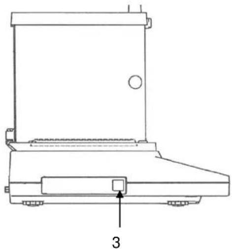
natural_image
Technical line drawing of a mechanical device with labeled component '3' (no text or symbols beyond label)natural_image
Technical line drawing of a mechanical component with no visible text or symbolstext_image
→0← 0 | | | F 0.0 g▶ Avertissement surcharge
text_image
SET →0← 0.0 gflowchart
graph TD
    A["Device with 3 spheres"] --> B["600.0 g"]
    B --> C["TARE →0←"]
    C --> D["Net 0.0 g"]
    D --> E["Image of 3 spheres in a tray"]
    E --> F["1000.0 g"]
text_image
Pcs M on 30text_image
SET Pcs M on 30 Pcs M 60text_image
SET M Pcs 6.0flowchart
graph TD
    A["SET"] --> B["M"]
    B --> C["P SET"]
text_image
+ TOL - ° 93.73 g 0 I I I F
text_image
TOL + - 0 I I I F 100.73g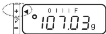
text_image
+ TOL - 0 I I I F 107.03 g2. Réglage de menu „23.Pi. 1“ / une valeur seuil
text_image
+ TOL - ° 93.73 g 0 I I I F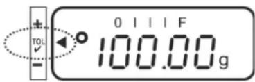
text_image
TOL - 0 I I I F 100.00 gPas d'information
text_image
0 I I I F 0.00 g SET L.SETtext_image
PRINT M 0 I I I F 95.00 gtext_image
+ TOL - ° 93.73 g 0 I I I F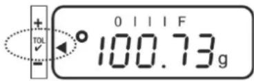
text_image
TOL + - 0 I I I F 100.73g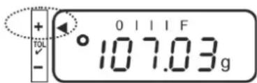
text_image
+ 107.03g -5.
text_image
0 I I I F 0.00 g SET L.SET 70.00 g TARE →0← 70.00 g 0 I I I F 95.00 g- Parité None*/Odd/Even