
SKSUD2402P - Fridge SIGNATURE - Free user manual and instructions
Find the device manual for free SKSUD2402P SIGNATURE in PDF.

| Product Type | Convertible Drawer Refrigerator Under-Counter Built-In |
| Brand | Signature Kitchen Suite |
| Model | SKSUD2402P |
| Dimensions (W x H x D) | 602 x 870-880 x 590 mm (with panel) |
| Power Supply | 115 V, 60 Hz, 15 A |
| Ambient Temperature | 13 °C to 43 °C |
| Main Functions | Convertible temperature zone, double drawers, customization with decorative panels |
| Installation | Built-in under counter, requires cutout of 610 x 876 mm min. |
| Noise Level | Not specified, reasonable estimate ≤ 45 dB |
| Climate Class | Not specified, suitable for standard indoor use |
| Maintenance and Cleaning | Clean with a soft cloth and soapy water. Do not use abrasive cleaners. |
| Safety | Anti-tip devices, grounding, dedicated outlet |
| Spare Parts and Repairability | Optional stainless steel panel set (SKSUK240DS, SKSUK240WS). Optional handles (SKSHK230HS). |
| General Information | 92-page manual available for free download. Compatible with Smart Diagnosis (Wi-Fi). |
Frequently Asked Questions - SKSUD2402P SIGNATURE
User questions about SKSUD2402P SIGNATURE
0 question about this device. Answer the ones you know or ask your own.
Ask a new question about this device
Download the instructions for your Fridge in PDF format for free! Find your manual SKSUD2402P - SIGNATURE and take your electronic device back in hand. On this page are published all the documents necessary for the use of your device. SKSUD2402P by SIGNATURE.
USER MANUAL SKSUD2402P SIGNATURE

INSTALLATION MANUAL
BUILT-IN REFRIGERATOR
Read this installation manual thoroughly before installing the appliance and keep it handy for reference at all times.
ENGLISH
SKSUD2402P / SKSUW2401P
MFL67410830
Rev.01_071423
www.signaturekitchensuite.com
Copyright © 2021-2023 Signature Kitchen Suite. All Rights Reserved.


natural_image
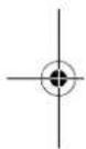
Pure geometric diagram with intersecting lines and circular shapes, no text or symbols present2
TABLE OF CONTENTS
3 IMPORTANT SAFETY INSTRUCTIONS
3 WARNING
3 Installation
3 Electrical Connection
4 C A U T I O N
4 General
5 INSTALLATION
5 Before Installation
5 Choosing the Install Location
5 Anti-tip Devices
5 Enclosure
5 F l o o r
5 Electrical Requirements
6 Grounding
6 Cutout Dimensions
7 Installation Clearances
8 Required Accessories and Tools
8 Accessories
8 Tools
9 Product Dimensions
9 Product Dimensions
11 Custom Panel Dimensions
12 Moving Appliance into Enclosure
12 Installing the Anti-tip Brackets
13 Protecting Edges of Enclosure
13 Installing Appliance in Enclosure
15 Leveling and Securing the Appliance
15 Aligning and Leveling the Appliance
17 Attaching Appliance to Enclosure
18 Attaching the Toe Kick Panel
20 Panels and Trim
20 Installing Door Panels
22 Adjusting Door Panels
22 Installing Door Trim
26 Reversing the Door
27 Attaching the Badge
28 Inserting the Link Assembly


natural_image
Pure geometric diagram with intersecting lines and circular shapes, no text or symbols presentIMPORTANT SAFETY INSTRUCTIONS
WARNING
• TIP-OVER HAZARD
- The appliance is very heavy. If it tips over, it could cause damage, serious injury or death. Do not open the doors or drawers before the appliance is securely installed.
- Use two or more people to move and install the refrigerator. To prevent the refrigerator from tipping over, install anti-tip brackets (provided). Failure to follow the refrigerator installation instructions can result in serious injury or death.
- To reduce the risk of fire, electric shock, or personal injury when using the product, basic safety precautions should be followed, including the following. Read all instructions before using this appliance.
Installation
• These products are not designed to be used as freestanding units. Doing so will result in a risk of tipover, personal injury, and product or property damage.
- Do not install the refrigerator near a gas stove, water heater or other source of ignition that may possibly leak gas. Do not install product in direct sunlight. Install the product in a well ventilated area.
- Ensure that enclosure dimensions allow for sufficient air circulation at the sides and back of the product. Do not block the front air inlet. Failure to follow these instructions may cause product malfunction.
- Enclosure must be constructed of materials which are strong enough to avoid damage during installation and frequent use.
- Cabinet materials must be able to withstand the heat and humidity produced during product operation and use without twisting or deforming.
• Install the product on a firm, level surface that can support the weight of the product without bending. The product must be level both horizontally and vertically.
- Keep children away from area during installation.
- Do not use an extension cord or power strip with this product.
- Do not install the refrigerator in a damp location or where it will be exposed to running water. Deterioration of the insulation on electrical parts may result, causing risk of electric shock.
- Connect to potable water only. Non-potable water can cause health risks.
Electrical Connection
- If connected to a circuit protected by fuses, use time delay fuse.
- Use a dedicated outlet.
- Plugging several devices into one outlet may cause a fire.
- Plug in the power plug with the power cord facing downward.
- Failure to do so could damage the plug or cord, resulting in fire or electric shock.
- When installing or moving the refrigerator, be careful not to roll over or damage the power cord. Do not squeeze or crush the cord or plug when pushing the refrigerator in.
- Doing so could result in fire or electric shock.
- Do not allow the power cord to be bent, crushed, or damaged. Do not run the power cord under heavy objects like furniture, other appliances, or through high-traffic areas.
- Doing so may damage the power cord and result in fire or electric shock.
- Do not extend or modify the length of the power cord.
- Use only an exact factory replacement part to avoid electrical issues, fire, or electric shock.


4 IMPORTANT SAFETY INSTRUCTIONS
- Turn off the power before cleaning or moving the refrigerator.
- Failure to do so may cause electric shock or injury.
- Press the POWER button for 3 seconds to turn off the power at the display panel.
- Do not pull out the cord or touch the power plug with wet hands.
- Doing so may cause electric shock or injury.
- Remove water or dust from the power plug and insert it securely into the wall socket.
- Dust, water, or a loose connection may cause a fire or electric shock.
- Do not unplug the refrigerator by pulling on the cord.
- Doing so may cause an electric shock or a short circuit resulting in a fire.
- Do not use the power cord or the power plug if it is damaged or if the outlet is damaged.
- Doing so may cause an electric shock or a short circuit resulting in a fire.
- Wait for 5 minutes or longer when reconnecting the plug or turning the power back on.
- Give the compressor time to cycle before restarting.
- If the supply cord is damaged, it must be replaced by the manufacturer or its service agent or a similarly qualified person in order to avoid a hazard.
CAUTION
- Do not stick your hands under the refrigerator.
- Sharp edges, fans, and wires may cause an injury.
- Save these instructions for the local inspector's use.
- Observe all governing codes and ordinances.
• Installer: Leave these instructions with the consumer. - Consumer: Keep these instructions with the owner's manual for future reference.
General
These installation instructions are intended for use by qualified installers. All connections for water, electrical power and grounding must comply with local codes and ordinances and be made by licensed personnel when required. In the absence of a local code:
- In the U.S.A., in accordance with the National Electric Code, ANSI/NFPA70 – latest edition/State and Municipal codes and/or local codes.
- In Canada, in accordance with the Canadian Electric Code C22.1 – latest edition/Provincial and Municipal codes and/or local codes.
SAVE THESE INSTRUCTIONS


INSTALLATION
Before Installation

WARNING
- Do not store or install the appliance where it will be exposed to:
- outside weather
- water damage
- temperatures under 32 °F (0 °C)
Choosing the Install Location
Temperature and Humidity
• The appliance should be installed in a dry, well ventilated area.
• The ambient temperature should stay between 55 °F (13 °C) and 110 °F (43 °C), to avoid malfunctions.
- Do not install product where it will be exposed to direct sunlight or near a heat source, such as an oven or radiator.
Anti-tip Devices

WARNING
- Tip Hazard
- The appliance is very heavy and may tip over if the door is opened before the appliance is securely installed.
- Install the supplied anti-tip brackets to prevent the appliance from tipping. The safest method of installing the appliance in a stable position is to use the supplied anti-tip devices.
- Do not open the appliance door unless it is still on the pallet or the anti-tip brackets are engaged.
- If the enclosure is sturdy enough, attaching the appliance to the upper and side walls of the enclosure may provide additional stability, as long as the enclosure is firmly connected to the back wall. If in doubt, contact an architect or structural engineer.
Enclosure
- The panel above the appliance must be made from a solid material (not MDF) and at least 5/8" (16 mm) thick.
- The side walls of the cavity or enclosure must be flush.
- The front 4 inches (100 mm) of the interior surface (furniture return) will be visible when doors are open. Make sure this area is finished to at least 4 inches deep.
- Follow the specifications for the installation enclosure to ensure a trouble free installation.
- Above all, the enclosure cannot be out of square. Use a spirit level or measure the diagonals of the opening to make sure corners are square.
• The appliance is attached at the sides and the top to either the enclosure or to adjacent cabinets. Make sure the enclosure or the adjacent cabinets are securely connected to the floor or wall structures.
Floor

WARNING
- The floor in the installation area must be firm, level, and rigid for safe installation and best performance.
- Do not install the appliance on a platform or raised structure.
• The structure underneath the appliance must be able to support the weight of the appliance without tilting or flexing. - For best performance and to avoid leakage, level the appliance.
Electrical Requirements

WARNING
• Electrical Shock Hazard
- Plug into a grounded 3-prong outlet.
- Do not remove ground prong.
- Do not use an adapter.
-
Do not use an extension cord.
-
Failure to follow these instructions can result in death, fire, or electrical shock.
- Follow all state and local codes or NEC.
• The appliance comes with a UL listed 3-wire power supply cord.
• The appliance requires a 3-wire receptacle.


natural_image
Pure geometric diagram with intersecting lines and circles, no text or symbols present6 INSTALLATION

WARNING
- The receptacle must be installed by a licensed electrician only.
Grounding
This appliance must be grounded. In the event of a malfunction or breakdown, grounding will reduce the risk of electric shock by providing a path of least resistance for the electric current.

WARNING
- Improper connection of the equipment grounding conductor may result in electric shock. Have the appliance checked by a qualified electrician or service technician if you are in doubt as to whether the appliance has been properly grounded.
NOTE
- Some local regulations may require a separate ground. In such cases, the required ground wire, clamp and screw are available as a separate accessory and must be purchased separately.
- Never ground the appliance to plastic plumbing lines, gas lines or water pipes.
Cutout Dimensions

CAUTION
- The anti-tip bracket should be firmly fixed to a concrete wall/wood with strength of 15 t or greater, or a wall with equivalent strength. (The structure where the bracket is fixed should be a solid structure that can withstand a force of 70 kgf or greater.)
- Before installing the appliance, make sure that the enclosure is the correct size. For the appliance to operate properly, the notch in the
bottom front plate must be aligned with the center of the appliance.
SKSUD2402P
SKSUW2401P
| - SKSUD2402P SKSUW2401P | |
| A | ≥24" (610 mm) |
| B | ≥24" (610 mm) |
| C | ≥34 1/2" (876 mm) |
| D 4" (101 mm) | |
| E 23 11/16" (602 mm) | |
| F 30 5/16" (770 mm) | |
- A minimum 4" (101 mm) finished return that matches the cabinet exterior is recommended on all sides and at the top of the cutout opening. The shaded area will be visible after installation.


Electrical
- A 115 V, 60 Hz, 15 amp power supply is required. An individual, properly grounded branch circuit or circuit breaker is recommended. Install a properly grounded 3-prong electrical receptacle recessed into the back wall. Electrical must be located on rear wall as shown.
- When installing a single product, use a single outlet.
NOTE
- GFCI (ground fault circuit interrupter) is not recommended.
natural_image
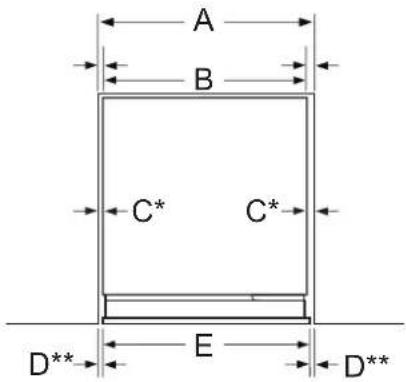
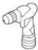
Technical line drawing of a mechanical device with attached tubing and housing (no text or symbols)Installation Clearances
Model: SKSUD2402P
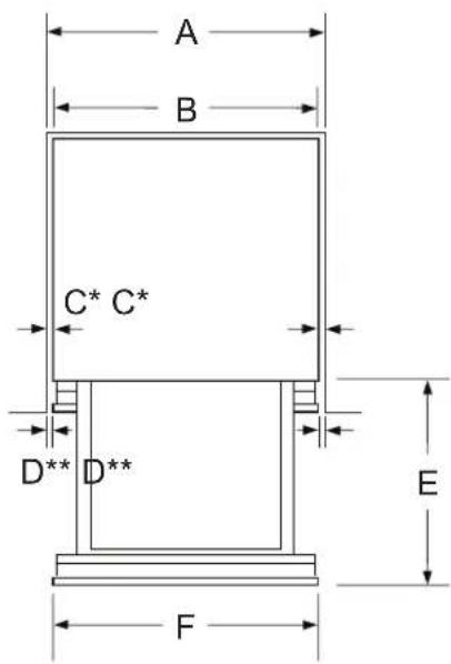
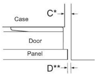
* Side clearance at cabinet
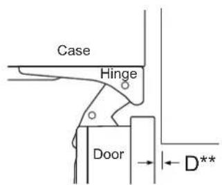
** Side clearance at front panel
| - Dimensions and Clearances | |
| A | ≥24" (610 mm) |
| B 23 7/16" (595 mm) | |
| C 5/16" (7.5 mm) min. | |
| D 3/16" (4 mm) | |
| E 18" (457 mm) with panel | |
| F 23 11/16" (602 mm) with panel | |
ENGLISH
Model: SKSUW2401P
* Right hand hinge installation shown. When reversing the door, the hinge and handle side clearances also reverse.
** Side clearance at front panel
Top View (Door Closed)
Top View (Door Open 90°)


8 INSTALLATION
Top View (Door Open 115°)
| - Dimensions and Clearances | |
| A | ≥24" (610 mm) |
| B 23 7/16" (595 mm) | |
| C | Handle Side 1/8" (2.5 mm) min.Hinge Side 1/2" (12.5 mm) min. |
| D 3/16" (4 mm) | |
| E 23 11/16" (602 mm) with panel | |
| F | 1 / |
NOTE
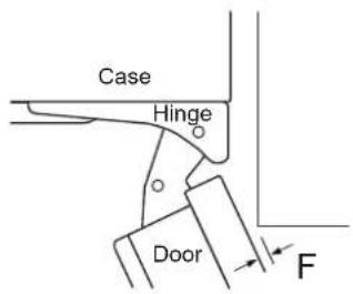
• Door Swing Clearances
- The installation must allow for clearances to adjacent walls or cabinets. This wine refrigerator is equipped with a 2-position door stop. The factory-set 115° door swing can be adjusted to 90° if clearance to adjacent cabinets or walls is restricted.
• Door Handle Clearances
- The door handle depth must be added to the dimension as noted to determine the total clearances required from adjacent cabinets or walls. This clearance will vary depending on the custom handle used. When using the Stainless Steel Door Panel Kit w/ Stainless Steel Handle, the door handle clearance with door open 115° is 11 3/4" (298 mm).
Required Accessories and Tools
Accessories
Supplied Accessories
• Installation instructions
- Operating instructions
- Installation kit
| Screw Size No. Used for | |||
| [SC16]A Type | 5H x 45L | 6 Anti-tip bracket | |
| [WZZA]B Type | 4D x 14L | 10 | Anti-tip bracket (6)Enclosure (4) |
| [own7]C-1 Type | 4D x 6L | 4 | En |
| [oss3]C-2 Type | 4D x 12L | 12 Door panel | |
NOTE
- In addition to the quantity required for installing the appliance, spare screws may be provided.
Other
• Dolly, hand truck
- Drill for drilling holes in wall or floor.
- Drill bits in various sizes and suitable for materials
- Wood screws in different sizes
- Thin plywood sheet, particle board or cardboard to protect the floor from damage
- Suitable material for covering and protecting furniture (e.g. protective sheets)
- Adhesive tape
Tools
 | Cordless screwdriver |
 | Torx bit T20, T30 and magnetic holder |
 | Torx screwdriver T20, T30 |
 | 3/8" (10 mm) hex nut driver |
 | Various drill bits |


natural_image
Pure geometric diagram with intersecting lines and circular shapes, no text or symbols present | Multigrip pliers |
 | Adjustable wrench |
 | Cutter with adjustable blade |
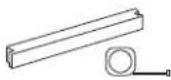 | Metal tape measure, folding rule |
 | Square |
 | Level, length 2" (60 cm) and 4' (1.2 m) |
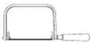 | Saw to cut top trim pieces (for retrofit installation only) |
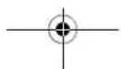
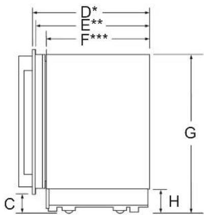
- Side View
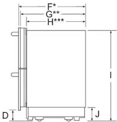
* Depth with 3/4" (19 mm) drawer panel
** Depth with drawers (no panel)
*** Unit depth without drawers
| - Dimensions | |
| A | 23 11/16" (602 mm) with panel23 7/16" (595 mm) without panel |
| B 15" (381 mm) | |
| C 1/4" (7 mm) | |
| D 4" (101 mm) | |
| E | 34 1/4" (870 mm) min.34 5/8" (880 mm) max. |
| F 23 1/4" (590 mm) | |
| G 22 1/2" (571 mm) | |
| H 20 1/2" (520 mm) | |
| I | 33 3/16" (843 mm) min.33 9/16" (853 mm) max. |
| J 5" (128 mm) | |
Product Dimensions
The following installation instructions describe the installation steps for various appliance types.
The diagrams may be a general representation of your appliance.
Particular reference is made to special installation steps for individual appliance types.
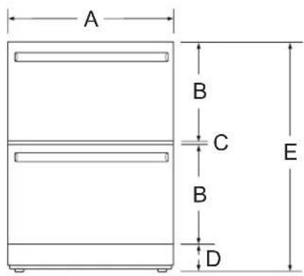
Product Dimensions
Model: SKSUD2402P
- Front View


natural_image
Pure geometric diagram with intersecting lines and circles, no text or symbols present
10 INSTALLATION
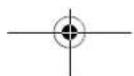
Model: SKSUW2401P
- Front View
- Side View
• Top View (Door Open 90°)
• Top View (Door Open 115°)
* Depth with 3/4" (19 mm) drawer panel
** Depth with door (no panel)
*** Unit depth without door
| - Dimensions | |
| A 23 11/16" (602 mm) with panel | |
| B | 34 1/4" (870 mm) min.34 5/8" (880 mm) max. |
| C 4" (101 mm) | |
| D 23 5/8" (600 mm) | |
| E 22 7/8" (581 mm) | |
| F 20 7/8" (530 mm) | |
| G | 33 3/16" (843 mm) min.33 9/16" (853 mm) max. |
| H 5" (128 mm) | |
* Door handle must be added to this dimension.
** Varies depending on the thickness of the custom cabinet panel. The door panels in the optional Signature Kitchen Suite stainless steel door panel kit are 3/4" (19 mm) thick.
| - Dimensions | |
| I 23 7/16" | (595 mm) |
| J 20 7/8" | (530 mm) |
| K 26 1/8" | (663 mm) |
| L 10 1/2" | (266 mm) |
| M 24 3/8" | (620 mm) |


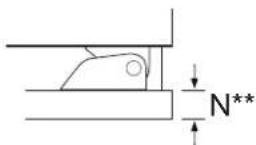
natural_image
Pure geometric diagram with intersecting lines and circular shapes, no text or symbols present| - Dimensions | |
| N 3/4" (19 mm) |
NOTE
- This unit is designed to be customized with a decorative panel. A field-installed custom door panel or an optional Stainless Steel Panel Kit is required.
- For Custom Panels: Use templates provided with units to pre-drill holes for mounting panel brackets (provided with unit). Adjustment screws and instructions are also provided with units.
• 24-inch built-in undercounter wine refrigerator
ENGLISH
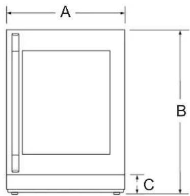
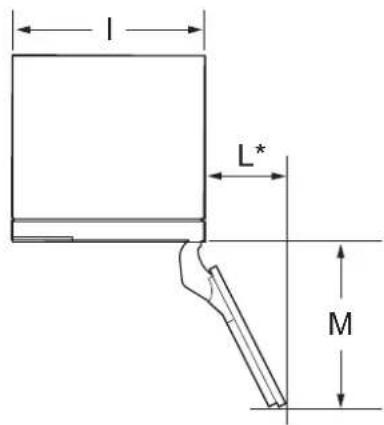
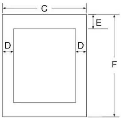
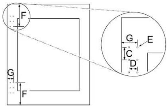
Custom Panel Dimensions
3/4" (19 mm) Custom panel dimensions – Flush installation
• 24-inch undercounter convertible drawer refrigerator
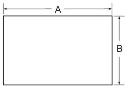
| - Dimensions |
| A 23 11/16" (602 mm) |
| B 15" (381 mm) |
NOTE
- The custom panel dimensions are the same for the upper and lower drawers.
| - Dimensions | |
| C 23 1/16" | (602 mm) |
| D 3 11/32" | (84.9 mm) |
| E 4 15/16" | (124.9 mm) |
| F 30 9/32" | (769 mm) |
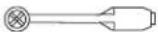
SKS door handle installation dimensions of custom panel
• 24-inch undercounter convertible drawer refrigerator
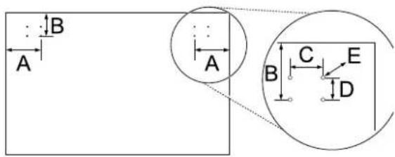
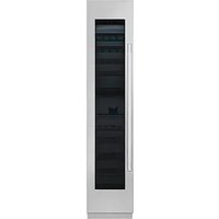
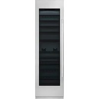
• 24-inch built-in undercounter wine refrigerator


natural_image
Pure geometric diagram with intersecting lines and circular shapes, no text or symbols present12 INSTALLATION
| - Dimensions | |
| A 3 3/4" (94.5 mm) | |
| B 2 7/16" (62.4 mm) | |
| C 1 7/16" (37 mm) | |
| D 15/16" (24.4 mm) | |
| E Φ 3/16" (4.8 mm) | |
| F 7" (178 mm) | |
| G 1 1/4" (57.9 mm) | |
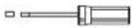
Optional Accessories
• SKSUK240DS - Stainless Steel Panel and Handle Kit for 24-inch Undercounter Drawer Refrigerator
- This unit can be installed with an optional Stainless Steel Panel Kit. Kit includes two drawer panels and two handles.
• SKSUK240WS - Stainless Steel Panel and Handle Kit for 24-inch Undercounter Wine Refrigerator
- This unit can be installed with an optional Stainless Steel Panel Kit. Kit includes door panel and handle.
- SKSHK230HS - Handles for use with custom panel
- 22 3/4" (578 mm) medium brushed aluminum handle
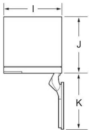
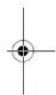
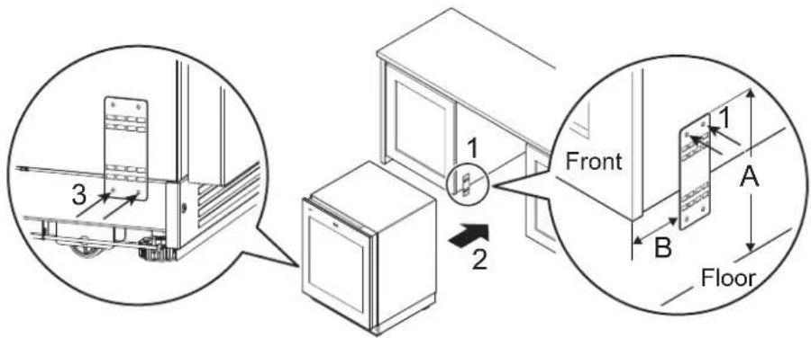
Moving Appliance into Enclosure
Installing the Anti-tip Brackets

WARNING
• To avoid injury or damage, check for electrical wires or plumbing in walls before drilling or installing screws.
- The anti-tip bracket should be firmly fixed to a concrete wall/wood with strength of 15 t or greater, or a wall with equivalent strength. (The structure where the bracket is fixed should be a solid structure that can withstand a force of 70 kgf or greater.)
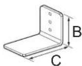
Install the anti-tip brackets at the rear of the enclosure, locating the brackets based on stud locations and product and enclosure dimensions.
Anti-Tip Bracket x 2
| - Dimensions | |
| A | 33 3/16" (843 mm) min.33 9/16" (853 mm) max. |
| B 2 3/8" (60 mm) | |
| C 3 3/4" (90 mm) | |
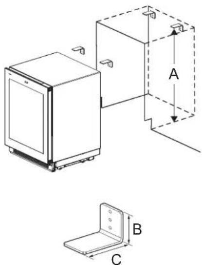
NOTE
- Brackets must be attached as shown below. The brackets could fail to prevent tipover of the unit if installed in an alternate orientation.
natural_image
Technical line drawing of a mechanical bracket assembly with three corner brackets and no text or symbols


natural_image
Pure geometric diagram with intersecting lines and circular shapes, no text or symbols present- Use A type or B type screws. (Recommended: Concrete wall A Type, Wood wall B Type)
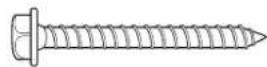
A Type

B Type
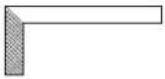
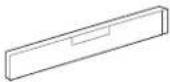
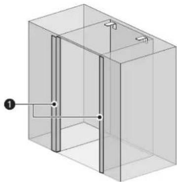
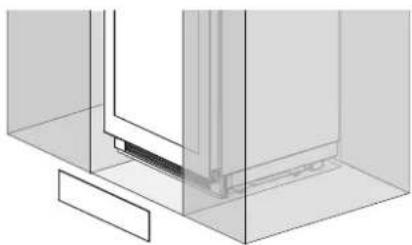
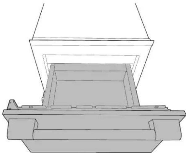
Protecting Edges of Enclosure
To protect the front edges of the enclosure, tape thin cardboard or some other protective material around the edges.
natural_image
3D diagram of a rectangular enclosure with internal vertical and horizontal lines, no text or symbols present① Protective cover
Installing Appliance in Enclosure

WARNING
- Use 2 or more people when installing the appliance. Take care when moving the appliance. It is very heavy and prone to tipping when not secured.

CAUTION
• Take care to avoid damaging the water line or power cord when moving the appliance into the enclosure.
- Before moving the unit into position, secure the door/drawers closed and protect any finished flooring.
- Use an appliance dolly to move the unit near the opening.
- The front leveling legs are extended below the front rollers to improve stability during placement. Once the unit is placed in front of the opening, completely retract the front leveling legs to allow the unit to be rolled into position. Front and rear leveling legs can be adjusted from the front once the unit is positioned.
- If the unit has been on its back or side, it must stand upright for a minimum of 24 hours before turning on the power.


natural_image
Pure geometric diagram with intersecting lines and a central circular pattern (no text or symbols)14 INSTALLATION

CAUTION
• After the appliance is rolled into position, verify that the anti-tip brackets are properly engaged.
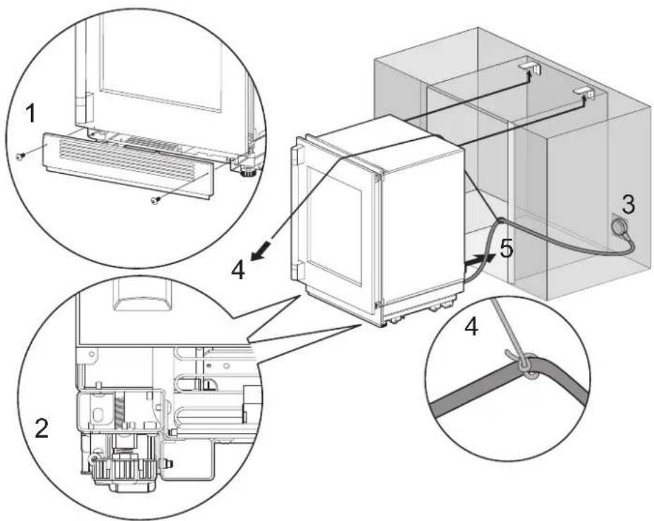
1 Remove the base panel.
2 Retract the leveling legs so the appliance can be wheeled forward.
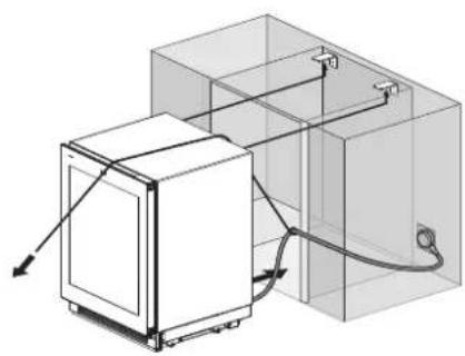
3 Plug the power cord into the outlet.
4 Tie a long string around the middle of the power cord. Feed the string over the top of the appliance, pull it until the power cord is held high off the ground, then tape the string to the front of the appliance to hold the power cord off the ground. Do not pinch or strain the power cord. Make sure it is still plugged in.
5 Carefully move the appliance into the enclosure, making sure not to pinch the power cord or water line under or behind the appliance.
6 Remove the string from the power cord and the edge protection on the enclosure.
1 Remove the base panel.
2 Retract the leveling legs so the appliance can be wheeled forward.
3 Plug the power cord into the outlet.
4 Tie a long string around the middle of the power cord. Feed the string over the top of the appliance, pull it until the power cord is held high off the ground, then tape the string to the front of the appliance to hold the power cord off the ground. Do not pinch or strain the power cord. Make sure it is still plugged in.
5 Carefully move the appliance into the enclosure, making sure not to pinch the power cord or water line under or behind the appliance.
6 Remove the string from the power cord and the edge protection on the enclosure.


natural_image
Pure geometric diagram with intersecting lines and circles, no text or symbols presentLeveling and Securing the Appliance
Aligning and Leveling the Appliance
- Depth Adjustment
- Adjust the depth of the unit in the enclosure so the door panels will fit flush with the surrounding cabinetry. Use the gauge tool provided for a precise fit.
- Height Adjustment
- The front and rear leveling legs can both be adjusted from the front.
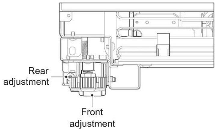

- Leveling
- Once the appliance is aligned properly in the enclosure, level it using the front and rear leveling legs.
1 Use a Phillips screwdriver and wrench to extend the front and rear leveling legs until they are in firm contact with the floor.
2 Turn the screws as shown above to raise the appliance. Turn the screws in the opposite direction to lower the appliance.
3 Make sure the weight of the refrigerator is carried on the legs, not the wheels.


16 INSTALLATION
4 Use a smartphone leveling app or place a carpenter's level on the top and sides of the appliance to check that it is level and plumb. Or use the provided gauge tool to measure the distance of the bottom edge of the appliance from the floor at the front corners.
WARNING
- To reduce the possibility of the unit tipping forward, the front leveling legs must be in contact with the floor.
CAUTION
- If using a power drill, use the lowest torque setting.
- Leave at least 3/8 inch (10 mm) between the top front of the appliance and the top of the enclosure to fit the top filler strip.
- Do not exceed 20 inch-pounds (2.25 Nm) of torque.
- 20 revolutions equal 1/16'' (2 mm) of height adjustment.
Attaching Appliance to Enclosure
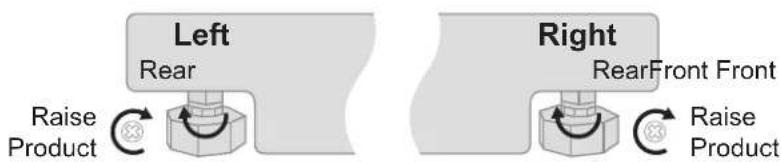
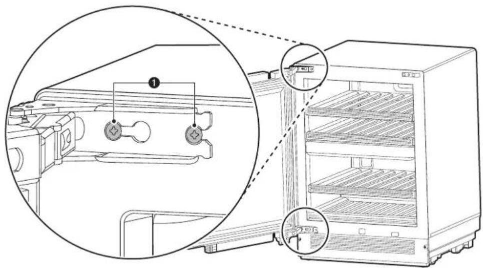
- Tighten the side fixing bracket to the bottom left and right sides of the cabinet using the B type and C-1 type screws.
- Use the B type screw to fix the bracket to the cabinet and use the C-1 type screw to attach the bracket to the appliance.
natural_image
Technical line drawing of a mechanical assembly with two circular views showing internal components (no text or symbols)ENGLISH
- If there is not enough space to tighten the screw on the side by the baseboard, attach the bracket to the bottom of the adjoining cabinet.

natural_image
Technical line drawing of a mechanical assembly with mounting brackets and a rail-mounted bracket (no text or symbols)- If the mounting bracket is attached to the cabinet first:
1 Attach the bracket to the cabinet using a B type screw.
2 Insert the appliance, level the appliance with the adjoining cabinet, and secure the appliance by extending the front and rear legs.
18 INSTALLATION
3 After securing the appliance, attach the bracket to the refrigerator using a C-1 type screw.
| - Dimensions | |
| A 6 11/16" (170 mm) | |
| B 5 5/16" (135 mm) |
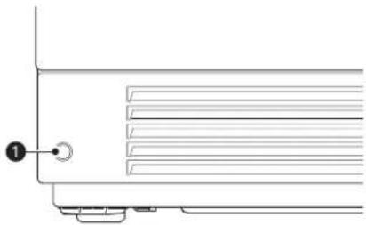
Attaching the Toe Kick Panel

CAUTION
- Do not close the air vent in the bottom cover of the appliance.
natural_image
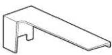
Pure technical line drawing of a mechanical assembly or mounting bracket (no text or symbols)1 Use a screw ① to attach the bottom cover to the appliance.
natural_image
Pure technical line drawing of a mechanical component with no text or symbols2 Attach the Smart Diagnosis label ② in the location shown.


natural_image
Pure geometric diagram with intersecting lines and circular shapes, no text or symbols present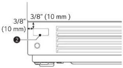
ENGLISH
NOTE
- The Wi-Fi transmission and reception unit is located on the baseboard, so the reception may depend on the baseboard material.
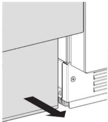
• Finishing the baseboard installation
- If the position (depth from the front) of the cabinet baseboard is different from the position of the appliance baseboard, adjust the cabinet baseboard so that it is aligned with the position of the appliance baseboard.
• To adjust the baseboard
- Pull the cabinet baseboard forward and align it with the refrigerator baseboard.
natural_image
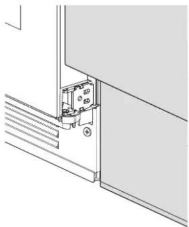
Pure technical diagram of a mechanical assembly with no visible text, numbers, or symbols- After adjusting the baseboard
natural_image
Technical line drawing of a mechanical assembly or mounting bracket with no visible text or symbols


natural_image
Pure geometric diagram with intersecting lines and circular shapes, no text or symbols present20 INSTALLATION
Panels and Trim
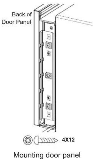
Installing Door Panels
The door panel should be installed first, followed by the upper then lower drawer panels, if needed.
1 Place the door panel face down on a protected surface.
2 Locate the correct side of the door panel template for your product and position the template flush with the top and left sides of the panel.
3 Use the template to mark the correct screw locations on the back of the panel.
4 Slide the template to the right so it is flush with the top and right sides of the panel.
5 Use the template to mark the correct screw locations on the back of the panel.
6 On refrigerator/freezer columns, begin inserting a #8 x 1/2" screw into the fifth hole from the top on each side. On wine columns, use the third hole from the top. Stop when the screws are 3/16" (4 mm) proud of the panel. These will be the support screws during the panel installation.


7 Insert the support screws in the slotted holes on the appliance door mounting brackets so that the panel is hanging on the door.

ENGLISH

CAUTION
- Beware of pinch points when installing door panels or opening and closing doors.
22 INSTALLATION
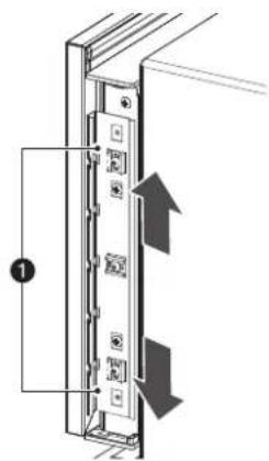
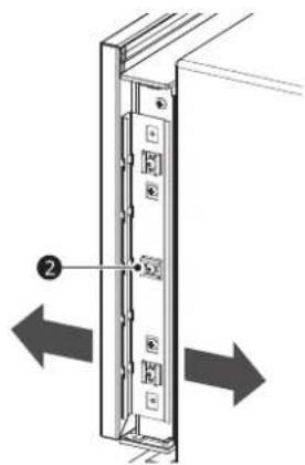
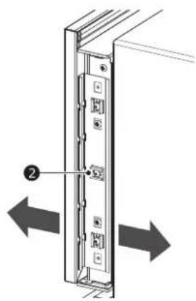
Adjusting Door Panels
Fine adjustments can now be made to align the door panels.
1 To adjust the door panel horizontally, slide the panel support screws left or right in the slotted holes as desired. Have an assistant hold the panel in place while you tighten the support screws and insert and tighten all remaining mounting screws.
2 To adjust the door panel vertically or back and forward, loosen the screws in the appliance door bracket. Move the plastic rails to make adjustments as desired. Have an assistant hold the bracket in place while you tighten all the bracket screws.
natural_image
Diagram of a server rack with two arrows indicating left and right motion (no text or symbols)①Up and down adjustment
②In and out adjustment
Installing Door Trim
Model: SKSUD2402P
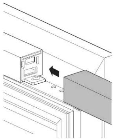
• After panels have been adjusted, install the decorative side trim on the doors.
• Install the door trim before tightening the cover using the provided screws.
① Door trim
②Cover
Model: SKSUW2401P
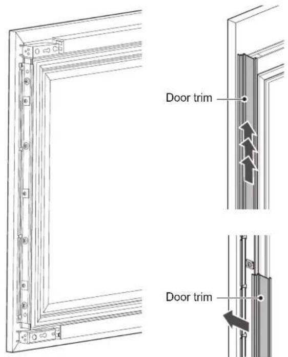
• After panels have been adjusted, install the decorative side trim on the doors.
- To install, start at the middle and align the trim with the front and rear flanges on the bracket, then snap into place by pushing the trim toward the back of the panel. Once the middle is secure, continue the installation upward until the remaining trim is completely secure.
ENGLISH
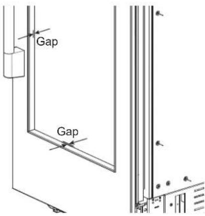
NOTE
- When adjusting the wine door panel, there will be a small gap between the surface of the glass door and the plastic panel flange. This is normal.
24 INSTALLATION
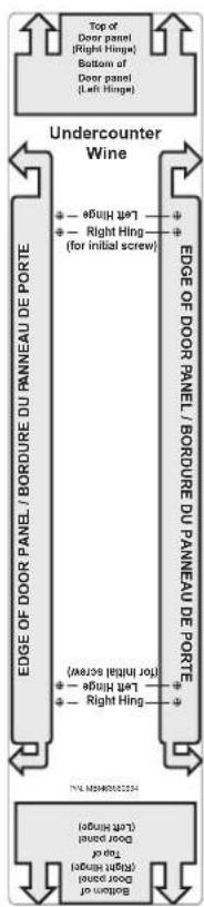
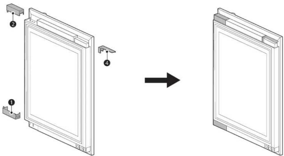
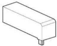
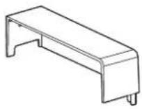
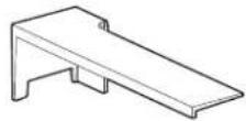
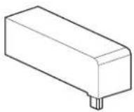
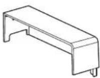
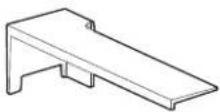
Installing the Upper and Lower Door Trim (Finish) on the Wine Model Doors
• Installing the right hinge
- Insert trim (finish) ① and ③ on the left and right side of the upper cap décor and trim (finish) ② on the left side of the lower cap décor and secure it.
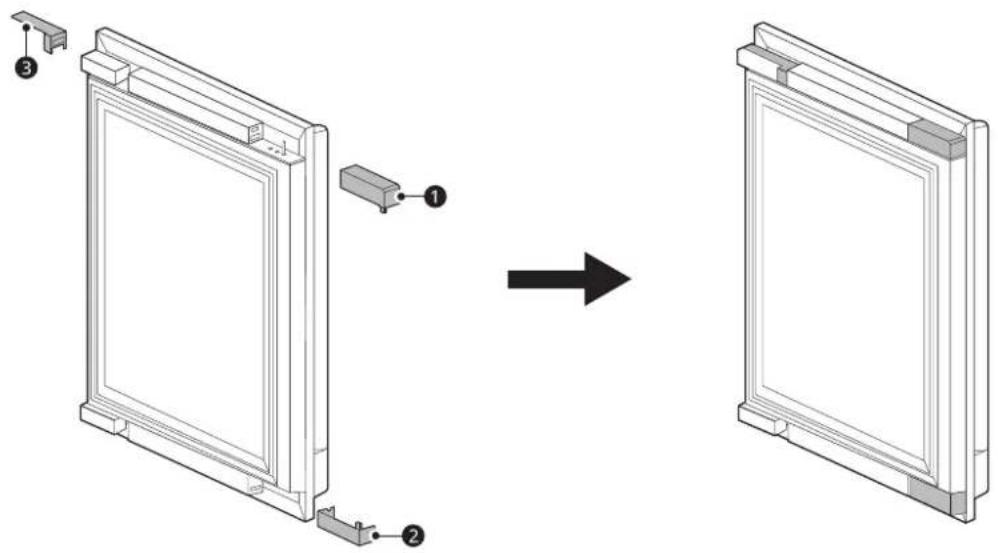
NOTE
- Insertion direction for trim
natural_image
Diagram showing a computer monitor mounted on a shelf next to a rectangular block, with an arrow indicating motion (no text or symbols present)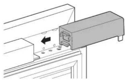
natural_image
Technical diagram of a mechanical assembly with a component and mounting holes (no text or symbols)

natural_image
Pure geometric lines and crosshair symbols without any text or labels
natural_image
Pure geometric diagram with intersecting lines and shapes, no text or symbols present
en-us_main.book.book Page 25 Friday, July 14, 2023 11:13 AM

- Installing the left hinge
- Insert trim (finish) ② and ④ on the left and right side of the upper cap décor and trim (finish) ① on the right side of the lower cap décor and secure it.
ENGLISH
| Trim 1 | Trim 2 | Trim 3 | Trim 4 |
 |  |  |  |


natural_image
Pure geometric diagram with intersecting lines and circles, no text or symbols present26 INSTALLATION
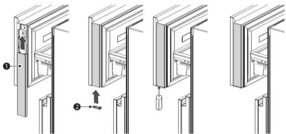
Reversing the Door
1 Remove the 2 mounting bolts Ⓞ at the top and bottom of the door. Remove the door and lay it aside on a protected surface.
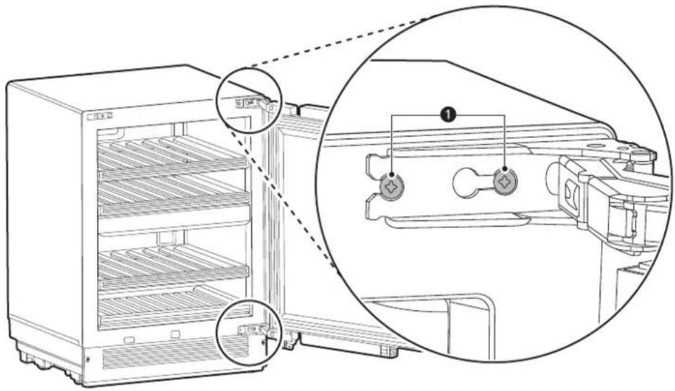
natural_image
Line drawing of an open refrigerator with internal shelves and a close-up inset showing internal components (no text or symbols)2 On the door, remove 2 bolts ② from the top hinge and install the hinge on the opposite side at the bottom of the door. On the door, remove 2 bolts ② from the bottom hinge and install the hinge on the opposite side at the top of the door.
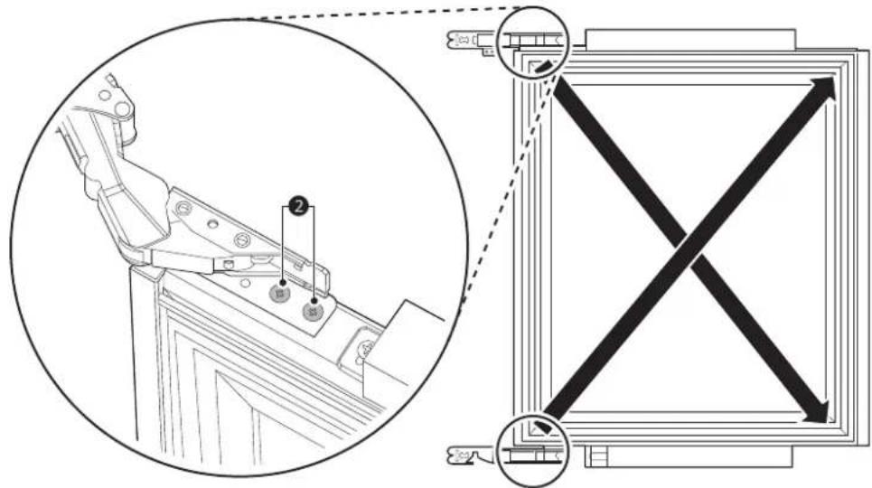
3 Insert 2 bolts ① at the top and bottom of the door to reattach the door.


ENGLISH
Attaching the Badge
Attach the following badge to a position which is 1 3/8" (35 mm) away from the bottom of the bottom door panel and 9 7/8" (251 mm) away from the right side horizontally.
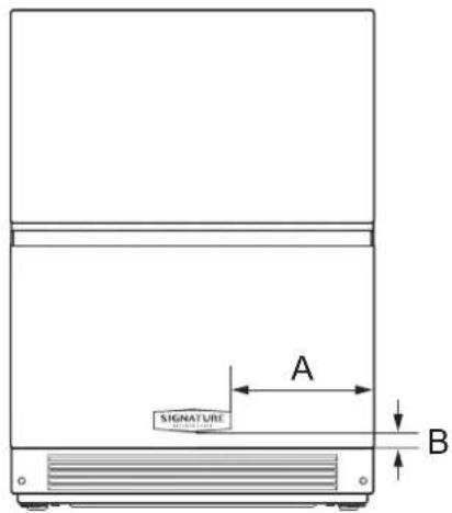
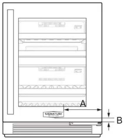
| - Dimensions | |
| A 9 7/8" (251 mm) | |
| B 1 3/8" (35 mm) |


28 INSTALLATION
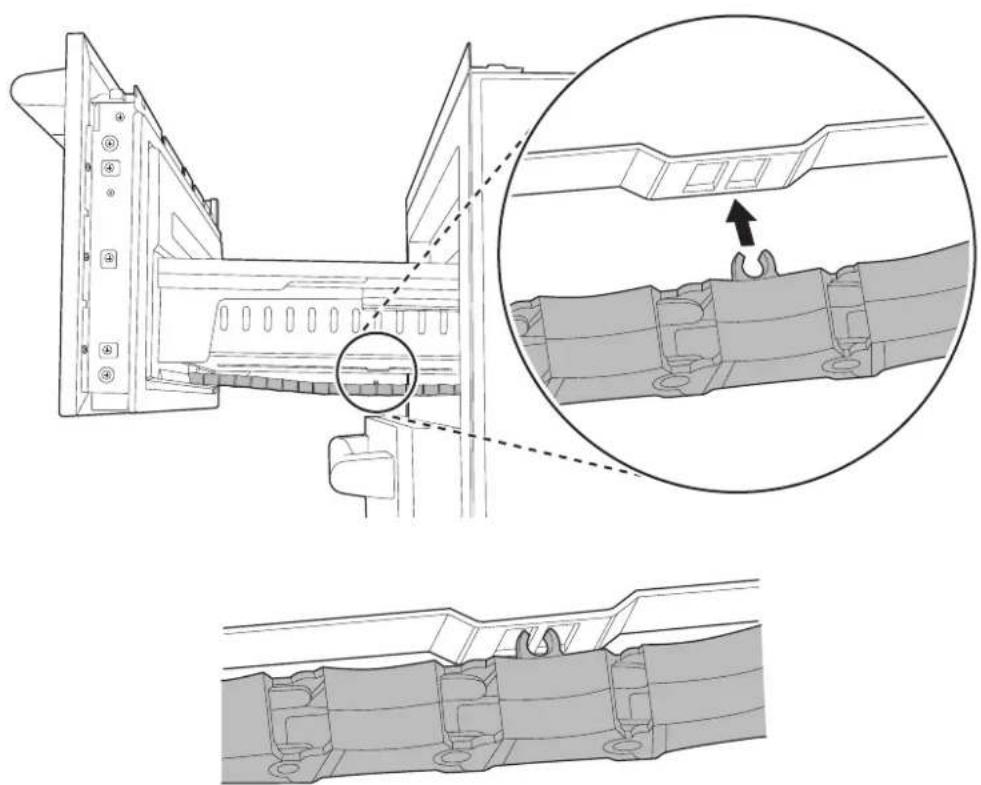
Inserting the Link Assembly
Model: SKSUD2402P
1 After installation, open the upper drawer and check that the link assembly at the bottom of the drawer is inserted.
natural_image
Technical line drawing of a mechanical assembly with layered components (no text or symbols)2 If the link assembly is not inserted, insert it at the bottom of the drawer.
natural_image
Technical diagram showing mechanical assembly with cross-section and detail views (no text or symbols)


natural_image
Pure geometric lines and crosshair symbols without any text or labels

natural_image
Pure geometric diagram with intersecting lines and shapes, no text or symbols presentSIGNATURE
KITCHEN SUITE
5 I N S T A L A C I Ó N
natural_image
Pure geometric diagram with intersecting lines and circular shapes, no text or symbols presentnatural_image
Pure geometric diagram with intersecting lines and circles, no text or symbols present6 INSTALACIÓN

ADVERTENCIA
natural_image
Technical line drawing of a mechanical device with internal components and wiring (no text or symbols)natural_image
Pure geometric diagram with intersecting lines and circular shapes, no text or symbols present| - Dimensiones | |
| I 23 7/16" | (595 mm) |
| J 20 7/8" | (530 mm) |
| K 26 1/8" | (663 mm) |
| L 10 1/2" | (266 mm) |
| M 24 3/8" | (620 mm) |
| N 3/4" (19 mm) | |
NOTA
| - Dimensiones | |
| C 23 1/16" | (602 mm) |
| D 3 11/32" | (84.9 mm) |
| E 4 15/16" | (124.9 mm) |


12 INSTALACIÓN
| - Dimensiones | |
| F 30 9/32" (769 mm) |
| - Dimensiones | |
| A 3 3/4" (94.5 mm) | |
| B 2 7/16" (62.4 mm) | |
| C 1 7/16" (37 mm) | |
| D 15/16" (24.4 mm) | |
| E Φ 3/16" (4.8 mm) | |
| F 7" (178 mm) | |
| G 1 1/4" (57.9 mm) |
natural_image
Technical line drawing of a refrigerator and cabinet with labeled dimensions (no text or symbols)


Anti-Tip Bracket x 2
| - Dimensiones | |
| A | 33 3/16" (843 mm) mín.33 9/16" (853 mm) máx. |
| B 2 3/8" (60 mm) | |
| C 3 3/4" (90 mm) | |
natural_image
Technical line drawing of a mechanical bracket assembly with three mounting holes and no text or symbols
natural_image
Isometric view of a rectangular enclosure with internal vertical and horizontal lines, no text or symbols present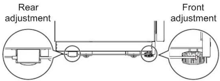
• Nivelando
natural_image
Pure geometric diagram with intersecting lines and circular shapes, no text or symbols present16 INSTALACIÓN
natural_image
Technical line drawing of a mechanical assembly with two circular views showing internal components (no text or symbols)natural_image
Technical line drawing of a mechanical assembly with mounting brackets and a rail-mounted bracket (no text or symbols)natural_image
Pure technical line drawing of a mechanical assembly or mounting bracket (no text or symbols)natural_image
Pure technical line drawing of a mechanical component with no text or symbolsnatural_image
Pure geometric diagram with intersecting lines and circular shapes, no text or symbols present
ESPAÑOL
NOTA
natural_image
Pure technical diagram of a mechanical assembly with no visible text, numbers, or symbolsnatural_image
Technical line drawing of a mechanical assembly or mounting bracket (no text or symbols visible)


20 INSTALACIÓN
Paneles y molduras
ESPAÑOL


PRECAUCIÓN
NOTA
natural_image
Technical line drawing showing two mechanical assembly configurations with arrows indicating movement (no text or symbols)


natural_image
Pure geometric lines and crosshair symbols without any text or labels
natural_image
Pure geometric diagram with intersecting lines and shapes, no text or symbols present
es-us_main.book.book Page 25 Friday, July 14, 2023 11:19 AM

ESPAÑOL
natural_image
Line drawing of an open refrigerator with internal components and a close-up view of the interior (no text or symbols)natural_image
Pure geometric lines and crosshair symbols without any text or labels

natural_image
Pure geometric diagram with intersecting lines and shapes, no text or symbols present
ESPAÑOL
natural_image
Technical line drawing of a mechanical assembly with layered components (no text or symbols)natural_image
Technical diagram showing mechanical assembly with cross-section and detail views (no text or symbols)

natural_image
Pure geometric lines and crosshair symbols without any text or labels

natural_image
Pure geometric diagram with intersecting lines and shapes, no text or symbols present

MANUEL D'INSTALLATION
RÉFRIGÉRATEUR INTÉGRÉ
natural_image
Pure geometric diagram with intersecting lines and circles, no text or symbols present
natural_image
Pure geometric diagram with intersecting lines and shapes, no text or symbols present2
TABLE DES MATIÈRES
3 CONSIGNES DE SÉCURITÉ IMPORTANTES
3 AVERTISSEMENTS
natural_image
Pure geometric diagram with intersecting lines and circles, no text or symbols presentCONSIGNES DE SÉCURITÉ IMPORTANTES
AVERTISSEMENTS
• RISQUE DE BASCULEMENT
6 INSTALLATION
INSTALLATION
natural_image
Pure geometric lines and crosshair symbols without any text or labels

natural_image
Pure geometric diagram with intersecting lines and shapes, no text or symbols present
AVERTISSEMENT
natural_image
Technical line drawing of a microwave oven connected to a wall-mounted unit (no text or symbols)| - Dimensions | |
| C 23 1/16 | po (602 mm) |
| D 3 11/32 | po (84,9 mm) |
| E 4 15/16 | po (124,9 mm) |
| F 30 9/32 | po (769 mm) |


natural_image
Pure geometric diagram with intersecting lines and circles, no text or symbols present
natural_image
Pure geometric diagram with intersecting lines and circular shapes, no text or symbols present| - Dimensions | |
| A 3 3/4 po (94,5 mm) | |
| B 2 7/16 po (62,4 mm) | |
| C 1 7/16 po (37 mm) | |
| D 15/16 po (24,4 mm) | |
| E Φ 3/16" (4.8 mm) | |
| F 7 po (178 mm) | |
| G 1 1/4 po (57,9 mm) | |
Accessoires en option
natural_image
Technical line drawing of a refrigerator with a cabinet and door, showing height dimension A (no text or symbols)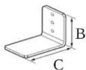
Anti-Tip Bracket x 2
| - Dimensions | |
| A | 33 3/16 po (843 mm) min.33 9/16 po (853 mm) max. |
| B 2 3/8 po | (60 mm) |
| C 3 3/4 po | (90 mm) |
REMARQUE
natural_image
Technical line drawing of a door frame structure with three bracketed metal brackets and no text or symbolsnatural_image
3D diagram of a rectangular enclosure with internal vertical and horizontal lines, no text or symbols present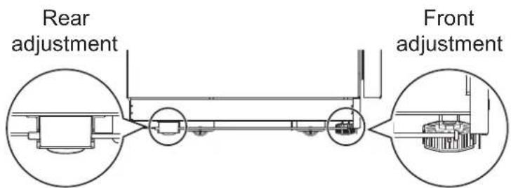
- Nivellement
natural_image
Technical line drawing of a mechanical assembly with two circular views showing internal components (no text or symbols)natural_image
Technical line drawing of a mechanical assembly with mounting brackets and a rail-mounted bracket (no text or symbols)natural_image
Pure technical line drawing of a mechanical assembly or mounting bracket (no text or symbols)natural_image
Pure technical line drawing of a mechanical component with no text or symbolsnatural_image
Pure geometric diagram with intersecting lines and circular shapes, no text or symbols present20 INSTALLATION

REMARQUE
natural_image
Pure technical diagram of a mechanical assembly with no visible text, numbers, or symbolsnatural_image
Technical line drawing of a mechanical assembly or mounting bracket with no visible text or symbols


natural_image
Pure geometric lines and crosshair symbols without any text or labels

natural_image
Pure geometric diagram with intersecting lines and shapes, no text or symbols present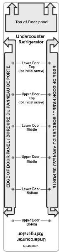


MISE EN GARDE
natural_image
Diagram of a server rack with labeled components and directional arrows indicating movement (no text or symbols present)FRANÇAIS
REMARQUE
natural_image
Technical line drawing showing two mechanical assembly configurations with arrows indicating movement (no text or symbols)


fr-ca_main.book.book Page 26 Friday, July 14, 2023 11:24 AM
26 INSTALLATION
| Garniture 1 | Garniture 2 | Garniture 3 | Garniture 4 |
 |  |  |  |


natural_image
Technical line drawing of a refrigerator internal structure with zoomed-in detail (no text or symbols)FRANÇAIS
natural_image
Technical line drawing of a mechanical assembly with no visible text or symbolsFRANÇAIS
natural_image
Technical line drawing of a mechanical assembly with cross-sectional views and an inset showing a close-up of a component (no text or symbols present)


natural_image
Pure geometric lines and crosshair symbols without any text or labels

natural_image
Pure geometric diagram with intersecting lines and shapes, no text or symbols present30 AIDE-MÉMOIRE


natural_image
Pure geometric lines forming a crosshair symbol (no text or labels)
natural_image
Pure geometric diagram with crosshair and circular shapes, no text or symbols present

natural_image
Pure geometric lines forming a crosshair symbol (no text or labels)
natural_image
Pure geometric diagram with crosshair and circular elements, no text or symbols present

natural_image
Pure geometric lines forming a crosshair symbol (no text or labels)
natural_image
Pure geometric diagram with crosshair and circular shapes, no text or symbols present
fr-ca_main.book.book Page 34 Friday, July 14, 2023 11:24 AM
34 AIDE-MÉMOIRE


natural_image
Pure geometric lines and crosshair symbols without any text or labels

natural_image
Pure geometric diagram with intersecting lines and shapes, no text or symbols present

natural_image
Pure geometric lines forming a crosshair symbol (no text or labels)
natural_image
Pure geometric diagram with crosshair and circular shapes, no text or symbols present


natural_image
Pure geometric lines forming a crosshair symbol (no text or labels)Customer Information Center
For inquires or comments, call;
1-855-790-6655 USA, Consumer User
1-888-289-2802 CANADA, Consumer User

natural_image
Pure geometric diagram with intersecting lines and shapes, no text or symbols present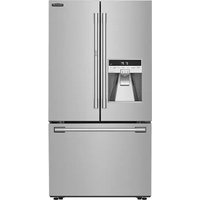
- INSTALLATION MANUAL
- BUILT-IN REFRIGERATOR
- TABLE OF CONTENTS
- IMPORTANT SAFETY INSTRUCTIONS
- WARNING
- INSTALLATION
- Before Installation
- Required Accessories and Tools
- Product Dimensions
- Moving Appliance into Enclosure
- Leveling and Securing the Appliance
- Panels and Trim
- IMPORTANT SAFETY INSTRUCTIONS
- WARNING
- Installation
- Electrical Connection
- IMPORTANT SAFETY INSTRUCTIONS
- CAUTION
- General
- SAVE THESE INSTRUCTIONS
- Before Installation
- Choosing the Install Location
- Anti-tip Devices
- Enclosure
- Floor
- Electrical Requirements
- INSTALLATION
- Grounding
- NOTE
- Cutout Dimensions
- Electrical
- Installation Clearances
- INSTALLATION
- Required Accessories and Tools
- Accessories
- Other
- Product Dimensions
- Model: SKSUD2402P
- INSTALLATION
- Model: SKSUW2401P
- Custom Panel Dimensions
- INSTALLATION
- Optional Accessories
- Moving Appliance into Enclosure
- Installing the Anti-tip Brackets
- Protecting Edges of Enclosure
- Installing Appliance in Enclosure
- INSTALLATION
- Leveling and Securing the Appliance
- Aligning and Leveling the Appliance
- INSTALLATION
- Attaching Appliance to Enclosure
- INSTALLATION
- Attaching the Toe Kick Panel
- INSTALLATION
- Panels and Trim
- Installing Door Panels
- INSTALLATION
- Adjusting Door Panels
- Installing Door Trim
- INSTALLATION
- Installing the Upper and Lower Door Trim (Finish) on the Wine Model Doors
- INSTALLATION
- Reversing the Door
- Attaching the Badge
- INSTALLATION
- Inserting the Link Assembly
- SIGNATURE
- KITCHEN SUITE
- I N S T A L A C I Ó N
- INSTALACIÓN
- ADVERTENCIA
- NOTA
- INSTALACIÓN
- INSTALACIÓN
- INSTALACIÓN
- Paneles y molduras
- PRECAUCIÓN
- MANUEL D'INSTALLATION
- RÉFRIGÉRATEUR INTÉGRÉ
- TABLE DES MATIÈRES
- CONSIGNES DE SÉCURITÉ IMPORTANTES
- AVERTISSEMENTS
- CONSIGNES DE SÉCURITÉ IMPORTANTES
- AVERTISSEMENTS
- AVERTISSEMENT
- Accessoires en option
- REMARQUE
- MISE EN GARDE
- Customer Information Center
Brand : SIGNATURE
Model : SKSUD2402P
Category : Fridge