SKSCW181RP - Fridge SIGNATURE - Free user manual and instructions
Find the device manual for free SKSCW181RP SIGNATURE in PDF.

| Product Type | Integrated Column Wine Cooler |
| Brand | Signature Kitchen Suite |
| Model | SKSCW181RP |
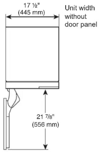
| Width (without door panel) | 17 1/2 in (445 mm) |
| Height (without door panel) | 83 1/2 in (2121 mm) - 84 1/2 in (2146 mm) |
| Depth (with 3/4 in door panel) | 24 3/4 in (629 mm) |
| Net Weight | 139 kg (306 lb) |
| Electrical Supply | 115 V, 60 Hz, 15 or 20 A |
| Installation | Flush or proud, single column or side-by-side |
| Material | Custom door panel required (3/4 in thick max 44 lb) |
| Door Opening | 115° adjustable to 90° with pin |
| Door Reversal | Possible, instructions included |
| Anti-Tip Device | Brackets supplied, fastening required |
| Leveling | Front and rear feet adjustable from the front |
| Optional Accessories | Stainless steel panel kit, frame kit, brushed aluminum handles |
| Water Connection | Not applicable (no ice maker) |
| Care and Cleaning | Clean with a soft, damp cloth; avoid abrasive cleaners |
| Spare Parts and Serviceability | Parts available from manufacturer; repair by qualified technician |
| Warranty | See manual for details |
Frequently Asked Questions - SKSCW181RP SIGNATURE
User questions about SKSCW181RP SIGNATURE
0 question about this device. Answer the ones you know or ask your own.
Ask a new question about this device
Download the instructions for your Fridge in PDF format for free! Find your manual SKSCW181RP - SIGNATURE and take your electronic device back in hand. On this page are published all the documents necessary for the use of your device. SKSCW181RP by SIGNATURE.
USER MANUAL SKSCW181RP SIGNATURE
Integrated Refrigeration Installation Guide
BUILT-IN REFRIGERATION
SKSCF1801P
SKSCF2401P SKSCR2401P
SKSCF3001P SKSCR3001P
SKSCW181RP SKSCW241RP
MFL67410824_Rev.07
www.signaturekitchensuite.com
Copyright © 2020-2023 Signature Kitchen Suite. All Rights Reserved.
Table of Contents
SAFETY INSTRUCTIONS.... 3
Before Installation 6
Choosing the Install Location 6
Installation options 9
– Dimensions and Clearances
SKSCF1801P - 18" INTEGRATED
FREEZER COLUMN
SKSCW181RP - 18" INTEGRATED
WINE COLUMN 10
SKSCF2401P - 24" INTEGRATED
FREEZER COLUMN
SKSCR2401P - 24" INTEGRATED
REFRIGERATOR COLUMN
SKSCW241RP - 24" INTEGRATED
WINE COLUMN 12
SKSCF3001P - 30" INTEGRATED
FREEZER COLUMN
SKSCR3001P - 30" INTEGRATED
REFRIGERATOR COLUMN 14
- Custom Panels
SKSCF1801P - 18" INTEGRATED
FREEZER COLUMN
SKSCW181RP - 18" INTEGRATED
WINE COLUMN 16
SKSCF2401P - 24" INTEGRATED
FREEZER COLUMN
SKSCR2401P - 24" INTEGRATED
REFRIGERATOR COLUMN
SKSCW241RP - 24" INTEGRATED
WINE COLUMN 18
SKSCF3001P - 30" INTEGRATED
FREEZER COLUMN
SKSCR3001P - 30" INTEGRATED
REFRIGERATOR COLUMN 20
Required Accessories and Tools 22
Installation 23
Unpacking 24
Moving the Appliance 25
Special Circumstances 25
Product Dimensions 26
A
Installing the Anti-tip Brackets 29
Protecting Edges of Enclosure 30
Installing Appliance in Enclosure 31
B
Aligning and Leveling the Appliance 32
Attaching the Appliance to the Enclosure ..... 34
Attaching the Toe Kick Panel 35
C
Installing Door Panels 37
Adjusting Door Panels 38
Installing Door Trim 38
Attaching Air Separator 39
– Special Installations
Optional Frame Kit Accessory 39
Adjusting the Door Spring 40
Adjusting the Door Stop 40
Water Filter Bypass 40
Reversing the Door 41
Side-by-Side Flush Installation 45
Preparing to Connect the Water Line ..... 47
Connecting the Water Line 47
Attaching the Badge 48
SAFETY INSTRUCTIONS
IMPORTANT SAFETY INSTRUCTIONS
This guide contains many important safety messages. Always read and obey all safety messages.
This is the safety alert symbol. It alerts you to safety messages that inform you of hazards that can kill or hurt you or others or cause damage to the product.
All safety messages will be preceded by the safety alert symbol and the hazard signal word WARNING, or CAUTION. These words mean:

WARNING
You may be killed or seriously injured if you don't follow instructions.

CAUTION
Indicates an imminently hazardous situation which, if not avoided, may result in minor or moderate injury, or product damage.
All safety messages will identify the hazard, tell you how to reduce the chance of injury, and tell you what can happen if the instructions are not followed.

WARNING
TIP-OVER HAZARD
Use two or more people to move and install the refrigerator. To prevent the refrigerator from tipping over, install anti-tip brackets (provided). Failure to follow the refrigerator installation instructions can result in serious injury or death.


WARNING
To reduce the risk of fire, electric shock, or personal injury when using the product, basic safety precautions should be followed, including the following. Read all instructions before using this appliance.
Installation
• These products are not designed to be used as freestanding units. Doing so will result in a risk of tipover, personal injury, and product or property damage.
- Do not install the refrigerator near a gas stove, water heater or other source of ignition that may possibly leak gas. Do not install product in direct sunlight. Install the product in a well-ventilated area.
- Ensure that enclosure dimensions allow for sufficient air circulation at the sides and back of the product. Do not block the front air inlet. Failure to follow these instructions may cause product malfunction.
- Enclosure must be constructed of materials which are strong enough to avoid damage during installation and frequent use.
- Cabinet materials must be able to withstand the heat and humidity produced during product operation and use without twisting or deforming.
• Install the product on a firm, level surface that can support the weight of the product without bending. The product must be level both horizontally and vertically. - Keep children away from area during installation.
- Do not use an extension cord or power strip with this product.
- Do not install the refrigerator in a damp location or where it will be exposed to running water. Deterioration of the insulation on electrical parts may result, causing risk of electric shock.
- Connect to potable water only. Non-potable water can cause health risks.
- If connected to a circuit protected by fuses, use time delay fuse.
Electrical Connection
Use a dedicated outlet.
- Plugging several devices into one outlet may cause a fire.
Plug in the power plug with the power cord facing downward.
Failure to do so could damage the plug or cord, resulting in fire or electric shock.
When installing or moving the refrigerator, be careful not to roll over or damage the power cord. Do not squeeze or crush the cord or plug when pushing the refrigerator in. Doing so could result in fire or electric shock.
Do not allow the power cord to be bent, crushed, or damaged. Do not run the power cord under heavy objects like furniture, other appliances, or through high-traffic areas. Doing so may damage the power cord and result in fire or electric shock.
Do not extend or modify the length of the power cord.
Use only an exact factory replacement part to avoid electrical issues, fire, or electric shock.
Turn off the power before cleaning or moving the refrigerator.
- Failure to do so may cause electric shock or injury.
- Press the POWER button for 3 seconds to turn off the power at display panel.
Do not pull out the cord or touch the power plug with wet hands.
Doing so may cause electric shock or injury.
Remove water or dust from the power plug and insert it securely into the wall socket.
Dust, water, or a loose connection may cause a fire or electric shock.
Do not unplug the refrigerator by pulling on the cord.
Doing so may cause electric shock or short circuit resulting in a fire.
Do not use the power cord or the power plug if it is damaged or if the outlet is damaged.
Doing so may cause electric shock or short circuit resulting in a fire.
Wait for 5 minutes or longer when reconnecting the plug or turning the power back on.
Give the compressor time to cycle before restarting.
If the supply cord is damaged, it must be replaced by the manufacturer or its service agent or a similarly qualified person in order to avoid a hazard.

CAUTION
Do not remove the cover of the automatic ice dispenser.
The internal mechanism of the icemaker can cause injury if handled.
Do not stick your hands under the refrigerator.
Sharp edges, fans, and wires may cause an injury
Save these instructions for the local inspector's use.
Observe all governing codes and ordinances.
Installer: Leave these instructions with the consumer.
Consumer: Keep these instructions with the owner's manual for future reference.
General
These installation instructions are intended for use by qualified installers. All connections for water, electrical power and grounding must comply with local codes and ordinances and be made by licensed personnel when required. In the absence of a local code:
- In the U.S.A., in accordance with the National Electric Code, ANSI/NFPA70 – latest edition/State and Municipal codes and/or local codes.
- In Canada, in accordance with the Canadian Electric Code C22.1 – latest edition/Provincial and Municipal codes and/or local codes.
Appliance is very heavy:
Refrigerator 30" approx. 386 lbs/175 kg
Refrigerator 24" approx. 324 lbs/147 kg
Freezer 30" approx. 403 lbs/183 kg
Freezer 24" approx. 346 lbs/157 kg
Freezer 18" approx. 304 lbs/138 kg
Wine 18" approx. 306 lbs/139 kg
Wine 24" approx. 357 lbs/162 kg
Before Installation

WARNING
Do not store or install the appliance where it will be exposed to:
- outside weather
- water damage
• temperatures under 32°F (0°C)
Choosing the Install Location
Temperature and Humidity
The appliance should be installed in a dry, well ventilated area.
The ambient temperature should stay between 55 °F(13 °C) and 110 °F(43 °C) , to avoid malfunctions.
Do not install product where it will be exposed to direct sunlight or near a heat source, such as an oven or radiator.
Anti-tip Devices
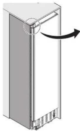
WARNING: Tip Hazard
- The appliance is very heavy and may tip over if the door is opened before the appliance is securely installed.
- Install the supplied anti-tip brackets to prevent the appliance from tipping. The safest method of installing the appliance in a stable position is to use the supplied anti-tip devices.
- Do not open the appliance door unless it is still on the pallet or the anti-tip brackets are engaged.
If the enclosure is sturdy enough, attaching the appliance to the upper and side walls of the enclosure may provide additional stability, as long as the enclosure is firmly connected to the back wall. If in doubt, contact an architect or structural engineer.
Enclosure
- The panel above the appliance must be made from a solid material (not MDF) that is at least 5/8" (16 mm) thick.
- The side walls of the cavity or enclosure must be flush.
- The front 4 inches (100 mm) of the interior surface (furniture return) will be visible when doors are open. Make sure this area is finished to at least 4 inches deep.
- Follow the specifications for the installation enclosure to ensure a trouble free installation.
- Above all, the enclosure cannot be out of square. Use a spirit level or measure the diagonals of the opening to make sure corners are square.
- The appliance is attached at the sides and the top to either the enclosure or to adjacent cabinets. Make sure the enclosure or the adjacent cabinets are securely connected to the floor or wall structures.
Floor

WARNING
- The floor in the installation area must be firm, level, and rigid for safe installation and best performance.
- Do not install the appliance on a platform or raised structure.
- The structure underneath the appliance must be able to support the weight of the appliance without tilting or flexing.
- For best performance and to avoid leakage, level the appliance.
Electrical Requirements

WARNING
Electrical Shock Hazard
- Plug into a grounded 3 prong outlet.
- Do not remove ground prong.
- Do not use an adapter.
- Do not use an extension cord.
Failure to follow these instructions can result in death, fire, or electrical shock.
Follow all state and local codes or NEC.
The appliance comes with a UL listed 3 wire power supply cord.
The appliance requires a 3-wire receptacle.
The receptacle must be installed by a licensed electrician only.
Grounding
This appliance must be grounded. In the event of a malfunction or breakdown, grounding will reduce the risk of electric shock by providing a path of least resistance for the electric current.
WARNING: Improper connection of the equipment grounding conductor may result in electric shock. Have the appliance checked by a qualified electrician or service technician if you are in doubt as to whether the appliance has been properly grounded.
NOTE
Some local regulations may require a separate ground. In such cases, the required ground wire, clamp and screw are available as a separate accessory and must be purchased separately.
Never ground the appliance to plastic plumbing lines, gas lines or water pipes.
Water Connection

CAUTION
- Connect the appliance to potable water only.
- A cold water connection is required for operation of the automatic ice maker. The water pressure must be between 20 and 120 psi. (1.38-8.27).
- The installation must comply with local plumbing regulations.
- A separate shut-off valve must be installed for the appliance water connection.
- Do not use a self-piercing valve.
- Do not install the shutoff valve for the water behind the appliance. The shutoff valve must be easily accessible.
- Install the water connection in the area shown in the diagram under Dimensions and Clearances. The water supply line can be located on the right side, on the left side, or in the floor. The maximum outer diameter of the supply line (without fittings) is 3/8" (9.5 mm).
Installation options
There are many different installation options.
These are limited only by the design of the kitchen.
Individual Appliance
Side-by-Side (Pair)
Individual Appliances with Partition
Minimum thickness of the partition 5/8" (16 mm)
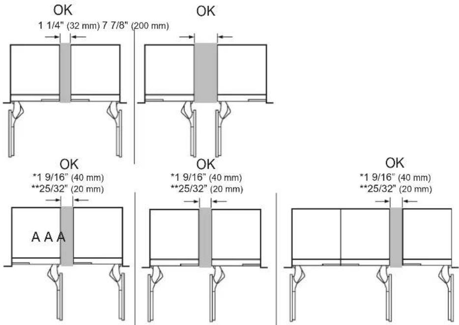
* When not using 90° door stop pin
** When using 90° door stop pin on the A product
SKSCF1801P - 18" INTEGRATED FREEZER COLUMN
SKSCW181RP - 18" INTEGRATED WINE COLUMN
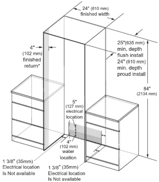
CUTOUT DIMENSIONS – FLUSH OR PROUD INSTALLATION, SINGLE COLUMN
18" (457 mm)
finished width
4"
(102 mm)
finished
return*
25"(635 mm)
min. depth
flush install
24" (610 mm)
min. depth
proud install
84"
(2134 mm)
5"
(127 mm)
electrical
location
4"
(102 mm)
water
location
1 3/8" (35mm)
Electrical location
Is Not available
1 3/8" (35mm)
Electrical location
Is Not available
NOTE
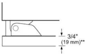
Freezer/Wine column can be installed flush or proud.
Flush – With a 25" (635 mm) cutout depth, the front face of the freezer/wine column fits flush with 25" (635 mm) depth adjacent cabinets.
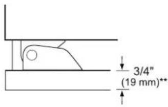
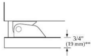
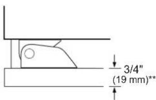
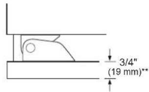
Proud – With a 24" (610 mm) depth cutout, the front face of the freezer/wine column extends approximately 3/4" (19 mm) beyond 24" (610 mm) depth adjacent cabinets.
- A minimum 4" (102 mm) finished return that matches the cabinet exterior is recommended on all sides and the top of the cutout opening. The shaded area will be visible after installation.
ELECTRICAL
A 115V, 60Hz, 15 or 20 amp power supply is required. An individual, properly grounded branch circuit or circuit breaker is recommended. Install a properly grounded 3-prong electrical receptacle recessed into the back wall. Electrical must be located on rear wall as shown.
Note: GFI (ground fault interrupter) is not recommended.
WATER LINE
A cold water supply is required for automatic icemaker operation.
The water pressure must be between 20 and 120 psi.
Tubing should be long enough to extend to the front of the freezer. Allow enough tubing to accommodate a bend leading into the water line connection.
Water line can enter an opening through the floor or back wall.
Install a shut-off valve between the icemaker water valve and the cold water supply in the home.
INSTALLATION CLEARANCES
TOP VIEW
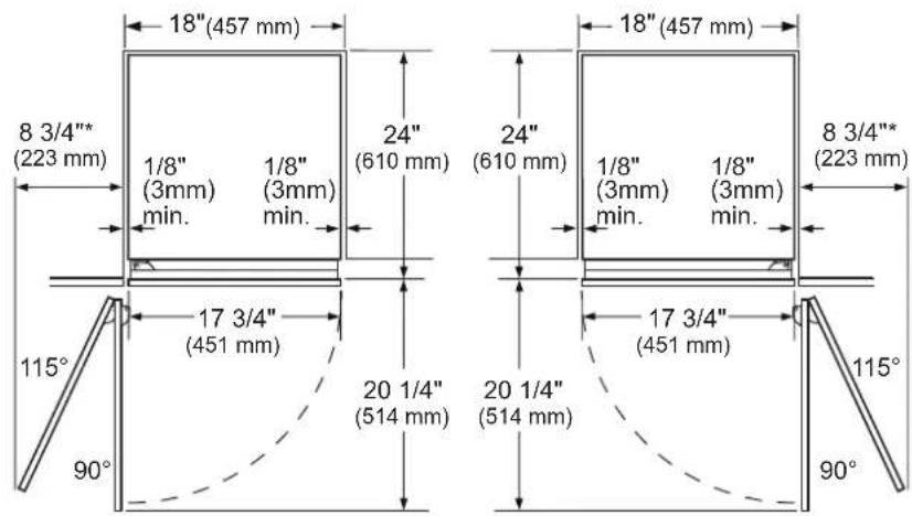
SKSCF1801P SKSCW181RP
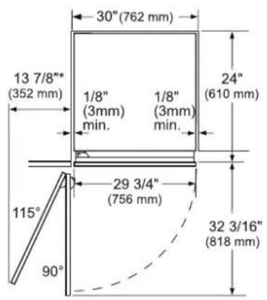
* Door handle must be added to this dimension.
**Varies depending on the thickness of the custom cabinet panel. The door panels in the optional Signature Kitchen Suite stainless steel door panel kit are 3/4" (19 mm) thick.

NOTE
Door Swing Clearances
The installation must allow for clearances to adjacent walls or cabinets. This freezer/wine column is equipped with a 2-position door stop.
The factory-set 115° door swing can be adjusted to 90° if clearance to adjacent cabinets or walls is restricted.
Door Handle Clearances
The door handle depth must be added to the dimension where noted to determine the total clearance required from adjacent cabinets or walls. This clearance will vary depending on the custom handle used. When using Signature Kitchen Suite handles or the Signature Kitchen Suite stainless steel door panel kit with handles (optional accessories), the door handle clearance with the door open 115° is 11" (279 mm).
SKSCF2401P - 24" INTEGRATED FREEZER COLUMN
SKSCR2401P - 24" INTEGRATED REFRIGERATOR COLUMN
SKSCW241RP - 24" INTEGRATED WINE COLUMN
CUTOUT DIMENSIONS – FLUSH OR PROUD INSTALLATION, SINGLE COLUMN
NOTE
Freezer/Wine / Refrigerator column can be installed flush or proud
Flush – With a 25" (635 mm) cutout depth, the front face of the freezer/wine column fits flush with 25" (635 mm) depth adjacent cabinets.
Proud – With a 24" (610 mm) depth cutout, the front face of the freezer/wine column extends approximately 3/4" (19 mm) beyond 24" (610 mm) depth adjacent cabinets.
- A minimum 4" (102 mm) finished return that matches the cabinet e terior is recommended on all sides and the top of the cutout opening. The shaded area will be visible after installation.
ELECTRICAL
A 115V, 60Hz, 15 or 20 amp power supply is required. An individual, properly grounded branch circuit or circuit breaker is recommended. Install a properly grounded 3-prong electrical receptacle recessed into the back wall. Electrical must be located on rear wall as shown.
Note: GFI (ground fault interrupter) is not recommended.
WATER LINE
A cold water supply is required for automatic icemaker operation.
The water pressure must be between 20 and 120 psi.
Tubing should be long enough to extend to the front of the freezer. Allow enough tubing to accommodate a bend leading into the water line connection.
Water line can enter an opening through the floor or back wall
Install a shut-off valve between the icemaker water valve and the cold water supply in the home.
INSTALLATION CLEARANCES
TOP VIEW
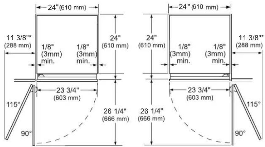
SKSCF2401P SKSCR2401P
* Door handle must be added to this dimension.
**Varies depending on the thickness of the custom cabinet panel. The door panels in the optional Signature Kitchen Suite stainless steel door panel kit are 3/4" (19 mm) thick.
SKSCW241RP
NOTE
Door Swing Clearances
- The installation must allow for clearances to adjacent walls or cabinets. The appliances are equipped with 2-position door stops.
- The factory-set 115^ door swing can be adjusted to 90^ if clearance to adjacent cabinets or walls is restricted.
Door Handle Clearances
The door handle depth must be added to the dimension where noted to determine the total clearance required from adjacent cabinets or walls. This clearance will vary depending on the custom handle used. When using Signature Kitchen Suite handles or the Signature Kitchen Suite stainless steel door panel kit with handles (optional accessories), the door handle clearance with the door open 115° is 14" (356 mm).
SKSCF3001P - 30" INTEGRATED FREEZER COLUMN
SKSCR3001P - 30" INTEGRATED REFRIGERATOR COLUMN
CUTOUT DIMENSIONS – FLUSH OR PROUD INSTALLATION, SINGLE COLUMN
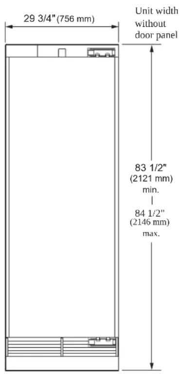
30" (762 mm)
finished width
4" (102 mm) finished return*
25"(635 mm)
min. depth
flush install
24" (610 mm)
min. depth
proud install
84"
(2134 mm)
5"
(127 mm)
electrical
location
4"
(102 mm)
water
location
1 3/8" (35mm)
Electrical location
Is Not available
1 3/8" (35mm)
Electrical location
Is Not available
NOTE
Freezer / Refrigerator can be installed flush or proud.
Flush – With a 25" (635 mm) cutout depth, the front face of the refrigerator fits flush with 25" (635 mm) depth adjacent cabinets.
Proud – With a 24" (610 mm) depth cutout, the front face of the refrigerator extends approximately 3/4" (19 mm) beyond 24" (610 mm) depth adjacent cabinets.
* A minimum 4" (102 mm) finished return that matches the cabinet exterior is recommended on all sides and the top of the cutout opening. The shaded area will be visible after installation.
ELECTRICAL
A 115V, 60Hz, 15 or 20 amp power supply is required. An individual properly grounded branch circuit or circuit breaker is recommended. Install a properly grounded 3-prong electrical receptacle recessed into the back wall. Electrical must be located on rear wall as shown.
Note: GFI (ground fault interrupter) is not recommended.
WATER LINE
The water pressure must be between 20 and 120 psi.
Tubing should be long enough to extend to the front of the refrigerator. Allow enough tubing to accommodate a bend leading into the water line connection.
Water line can enter an opening through the floor or back wall.
Install a shut-off valve between the water valve and cold water supply in the home.
INSTALLATION CLEARANCES
TOP VIEW
SKSCF3001P

SKSCR3001P
*Door handle must be added to this dimension.
**Varies depending on the thickness of the custom cabinet panel. The door panels in the optional Signature Kitchen Suite stainless steel door panel kit are 3/4" (19 mm) thick.
NOTE
Door Swing Clearances
The installation must allow for clearances to adjacent walls or cabinets. This freezer / refrigerator is equipped with a 2-position door stop. The factory-set 115° door swing can be adjusted to 90° if clearance to adjacent cabinets or walls is restricted.
Door Handle Clearances
The door handle depth must be added to the dimension where noted to determine the total clearances required from adjacent cabinets or walls. This clearance will vary depending on the custom handle used. When using Signature Kitchen Suite handles or the Signature Kitchen Suite stainless steel door panel kit with handles (optional accessories), the door handle clearance with the door open 115° is 16" (406 mm).
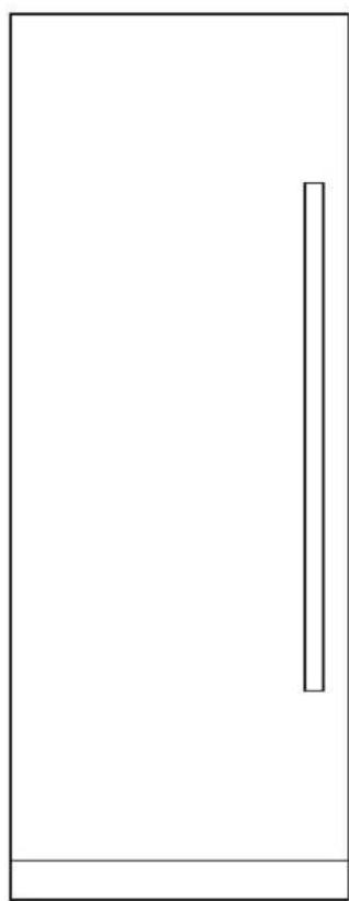
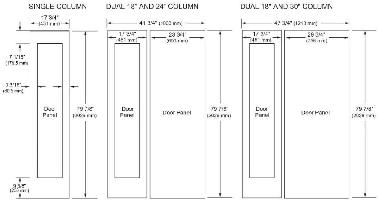
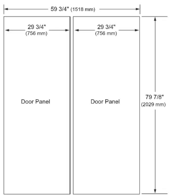
SKSCF1801P - 18" INTEGRATED FREEZER COLUMN
SKSCW181RP - 18" INTEGRATED WINE COLUMN
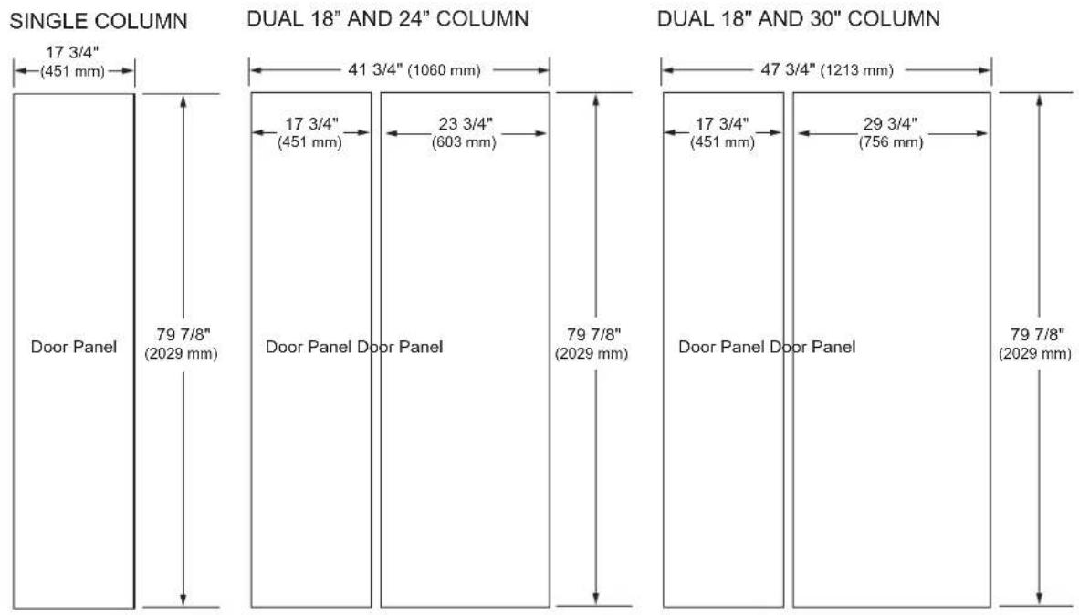
3/4" (19 MM) CUSTOM PANEL DIMENSIONS – FLUSH INSTALLATION
Freezer/Refrigerator Column
Wine Column

NOTES
Trimmed units are designed to be customized with decorative panels. Field-installed 3/4" (19 mm) custom door panels are required.
For custom panels: Use templates provided with units to pre-drill holes for mounting panel brackets (provided with unit). Adjustment screws and instructions also provided with units.
Maximum total door panel weight for 30" column is 64 lb.
Maximum total door panel weight for 24" column is 53 lb.
Maximum total door panel weight for 18" column is 44 lb.
DESIGN TIPS
4" (102 mm) will be visible on the interior sides of the cutout. It is recommended that the interior of the enclosure be finished to match the exterior. For retrofit/replacement installations, the optional frame kit may be used.
If using custom panels, a custom toe kick is required.
The bottom of the case is unfinished.
Door Handles: Handles are not included with the units.
Custom handles are required for installation. Brushed aluminum handles are available as an optional accessory.
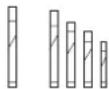
OPTIONAL ACCESSORIES – FLUSH OR PROUD INSTALLATION
SKSPK180CS/SKSPK185CS - STAINLESS STEEL PANEL KIT FOR 18" FREEZER COLUMN
SKSWK185RS/SKSWK185LS - STAINLESS STEEL PANEL KIT FOR 18" WINE COLUMN
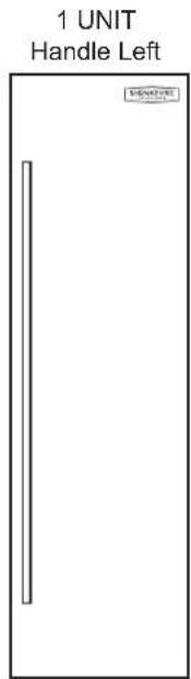
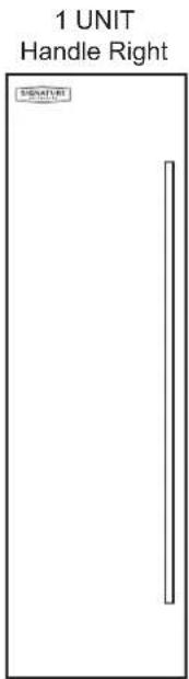
This unit can be installed with an optional stainless steel panel kit. The freezer column kit is reversible and can be used in both right hand and left hand door swing installations. The wine column panel kits are not reversible.
SKSFK800CS - FRAME KIT
This unit can be installed in a 24" (610 mm) deep cutout with an optional frame kit. The kit includes two 80" (2032 mm) brushed aluminum side trim pieces. Each trim piece is 5" (127 mm) deep with a 1/8" (3 mm) front face.
HANDLES FOR USE WITH CUSTOM PANELS
SKSHK310HS - 31 11/16" (805 mm) Medium Brushed Aluminum Handle
SKSHK480HS - 48" (1219 mm) Long Brushed Aluminum Handle
DESIGN TIPS
SKSPK180CS SKSWK185LS SKSWK185RS
SKSPK185CS
WARNING
Finishing of the handle has been chaged from glossy to matte since April, 2022. When pair-installing a product,
- Please identify the production date on the panel installation box.
- Match the production date of the handles into before April 2022 or after April 2022.
The stainless steel panel kit may be used in a flush 25" (635 mm) cutout depth installation or in a proud 24" (610 mm) cutout depth installation.
The optional frame kit is recommended for retrofit/ replacement installations where the existing cutout is 24" (610 mm) deep.
SKSCF2401P - 24" INTEGRATED FREEZER COLUMN
SKSCR2401P - 24" INTEGRATED REFRIGERATOR COLUMN
SKSCW241RP - 24" INTEGRATED WINE COLUMN
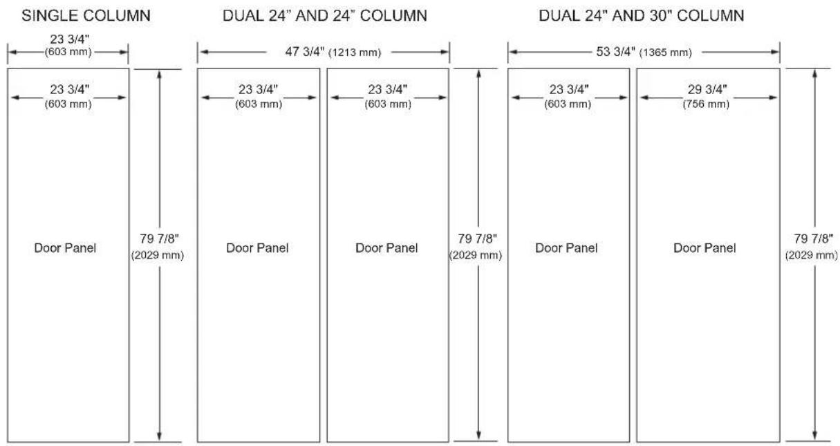
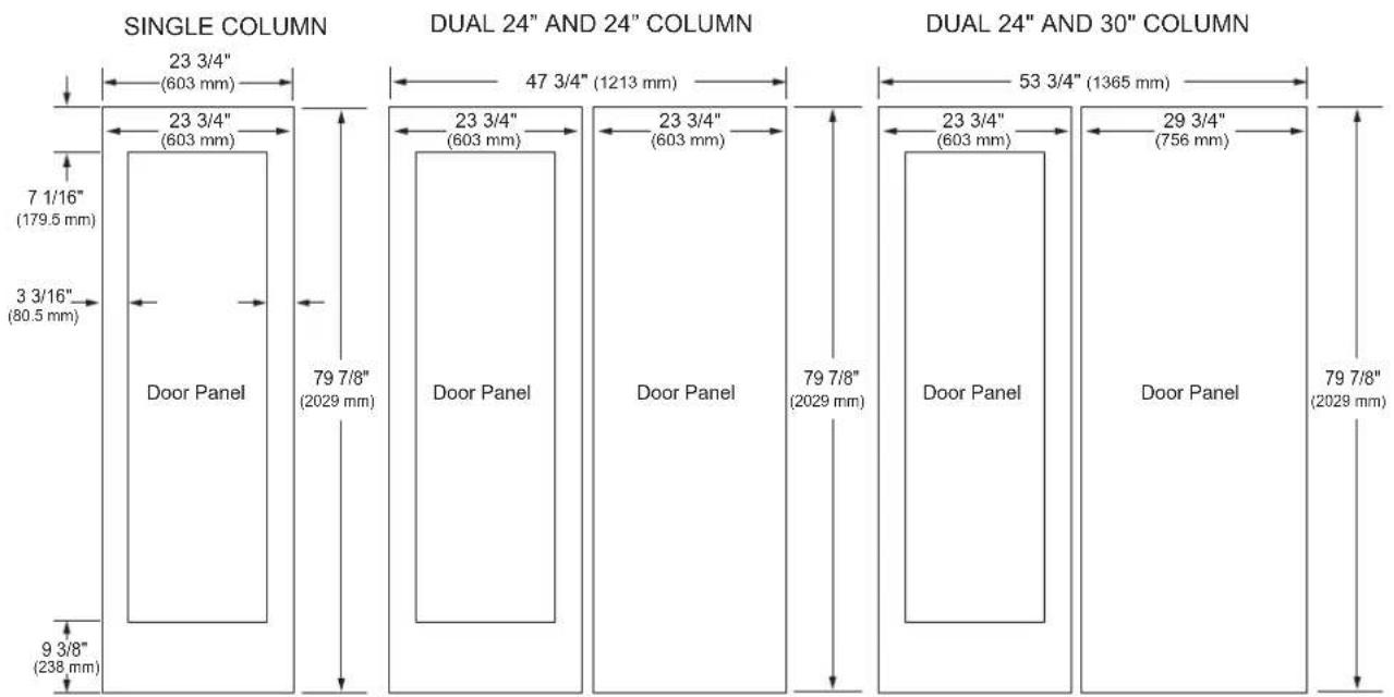
3/4" (19 MM) CUSTOM PANEL DIMENSIONS – FLUSH INSTALLATION
Freezer/Refrigerator Column
bar
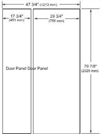
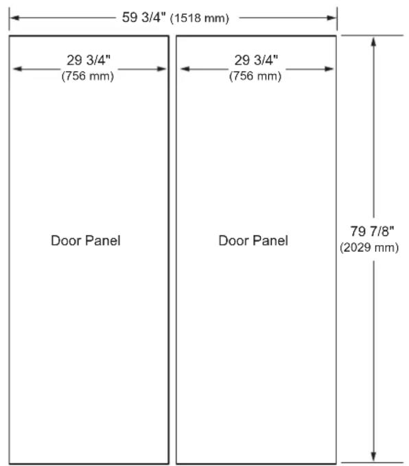
| Column Type | Section | Width (mm) | | ----------------------- | ----------------- | ---------- | | SINGLE COLUMN | 23 3/4" | 603 | | SINGLE COLUMN | Door Panel | 79 7/8" | | DUAL 24" AND 24" COLUMN | 47 3/4" | 1213 | | DUAL 24" AND 24" COLUMN | Door Panel | 603 | | DUAL 24" AND 24" COLUMN | Door Panel | 79 7/8" | | DUAL 24" AND 30" COLUMN | 53 3/4" | 1365 | | DUAL 24" AND 30" COLUMN | Door Panel | 603 | | DUAL 24" AND 30" COLUMN | Door Panel | 756 | | DUAL 24" AND 30" COLUMN | Door Panel | 29 3/4" | | DUAL 24" AND 30" COLUMN | Door Panel | 2029 |Wine Column
bar
| Column Type | Total Height (mm) | Base Height (mm) | |-------------|-------------------|------------------| | Single Column | 23 3/4" (603 mm) | 7 1/16" (179.5 mm) | | Single Column | 23 3/4" (603 mm) | 3 3/16" (80.5 mm) | | Single Column | Door Panel | 9 3/8" (238 mm) | | Dual 24" AND 24" COLUMN | 47 3/4" (1213 mm) | 79 7/8" (2029 mm) | | Dual 24" AND 24" COLUMN | 23 3/4" (603 mm) | 79 7/8" (2029 mm) | | Dual 24" AND 24" COLUMN | Door Panel | 23 3/4" (603 mm) | | Dual 24" AND 24" COLUMN | Door Panel | 29 3/4" (756 mm) | | Dual 24" AND 24" COLUMN | Door Panel | 79 7/8" (2029 mm) | | Dual 24" AND 30" COLUMN | 53 3/4" (1365 mm) | — | | Dual 24" AND 30" COLUMN | — | — | | Dual 24" AND 30" COLUMN | — | — | | Dual 24" AND 30" COLUMN | — | — | | Dual 24" AND 30" COLUMN | — | — | | Dual 24" AND 30" COLUMN | — | — | | Dual 24" AND 30" COLUMN | — | — | | Dual 24" AND 30"COLUMN | — | — | | Dual 24" AND 30"COLUMN | — | — | | Dual 24" AND 30"COLUMN | — | — | | Dual 24" AND 30"COLUMN | — | — | | Dual 24" AND 30"COLUMN | — | — | | Dual 24" AND 30"COLUMN | — | — | | Dual 24" AND 31" COLUMN | — | — | | Dual 24" AND 31" COLUMN | — | — | | Dual 24" AND 31" COLUMN | Door Panel | Door Panel | | Dual 24" AND 31" COLUMN | Door Panel | Door Panel | | Dual 24" AND 31" COLUMN | Door Panel | Door Panel | | Dual 24" AND 31" COLUMN | Door Panel | Door Panel | | Dual 24" AND 31" COLUMN | Door Panel | Door Panel | | Dual 24" AND 31" COLUMN | Door Panel | Door Panel | | Dual 16 Column | — | — | | Dual 16 Column | — | — | | Dual 16 Column | — | — | | Dual 16 Column | Door Panel | Door Panel | | Dual 16 Column | Door Panel | Door Panel | | Dual 16 Column | Door Panel | Door Panel | | Dual 16 Column | Door Panel | Door Panel | | Dual 16 Column | Door Panel | Door Panel | | Dual 16 Column | Door Panel | Door Panel | | Dual 16 Column | Door Panel | Door Panel | | Dual 16 Column | Door Panel | Door Panel | | Dual 16 Column | — | — | | Dual 16 Column | — | — | | Dual 16 Column | — | — | | Dual 16 Column | — | — | | Dual 16 Column | — | — | | Dual 16 Column | — | — | | Dual 16 Column | — | — | | Dual 16 Column | — | — | | Dual 16 Column | — | — | | Dual 16 Column | — | — |NOTES
Trimmed units are designed to be customized with decorative panels. Field-installed 3/4" (19 mm) custom door panels are required.
For custom panels: Use templates provided with units to pre-drill holes for mounting panel brackets (provided with unit). Adjustment screws and instructions also provided with units.
Maximum total door panel weight for 30" column is 64 lb.
Maximum total door panel weight for 24" column is 53 lb.
Maximum total door panel weight for 18" column is 44 lb.
DESIGN TIPS
4" (102 mm) will be visible on the interior sides of the cutout. It is recommended that the interior of the enclosure be finished to match the exterior. For retrofit/replacement installations, the optional frame kit may be used.
If using custom panels, a custom toe kick is required.
The bottom of the case is unfinished.
Door Handles: Handles are not included with the units.
Custom handles are required for installation. Brushed aluminum handles are available as an optional accessory.
OPTIONAL ACCESSORIES – FLUSH OR PROUD INSTALLATION
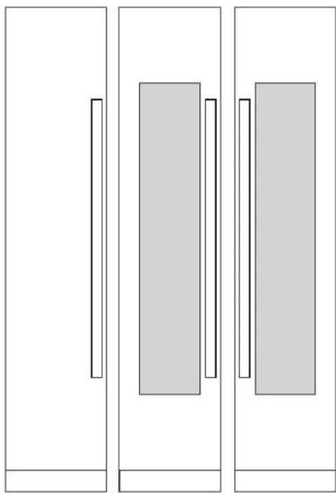
natural_image
Three vertical panels with rectangular cutouts, no text or symbols presentSKSPK240CS
SKSWK245LS SKSWK245RS
SKSPK245CS

WARNING
Finishing of the handle has been chaged from glossy to matte since April, 2022. When pair-installing a product,
- Please identify the production date on the panel installation box.
- Match the production date of the handles into before April 2022 or after April 2022.
SKSPK240CS/SKSPK245CS - STAINLESS STEEL PANEL KIT FOR 24" FREEZER / REFRIGERATOR COLUMN SKSWK245RS/SKSWK245LS - STAINLESS STEEL PANEL KIT FOR 24" WINE COLUMN
This unit can be installed with an optional stainless steel panel kit. The freezer/refrigerator column kit is reversible and can be used in both right hand and left hand door swing installations. The wine column panel kits are not reversible.
SKSFK800CS - FRAME KIT
This unit can be installed in a 24" (610 mm) deep cutout with an optional frame kit. The kit includes two 80" (2032 mm) brushed aluminum side trim pieces. Each trim piece is 5" (127 mm) deep with a 1/8" (3 mm) front face.
HANDLES FOR USE WITH CUSTOM PANELS
SKSHK310HS - 31 11/16" (805 mm) Medium Brushed Aluminum Handle
SKSHK480HS - 48" (1219 mm) Long Brushed Aluminum Handle
DESIGN TIPS
The stainless steel panel kit may be used in a flush 25" (635 mm) cutout depth installation or in a proud 24" (610 mm) cutout depth installation.
The optional frame kit is recommended for retrofit/ replacement installations where the existing cutout is 24" (610 mm) deep.
SKSCF3001P - 30" INTEGRATED FREEZER COLUMN
SKSCR3001P - 30" INTEGRATED REFRIGERATOR COLUMN
3/4" (19 MM) CUSTOM PANEL DIMENSIONS – FLUSH INSTALLATION
SINGLE COLUMN
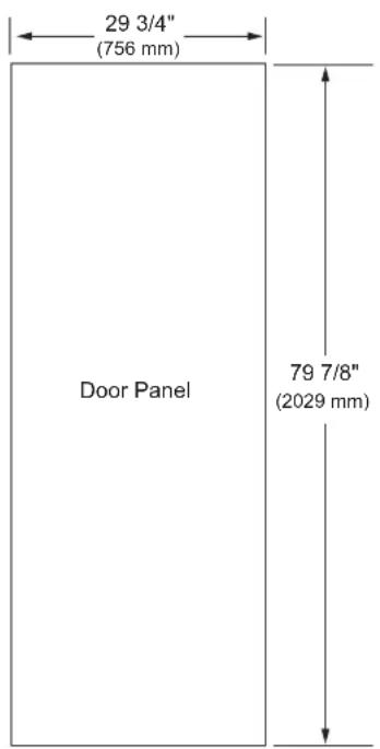
DUAL 30" AND 30" COLUMN

NOTES
Trimmed units are designed to be customized with decorative panels. Field-installed 3/4" (19 mm) custom door panels are required.
For custom panels: Use templates provided with units to pre-drill holes for mounting panel brackets (provided with unit). Adjustment screws and instructions also provided with units.
Maximum total door panel weight for 30" column is 64 lb.
Maximum total door panel weight for 24" column is 53 lb.
Maximum total door panel weight for 18" column is 44 lb.
DESIGN TIPS
4" (102 mm) will be visible on the interior sides of the cutout. It is recommended that the interior of the enclosure be finished to match the exterior. For retrofit/replacement installations, the optional frame kit may be used.
If using custom panels, a custom toe kick is required. The bottom of the case is unfinished.
Door Handles: Handles are not included with the units. Custom handles are required for installation. Brushed aluminum handles are available as an optional accessory.
OPTIONAL ACCESSORIES – FLUSH OR PROUD INSTALLATION
natural_image
Simple line drawing of a door with a vertical bar on the left side (no text or symbols)SKSPK300CS SKSPK305CS
SKSPK300CS/SKSPK305CS - STAINLESS STEEL PANEL KIT FOR 30" FREEZER / REFRIGERATOR COLUMN
This unit can be installed with an optional stainless steel panel kit. The kit includes one door panel, one toe kick and one handle. This kit is reversible and can be used in both right hand and left hand door swing installations.
SKSFK800CS - FRAME KIT
This unit can be installed in a 24" (610 mm) deep cutout with an optional frame kit. The kit includes two 80" (2032 mm) brushed aluminum side trim pieces. Each trim piece is 5" (127 mm) deep with a 1/8" (3 mm) front face.
HANDLES FOR USE WITH CUSTOM PANELS
SKSHK310HS - 31 11/16" (805 mm) Medium Brushed Aluminum Handle
SKSHK480HS - 48" (1219 mm) Long Brushed Aluminum Handle DESIGN TIPS
The stainless steel panel kit may be used in a flush 25" (635 mm) cutout depth installation or in a proud 24" (610 mm) cutout depth installation.
The optional frame kit is recommended for retrofit/replacement installations where the existing cutout is 24" (610 mm) deep.

WARNING
Finishing of the handle has been chaged from glossy to matte since April, 2022. When pair-installing a product,
- Please identify the production date on the panel installation box.
- Match the production date of the handles into before April 2022 or after April 2022.
Required Accessories and Tools
Supplied Accessories
- Installation instructions
- Operating instructions
- Installation kit
• Water filter (included with refrigerator)
Other
- Stepladder
• Dolly, hand truck - Hammer drill for drilling holes in wall or floor.
- Drill bits in various sizes and suitable for materials
- Wood screws in different sizes
- Thin plywood sheet, particle board or cardboard to protect the floor from damage
- Suitable material for covering and protecting furniture (e.g. protective sheets)
- Adhesive tape
- An additional unification kit is available as an accessory (part number SKSFJ800P) from Signature Kitchen Suite.
Tools
 | Cordiess screwdriver |
 | Torx bit T20, T30 and magnetic holder |
 | Torx screwdriver T20, T30 |
 | 6/16"(10 mm) hex nut driver |
 | Various drill bits |
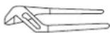 | Multigrip pliers |
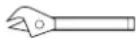 | Adjustable wrench |
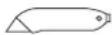 | Cutter with adjustable blade |
 | Metal tape measure, folding rule |
 | Square |
 | Level, length 2" (60 cm) and 4'(1.2 m) |
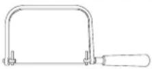 | saw to cut top trim pieces (for retrofit installation only) |
Installation
The following installation instructions describe the installation steps for various appliance types:
• Refrigerator units with water dispenser
• Freezer units with ice maker
The diagrams may be a general representation of your appliance.
Particular reference is made to special installation steps for individual appliance types.
Unpacking

WARNING
To avoid serious injury or product damage:
- DO NOT open appliance door unless the product is secured against tipping.
- The appliance is very heavy and is prone to tipping if not secured.
- To avoid injury, use 2 or more people and proper lifting techniques when lifting or moving the appliance.
Check appliance for damage in transit.
Do not install the appliance if it is visibly damaged.
If in doubt, contact your dealer.
- Remove the packaging carton, being careful not to damage the surface of the appliance.
- To avoid floor damage, place packaging cardboard or plywood under the appliance.
- Remove accessories on the sides and underneath the appliance.
NOTE:
To avoid damaging parts, do not remove the protective shipping materials inside the appliance until the installation is complete.
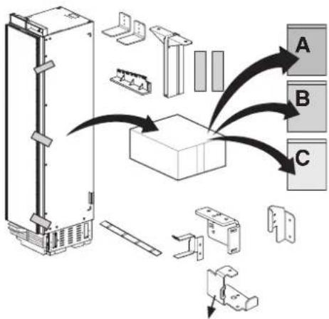
4. Installation Preparation
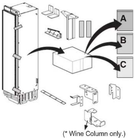
Unpack installation materials and accessories.
To simplify installation, the packages are identified with labels A, B and C corresponding to the manual sections.
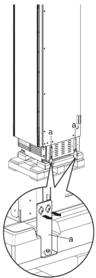
CAUTION:
Appliance is very heavy. Use two or more people when lifting or moving the appliance.
- Remove shipping brackets (a) and lift the appliance off the pallet.
Moving the Appliance

WARNING
• To avoid injury, use 2 or more people and observe proper lifting techniques when lifting or moving the appliance.
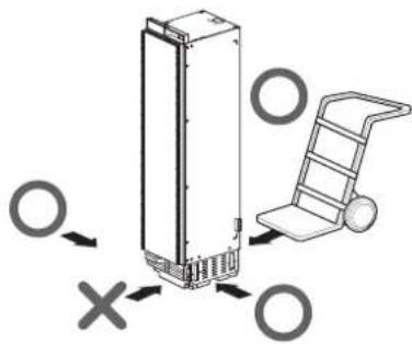
- If the appliance cannot be transported in an upright position, transport it horizontally.
To avoid product damage:
- Do not tilt the appliance toward the sides or lay it on its sides.
• Make sure there is sufficient room to stand the appliance upright before doing so. - Use a dolly, lift truck or hand cart to transport the appliance.
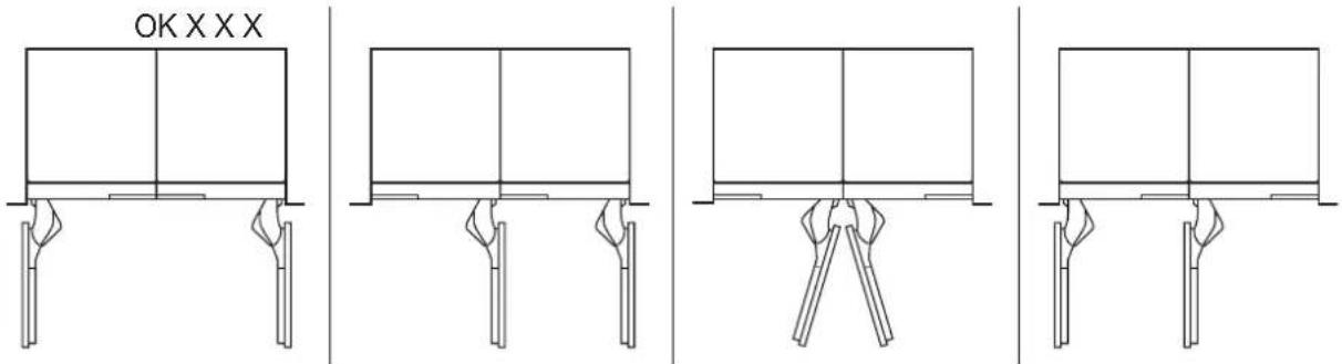
- Transport from the rear side of the appliance ONLY.
- Secure the appliance during transport to prevent it from tipping.
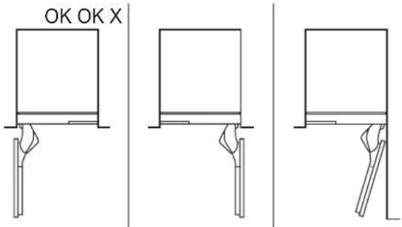
| Raise up via appliance rear | Do not raise up from appliance side |
 | 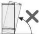 |
Special Circumstances
Before proceeding with your installation, check if any of the following special circumstances apply to your installation. If so, follow the relevant instructions in the Special Installations section before continuing the installation.
- Retrofit installation in existing enclosure: see Optional Frame Kit Accessory section.
- Reversing door swing: see Door Reversal section.
- Side-by-Side installation of 2 appliances: see Side-by-Side Installation section.
Product Dimensions
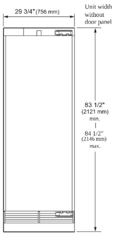
18" Freezer / Wine Column
FRONT VIEW

TOP VIEW
DOOR OPEN 90°

TOP VIEW
DOOR OPEN 115°
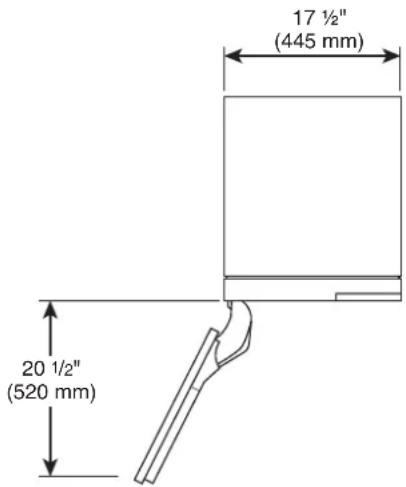
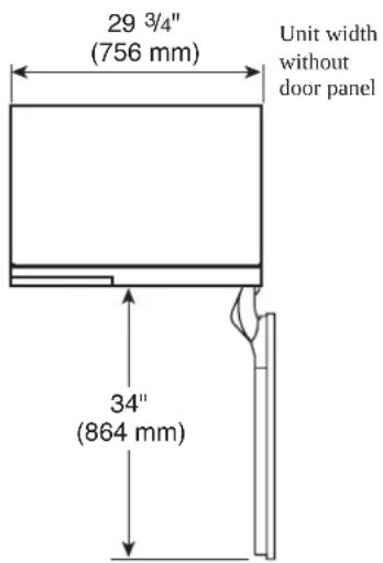
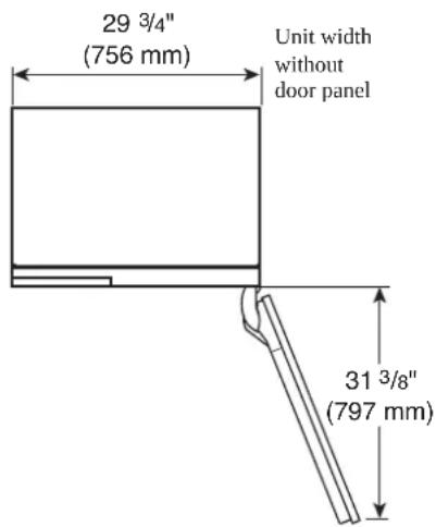
Unit width without door panel
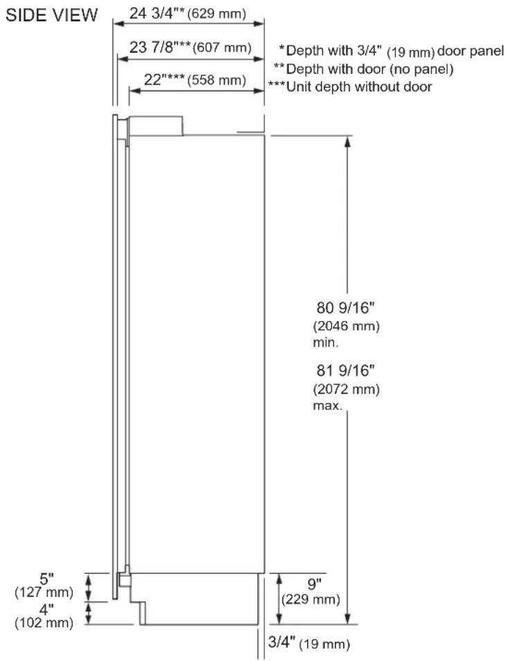
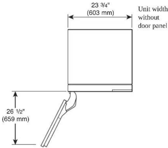
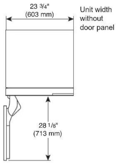
24" Freezer / Refrigerator / Wine Column
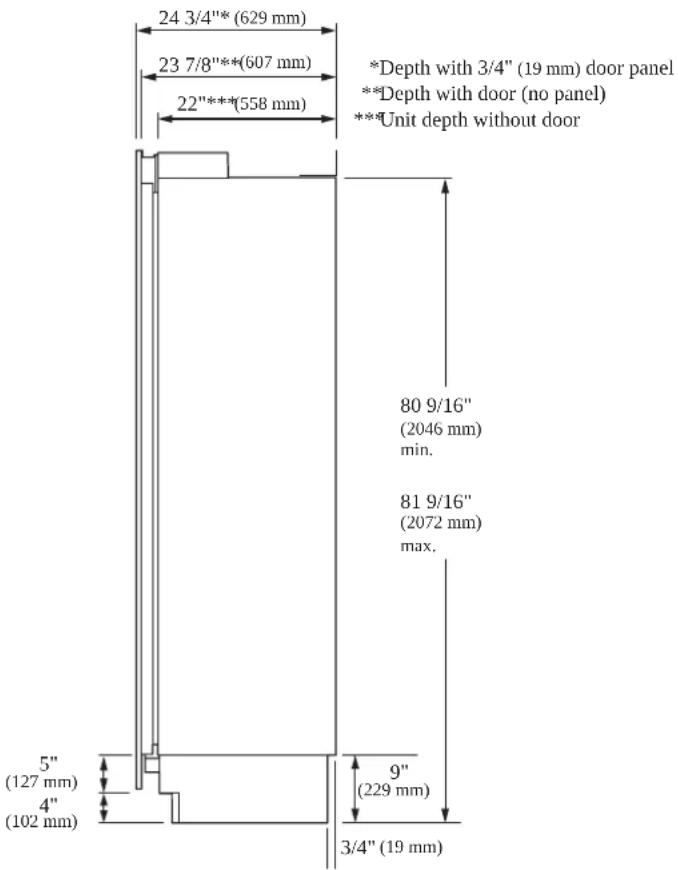
| FRONT VIEW | SIDE VIEW | 24 3/4"*(629 mm) | ||
| 23 3/4"(603 mm) | Unit width without door panel | 23 7/8"***(607 mm) | * Depth with 3/4" (19 mm) door panel** Depth with door (no panel)*** Unit depth without door | |
| 22"***(558 mm) | ||||
83 1/2"
(2121 mm)
min.
84 1/2"
(2146 mm)
max.
80 9/16"
(2046 mm)
min.
81 9/16"
(2072 mm)
max.
5"
(127 mm)
4"
(102 mm)
9"
(229 mm)
3/4" (19 mm)
TOP VIEW
DOOR OPEN 90°
23 3/4"
(603 mm)
Unit width
without
door panel
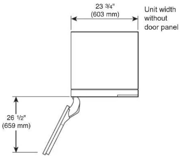
TOP VIEW
DOOR OPEN 115°
23 3/4"
(603 mm)
Unit width
without
door panel
28 1/8"
(713 mm)
26 1/2"
(659 mm)
30" Freezer / Refrigerator Column
FRONT VIEW
SIDE VIEW
TOP VIEW
DOOR OPEN 90°

TOP VIEW
DOOR OPEN 115°

A
Installing the Anti-tip Brackets

WARNING
To avoid injury or damage, check for electrical wires or plumbing in walls before drilling or installing screws.

CAUTION
To avoid injury, observe all safety practices during installation, including wearing safety glasses and other safety apparel.
ENGLISH
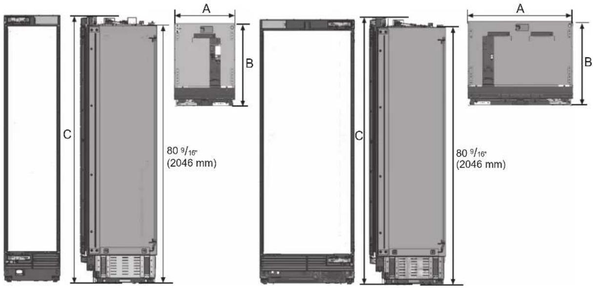
| 18" Unit 24" Unit 30" Unit | ||
| A (Width) 17 1⁄2" (445 mm) 23 3/4" (603 mm) 29 3/4" (756 mm) | ||
| B (Depth) 23 7/8"(607 mm) | ||
| C (Height) 83 1⁄2"(2121 mm) | ||
| D (Back height) 80 9/16"(2046 mm) | ||
NOTE:
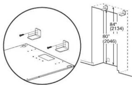
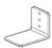
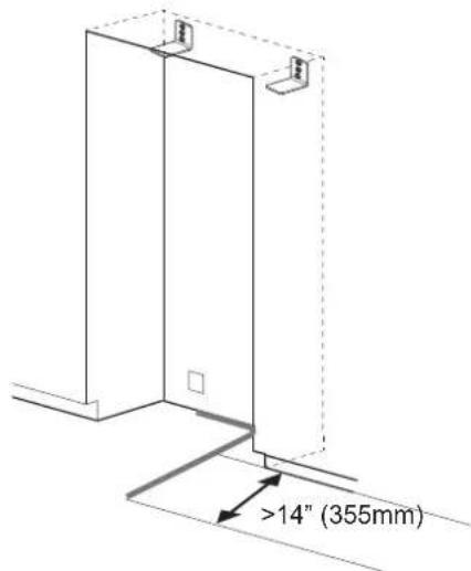
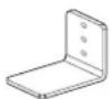
2 anti-tip-brackets are required for each appliance.
The anti-tip-brackets must overlap a minimum of 2 1/8" (54 mm) over the appliance to secure the appliance.
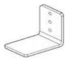
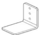
Anti-tip brackets (2)
- Install the anti-tip brackets at the rear of the enclosure, locating the brackets based on stud locations and product and enclosure dimensions.
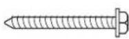
Concrete / Wood wall
5X45 6X (Hex)
- Make sure the anti-tip brackets are securely attached to a stud or other weight-bearing structure. Do not attach brackets to drywall, cinder block, or uncured concrete.
To ensure safety, at least one bracket must be attached to a stud. Attach brackets to studs wherever possible within the enclosure. Use a minimum of 3 screws or bolts to attach each bracket.
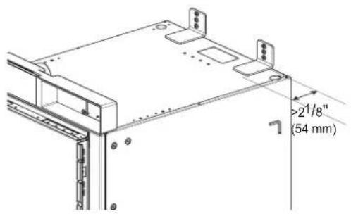
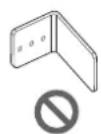
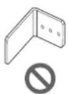
Brackets must be attached as shown at right. The brackets could fail to prevent tipover of the unit if installed in an alternate orientation.


(no text)
(no text)
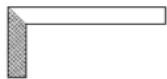
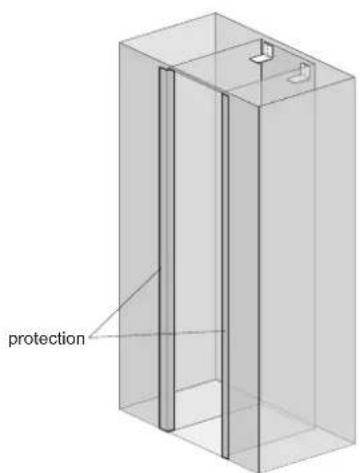
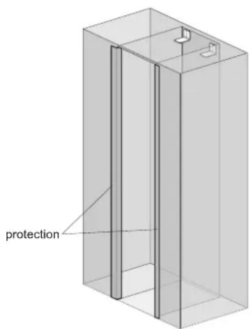
Protecting Edges of Enclosure
To protect the front edges of the enclosure, tape thin cardboard or some other protective material around the edges.
Installing Appliance in Enclosure

WARNING
Use 2 or more people when installing the appliance. Take care when moving the appliance. It is very heavy and prone to tipping when not secured.

CAUTION
Take care to avoid damaging the water line or power cord when moving the appliance into the enclosure.
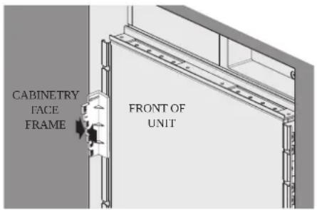
Before moving the unit into position, secure the door/ drawers closed and protect any finished flooring.
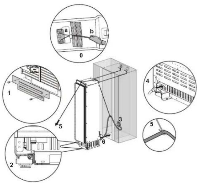
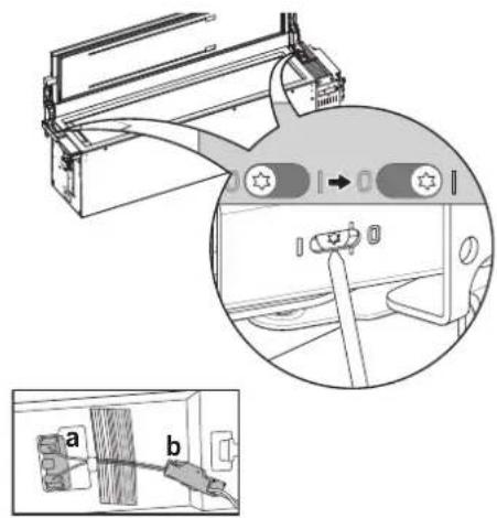
Before moving the unit into position, make sure that the door switch is positioned correctly according to the guide structure(a), and the connector housing is connected completely(b).
Use an appliance dolly to move the unit near the opening.
The front leveling legs are extended below the front rollers to improve stability during placement. Once the unit is placed in front of the opening, completely retract the front leveling legs to allow the unit to be rolled into position. Front and rear leveling legs can be adjusted from the front once the unit is positioned.
If the unit has been on its back or side, it must stand upright for a minimum of 24 hours before turning on the power.
After the appliance is rolled into position, verify that the anti-tip brackets are properly engaged.
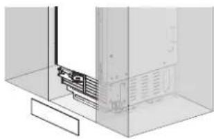
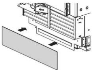
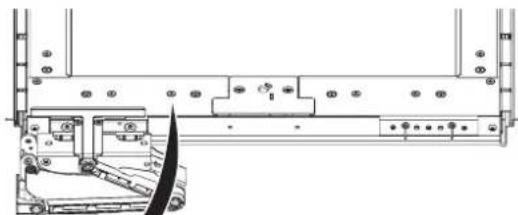
- Remove the base panel.
- Retract the leveling legs so the appliance can be wheeled forward.
- Plug the power cord into the outlet.
- Push the water line through the hole at the rear of the appliance until it emerges from the hole at the front of the appliance.
- Tie a long string around the middle of the power cord. Feed the string over the top of the appliance, pull it until the power cord is held high off the ground, then tape the string to the front of the appliance to hold the power cord off the ground. Do not pinch or strain the power cord. Make sure it is still plugged in.
- Carefully move the appliance into the enclosure, making sure not to pinch the power cord or water line under or behind the appliance.
- Remove the edge protection on the enclosure.
B
Aligning and Leveling the Appliance
DEPTH ADJUSTMENT
Adjust the depth of the unit in the enclosure so the door panels will fit flush with the surrounding cabinetry. Use the gauge tool provided for a precise fit.
1. Measure the thickness of your decorative door panels using the gauge tool.
Set the door panel on a flat, protected surface and place the gauge tool next to the panel. Mark the notch on the gauge tool that matches the thickness of the door panel.
2. Use the mark on the gauge tool to adjust the depth of the appliance in the enclosure.
Place the gauge tool against the closed door of the appliance at the side of the enclosure. The marked notch on the gauge tool should align with the front edge of the enclosure.
3. Adjust the product so that the top side is tilted 3mm to the rear compared to the lower side.
The lower side should match the 34 scale and the top side should match the 7/8 scale.
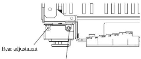
HEIGHT ADJUSTMENT
The front and rear leveling legs can both be adjusted from the front.
Front: Use 5/16" (8 mm) Phillips driver with flexible shaft.
Rear: Use 5/16" (8 mm) Phillips driver with flexible shaft.
natural_image
Isometric line drawing of a structural support frame with no text or symbolsGauge tool
Measure panel thickness
Align depth of unit
Front adjustment
WARNING
To reduce the possibility of the unit tipping forward, the front leveling legs must be in contact with the floor.
LEVELING
Once the appliance is aligned properly in the enclosure, level it using the front and rear leveling legs.
- Use a Phillips screwdriver to extend the front and rear leveling legs until they are in firm contact with the floor.

flowchart
graph TD
    subgraph Left
        A1["Raise Product"] --> B1["Rear"]
        B1 --> C1["Front"]
        C1 --> D1["Raise Product"]
    end
    subgraph Right
        E1["Raise Product"] --> F1["Rear"]
        F1 --> G1["Front"]
        G1 --> H1["Raise Product"]
    end
Leveling
-
Turn the screws as shown above to raise the appliance. Turn the screws in the opposite direction to lower the appliance.
-
Make sure the weight of the refrigerator is carried on the legs, not the wheels.
-
Use a smartphone leveling app or place a carpenter's level on the top and sides of the appliance to check that it is level and plumb. Or use the provided gauge tool to measure the distance of the bottom edge of the appliance from the floor at the front corners.
CAUTION
- If using a power drill, use the lowest torque setting.
- Leave at least 3/8 inch (10 mm) between the top front of the appliance and the top of the enclosure to fit the top filler strip.
- Do not exceed 20 inch-pounds (2.25Nm) of torque.
- 20 revolutions equal 1/16"(2mm) of height adjustment.
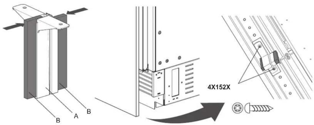
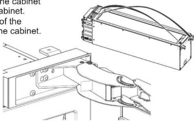
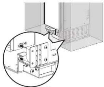
Attaching Appliance to Enclosure

WARNING
- To avoid tipovers, the appliance must be attached to the top of the enclosure.
-
The top of the enclosure must be made of a solid material (not MDF) that is at least 5/8" (16 mm) thick.
-
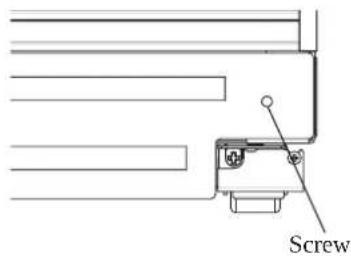
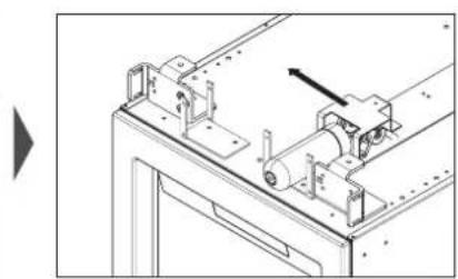
Screw the lugs on the safety bracket at the top of the appliance to the top of the enclosure.
-
If there is a large gap between the top of the appliance and the top of the enclosure, insert a piece of wood between the lugs and the top of the enclosure to fill the gap.
-
Screw the side safety brackets to the sides of the enclosure.
NOTE: If installing two appliances side-by-side, attach the appliances to each other using the unification kit. Attach them to the sides of the enclosure as if they were one unit.
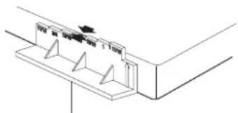
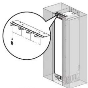
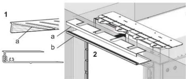
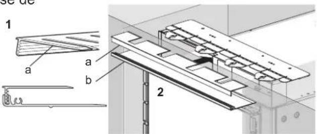
- Slide the top piece from the front filler assembly (a) in at the top of the appliance until it engages with the top safety bracket.
- Once the top piece of the filler assembly is in place, slide the base of the filler assembly in under it and snap the top into the base (b).
NOTE: If installing two appliances side-by-side, attach both top covers using the bolt found in the accessories package.
natural_image
Technical diagram of a structural assembly with an inset showing a magnified detail of a component (no text or symbols present)
4X15 4X

natural_image
Technical diagram showing a mechanical assembly with a magnified inset view (no text or symbols)
4X15 4X
natural_image
Diagram of a refrigerator with an arrow indicating rotation or movement, showing no text or symbols.
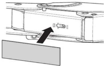
Attaching the Toe Kick Panel

CAUTION
To avoid damage to the appliance, do not block the ventilation slots in the base panel.
Stainless Toe Kick Panel (Optional Accessory)
- Screw the base panel to the appliance.
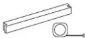
- Remove the protective film from the adhesive on the provided magnetic strips.
- Stick the magnetic strips to the back of the stainless toe kick panel.
- Attach the stainless toe kick panel to the base panel using the magnetic strips.
natural_image
Pure technical diagram showing a mechanical component inside a transparent enclosure (no text or symbols)HS179N3

Wood Toe Kick Panel
- If necessary, trim wood panel to fit width of enclosure.
- Screw the base panel to the appliance.
- Remove the protective film from the adhesive on the provided magnetic strips.
- Stick the magnetic strips to the back of the wood toe kick panel.
- Attach the wood toe kick panel to the base panel using the magnetic strips.
natural_image
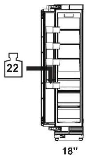
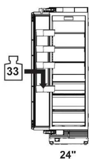
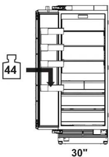
Technical diagram of a mechanical assembly with no visible text or symbolsLoading the Appliance Door
For precise results, before attaching the door panels, load the door bins with weights to ensure the gap width remains correct after food is stored in the door.
Recommendations:
• 18" Appliance: 22 lbs/10 kg
• 24" Appliance: 33 lbs/15 kg
• 30" Appliance: 44 lbs/20 kg
C
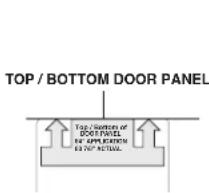
Installing Door Panels
Typical panel dimensions are based on an 84" (213.4 cm) finished height with 1/8" (3.2 mm) reveals. Template placement must be adjusted for panels exceeding typical dimensions.
The door panel should be installed first, followed by the upper then lower drawer panel, if needed.
- Place the door panel face down on a protected surface.
- Locate the correct side of the door panel template for your product and position the template flush with the top and left sides of the panel.
- Use the template to mark the correct screw locations on the back of the panel.
- Slide the template to the right so it is flush with the top and right sides of the panel.
- Use the template to mark the correct screw locations on the back of the panel.
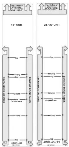
- On refrigerator/freezer columns, begin inserting a #8 x 1/2" screw into the fifth hole from the top on each side. On wine columns, use the third hole from the top. Stop when the screws are 3/16" (4 mm) proud of the panel. These will be the support screws during the panel installation.
- Insert the support screws in the slotted holes on the appliance door mounting brackets so that the panel is hanging on the door.

4X12
Mounting door panel

CAUTION
Beware of pinch points when installing door panels or opening and closing doors.
Adjusting Door Panels
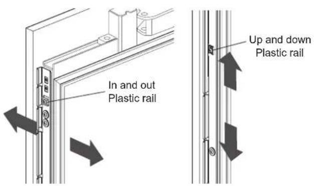
Fine adjustments can now be made to align the door panels.
- To adjust the door panel horizontally, slide the panel support screws left or right in the slotted holes as desired. Have an assistant hold the panel in place while you tighten the support screws and insert and tighten all remaining mounting screws.
- To adjust the door panel vertically or back and forward, loosen the screws in the appliance door bracket. Move the plastic rails to make adjustments as desired. Have an assistant hold the bracket in place while you tighten all the bracket screws.
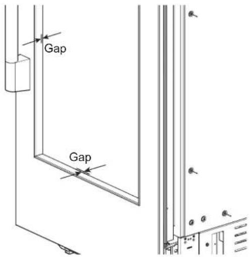
NOTES
When adjusting the wine door panel, there will be a small gap between the surface of the glass door and the plastic panel flange. This is normal.
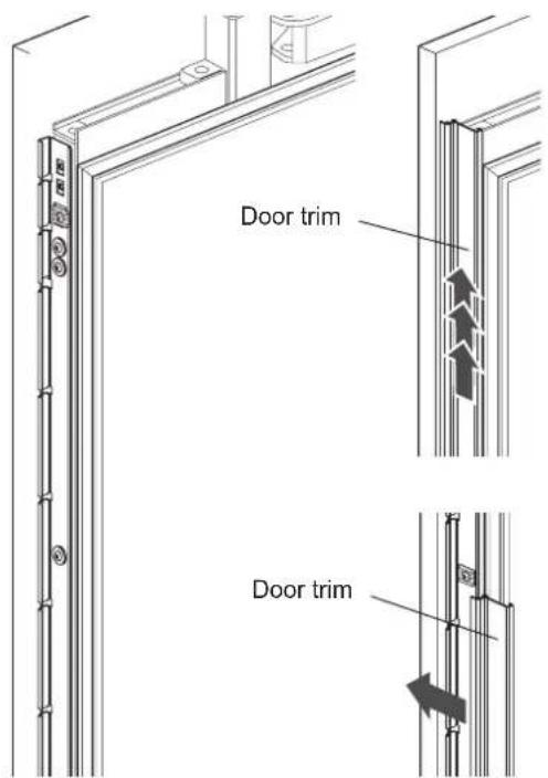
Installing Door Trim
After panels have been adjusted, install the decorative side trim on the doors. To install, start at the middle and align the trim with the front and rear flanges on the bracket, then snap into place by pushing the trim toward the back of the panel. Once the middle is secure, continue the installation upward until the remaining trim is completely secure.
Attaching Air Separator
Assemble A with B and attach on bottom front center of door.
Special Installations
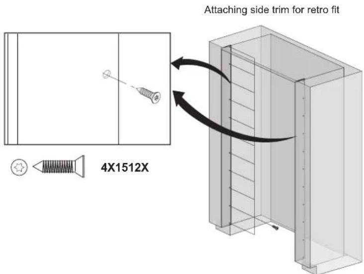
Optional Frame Kit Accessory
Purchase and install the optional frame kit for retrofit side-by-side installations. The kit includes stainless trim pieces to cover the front edges inside the enclosure. See detailed installation instructions with the kit.
Adjusting the Door Spring
Rotate the adjusting screw with the T20 bit provided.
I = maximum spring tension
0 = no spring tension
(Optional) After adjusting the door spring, attach the gray plastic sheets to hide the adjusting screws.
natural_image
Mechanical component diagram showing a bracket with a directional arrow pointing to a component (no text or symbols present)
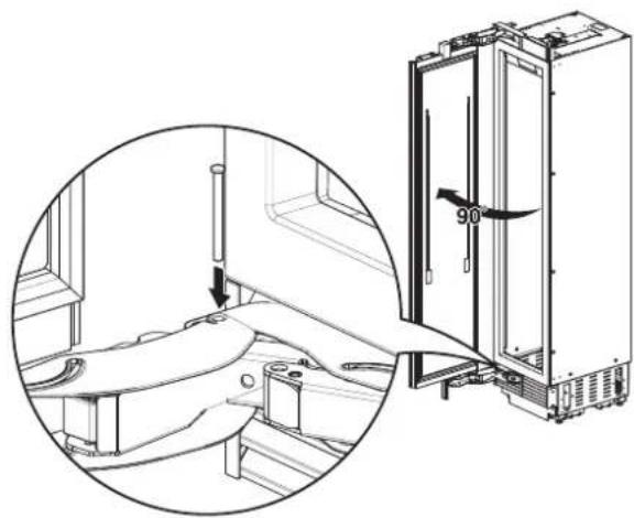
Adjusting the Door Stop
The default door stop position is 115^ . Follow these instructions to change the door stop position to 90^ .
- Open the door to 90°.
- Insert the door stop pin in the holes which are now aligned at the back of the hinge. Use a rubber mallet to fully insert the pin.
natural_image
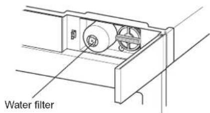
Technical line drawing of a refrigerator interior with a close-up inset showing the exterior panel and door (no text or symbols)Water Filter Bypass
Removing the water filter automatically puts the appliance in the filter bypass mode. This allows the appliance to be run without a water filter.
Removing the Water Filter
- Push in slightly on the water filter access door to open it.
- Use the cap to rotate the water filter counterclockwise and pull out the water filter. See the owner's manual for detailed instructions.
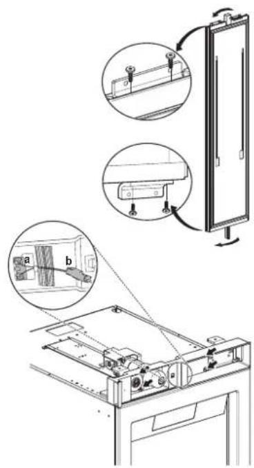
Reversing the Door

WARNING
Risk of Injury
Before working on the hinge, release the tension on the hinge spring.
NOTE:
• To make door reversal easier, place the refrigerator on its back on a flat, protected surface before beginning.
- If reversing the door with the product standing upright, the door MUST be supported while removing or installing mounting bolts.
- Open the door and release the tension on the hinge spring by using the T20 bit provided to turn the screw from | to O.
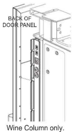
2a. (For wine columns only) Remove the 2 screws from the PCB cover (1) at the bottom of the appliance and pull off the cover. Remove the vent cover assembly as shown in step 6. Remove the 4 mounting screws from the link (2). Move the link to allow the door to be removed.
2b. If an air separator is attached, remove it. Remove the 2 mounting bolts at the top and bottom of the door (1). Remove the door (2) and lay it aside on a protected surface. - On the cabinet, remove 2 screws from the top and bottom hinges, remove the hinges, and lay the parts aside.
- Open the water filter access door. Separate the reed switch connector(b). Unscrew the 4 screws(1) and remove the front cover assembly(2).
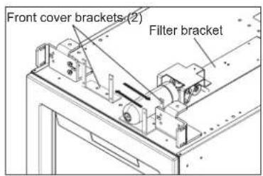
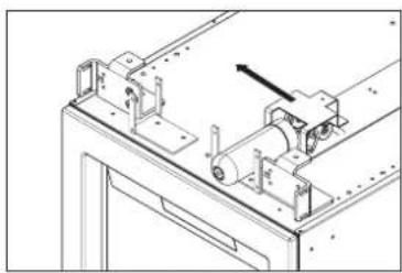
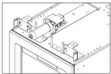
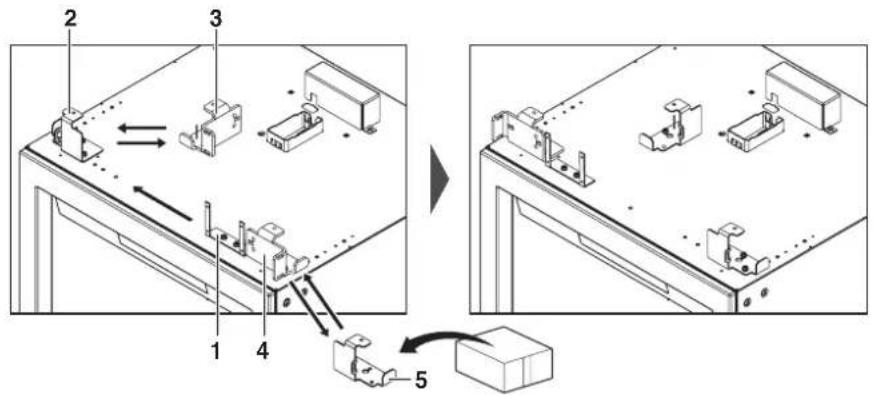
5a. (For refrigerator/freezer columns only) Remove the bolts in the 2 front cover brackets on the top of the appliance. Swap the positions of the 2 brackets, rotating one 180 degrees, and reinstall the bolts. Remove the bolts in the filter bracket and reinstall the bracket assembly on the opposite side.

natural_image
Technical line drawing of a mechanical assembly with no visible text or symbols
natural_image
Technical line drawing of a mechanical assembly with rollers and mounting brackets (no text or symbols)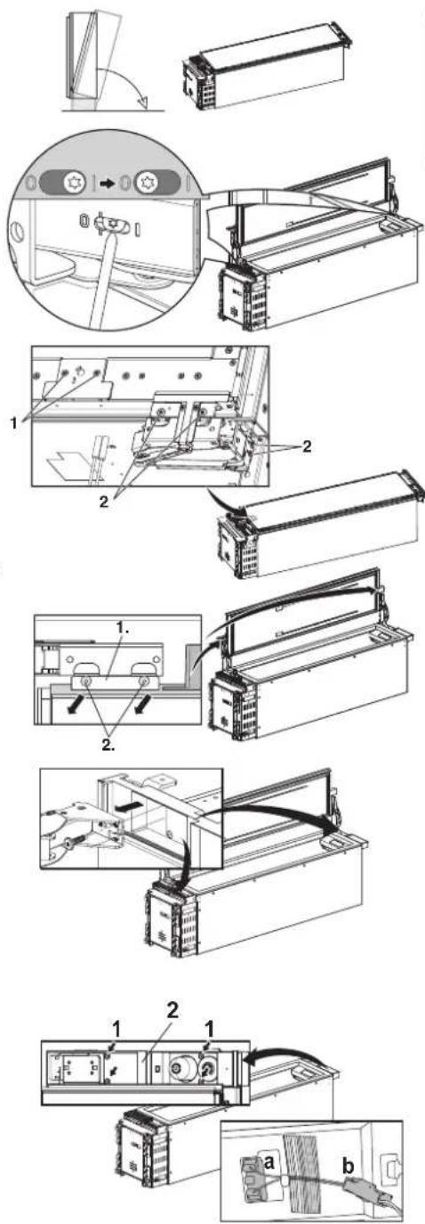
5b. (For wine columns only)
Remove the mounting bolts in the center front cover bracket (1) on the top of the appliance. Reinstall the bracket on the opposite side. Remove the mounting bolts in the left front cover bracket (2) and the upper hinge socket (3), swap their positions, and reinstall the bolts. Remove the mounting bolts in the upper right hinge socket (4) and replace it with the front cover bracket (5) provided in the installation accessories.
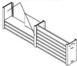
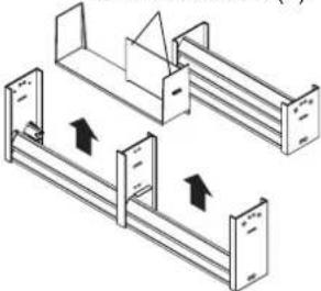
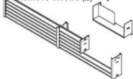
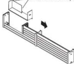
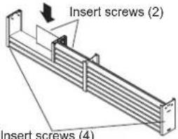
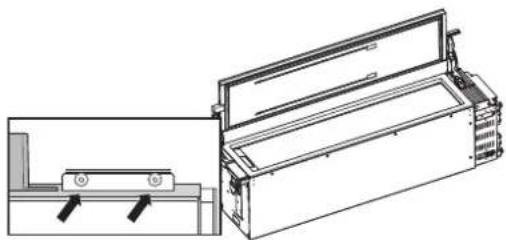
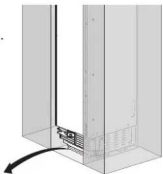
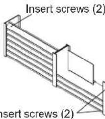
- Unscrew and remove the vent cover assembly at the bottom of the appliance. (For wine columns, the vent cover assembly was removed in step 2.)
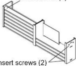
- Follow the diagrams below to disassemble and reassemble the vent grille. On refrigerator/freezer columns, screw the vent cover assembly back onto the appliance.(On wine columns, the vent cover assembly is reinstalled in step 13.)
18" Unit
Remove screws (4)
natural_image
Isometric line drawing of a multi-tiered storage unit or rack system (no text or symbols)Remove screws (2)
natural_image
Diagram of two mechanical assembly or ventilation system with directional arrows indicating flow or movement (no text or symbols)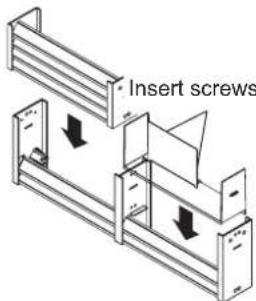
Insert screws (2)
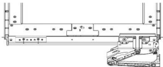
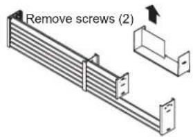
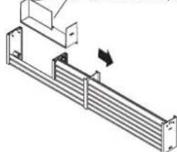
24"/30" Unit
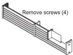
Remove screws (2)
natural_image
Technical line drawing of a structural bracket assembly (no text or symbols)Remove screws (2)
natural_image
Technical line drawing of a mechanical assembly with no visible text or symbolsInsert screws (2)
- Remove the lower hinge socket. Install the hinge socket provided in the installation accessories on the opposite side. Keep all parts in case door is reversed in future.
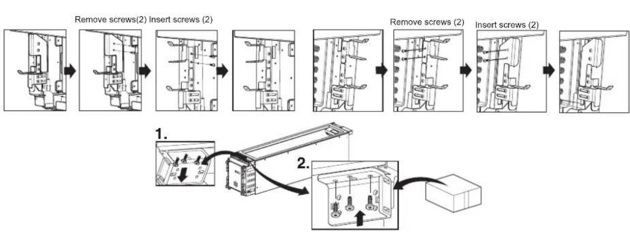
flowchart
graph TD
    A["Remove screws(2) Insert screws (2)"] --> B["Adder to 1. Panel"]
    B --> C["Remove screws (2) Insert screws (2)"]
    C --> D["Adder to 2. Panel with two switches"]
    D --> E["Final Assembly Unit"]
ENGLISH
- On the door, remove 2 bolts from the top hinge bracket and install the bracket on the opposite side of the door. Repeat with the bottom hinge bracket.
- Rotate the front cover 180 degrees and connect the reed switch connector(b) completely. Then reinstall the front cover at the top of the cabinet.
- Install the hinge removed from the top of the cabinet on the opposite side at the bottom of the cabinet. Install the hinge removed from the bottom of the cabinet on the opposite side at the top of the cabinet.
- Insert 2 bolts at the top and bottom of the door to reattach the door.
Note:
Do not exceed 97.36 inch-pounds (11Nm) of torque.
natural_image
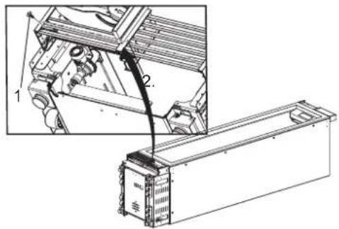
Technical line drawing of a mechanical device with two views (top and side), no text or symbols present.- (For wine columns only)
Reattach the PCB cover (1) with 2 screws. Use 4 screws to install the link on the hinge (2) at the opposite side from which it was removed. Reinstall the vent cover assembly reassembled in step 7.
natural_image
Technical line drawing of a mechanical assembly with mounting holes and a front-end truck (no text or symbols)
natural_image
Technical line drawing of a mechanical assembly with mounting holes and a side view showing internal components (no text or symbols)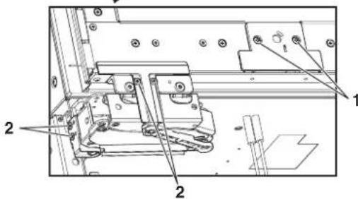
-
Reset the tension on the hinge spring by using the T20 bit provided to turn the tension screw from O to |.
-
Stand the product upright. The power cord can be connected, but wait 24 hours before turning on the power.
-
Make sure that the door switch is positioned correctly according to the guide structure(a), and the connector housing is connected completely(b).
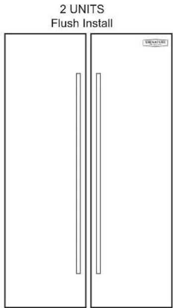
Side-by-Side Flush Installation
FLUSH INSTALLATION CLEARANCES
NOTE: When installing products with a partition between them, follow the standard installation. The minimum size of the partition is 6" (15.2 cm) to avoid interference between the doors.
DUAL 18" AND 30" COLUMN
(See custom panel pages for more configurations.)
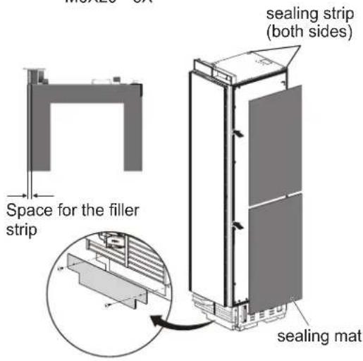
In a side-by-side flush installation, a unification kit must be used to seal the appliances together. A unification kit is included with all column freezers. The kit contains a sealing mat which helps prevent condensation from forming between the two appliances.
- Unpack the unification kit and make sure no accessories are missing.
- Place appliances near to each other in the intended installation configuration.
-
Remove the base panels from both appliances.
-
Attach the included sealing mat on the side of the freezer that faces the refrigerator. (The sealing mat should be between the two appliances after they are connected.)
Install the gray sealing mat over the preinstalled black sealing strips so that the edge of the mat is flush with the back edge of the freezer. This will leave a small space free at the front edge to fit the filler strip between the two appliances.
Additional unification kits can be purchased from Signature Kitchen Suite (part number SKSFJ800P).
NOTE:
When installing 2 side-by-side products with one left and one right door swing, 1/16" (2 mm) clearance is required between the products. This applies to both new installations and retrofit installations.
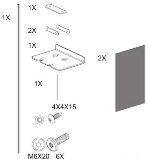
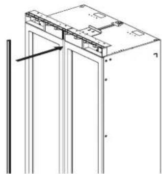
- Place the appliances right next to each other. Attach the two appliances together by installing connection brackets between the two appliances at top and bottom.
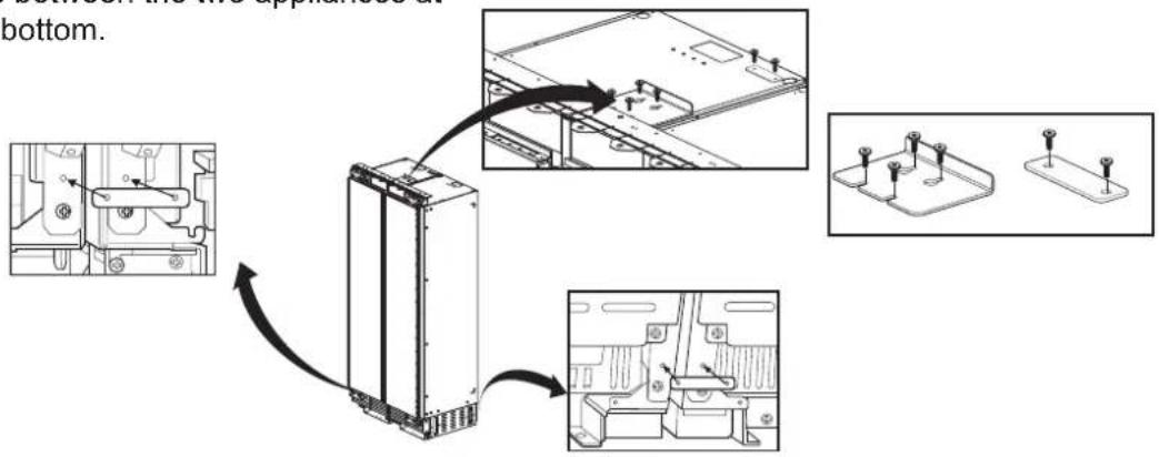
- Insert the provided pin into both cover rails at the top of the combined units.
NOTE:
If retrofit installing 18" and 30" columns in a 47 1/2" wide enclosure, trim 1/4" off of one side of both cover rails.
natural_image
Pure electrical circuit lines without any symbols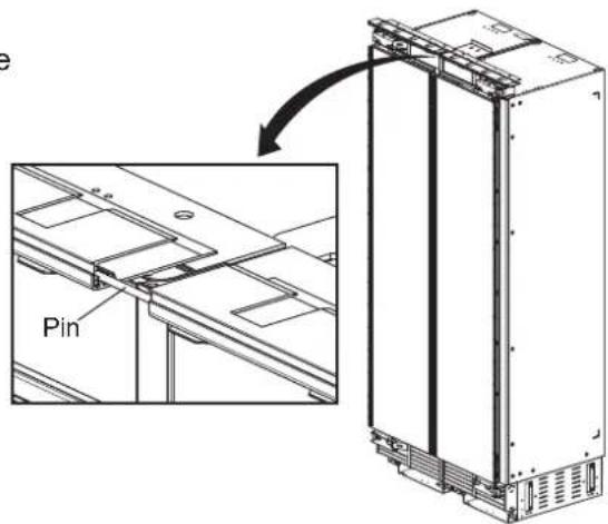
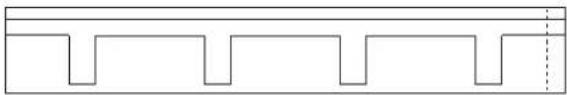
- Insert the filler strip in the space between the appliances. The filler strip is included with the unification kit.
natural_image
Technical line drawing of a mechanical assembly with vertical supports and a bracket (no text or symbols)Preparing to Connect the Water Line
NOTE:
Turn off the main water shutoff valve to prevent flooding and property damage.
Install the water line.
Always observe the indicated dimensions to prevent damage to the water line when pushing in the appliance
Connecting Water Line
NOTE:
When bending the water line, do not kink it, otherwise there is a risk of leaks and water damage.
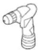
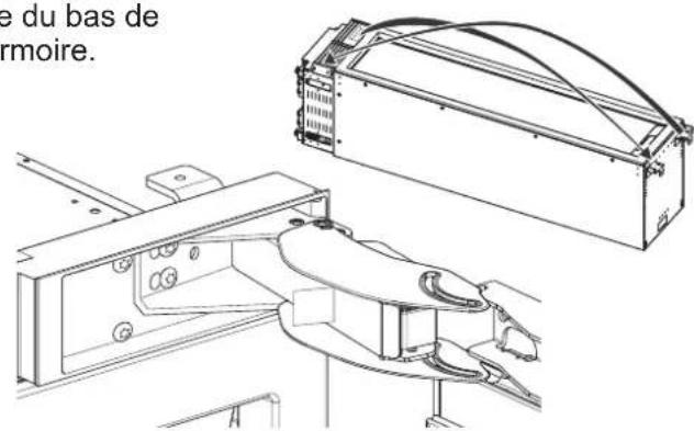
-
Remove the cap from the appliance connection (1.).
-
Bend the water line according to the location of the connection on the appliance (2.).
-
Push the union nut and seal onto the water line.
-
Push the end of the water line into the appliance connection and screw on the union nut (3.). Tighten hand-tight.
-
Using the open-ended wrench, tighten the union nut. Do not overturn.
natural_image
Diagram of a mechanical assembly with a vertical component and a curved arrow indicating motion (no text or symbols)
natural_image
Technical diagram of a mechanical piping system with no visible text or symbols
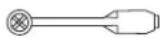
Attaching the Badge
- To install the badge, trace or cut out the template below and place it according to the panel layouts below.
- Align the template at the top corner nearest to the hinge and place the badge.

SIGNATURE
KITCHEN SUITE
SAFETY INSTRUCTIONS.... 3
Before Installation 6
Choosing the Install Location 6
Installation options 9
– Dimensions and Clearances
SKSCF1801P - 18" INTEGRATED
FREEZER COLUMN
SKSCW181RP - 18" INTEGRATED
WINE COLUMN 10
SKSCF2401P - 24" INTEGRATED
FREEZER COLUMN
SKSCR2401P - 24" INTEGRATED
REFRIGERATOR COLUMN
SKSCW241RP - 24" INTEGRATED
WINE COLUMN 12
SKSCF3001P - 30" INTEGRATED
FREEZER COLUMN
SKSCR3001P - 30" INTEGRATED
REFRIGERATOR COLUMN 14
- Custom Panels
SKSCF1801P - 18" INTEGRATED
FREEZER COLUMN
SKSCW181RP - 18" INTEGRATED
WINE COLUMN 16
SKSCF2401P - 24" INTEGRATED
FREEZER COLUMN
SKSCR2401P - 24" INTEGRATED
REFRIGERATOR COLUMN
SKSCW241RP - 24" INTEGRATED
WINE COLUMN 18
SKSCF3001P - 30" INTEGRATED
FREEZER COLUMN
SKSCR3001P - 30" INTEGRATED
REFRIGERATOR COLUMN 20
Required Accessories and Tools 22
Installation 23
Unpacking 24
Moving the Appliance 25
Special Circumstances 25
Product Dimensions 26
A
Installing the Anti-tip Brackets 29
Protecting Edges of Enclosure 30
Installing Appliance in Enclosure 31
B
Aligning and Leveling the Appliance 32
Attaching the Appliance to the Enclosure ..... 34
Attaching the Toe Kick Panel 35
C
Installing Door Panels 37
Adjusting Door Panels 38
Installing Door Trim 38
Attaching Air Separator 39
– Special Installations
Optional Frame Kit Accessory 39
Adjusting the Door Spring 40
Adjusting the Door Stop 40
Water Filter Bypass 40
Reversing the Door 41
Side-by-Side Flush Installation 45
Preparing to Connect the Water Line ..... 47
Connecting the Water Line 47
Attaching the Badge 48
CONSIGNES DE SÉCURITÉ
CONSIGNES DE SÉCURITÉ IMPORTANTES
REMARQUES
* Door handle must be added to this dimension.
**Varies depending on the thickness of the custom cabinet panel. The door panels in the optional Signature Kitchen Suite stainless steel door panel kit are 3/4" (19 mm) thick.

REMARQUES
REMARQUES
* Door handle must be added to this dimension.
**Varies depending on the thickness of the custom cabinet panel. The door panels in the optional Signature Kitchen Suite stainless steel door panel kit are 3/4" (19 mm) thick.
SKSCW241RP
REMARQUES
REMARQUES
* Door handle must be added to this dimension.
** Varies depending on the thickness of the custom cabinet panel. The door panels in the optional Signature Kitchen Suite stainless steel door panel kit are 3/4" (19 mm) thick.

REMARQUES
natural_image
Three vertical panels with rectangular cutouts, no text or symbols presentSKSPK180CS
SKSPK185CS
SKSWK185LS SKSWK185RS

AVERTISSEMENT
bar
| Column Type | Width (mm) | | ----------------------- | ---------- | | Single Column | 23 3/4" | | Single Column | 603 | | Single Column | 23 3/4" | | Single Column | 603 | | Single Column | 79 7/8" | | Single Column | 2029 | | Dual 24" AND 24" COLUMN | 47 3/4" | | Dual 24" AND 24" COLUMN | 1213 | | Dual 24" AND 24" COLUMN | 23 3/4" | | Dual 24" AND 24" COLUMN | 603 | | Dual 24" AND 24" COLUMN | 79 | | Dual 24" AND 24" COLUMN | 79 | | Dual 24" AND 24" COLUMN | 79 | | Dual 24" AND 24" COLUMN | 79 | | Dual 24" AND 30" COLUMN | 53 3/4" | | Dual 24" AND 30" COLUMN | 1365 | | Dual 24" AND 30" COLUMN | 23 3/4" | | Dual 24" AND 30" COLUMN | 603 | | Dual 24" AND 30" COLUMN | 756 | | Dual 24" AND 30" COLUMN | 79 | | Dual 24" AND 30" COLUMN | 79 | | Dual 24" AND 30" COLUMN | 79 |bar
| Column Type | Section | Height (mm) | |-------------|---------|-------------| | SINGLE COLUMN | Top Section | 23 3/4" | | SINGLE COLUMN | Middle Section | 23 3/4" | | SINGLE COLUMN | Bottom Section | 9 3/8" | | DUAL 24" AND 24" COLUMN | Top Section | 47 3/4" | | DUAL 24" AND 24" COLUMN | Middle Section | 23 3/4" | | DUAL 24" AND 24" COLUMN | Bottom Section | 79 7/8" | | DUAL 24" AND 30" COLUMN | Top Section | 53 3/4" | | DUAL 24" AND 30" COLUMN | Middle Section | 23 3/4" | | DUAL 24" AND 30" COLUMN | Bottom Section | 79 7/8" | | DUAL 24" AND 30" COLUMN | Bottom Section | 29 3/4" | | DUAL 24" AND 30" COLUMN | Bottom Section | 79 7/8" | The chart displays three vertical bars with precise measurements in mm. The top section contains a dimension label (603 mm), the middle section contains a dimension label (603 mm), and the bottom section contains a dimension label (238 mm). All values are explicitly labeled on the bars.REMARQUES
natural_image
Three vertical panels with rectangular cutouts, no text or symbols presentSKSPK240CS
SKSPK245CS
SKSWK245LS SKSWK245RS

AVERTISSEMENT
DUAL 30" AND 30" COLUMN
REMARQUES
natural_image
Simple line drawing of a door with a vertical bar on the left side (no text or symbols)SKSPK300CS SKSPK305CS
SKSPK300CS/SKSPK305CS – ENSEMBLE DE PANNEAU EN ACIER INOXYDABLE POUR LE CONGÉLATEUR/RÉFRIGÉRATEUR EN COLONNE DE 30 PO
flowchart
graph TD
    A["Refrigerator"] --> B["Block 1"]
    A --> C["Block 2"]
    A --> D["Block 3"]
    B --> E["Device 1"]
    C --> F["Device 2"]
    D --> G["Device 3"]
    E --> H["Component 1"]
    F --> I["Component 2"]
    G --> J["Component 3"]
    H --> K["Output"]
    I --> L["Output"]
    J --> M["Output"]
TOP VIEW
DOOR OPEN 90°

TOP VIEW
DOOR OPEN 115°

Unit width without door panel
TOP VIEW
DOOR OPEN 115°
Supports anti-basculement
(2)
! AVERTISSEMENT
Mise à niveau
natural_image
Technical diagram of a mechanical assembly with a magnified inset showing a bracket detail (no text or symbols)

4X15
4X
natural_image
Technical diagram showing a mechanical assembly with an inset close-up of a component (no text or symbols visible)

4X15
4X
natural_image
Diagram of a refrigerator with an arrow indicating rotation, showing structural components without any text or symbols.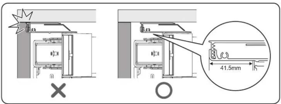
natural_image
Pure technical diagram showing a mechanical component inside a transparent enclosure (no text or symbols)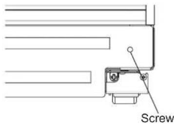
Panneau coup-de-pied en bois
natural_image
Technical diagram of a mechanical assembly with no visible text or symbolsI = Tension de ressort maximale
0 = Aucune tension du ressort
natural_image
Mechanical assembly diagram showing a component with an arrow pointing to a pin (no text or symbols present)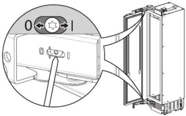
natural_image
Technical line drawing of a refrigerator interior with a close-up inset showing the exterior panel and door handle (no text or symbols)
natural_image
Technical line drawing of a mechanical assembly with mounting brackets and a directional arrow (no text or symbols)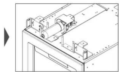
natural_image
Technical line drawing of a mechanical assembly with rollers and mounting brackets (no text or symbols)natural_image
Isometric line drawing of a multi-panel storage unit with no text or symbolsRemove screws (2)

natural_image
Technical line drawing of two mechanical assembly components with directional arrows indicating movement (no text or symbols)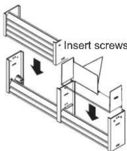
Remove screws (2)
natural_image
Technical line drawing of a mechanical assembly with no visible text or symbols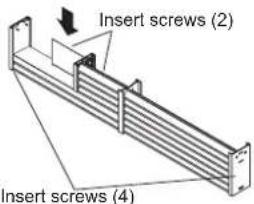
natural_image
Technical line drawing of a mechanical device with an open lid and side panel (no text or symbols)natural_image
Pure electrical circuit lines without any symbolsnatural_image
Technical line drawing of a mechanical assembly with vertical supports and a central component (no text or symbols)FRANÇAIS
natural_image
Diagram of a server rack with a vertical panel and base, showing internal components and a curved arrow indicating motion (no text or symbols)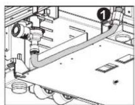
natural_image
Technical diagram of a mechanical assembly with pipes and housing (no visible text or labels)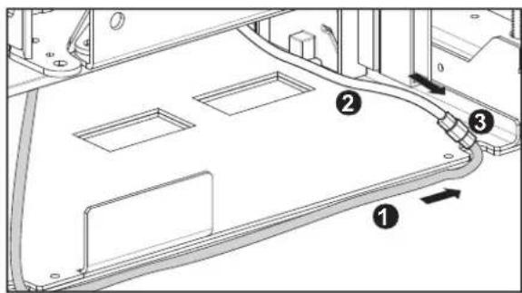
SAFETY INSTRUCTIONS.... 3
Before Installation 6
Choosing the Install Location 6
Installation options 9
– Dimensions and Clearances
SKSCF1801P - 18" INTEGRATED
FREEZER COLUMN
SKSCW181RP - 18" INTEGRATED
WINE COLUMN 10
SKSCF2401P - 24" INTEGRATED
FREEZER COLUMN
SKSCR2401P - 24" INTEGRATED
REFRIGERATOR COLUMN
SKSCW241RP - 24" INTEGRATED
WINE COLUMN 12
SKSCF3001P - 30" INTEGRATED
FREEZER COLUMN
SKSCR3001P - 30" INTEGRATED
REFRIGERATOR COLUMN 14
- Custom Panels
SKSCF1801P - 18" INTEGRATED
FREEZER COLUMN
SKSCW181RP - 18" INTEGRATED
WINE COLUMN 16
SKSCF2401P - 24" INTEGRATED
FREEZER COLUMN
SKSCR2401P - 24" INTEGRATED
REFRIGERATOR COLUMN
SKSCW241RP - 24" INTEGRATED
WINE COLUMN 18
SKSCF3001P - 30" INTEGRATED
FREEZER COLUMN
SKSCR3001P - 30" INTEGRATED
REFRIGERATOR COLUMN 20
Required Accessories and Tools 22
Installation 23
Unpacking 24
Moving the Appliance 25
Special Circumstances 25
Product Dimensions 26
A
Installing the Anti-tip Brackets 29
Protecting Edges of Enclosure 30
Installing Appliance in Enclosure 31
B
Aligning and Leveling the Appliance 32
Attaching the Appliance to the Enclosure ..... 34
Attaching the Toe Kick Panel 35
C
Installing Door Panels 37
Adjusting Door Panels 38
Installing Door Trim 38
Attaching Air Separator 39
– Special Installations
Optional Frame Kit Accessory 39
Adjusting the Door Spring 40
Adjusting the Door Stop 40
Water Filter Bypass 40
Reversing the Door 41
Side-by-Side Flush Installation 45
Preparing to Connect the Water Line ..... 47
Connecting the Water Line 47
Attaching the Badge 48
1 1/4" (32 mm) 7 7/8" (200 mm)
CORRECTO CORRECTO CORRECTO
*1 9/16" (40 mm)
*1 9/16" (40 mm)
**25/32" (20 mm)
**25/32" (20 mm)
*1 9/16" (40 mm)
**25/32" (20 mm)
NOTA
* Door handle must be added to this dimension.
**Varies depending on the thickness of the custom cabinet panel. The door panels in the optional Signature Kitchen Suite stainless steel door panel kit are 3/4" (19 mm) thick.
NOTA
NOTA
* Door handle must be added to this dimension.
**Varies depending on the thickness of the custom cabinet panel. The door panels in the optional Signature Kitchen Suite stainless steel door panel kit are 3/4" (19 mm) thick.

SKSCW241RP
NOTA
NOTA
* Door handle must be added to this dimension.
** Varies depending on the thickness of the custom cabinet panel. The door panels in the optional Signature Kitchen Suite stainless steel door panel kit are 3/4" (19 mm) thick.
NOTA
Columna cava
NOTAS
natural_image
Three vertical panels with rectangular cutouts, no text or symbols presentSKSPK180CS
SKSPK185CS
SKSWK185LS SKSWK185RS

ADVERTENCIA
bar
| Column Type | Window Name | Diameter (mm) | | ----------------------- | --------------- | ------------- | | SINGLE COLUMN | Door Panel | 23 3/4" | | SINGLE COLUMN | Door Panel | 23 3/4" | | SINGLE COLUMN | Door Panel | 79 7/8" | | DUAL 24" AND 24" COLUMN | Door Panel | 47 3/4" | | DUAL 24" AND 24" COLUMN | Door Panel | 23 3/4" | | DUAL 24" AND 24" COLUMN | Door Panel | 23 3/4" | | DUAL 24" AND 24" COLUMN | Door Panel | 79 7/8" | | DUAL 24" AND 24" COLUMN | Door Panel | 53 3/4" | | DUAL 24" AND 24" COLUMN | Door Panel | 23 3/4" | | DUAL 24" AND 24" COLUMN | Door Panel | 29 3/4" | | DUAL 24" AND 24" COLUMN | Door Panel | 79 7/8" | | DUAL 24" AND 30" COLUMN | Door Panel | 53 3/4" | | DUAL 24" AND 30" COLUMN | Door Panel | 23 3/4" | | DUAL 24" AND 30" COLUMN | Door Panel | 603 mm | | DUAL 24" AND 30" COLUMN | Door Panel | 29 3/4" | | DUAL 24" AND 30" COLUMN | Door Panel | 756 mm | | DUAL 24" AND 30" COLUMN | Door Panel | 79 7/8" |Columna cava

bar
| Column Type | Total Height (mm) | Base Height (mm) | |-------------|-------------------|------------------| | Single Column | 23 3/4" (603 mm) | 7 1/16" (179.5 mm) | | Single Column | 23 3/4" (603 mm) | 3 3/16" (80.5 mm) | | Single Column | Door Panel | 9 3/8" (238 mm) | | Dual 24" AND 24" COLUMN | 47 3/4" (1213 mm) | 79 7/8" (2029 mm) | | Dual 24" AND 24" COLUMN | 23 3/4" (603 mm) | 79 7/8" (2029 mm) | | Dual 24" AND 24" COLUMN | Door Panel | 23 3/4" (603 mm) | | Dual 24" AND 24" COLUMN | Door Panel | 29 3/4" (756 mm) | | Dual 24" AND 24" COLUMN | Door Panel | 79 7/8" (2029 mm) | | Dual 24" AND 30" COLUMN | 53 3/4" (1365 mm) | — | | Dual 24" AND 30" COLUMN | — | — | | Dual 24" AND 30" COLUMN | — | — | | Dual 24" AND 30" COLUMN | — | — | | Dual 24" AND 30" COLUMN | — | — | | Dual 24" AND 30" COLUMN | — | — | | Dual 24" AND 30" COLUMN | — | — | | Dual 24" AND 30"COLUMN | — | — | | Dual 24" AND 30"COLUMN | — | — | | Dual 24" AND 30"COLUMN | — | — | | Dual 24" AND 30"COLUMN | — | — | | Dual 24" AND 30"COLUMN | — | — | | Dual 24" AND 30"COLUMN | — | — | | Dual 24" AND 31" COLUMN | — | — | | Dual 24" AND 31" COLUMN | — | — | | Dual 24" AND 31" COLUMN | Door Panel | Door Panel | | Dual 24" AND 31" COLUMN | Door Panel | Door Panel | | Dual 24" AND 31" COLUMN | Door Panel | Door Panel | | Dual 24" AND 31" COLUMN | Door Panel | Door Panel | | Dual 24" AND 31" COLUMN | Door Panel | Door Panel | | Dual 24" AND 31" COLUMN | Door Panel | Door Panel | | Dual 16 Column | — | — | | Dual 16 Column | — | — | | Dual 16 Column | — | — | | Dual 16 Column | Door Panel | Door Panel | | Dual 16 Column | Door Panel | Door Panel | | Dual 16 Column | Door Panel | Door Panel | | Dual 16 Column | Door Panel | Door Panel | | Dual 16 Column | Door Panel | Door Panel | | Dual 16 Column | Door Panel | Door Panel | | Dual 16 Column | Door Panel | Door Panel | | Dual 16 Column | Door Panel | Door Panel | | Dual 16 Column | — | — | | Dual 16 Column | — | — | | Dual 16 Column | — | — | | Dual 16 Column | — | — | | Dual 16 Column | — | — | | Dual 16 Column | — | — | | Dual 16 Column | — | — | | Dual 16 Column | — | — | | Dual 16 Column | — | — | | Dual 16 Column | — | — |NOTAS
SKSWK245LS SKSWK245RS
SKSPK245CS
ADVERTENCIA
DUAL 30" AND 30" COLUMN
NOTAS
natural_image
Simple line drawing of a door with a vertical bar on the left side (no text or symbols)SKSPK300CS SKSPK305CS
SKSPK300CS/SKSPK305CS - KIT DE PANEL DE ACERO INOXIDABLE PARA COLUMNNA CONGELADOR/REFRIGERADOR DE 30"
TOP VIEW
DOOR OPEN 90°
TOP VIEW
DOOR OPEN 115°

Unit width without door panel
Columna congelador/refrigerador/cava de 24"

TOP VIEW
DOOR OPEN 90°
TOP VIEW
DOOR OPEN 115°
Columna congelador/refrigerador de 30"
FRONT VIEW
SIDE VIEW

TOP VIEW
DOOR OPEN 90°
TOP VIEW
DOOR OPEN 115°
A
B
natural_image
Isometric line drawing of a structural support frame with no text or symbolsGauge tool
AJUSTE DE LA ALTURA
flowchart
graph TD
    subgraph Left
        A1["Raise Product"] --> B1["Rear"]
        B1 --> C1["Front"]
        C1 --> D1["Raise Product"]
    end
    subgraph Right
        E1["Raise Product"] --> F1["Rear"]
        F1 --> G1["Front"]
        G1 --> H1["Raise Product"]
    end
Nivelación

natural_image
Technical diagram of a mechanical assembly with a magnified inset showing a bracket detail (no text or symbols)
4X15 4X

natural_image
Technical diagram showing a mechanical assembly with a magnified inset view (no text or symbols)
4X15 4X
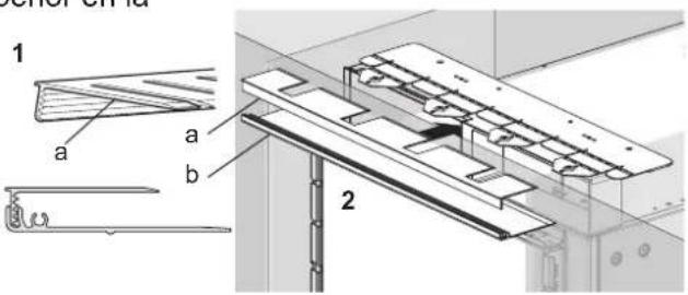
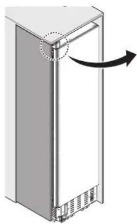
natural_image
Diagram of a refrigerator with an arrow indicating rotation or movement, showing no text or symbols.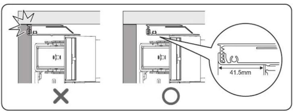
natural_image
Pure technical diagram showing a mechanical component inside a transparent enclosure, without any text, numbers, or symbols.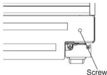
Panel del zócalo de madera
natural_image
Technical diagram of a mechanical assembly with directional arrows indicating motion or force (no text or symbols present)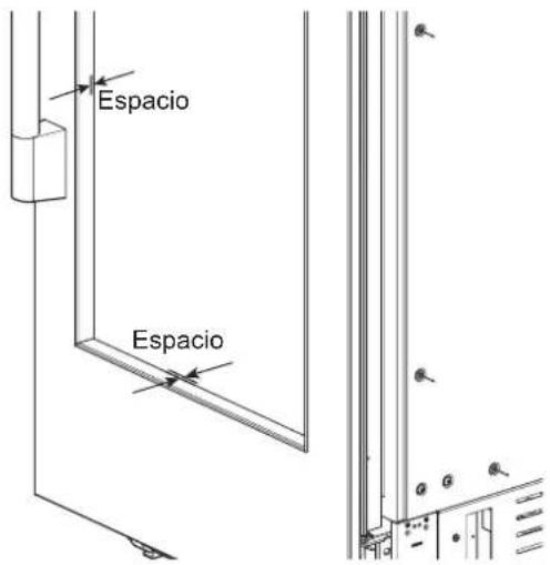
natural_image
Mechanical assembly diagram showing a component with an arrow pointing to a pin (no text or symbols present)
natural_image
Technical line drawing of a refrigerator interior with a close-up inset showing the exterior panel and door (no text or symbols)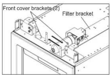

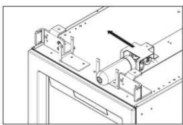
natural_image
Technical line drawing of a mechanical assembly with no visible text or symbols
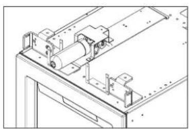
natural_image
Technical line drawing of a mechanical assembly with no visible text or symbols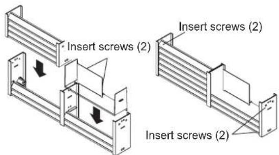
Unidad de 24"/30"
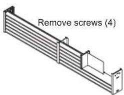
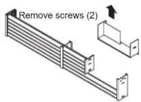
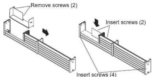
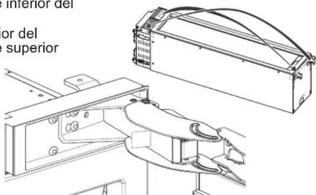
natural_image
Technical line drawing of a mechanical device with an open lid and side view (no text or symbols)- (Solo para columnas cava)
natural_image
Technical diagram of a mechanical device with an inset close-up showing a control panel (no text or symbols present)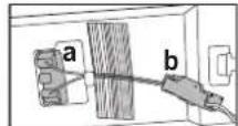
DUAL 18" AND 30" COLUMN
(See custom panel pages for more configurations.)
47 3/4" (1213 mm)
17 3/4"
(451 mm)
29 3/4"
(756 mm)
NOTA:
natural_image
Pure electrical circuit lines without any symbolsnatural_image
Technical line drawing of a mechanical assembly with vertical supports and a central component (no text or symbols)ESPAÑOL
natural_image
Diagram of a server rack with a vertical panel and internal components, showing no text or symbols
natural_image
Technical diagram of a mechanical piping system with no visible text or symbols


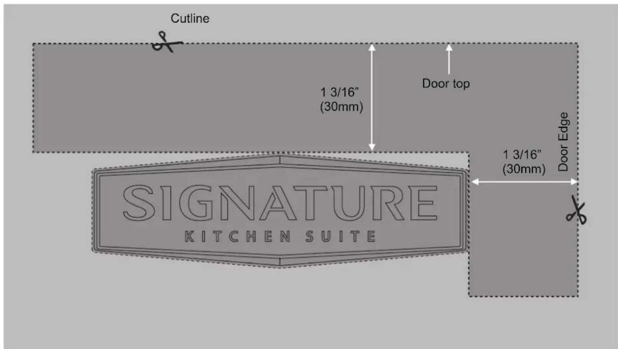


SIGNATURE
KITCHEN SUITE
Customer Information Center
For inquires or comments, call;
1-855-790-6655 USA, Consumer User
1-888-289-2802 CANADA, Consumer User