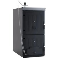
SOLIDA EV - Camera SIME - Free user manual and instructions
Find the device manual for free SOLIDA EV SIME in PDF.


| Product type | Cast iron wood boiler |
| Brand | SIME |
| Model | SOLIDA EV |
| Wood thermal power range | From 14.0 kW (model 3) to 40.0 kW (model 7) |
| Maximum wood power | From 20.0 kW (model 3) to 58.0 kW (model 7) |
| Coal thermal power | From 23.0 kW (model 3) to 67.0 kW (model 7) |
| Efficiency class EN 303-5/2012 | 1 (or 3 with optional kit) |
| Dimensions (total depth) | From 425 mm (model 3) to 1025 mm (model 7) |
| Combustion chamber depth | From 260 mm (model 3) to 860 mm (model 7) |
| Weight | From 226 kg (model 3) to 474 kg (model 7) |
| Boiler capacity | From 30 L (model 3) to 66 L (model 7) |
| Loading volume (wood) | From 42.7 dm³ (model 3) to 137.7 dm³ (model 7) |
| Single load duration (wood) | ≥ 2 hours |
| Single load duration (coal) | ≥ 4 hours |
| Maximum operating temperature | 95 °C |
| Minimum return temperature | 50 °C |
| Maximum operating pressure | 4 bar |
| Test pressure | 6 bar |
| Minimum chimney draft | From 0.08 mbar (model 3) to 0.13 mbar (model 7) |
| Hydraulic connections | Flow and return: 2" (UNI-ISO 7/1); drain: 1/2" (UNI-ISO 7/1) |
| Fuel | Wood or coal (solid fuel) |
| Regulation | Thermostatic draft regulator (Thermomat RT-C or Regulus RT2) |
| Maintenance | Annual cleaning of flue gas passages and ash pan; annual check of safety valve |
| Spare parts and repairability | Use only original spare parts; intervention by qualified technician |
| Standards | PED Directive 2014/68/EU, standard EN 303-5/2012 |
Frequently Asked Questions - SOLIDA EV SIME
User questions about SOLIDA EV SIME
0 question about this device. Answer the ones you know or ask your own.
Ask a new question about this device
Download the instructions for your Camera in PDF format for free! Find your manual SOLIDA EV - SIME and take your electronic device back in hand. On this page are published all the documents necessary for the use of your device. SOLIDA EV by SIME.
USER MANUAL SOLIDA EV SIME
natural_image
Exterior view of a modern black industrial oven or storage unit with open doors and side-mounted fans (no visible text or symbols)IT
RO
SL
PT
RUS
ES
FR
ENG
DE
Gentile Cliente,
natural_image
Technical line drawing of a mechanical device with internal components and mounting holes (no text or symbols)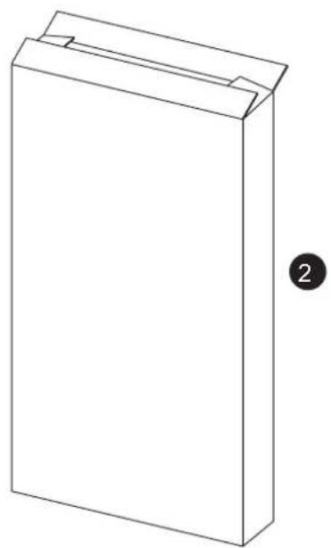
natural_image
Simple line drawing of a rectangular box with a cutout, labeled with number 2 (no text or symbols on the box itself)Fig. 1
3 CARATTERISTICHE TECNICHE E DIMENSIONALI
3.1 DESCRIZIONE
$$ S = \frac {Q}{1 0 0} $$
natural_image
Technical line drawing of an open industrial machine with internal components and mounting holes (no text or symbols)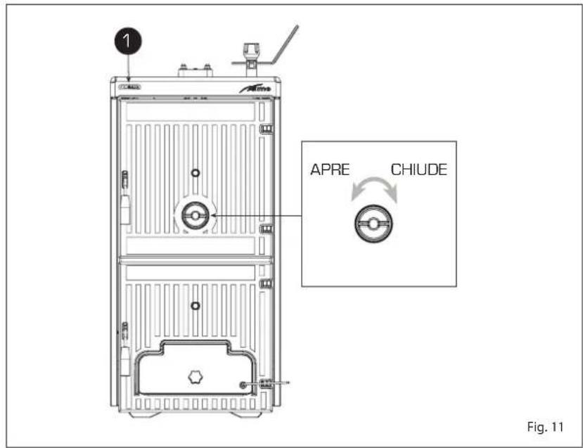

natural_image
Technical line drawing of an open refrigerator with internal compartments and ventilation slots (no text or symbols)5.5 MANUTENZIONE
natural_image
Technical line drawing of a mechanical device with internal components and mounting holes (no text or symbols)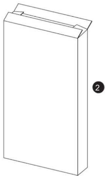
natural_image
Simple line drawing of a rectangular box with a folded top and a label '2' on the right side (no text or symbols on the box itself)Fig. 1
3 CARACTERÍSTICAS TÉCNICAS E DIMENSIONAIS
3.1 DESCRICÃO
natural_image
Technical line drawing of an open industrial machine with internal components and a directional arrow indicating flow (no text or symbols present)Fig. 12
ÍNDICE
natural_image
Technical line drawing of a mechanical device with internal components and mounting brackets (no text or symbols)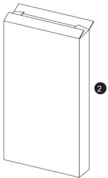
natural_image
Simple line drawing of a rectangular box with a cutout, labeled with number 2 (no text or symbols on the object itself)Fig. 1
3 ESPECIFICACIONES TÉCNICAS Y DIMENSIONES
3.1 DESCRIPCIÓN
$$ S = \frac {Q}{1 0 0} $$
natural_image
Technical line drawing of an open industrial machine with internal components and ventilation ducts (no text or symbols)INDEX
1 MAIN WARNINGS 34
2 SUPPLY 34
3 DIMENSIONAL TECHNICAL CHARACTERISTICS.... 35
3.1 DESCRIPTION
3.2 OVERALL DIMENSIONS
3.3 TECHNICAL DATA
3.4 PRESSURE DROP
4 INSTALLATION.... 37
4.1 BOILER ROOM
4.2 CONNECTION TO THE CHIMNEY
4.3 CONNECTION TO THE SYSTEM
4.4 ASSEMBLING THE ACCESSORIES
4.5 ASSEMBLING THE CASING
4.6 DRAUGHT REGULATOR
4.7 SAFETY EXCHANGER
4.8 HYDRAULIC CONNECTION DIAGRAMS
5 USE AND MAINTENANCE.... 41
5.1 PRELIMINARY CHECKS BEFORE COMMISSIONING
5.2 BOILER THERMOMETER
5.3 AIR ADJUSTMENT
5.4 CLEANING
5.5 MAINTENANCE
5.6 DISPOSAL OF THE EQUIPMENT
1 MAIN WARNINGS
The instruction manual is an integral part of the product and must be delivered to the user. Carefully read the warnings contained in the manual on installation, use and maintenance of the appliance. Carefully store the manual for future reference.
Installation must be carried out by qualified personnel in compliance with the standards in force and following the instructions provided by the manufacturer. Improper installation can damage persons or objects, which the company is not responsible for.
Ensure that the product is intact. In case of doubt, do not use the appliance and contact the supplier. Packaging components must be disposed of in compliance with the standards in force.
Before any maintenance operation on the appliance, disconnect the power supply using the system switch.
In case of failure or malfunction, deactivate the appliance avoiding any repair or direct intervention. Only refer to qualified techni-
cal personnel. Any repair must be carried out by using original spare parts only.
Failure to comply with that above can compromise the integrity of the system and single components, being a potential danger for the user's safety, which the company is not responsible for.
Maintenance of the appliance and chimney is required at least once a year.
2 SUPPLY
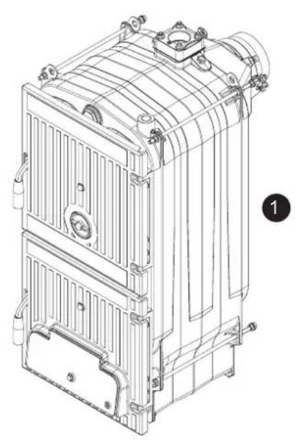
As indicated in fig. 1, the boiler is supplied in two different packaging:
- Cast iron boiler body with flue gas chamber and adjusting dampers, ash collecting tray and draught thermostatic regulator. A bag containing: 2 handles for the ports, one screw with bakelite knob for manually adjusting the air gate dumper, a contact spring for the thermometer bulb and a M6 lever to be fastened to the air gate dumper. "Test report" and "De
claration of conformity" to be stored together with the documents of the boiler.
- Carton packaging with casing, thermometer and document kit. The document kit includes: instruction manual, warranty certification, BOILER TECHNICAL DATA plate and label module to apply on the declaration of conformity.
ATTENTION: The BOILER TECHNICAL DATA plate included in the document kit is
adhesive and must be applied on a side of the casing by the installer.
The serial number of the iron case body is indicated on the riveted plate on the rear upper side of the body.
To facilitate transport, the load and drain of the boiler are placed on the upper side and are equipped with lifting hooks.
natural_image
Technical line drawing of a mechanical device with internal components and mounting holes (no text or symbols)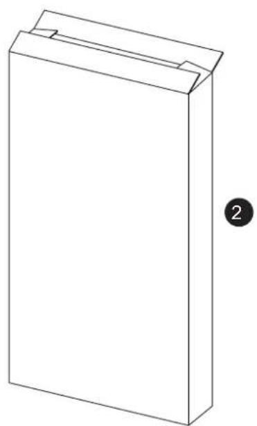
natural_image
Simple line drawing of a rectangular box with a folded top and a label '2' on the right side (no text or symbols on the box itself)Fig. 1
3 TECHNICAL AND DIMENSIONAL CHARACTERISTICS
3.1 DESCRIPTION
Wood is an alternative source of energy and it is also precious; therefore, use it in the
best way using suitable technologies for combustion.
Iron cast and traditional combustion wood boilers SOLIDA EV are designed to en-
sure maximum thermal yield optimising draught. The boilers are in compliance with PED Directive 2014/68/UE and Standard EN 303-5/2012.
3.2 OVERALL DIMENSIONS (fig. 2)
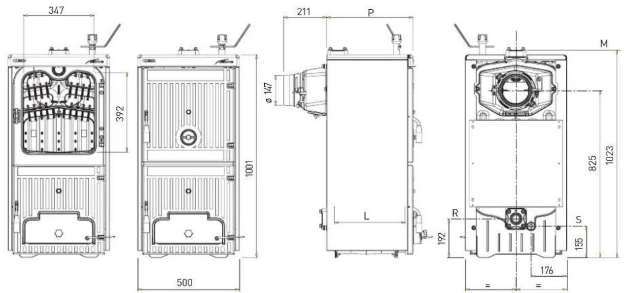
M C.H. flow 2" (UNI-ISO 7/1)
R C.H. return 2" (UNI-ISO 7/1)
S Boiler drain 1/2" (UNI-ISO 7/1)
Fig. 2
3.3 TECHNICAL DATA
| SOLIDA EV | 3 | 4 | 5 | 6 | 7 | ||
| Coal-fired thermal output | kW | 23.0 | 34.0 | 45.0 | 56.0 | 67.0 | |
| Maximum power at wood kW | 20.0 | 30.0 | 40.0 | 49.0 | 58.0 | ||
| Wood load thermal output kW | 14.0 | 20.5 | 27.5 | 34.0 | 40.0 | ||
| Performance class EN 303-5/2012 | 1 | 1 | 1 | 1 | 1 | ||
| Duration of a coal-fired | h | ≥4 | ≥4 | ≥4 | ≥4 | ≥4 | |
| Duration of a wood load | h | ≥2 | ≥2 | ≥2 | ≥2 | ≥2 | |
| Load volume | dm ^3 | 42,7 | 66,4 | 90,2 | 113,9 | 137,7 | |
| Minimum chimney depression | mbar | 0.08 | 0.10 | 0.12 | 0.13 | 0.15 | |
| Dimensions | |||||||
| P (depth) | mm | 425 | 575 | 725 | 875 | 1025 | |
| L (combustion chamber depth) | mm | 260 | 410 | 560 | 710 | 860 | |
| Number of elements | n° | 3 | 4 | 5 | 6 | ||
| Max. operating temperature | °C | 95 | 95 | 95 | 95 | 95 | |
| Min. temperature of water returned to the plant | °C | 50 | 50 | 50 | 50 | 50 | |
| Max working pressure | bar | 4 | 4 | 4 | 4 | 4 | |
| Test pressure | bar | 6 | 6 | 6 | 6 | 6 | |
| Boiler capacity | l | 30 | 39 | 48 | 57 | 66 | |
| Weight | kg | 226 | 288 | 350 | 412 | 474 | |
7
4
3.3.1 Technical data with kit that can be switched from class 1 to class 3 (to be requested separately)
| SOLIDA EV | 3 | 4 | 5 | 6 | 7 |
| Kit that can be switched from class 1 to class 3 | 8075990 | 8075991 | 8075992 | 8075993 | |
| Heat capacity with wood | kW | 11,0 | 17,5 | 24,0 | 29,5 |
| Wood load thermal output | kW | 8,4 | 13,7 | 19.0 | |
| Performance class EN 303-5/2012 | 3 | 3 | 3 | 3 | |
| Duration of a wood load | h | ≥ 2 | ≥ 2 | ≥ 2 | ≥ 2 |
| Load volume | dm^3 | 37,5 | 58,3 | 79,2 | 100,0 |
| Minimum chimney depression | mbar | 0,20 | 0,20 | 0,20 | 0,20 |
3.4 HEAD LOSSES (fig. 3)
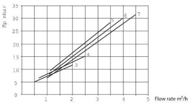
line
| Flow rate m³/h | Fp mbar (Line 3) | Fp mbar (Line 4) | Fp mbar (Line 5) | Fp mbar (Line 6) | Fp mbar (Line 7) | | -------------- | ---------------- | ---------------- | ---------------- | ---------------- | ---------------- | | 1 | 5 | 7 | 9 | 10 | 11 | | 2 | 10 | 13 | 16 | 18 | 20 | | 3 | 15 | 19 | 23 | 26 | 29 | | 4 | 20 | 25 | 30 | 33 | 36 | | 5 | 25 | 30 | 35 | 38 | 41 |Fig. 3
4 INSTALLATION
4.1 BOILER ROOM
Check that the room has the requirements and features in accordance to the rules in force. Furthermore, the room should be aired, in order to have a regular combustion. Therefore it is necessary to practice some openings in the walls of the room, which correspond to the following requirements:
- They should have a free section of at least 6cm^2 for each 1,163 kW (1000 kcal/h). The minimum opening section shouldn't be smaller than 100~cm^2 . The section can also be calculated, using the following ratio:
$$ s ^ {Q} = \frac {}{1 0 0} $$
where "S" is expressed in cm ^2 .
"Q" is expressed in kcal/h
- The opening should be situated on the lower part of an outer wall, preferably on the opposite of the one for the combustion gas discharge.
4.1.1 Positioning in the power station (fig. 4)
The boiler must be installed on a non-combustion base.
Once the boiler has been installed, it must be horizontal and stable, in order to reduce any vibrations and noise.
Always leave free space behind the boiler, so as to allow opening and maintenance on the fan.
CAUTION: The minimum distances indicated in the figure are bounding and only refer to models with power exceeding 35 kW.
4.2 CONNECTION TO THE FLUE
A flue should correspond to the following requirements:
- It should be of waterproof material and
resistant to temperature of smokes and related condensations.
- It should be of a sufficient mechanical resistance and a weak thermal conductivity.
- It should be perfectly hermetic in order to avoid cooling of the flue.
- It should have the most possible vertical process and the terminal part should have a static aspirator, which assures an efficient and constant discharge of the combustion product.
- In order to avoid the wind creating a very high pressure around the chimneypot, so that it prevails on the ascensional force of the combustion gas, it is necessary that the discharge orifice hangs over at least 0,4 meters of whatever structure adjacent the chimney itself (including the roof ridge) of at least 8 meters.
- The flue shouldn't have a diameter inferior to the boiler connection; for flues with square or rectangular sections, the internal section should be higher than 10% compared to the boiler connection one.
- The net section of the flue can be obtained from the following ratio:
$$ S = K \frac {P}{\sqrt {H}} $$
S section resulting in cm 2
K reduction coefficient:
- 0,045 for wood
- 0,030 for carbon
P boiler capacity in kcal/h
H height of the chimney in meters measured from the flame axis at the exhaust of the chimney in the atmosphere. For the dimensioning of the flue you should consider the effective height of the chimney in meters, measured from the flame axis at the top, diminished with:
- 0,50 m for each direction changing of the connection tube between boiler and flue;
- 1,00 m for each horizontal development meter of the connection itself.
4.3 CONNECTION OF THE PLANT
The connections should be easily disconnected by means of pipelines with revolving joints. It is always advisable to assemble suitable interception shutters on the piping of the heating installation.
CAUTION: It is obligatory to assemble safety valves on the system not included in supply.
4.3.1 Filling the system
Before connecting the boiler, it is good practice to make water circulate inside the pipes to remove any foreign body that can compromise the proper operation of the apparatus.
The filling operation must be carried out slowly to allow air bubbles to exit from the specific vents placed on the heating system.
In closed circuit heating systems, the cold loading pressure of the system and the pre-inflating pressure of the expansion tank must correspond, or at least not be lower than the height of the system static column (e.g., for a 5 m static column, the pre-load pressure of the tank and the load pressure of the system must correspond to the minimum value of 0.5 bars, at least).
4.3.2 Features of the feed water
The heating circuit supply water must be treated in compliance with Standard UNI-COI 8065.
Remember that even small deposits of few millimetres thick cause a considerable over-heating of the boiler walls, resulting in serious consequences.
THE TREATMENT OF THE WATER USED FOR THE HEATING INSTALLATION IS ABSOLUTELY NECESSARY IN THE FOLLOWING CASES:
- Very vast plants (with high water con-
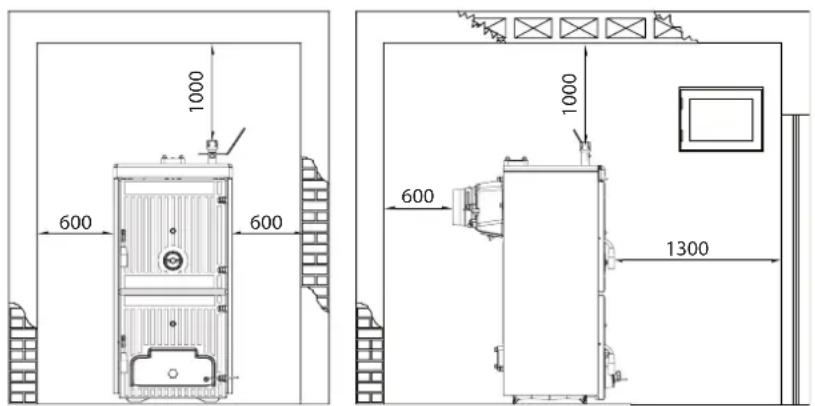
Fig. 4
tents).
- Frequent replenishment water inlets in the plant.
- If the partial or total emptying of the plant should be necessary.
4.4 ASSEMBLING
THE ACCESSORIES
(fig. 5 - fig. 5/a)
The port closing handles and the screw with knob for the air gate damper regulation is supplied separately, as they can be damaged during transport.
Both the handles and the screw with knob are contained in nylon bags inside the ash collecting tray.
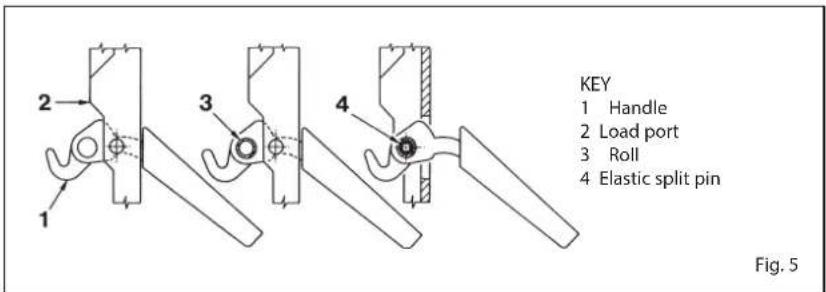
To assemble the handles, proceed in the following way (fig. 5):
- Take a handle (1), insert it in the load port slot (2) and insert the roll (3) inside the handle hole; block the handle by inserting the elastic split pin (4).
- Carry out the same operation for the handle of the ash-pit port.
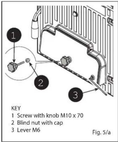
To assemble the screw with knob, proceed in the following way (fig. 5/a):
- Remove screw M8 x 60 that fastens the air gate damper to the ash-pit port and
tighten the screw with Bakelite knob (1) supplied. Place the blind nut with cap (2) at the end of screw M 10.
- Fasten lever M6 (3) to the air gate damper placing it in a horizontal direction on the right. The lever has an opening at its end, where the chainlet of the thermostatic regulator will be connected.
4.5 ASSEMBLING
THE CASING
(fig. 6)
From the rear of the boiler, on two upper tie rods, three nuts are tightened: the second and the third nut serve to place correctly the lateral sides of the casing. On the lo-
KEY
1 Screw with knob M10 x 70
2 Blind nut with cap
3 Lever M6
Fig. 5/a
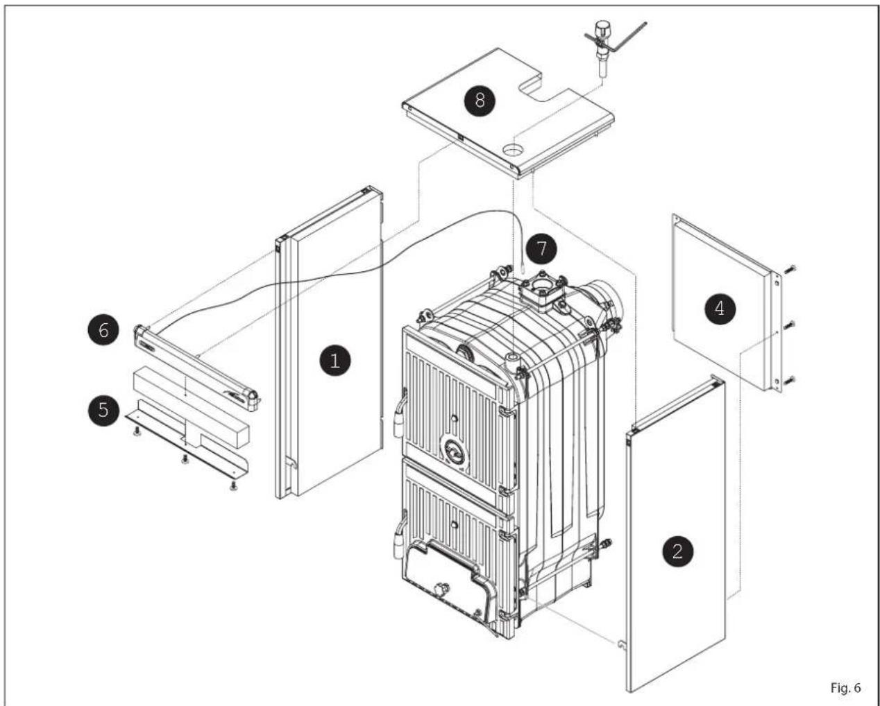
wer tie rods, both in the front and rear side of the boiler, two nuts are tightened, one of which is used to block the side support brackets.
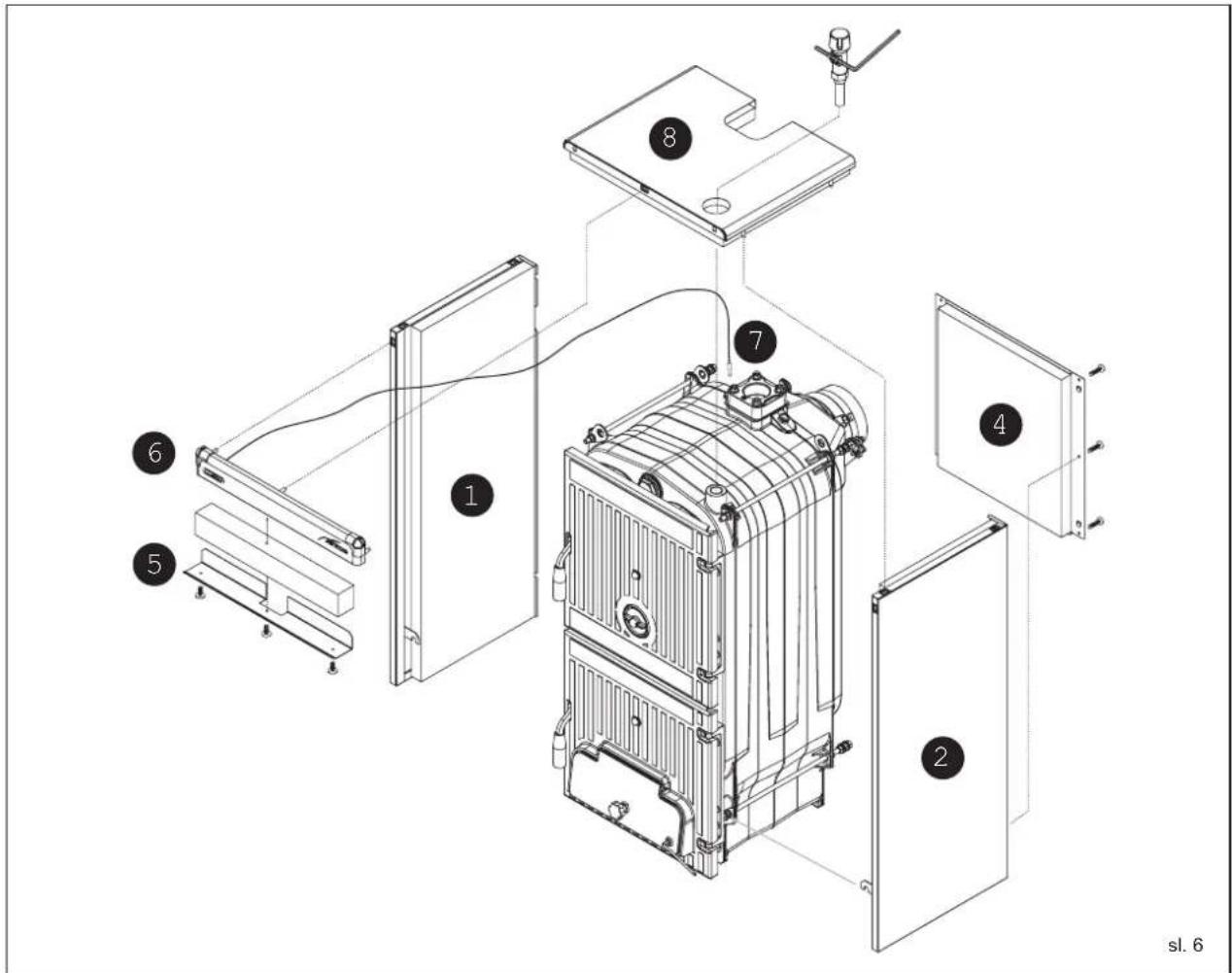
The assembly of the casing components must be carried out in the following way:
- Unscrew with some rotations the second or third nut of each tie rod.
- Connect the left side (1) on the lower and upper tie rod of the boiler and adjust the position of the nut and lock-nut of the upper tie-rod.
- Block the side by tightening the locknuts.
- In order to assembly the right side (2) proceed in the same way.
- Connect the rear panel (4) introducing the two splines in the vents obtained on each side and lock it with self-threading screws.
- The protection deflector (5) is fixed to the control panel (6) with three self-threading screws. Insert the mineral wool between the two components.
- Fasten the front panel (6) using the pressure pins.
- Unwind the capillary of the thermometer (7) and introduce it in the left sheath of the rear head introducing the contact spring which must be cut at about 45 mm. The thermometer cable must be placed above the insulation and must not contact directly the iron cast body.
- Fasten the cover (8) to the sides of the boiler using the pressure pins.
- Apply the BOILER TECHNICAL DATA adhesive plate on the right or left side of the covering, so as to be legible when the appliance is installed.
NOTICE: Store the "Test report" and "Declaration of conformity" placed in the combustion chamber together with the documents of the boiler.
4.6 DRAUGHT REGULATOR WITH THERMOSTATIC OPERATION
By means of the draught regulator with thermostatic operation, a continuous variability of the air introduced in the boiler furnace can be obtained.
By means of a connecting chainlet, this regulator acts on the lower primary air intake port.
Once the set temperature has been reached, the regulator decreases the opening of the air intake port automatically, so to slow down the combustion and prevent over-heating.
In order to optimise the combustion on the upper load port, place a round adjusting port that distributes the secondary air countercurrent compared to the path of the combustion products.
This process further increases the yield and allows exploiting the combustion more effectively.
Two types of thermostatic regulators can be assembled on the boilers.
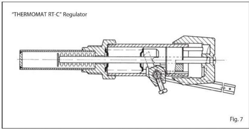
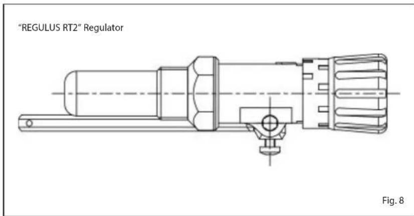
4.6.1 "THERMOMAT RT-C" Regulator (fig. 7)
The "Thermomat" regulator is equipped with a thermosetting resin knob of an adjustment field from 30 to 100^ .
Screw the regulator on the 3/4" opening of the anterior head and orientate the red index on the upper part.
The lever with the chainlet should be introduced in the regulator holder after having assembled the instrument holder board and after having removed the plastic lock.
If the joint is taken out, which fixes the lever with the chainlet, take care in assembling it again in the same position.
After having placed the knob at 60°C, block the lever with the chainlet in a slightly inclined position downwards, so that the chainlet will be in axis with the air gate damper. For the adjustment of the "Thermomat", which essentially consists in the determination of the chainlet length, proceed in the following way:
- Place the knob at 60°C.
- Switch on the boiler with opened air gate damper.
- When the water temperature of 60^ is reached in the boiler, fix the chainlet in such a way on the lever of the air gate damper, in order to obtain an opening of about 1 mm.
- Now the regulator is calibrated and it is possible to choose the desired operating temperature by rotating the knob.
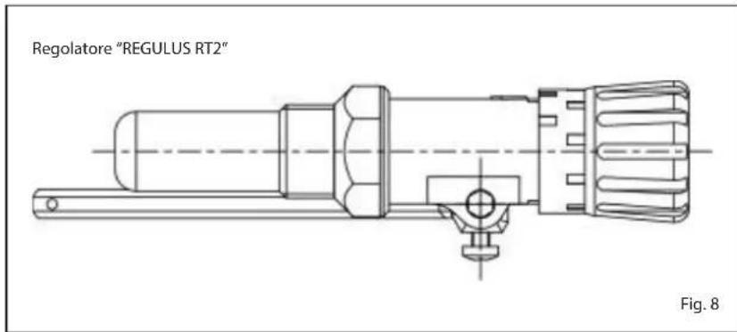
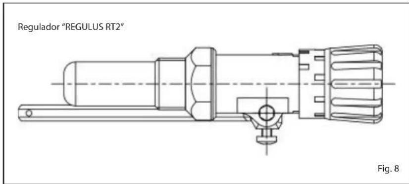
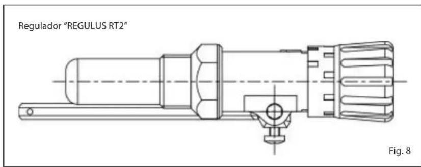
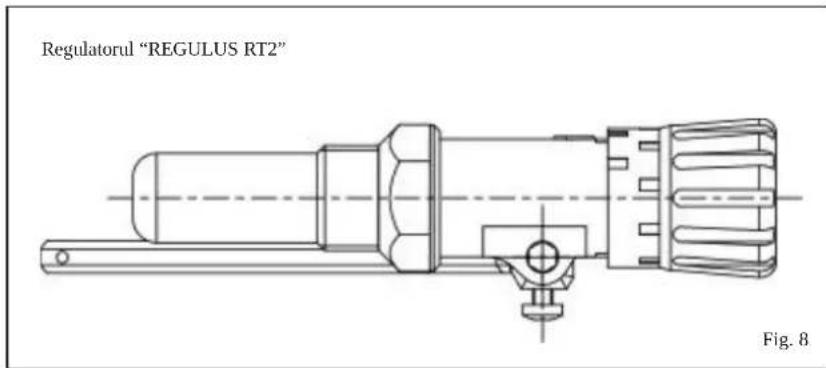
4.6.2 "REGULUS RT2" Regulator (fig. 8)
The adjustment field is included between 30 and 90°C (fig. 8). Follow the same instructions of the "Thermomat" regulator for the assembly and the activation.
4.7 SAFETY EXCHANGER
The safety exchanger is supplied upon request with a kit:
- code 8105200 for SOLIDA EV 3/4/5
- code 8105201 for SOLIDA EV 6/7.
The kit must be used on closed expansion tank systems with power lower than 35 kW. Its function is to cool the boiler in case of over-temperature, by using a thermal discharge valve connected to the exchanger inlet hydraulically.
In correspondence to the exchanger outlet, place one drainpipe with funnel and a siphon that drive to a suitable discharge.
The discharge must be visible for inspection.
ATTENTION: Failure to comply with this precaution, a possible activation of the thermal discharge valve can damage persons, animals and objects, which the manufacturer is not responsible for.
Before commissioning the boiler, ensure that the water flow of the thermal discharge valve is guaranteed.
4.8 HYDRAULIC CONNECTION DIAGRAMS
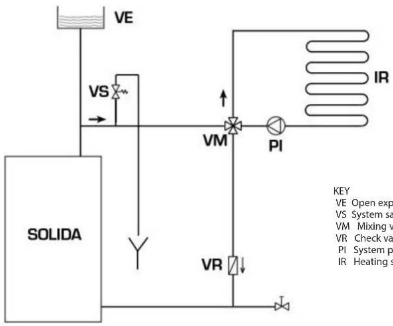
4.8.1 Open expansion tank system (fig. 9)
flowchart
graph TD
    A["VE"] --> B["VS"]
    B --> C["VM"]
    C --> D["PI"]
    D --> E["IR"]
    F["SOLIDA"] --> G["VR"]
    G --> H["Return Line"]
    style A fill:#f9f,stroke:#333
    style B fill:#ccf,stroke:#333
    style C fill:#cfc,stroke:#333
    style D fill:#fcc,stroke:#333
    style E fill:#cff,stroke:#333
    style F fill:#ffc,stroke:#333
    style G fill:#cfc,stroke:#333
    style H fill:#fcc,stroke:#333
KEY
VE Open expansion tank
VS System safety valve 3 BAR - 1/2"
VM Mixing valve
VR Check valve
PI System pump
IR Heating system
Fig. 9
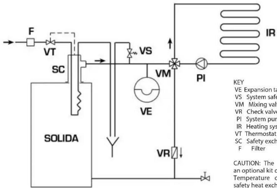
4.8.2 Closed expansion tank system and safety exchanger with thermostatic valve (fig. 10)
flowchart
graph TD
    A["SOLIDA"] --> B["VT"]
    B --> C["SC"]
    C --> D["VS"]
    D --> E["VM"]
    E --> F["PI"]
    F --> G["IR"]
    G --> H["HEATING SYSTEM"]
    H --> I["VA"]
    I --> J["VR"]
    J --> K["SO Box"]
    style A fill:#f9f,stroke:#333
    style B fill:#ccf,stroke:#333
    style C fill:#cfc,stroke:#333
    style D fill:#fcc,stroke:#333
    style E fill:#cff,stroke:#333
    style F fill:#ffc,stroke:#333
    style G fill:#fcf,stroke:#333
    style H fill:#cff,stroke:#333
    style I fill:#cfc,stroke:#333
    style J fill:#fcc,stroke:#333
    style K fill:#ffc,stroke:#333
KEY
VE Expansion tank
VS System safety valve 3 BAR - 1/2"
VM Mixing valve
VR Check valve
PI System pump
IR Heating system
VT Thermostat valve (97°C opening)
SC Safety exchanger
F Filter
CAUTION: The safety exchanger is supplied in an optional kit code 8105200/01.
Temperature of the water supplied to the safety heat exchanger: 10°C.
Pressure of the water supplied to the safety heat exchanger: 2 bar.
Assembly of the safety heat exchanger (SC) is mandatory.
Before commissioning the boiler, ensure that the water flow of the thermostatic valve is guaranteed (VT).
Fig. 10
5 USE AND MAINTENANCE
5.1 PRELIMINARY CHECKS BEFORE COMMISSIONING
Before commissioning the boiler, comply with the following instructions:
- The system connected to the boiler should be with open expansion tank system (fig. 9).
- The pipe connecting the boiler to the expansion tank must have a suitable diameter in compliance with the standards in force.
- The heating pump must always run during the boiler operation.
- The operation of the pump must never be interrupted by an environment thermostat.
- If the system is equipped with 3 or 4-way mixing valve, this must always be opened towards the system.
- Ensure that the draught regulator runs regularly and there are no obstructions that block the automatic operation of the air gate dumper.
5.2 BOILER THERMOMETER (fig. 11)
Indicates the temperature of the boiler wa-
ter (pos. 1).
5.3 AIR ADJUSTMENT (fig. 11)
The primary air is adjusted automatically by means of a thermostatic valve; on the other hand, the secondary air is adjusted by means of a round port placed on the upper side of the load port and must be adjusted by the user.
At the first start-up, the primary and secondary air must be adjusted, considering that the primary air determines the boiler power and, therefore, the amount of wood that is burnt and the secondary air completes the combustion.
The optimal regulation of the SOLIDA EV operation is reached when both the boiler and chimney will be "in temperature".
Depending on the wood used and its humidity, rotate the round port (anti-clockwise to open and clockwise to close) so to take the flame to optimal conditions: orange-pink-white with a blue centre.
CAUTION:
Secondary air regulator with high temperatures!
Use gloves or suitable equipment to not
get burned.
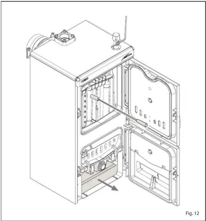
5.4 CLEANING (fig. 12)
Cleaning operations must be carried out frequently, by cleaning, besides the flue channels, also the ash-pit port, removing the ash in the collecting tray.
For cleaning the flue channels, use a specific scraper.
5.5 MAINTENANCE
Do not perform any maintenance work, dismantling or removal of parts without properly emptying the boiler first.
The boiler must not be emptied when the water is hot.
CAUTION: The safety valve on the system must be inspected by technically qualified personnel in accordance with the laws of the country of distribution and instructions for use of the safety valve.
If the system is completely emptied and remains unused for some time, the safety valve must be inspected before it is used again.
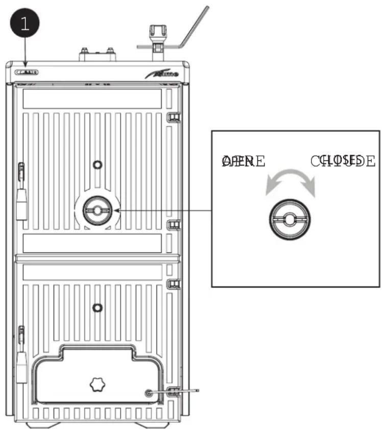
Fig. 11
If the safety valve should malfunction and cannot be re-calibrated, replace it with a new 1/2" valve calibrated to 3 BAR and conforming with Directive PED 2014/68/UE.
5.6 DISPOSAL OF THE EQUIPMENT
Once it reaches the end of its operating life, the equipment MUST BE RECYCLED in line with current legislation.
IT MUST NOT be disposed of together with urban waste.
It can be handed over to recycling centres, if there are any, or to retailers that offer this service.
Recycling prevents potential damage to the environment and health. It allows to recover a number of recyclable materials, with considerable savings in terms of money and energy.
natural_image
Technical line drawing of an open industrial machine with internal components and a directional arrow indicating motion (no text or symbols present)SUMAR
1 AVERTIZARI GENERALE 44
2 LIVRARE 44
3 CARACTERISTICI TEHNICE - DIMENSIUNI 45
3.1 DESCRIERE
3.2 DIMENSIUNI DE OCUPARE A SPATIULUI
3.3 DATE TEHNICE
3.4 PIERDERI DE SARCINA
4 INSTALARE 47
4.1 ÎNCAPEREA PENTRU MONTAREA CAZANULUI
4.2 RACORDAREA LA COSUL DE FUM
4.3 CONECTAREA INSTALATIEI
4.4 MONTAREA ACCESORIILOR
4.5 MONTAREA MANTALEI
4.6 REGULATORUL DE TIRAJ
4.7 SCHIMBATORUL TERMIC DE SIGURANTA
4.8 SCHEME DE RACORDARE LA INSTALATIA HIDRAULICA
5 UTILIZARE SI ÎNTRETINERE 51
5.1 VERIFICARI ÎNAINTE DE PUNEREA ÎN FUNCTIUNE
5.2 TERMOMETRUL CAZANULUI
5.3 REGLAREA CANTITATII DE AER
5.4 CURATARE
5.5 INTRETINERE
5.6 SCOATEREA DEFINITIVA DIN UZ A APARATULUI
1 AVERTIZARI GENERALE
natural_image
Technical line drawing of a mechanical device with internal components and mounting holes (no text or symbols)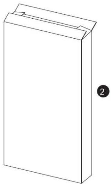
natural_image
Simple line drawing of a rectangular box with a lid, no text or symbols presentFig. 1
3 CARACTERISTICI TEHNICE - DIMENSIUNI
3.1 DESCRIERE
P putere cazan in kcal/h
4.6.1 Regulatorul "THERMOMAT RT-C" (fig. 7)
natural_image
Technical line drawing of an open industrial machine with internal components and a directional arrow indicating motion (no text or symbols)СОДЕРЖАНИЕ
natural_image
Technical line drawing of a mechanical device with internal components and mounting brackets (no text or symbols)
natural_image
Simple line drawing of a rectangular box with a folded top and side slot, labeled with number 2 (no text or symbols on the object itself)Илл. 1
ОБОЗНАЧЕНИЯ
natural_image
Technical line drawing of an open refrigerator with internal compartments and ventilation slots (no text or symbols)TABLES DES MATIÈRES
1 MISES EN GARDE GÉNÉRALES.... 64
2 FOURNITURE.... 64
3 CARACTÉRISTIQUES TECHNIQUES ET DIMENSIONS.... 65
3.1 DESCRIPTION
3.2 DIMENSIONS D'ENCOMBREMENT
3.3 CARACTÉRISTIQUES TECHNIQUES
3.4 PERTES DE CHARGE
4 INSTALLATION.... 67
natural_image
Technical line drawing of a mechanical device with internal components and mounting brackets (no text or symbols)
natural_image
Simple line drawing of a rectangular box with a cutout, labeled with number 2 (no text or symbols on the object itself)Fig. 1
3 CARACTÉRISTIQUES TECHNIQUES ET DIMENSIONS
3.1 DESCRIPTION
$$ S = \frac {Q}{1 0 0} $$
natural_image
Technical line drawing of an open industrial refrigerator with internal compartments and ventilation slots (no text or labels)Fig. 12
INHALTSVERZEICHNIS
1 ALLGEMEINE HINWEISE.... 74
2 LIEFERUMFANG 74
natural_image
Technical line drawing of a mechanical device with internal components and mounting holes (no text or symbols)
natural_image
Simple line drawing of a rectangular box with a folded top and a label '2' on the right side (no text or symbols on the box itself)Abb. 1
$$ S = \frac {Q}{1 0 0} $$
natural_image
Technical line drawing of an open industrial refrigerator with internal compartments and ventilation ducts (no text or symbols)KAZALO
1 SPLOŠNA OPOZORILA 84
2 DOBAVA 84
3 TEHNIČNE ZNAČILNOSTI IN VELIKOST 85
3.1 OPIS
3.2 VELIKOST
3.3 TEHNIČNE LASTNOSTI
3.4 IZGUBE TOVORA
4 INŠTALACIJA 87
4.1 PROSTOR ZA PEČ
4.2 PRIKLJUČITEV NA DIMNO CEV
4.3 PRIKLJUČITEV NAPELJAVE
4.4 MONTIRANJE DODATKOV
4.5 MONTIRANJE OHIŠJA
4.6 REGULATOR VLEKE NA TERMOSTATIČNO DELOVANJE
4.7 VARNOSTNI TOPLOTNI IZMENJEVALEC
4.8 NAČRTI ZA VODOVODNO POVEZAVO
5 UPORABA IN VZDRAEEVANJE.... 91
5.1 KONTROLA PRED VÄEIGOM
5.2 TERMOMETER KOTLA
5.3 URAVNAVANJE ZRAKA
5.4 ČIŠČENJE
5.5 VZDRŽEVANJE
5.6 ODLAGANJE NAPRAVE
1 SPLOŠNA OPOZORILA
natural_image
Technical line drawing of a mechanical device with internal components and mounting holes (no text or symbols)
natural_image
Simple line drawing of a rectangular box with a folded top and a label '2' on the right side (no text or symbols on the box itself)sl. 1
3 TEHNIČNE ZNAČILNOSTI IN VELIKOST
3.1 OPIS
Les je dragocen alternativni vir energije, zato je z njim treba kar najbolje ravnati in upora-
$$ S = \frac {Q}{1 0 0} $$
LEGENDA
1 Vijak z roEico M10 x 70
2 Matica z navojem
3 Vzvod M6
sl. 5/a
istem postopku.
Regulator "THERMOMAT RT-C"
sl. 7
Regulator "REGULUS RT2"
etiketo
4.6 REGULATOR VLEKA NA TERMOSTATIČNO DELOVANJE
4.6.1 Regulator "THERMOMAT" (sl. 7)
natural_image
Technical line drawing of an open industrial refrigerator with internal compartments and a directional arrow indicating movement (no text or symbols)5.6 ODLAGANJE NAPRAVE

- CARATTERISTICHE TECNICHE E DIMENSIONALI
- DESCRIZIONE
- MANUTENZIONE
- CARACTERÍSTICAS TÉCNICAS E DIMENSIONAIS
- DESCRICÃO
- ÍNDICE
- ESPECIFICACIONES TÉCNICAS Y DIMENSIONES
- DESCRIPCIÓN
- INDEX
- MAIN WARNINGS
- SUPPLY
- TECHNICAL AND DIMENSIONAL CHARACTERISTICS
- DESCRIPTION
- OVERALL DIMENSIONS (fig. 2)
- TECHNICAL DATA
- INSTALLATION
- BOILER ROOM
- Positioning in the power station (fig. 4)
- CONNECTION TO THE FLUE
- CONNECTION OF THE PLANT
- Filling the system
- Features of the feed water
- ASSEMBLING
- ASSEMBLING
- DRAUGHT REGULATOR WITH THERMOSTATIC OPERATION
- "THERMOMAT RT-C" Regulator (fig. 7)
- "REGULUS RT2" Regulator (fig. 8)
- SAFETY EXCHANGER
- HYDRAULIC CONNECTION DIAGRAMS
- Open expansion tank system (fig. 9)
- Closed expansion tank system and safety exchanger with thermostatic valve (fig. 10)
- USE AND MAINTENANCE
- PRELIMINARY CHECKS BEFORE COMMISSIONING
- BOILER THERMOMETER (fig. 11)
- AIR ADJUSTMENT (fig. 11)
- CAUTION:
- CLEANING (fig. 12)
- MAINTENANCE
- DISPOSAL OF THE EQUIPMENT
- SUMAR
- AVERTIZARI GENERALE
- CARACTERISTICI TEHNICE - DIMENSIUNI
- DESCRIERE
- СОДЕРЖАНИЕ
- ОБОЗНАЧЕНИЯ
- TABLES DES MATIÈRES
- CARACTÉRISTIQUES TECHNIQUES ET DIMENSIONS
- INHALTSVERZEICHNIS
- KAZALO
- SPLOŠNA OPOZORILA
- TEHNIČNE ZNAČILNOSTI IN VELIKOST
- OPIS
- Regulator "THERMOMAT RT-C"
- Regulator "REGULUS RT2"
- REGULATOR VLEKA NA TERMOSTATIČNO DELOVANJE
- Regulator "THERMOMAT" (sl. 7)
- ODLAGANJE NAPRAVE
Brand : SIME
Model : SOLIDA EV
Category : Camera