
B-Home Round 25 - Camera SIME - Free user manual and instructions
Find the device manual for free B-Home Round 25 SIME in PDF.


| Product Type | Smart Home Camera |
| Model | B-Home Round 25 |
| Brand | SIME |
| Dimensions | Diameter: 100 mm, Height: 50 mm |
| Weight | 200 g |
| Power Supply | 5V DC via USB cable (included) |
| Main Functions | Full HD video recording, night vision, motion detection, two-way audio, smartphone app control |
| Storage | MicroSD card (up to 128 GB) or cloud storage |
| Connectivity | Wi-Fi 2.4 GHz, Bluetooth 4.2 |
| Field of View | 120° diagonal |
| Installation | Indoor use, tabletop or wall mount |
| Care and Cleaning | Clean lens with a soft, dry cloth; avoid water and solvents |
| Safety | Do not expose to rain or moisture; use only supplied adapter |
| Spare Parts | Available via SIME customer service |
| Repairability | Refer to user manual for disassembly instructions |
| Environmental Conditions | Operating temperature: 0°C to 40°C; humidity: 20% to 80% |
| Warranty | 2 years |
Frequently Asked Questions - B-Home Round 25 SIME
User questions about B-Home Round 25 SIME
0 question about this device. Answer the ones you know or ask your own.
Ask a new question about this device
Download the instructions for your Camera in PDF format for free! Find your manual B-Home Round 25 - SIME and take your electronic device back in hand. On this page are published all the documents necessary for the use of your device. B-Home Round 25 by SIME.
USER MANUAL B-Home Round 25 SIME
B-Home Round 25 B-Essential Round 50
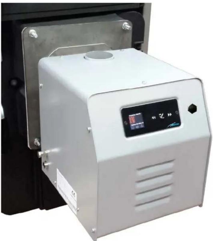
natural_image
Exterior view of a white industrial air purifier unit with control panel and metallic frame (no visible text or symbols)IT
ES
ENG
RUS
SL
1 BRUCIATORE A PELLET
1.1 Divieti
È VIETATO:
| A(mm) | B(mm) | C(mm) | D(mm) | E(ø mm) | Fmm | G(ø mm) | H(mm) | Peso(Kg) |
| 1760 190 | 1168 402 60 190 | 60 120 9 |
SCHEMA ELETTRICO
1 PANNELLO COMANDI
2 TASTI FUNZIONALI

1 PANEL DE MANDOS
2 TECLAS FUNCIONALES

Prow Pottemziadelloquereiator
- Do not use the appliance in areas with a potentially explosive atmosphere.
- Do not carry out modifications to the product without the written authorisation of the manufacturer.
- Do not open the door of the boiler when it is in use.
- Do not store inflammable materials close to the burner, to minimise the risk of fire.
- Do not leave the appliance exposed to the weather.
- Do not install the appliance onto heat generators (boilers, water heaters) situated in places which are poorly ventilated or are very damp. The vents in the building must be sufficiently large to guarantee complete combustion.
- Do not touch the appliance with parts of the body which are wet, or damp and/or with bare feet.
- The appliance must not be used by children or by people who are inexperienced.
1.2 Conformities
The burner B-Home Round 25 (code 8075980) and B-Essential Round 50 (code 8075981) conforms to European Directives:
- Machinery Directive 2006/42/CE
- Electromagnetic Compatibility Directive 2014/35/UE
- Low Voltage Directive 2014/30/UE
as stated in the Conformity Certificate supplied with the appliance.
1.3 Structure


1 Control Panel
2 Carter housing
3 Socket connection hose
4 Boiler connection flange
5 Washer
6 Combustion chamber
7 Arrangement for Room thermostat
8 Connection seven-pin plug (Safety thermostat/Air pressure switch/Door micro switch)
9 Boiler water probe connection
10 External cochlea motor connection
11 Manual pellet loading button
12 Fuse (3.15A delayed)
13 Main switch
14 Fuse (4A)
15 Power socket (230 volts)
16 External cochlea fan power socket
17 Connection for use with a PC
18 Flame detection photocell
19 Burner safely thermostat
20 Internal cochlea gear motor
21 Combustion air vent
22 Compressed air
combustion kit (OPTIONAL)
23 Internal cochlea
24 Display card
25 Electronic card
26 230V/24V transformer
27 Burner fan
28 Ignition resistance
29 Fuel grill
30 Dust protection ring
31 Room thermostat connection
cable

1.4 Burner description
The burner B-Home Round 25 (code 8075980) and B-Essential Round 50 (code 8075981) is an extremely versatile appliance and is able to cover a wide range of applications, from installation on new generation boilers, bread ovens or hot air generators to the transformation of old boilers
It is composed of a round combustion head, a main fan with variable speed regulation, a reliable ignition system thanks to the igniter and the flame detection photocell, an internal cochlea for fuel feeding and it is also designed for a compressed air self-cleaning system to be installed. It must be fitted with a fuel feeding system composed of a cochlea with a flexible connection pipe to the burner, and a pellet container, which is supplied separately as an accessory.
The burner and the whole plant are connected to a control panel with a microprocessor which is fitted onto the appliance and which controls all the other functions, as well as programming the time bands. This is really useful for the Operator, because it allows the appliance to be used only when needed.
1.5 Safety devices
The burner B-Home Round 25 (code 8075980) and B-Essential Round 50 (code 8075981) is fitted with the following safety devices:
- Burner safety thermostat
- Firebreak valve (cod. 6326916 - optional)
1.6 Size

| Model A | B | CDEFGHIL | M | N | ||||||||
| Round 25 | 47,5 mm | 140 mm | 101 mm | 263 mm | 22 mm | 60 mm | 232 mm | 272,5 mm | 249 mm | 30 mm | 21 mm | 543 mm |
| Round 50 | 33,5 mm | 168,5 mm | 77 mm | 263 mm | 17,5 mm | 60 mm | 232 mm | 272,5 mm | 249 mm | 30 mm | 21 mm | 543 mm |
1.7 Technical data
| Description | U/M | B-Home Round 25 (code 8075980) | B-Essential Round 50 (code 8075981) |
| Burner power | kW | 12 ÷ 30 | 12 ÷ 50 |
| Power supply | V - Hz | 230 - 50 | 230 - 50 |
| Average power consumption | W | 60 | 60 |
| Ignition | W | 230 | 230 |
| Fuse (delayed) | A | 3.15 | 3.15 |
| Noise level | dBA | 35 | 40 |
| Flame height | mm | 200 | 300 |
| Flue draw | Pa | 20 | 20 |
1.8 Feed cochlea

| A(mm) | B(mm) | C(mm) | D(mm) | E(ø mm) | Fmm | G(ø mm) | H(mm) | Weight(Kg) |
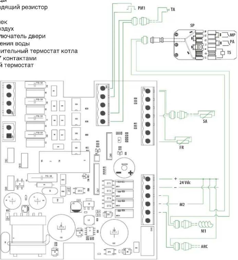
| 1760 190 | 1168 402 60 190 | 60 120 9 |
WIRING DIAGRAM
VPC Main combustion fan
VCE External cochlea fan
RS Resistance
PM1 External cochlea button
TE External thermostat
SA Water probe
FR Photoresistance
M1 External cochlea
M2 Internal cochlea
ARC Compressed air
MP Door micro switch
PA Air pressure switch
TS Safety thermostat
SP Seven-pin plug
TA Room thermostat
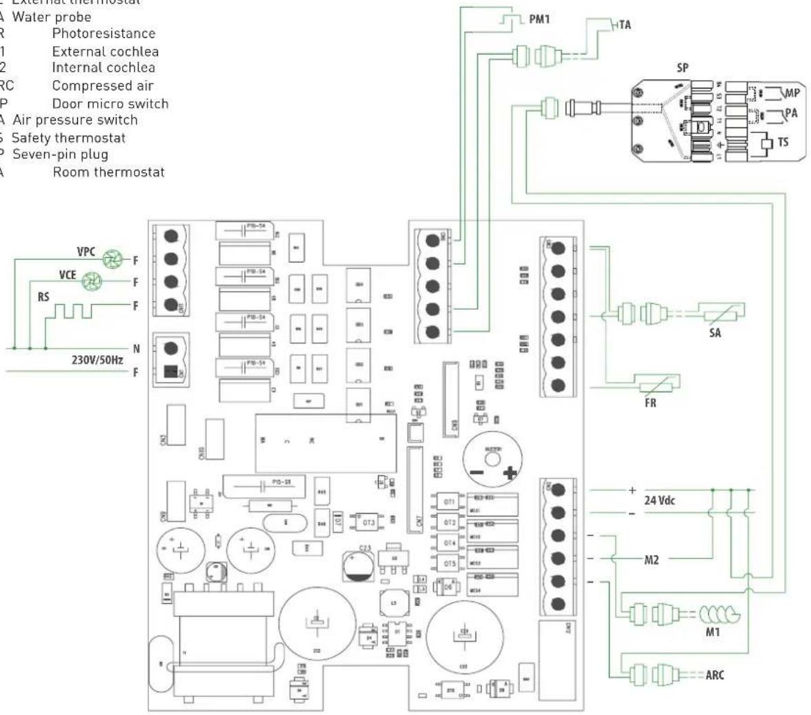
1,9 Running
The running of the appliance is controlled from a control panel with a microprocessor which programmes the following phases:
- When a request for heat is sent in start-up mode the main fan, the external cochlea and the internal loading cochlea start up to supply the necessary quantity of pellets for ignition. The internal cochlea starts up 8 seconds later than the external cochlea;
- When the pellet loading for ignition is finished, the ignition resistance is powered electrically, and this ignites the flame the brightness of which is recorded by the photocell within a max. of 20 minutes (safety time). In the event of non-ignition, the burner goes into SHUTDOWN mode. In the event of a SHUTDOWN, in order to reactivate normal running conditions, it is necessary to disconnect the appliance from the mains, remove the cause of the malfunction, and then reconnect it to the power supply;
- After the flame has been correctly detected, the appliance starts to run normally with a gradual increase in power supply until the maximum value programmed is reached, and the appliance continues to operate in modulation until the programmed water temperature for the boiler is reached, or that of a water storage heater if one is installed. While the burner is running, the external and internal cochleas also work according to the programmed ON and OFF times;
- Once the programmed temperature has been reached, the cochleas, both internal and external, are stopped by the control panel, and the pellets remaining in the combustion chamber continue to burn;
- When the brightness of the photocell goes below 20 lux, the fan speed increases to clear the combustion chamber of the last residue and then it stops.
The burner is then ready for the next start-up.
WARNING CAUTION
- The programming of the parameters MUST be carried out EXCLUSIVELY BY QUALIFIED TECHNICIANS AUTHORISED BY only after the Password has been given.
- For the working and shut-down periods of the burner, whether the "time bands" are activated or not should be taken into consideration.
- If the COMPRESSED AIR KIT is also present, cleaning of the combustion chamber takes place at the beginning and at the end of each operational cycle of the burner.
IT IS FORBIDDEN
Programming of the technical parameters from the User Menu.
1.10 Pellet
The appliance is designed and built to burn high-quality pellets which do not contain loose sawdust and that have the following characteristics:
| Description U/M | Pellet | |
| Diameter mm 6 DIN PLUS | ||
| Length mm 25 [max] | ||
| Density Kg/m | 3 | 650 |
| Lower heating power kWh/kg 5 | ||
| Percentage of humidity | % | max 8 (of the weight) |
| Percentage of ash | % | max 1 (of the weight) |
1.11 Control Panel

1 CONTROL PANEL
2 OPERATING KEYS

Pressure SHORT (1 second): Access to User Menu
Pressure LONG (>2 seconds): Check of programmed data
Pressure LONG (>12 seconds): Reset of all parameters. WARNING!!! With this operation, all previous programming will be erased (*).

Pressure SHORT (1 second): Modification of power
Pressure LONG (>2 seconds): Ignition/shut-down of burner

Pressure SHORT (1 second): Temperature modification
Pressure LONG (>2 seconds): Access to Installer's Menu. To gain access it is necessary to know the password (*).
3 SCREEN
A Date
B Burner state
C Time
D Parameters
E Power consumed
F Boiler water temperature
(*) Actions only to be taken by AUTHORISED INSTALLERS.
Viewings on Screen
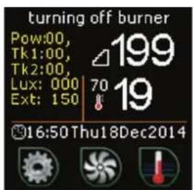
Power Burner power
Tk1 Loading time of external cochlea (SI)
Tk2 (NOT USED)
Lux Brightness intensity
Ext Fan speed of external supply cochlea
WARNING: At the base of many screens shows "indications guide" very useful to the operator.
1.12 User parameters

flowchart
graph TD
    A["Main display"] --> B["To enter "LANGUAGE""]
    B --> C["To enter "TIME""]
    C --> D["HOUR FORMAT"]
    D --> E["DATE"]
    E --> F["To enter burner power levels (1-2-3-4-5)"]
    F --> G["To enter boiler water temperature (10-90°C)"]

    B --> H["ON/OFF → (*)"]
    C --> I["ON/OFF → (*)"]
    D --> J["ON/OFF → (*)"]
    E --> K["ON/OFF → (*)"]
    F --> L["ON/OFF → (*)"]

    H --> M["TEMPERATURE"]
    I --> N["BRIGHTNESS"]
    J --> O["ENABLE TIMER"]
    K --> P["WEEKLY TIMER"]
    L --> Q["TYPE OF FUEL"]
    M --> R["ON/OFF → (*)"]
    N --> S["ON/OFF → (*)"]
    O --> T["ON/OFF → (*)"]
    P --> U["ON/OFF → (*)"]
    Q --> V["ON/OFF → (*)"]
    R --> W["ON/OFF → (*)"]
    S --> X["ON/OFF → (*)"]
    T --> Y["ON/OFF → (*)"]
    U --> Z["ON/OFF → (*)"]
    V --> AA["ON/OFF → (*)"]
(*) To enter User Parameter programming (see paragraph "Programming of user parameters".
2 START-UP
2.1 Before starting up the burner
Before starting up the appliance check that:
- the burner is correctly mounted on the boiler door and that this latter is firmly closed
– the cochlea and the burner flexible connection hose are positioned correctly - the pellet container has been filled
– the water temperature probe has been correctly positioned
– the boiler and the plant has been filled with water
– the hydraulic circuit valves are open - the fumes exhaust duct has been set up properly.
2.2 First ignition
Connect the burner power supply, positioning the plant main switch and the main burner switch in the "ON" position, and check that the screen lights up.
The burner leaves the factory calibrated to approximately 20 kW. Before igniting the burner for the first time, change the parameters as detailed under point 2.7.1.
To ignite it for the first time, press the ON-OFF button and hold for approximately 2 seconds, then wait for the flame to light.
Leave the burner in the continuous running mode, at maximum power for about 15 minutes, and then with a flue gas analyser check that the values recorded are close to the ones indicated in the table:
| Description U/M | Correct value | |
| O2 % ~ 10 | ||
| CO [average] mg/cm | 3 | < 500 |
| Exhaust temperature °C 120 ÷ 200 |
Press the √ON √OFF key to turn off the burner and leave it to cool.
WARNING: This operation must be carried out ONLY by authorised and qualified technicians.
2.3 Checks to carry out after the first ignition
After the first ignition, with a cold burner:
– disconnect the pellet supply tube from the burner
- open the boiler door and check that on the combustion chamber grill THERE IS NO unburnt material. If this is not the case, it is necessary to modify the settings on the basis of the specific needs (the combustion air and the quantity of fuel) and to repeat the "FIRST IGNITION" phase previously described.
2.4 Automatic shut-down and subsequent start-ups
Once the heat demand has been satisfied the supply of pellets is stopped, and the burner adapts its speed in order to burn the residual pellets present in the combustion chamber, until the minimum brightness level (20 Lux) appears, which is recorded by the photocell. When 20 lux is reached, the fan speeds up to maximum velocity (for 4 minutes) in order to clean the combustion chamber of any residue and then stops. At every request for heat all the phases described previously are repeated.
2.5 Pellet calibration
The calibration of the quantity of pellets necessary for ignition and for running the burner is achieved as follows:
- fill the pellet container
- pull out the flexible hose from the burner socket and place it in a recipient (basin)
- Check that there are no requests for heat
- Connect the burner power supply, positioning the plant main switch and the main burner switch in the "ON" position, and check that the screen lights up
- press the button (manual loading) until the pellets are falling continuously into the recipient (the cochlea is full of pellets)
- empty the recipient and press the button again (manual loading) for about 6 seconds (loading time for max power 5), controlling the time with a stopwatch, and weigh the pellets which have fallen into the basin.
Calculate the burner power using the following formula: [Y/X * 3.6] * Z = kW where:
Y Quantity of pellets (in grams) weighed in 6 seconds (loading time for max power)
X Load intervals (time between each pellet load)
3,6 Fixed value
Z Pellet lower heating value
The calculated value will serve as a reference for setting the seconds for loading as performed by the external screw pump at power 5.
WARNING CAUTION: If the type of pellets being used is changed (not advisable) the calibration of the pellets MUST be repeated, because the combustion characteristics will change.
2.6 Programming of user parameters
The programming of the user parameters can be done following the flow diagram above, after connecting the burner to the mains.

flowchart
graph TD
    A["Main display"] --> B["To confirm selection and go back to Main Display"]
    B --> C["To enter "LANGUAGE" ON/OFF"]
    C --> D["To confirm selection ON/OFF"]
    D --> E["To select EN - IT - ES - FR - DE ON/OFF"]
    E --> F["To enter "TIME" ON/OFF"]
    F --> G["View current time ON/OFF"]
    G --> H["To programme or modify time ON/OFF"]
    H --> I["24/03/2015 ON/OFF"]
    I --> J["To programme or modify date ON/OFF"]
    J --> K["“HOUR FORMAT” ON/OFF"]
    K --> L["View 12 or 24 hours format ON/OFF"]
    L --> M["To select 12 or 24 hours ON/OFF"]
    M --> N["“DATE” ON/OFF"]
    N --> O["View month ON/OFF"]
    O --> P["To select current month ON/OFF"]
    P --> Q["To confirm setting and to move to day setting ON/OFF"]
    Q --> R["To programme or modify current day ON/OFF"]
    R --> S["To confirm setting and to move to year setting ON/OFF"]
    S --> T["To programme or modify year ON/OFF"]
    T --> U[""TEMPERATURE" ON/OFF"]
    U --> V["View F° or C° ON/OFF"]
    V --> W["To select F° or C° ON/OFF"]
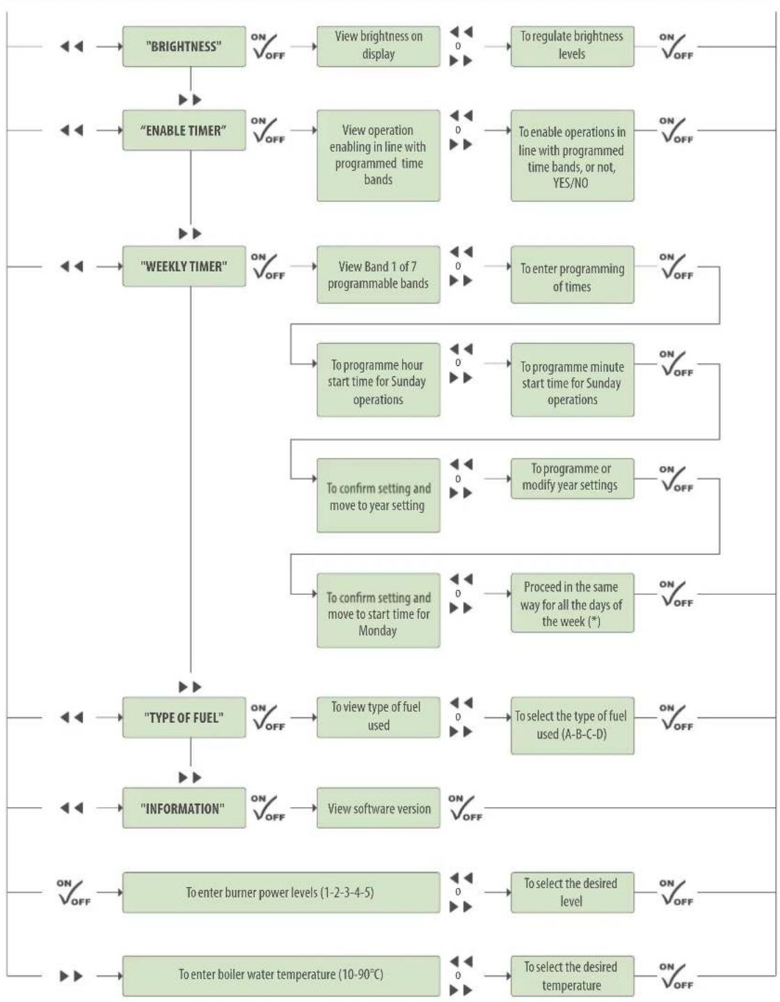
flowchart
graph TD
    A["BRIGHTNESS"] -->|ON/OFF| B["View brightness on display"]
    B -->|0| C["To regulate brightness levels"]
    C -->|ON/OFF| D["Output"]
    E["ENABLE TIMER"] -->|ON/OFF| F["View operation enabling in line with programmed time bands"]
    F -->|0| G["To enable operations in line with programmed time bands, or not, YES/NO"]
    G -->|ON/OFF| H["Output"]
    I["WEEKLY TIMER"] -->|ON/OFF| J["View Band 1 of 7 programmable bands"]
    J -->|0| K["To enter programming of times"]
    K -->|ON/OFF| L["Output"]
    M["TYPE OF FUEL"] -->|ON/OFF| N["To view type of fuel used"]
    N -->|0| O["To select the type of fuel used (A-B-C-D)"]
    O -->|ON/OFF| P["Output"]
    Q["INFORMATION"] -->|ON/OFF| R["View software version"]
    R -->|ON/OFF| S["Output"]
    T["To enter burner power levels (1-2-3-4-5)"] -->|ON/OFF| U["To select the desired level"]
    U -->|ON/OFF| V["Output"]
    W["To enter boiler water temperature (10-90°C)"] -->|ON/OFF| X["To select the desired temperature"]
    X -->|ON/OFF| Y["Output"]
(*)
1 When the Saturday times have been programmed, press the key √OFF to save the programmed times and to prepare for programming the Band 2 times
2 Press the key ▶▶ to select Band 2. Press the Key to confirm √OFF and enter the level for programming the start and end of running times
3 To programme the times, proceed as described above
4 Repeat the same procedure to programme the times of all the available time bands (up to 7)
To prevent the burner working in a particular time band, programme both the start time and the end time at 00.00.
2.7 List of parameters (Technical parameters)
| Viewing of screen | Description | U/M | Field | Factory default setting |
| TECHNICAL | ||||
| Δ temp. - | Hysteresis for water regulation temperature. When the set temperature is reached, the burner shuts off. If the temperature of the hysteresis value programmed falls below the set value, the burner starts up again. | °C 2 ÷ 30 2 | ||
| Δ temp. + | Maximum value the water temperature can reach beyond the set value. If the temperature exceeds the set value of the amount selected (5°C) the burner shuts off and only starts up again when the temperature programmed in the temperature control parameter is reached "Δ temperature ceck". | °C 1 ÷ 5 | 5 | |
| Enabling of 2nd pellet container Enables the use of 2nd pellet container. | On / Off | Off | ||
| External thermostat | Enables the use of an external thermostat (e.g. TA or TB). | On / Off | Off | |
| Viewing on display h2o | Enables viewing on the screen of the temperature programmed for the water in the boiler. | On / Off | On | |
| 110V / 60Hz | To be activated in the countries with this mains voltage. | YES / NO | NO | |
| IGNITION | ||||
| Pellet pre-loading (s) | This parameter sets the first pellet loading time. | sec | 0.0 ÷ 60.0 | 10 |
| Compressed air (s) | Duration of cleaning process with compressed air. | sec | 0.0 ÷ 20.0 | 6,00 |
| Initial ventilation | Fan intensity in the ignition phase after the "pellet pre-loading" phase ("precarico pellet"). | rpm | 0 ÷ 300 | 160 |
| Minimum lux start-up | Minimum brightness to establish a regular ignition. | Lux | 0 ÷ 1000 | 60 |
| Lux shut-down | If the brightness goes below the level recorded during the time regulated within the Dead Band parameter ("Banda Morta"), the burner shuts down. If this happens during normal running of the appliance, the signal ERROR appears on the display. | Lux | 0 ÷ 100 | 20 |
| Dead band (s) | This is the time during which the optical sensor must continuously record a value higher than the parameter "Minimum lux start- up" ("Lux minimo avvio"). Every time the values recorded go below the parameter Minimum lux start- up ("Lux minimo avvio"), the count starts up again. | sec | 0 ÷ 600 | 60 |
| Flame stabilisation (m) | Time deemed necessary for stabilisation of the flame, after which the burner is enabled to start up. | min | 0 ÷ 20 1 | |
| POWER LEVELS | ||||
| Type | Type of combustion being used. | A-B-C-D | A | |
| Fuel supply interval. | Time between one pellet reloading and the next. | Sec. | 1.0 ÷ 90.0 | 45.0 |
| Start-up | Filling Time from external cochlea to start. | Sec | 0.0 ÷ 30.0 | 3,0 |
| Fan | Fan speed at start. | rpm | 0 ÷ 300 | 220 |
| Power 1 | Filling Time from external cochlea to Power 1. | Sec | 0.0 ÷ 60.0 | 2,0 |
| Fan | Fan speed at Power 1. | rpm | 0 ÷ 300 | 150 |
| Power 2 | Filling Time from external cochlea to Power 2. | Sec | 0.0 ÷ 60.0 | 3,5 |
| Fan | Fan speed at Power 2. | rpm | 0 ÷ 300 | 160 |
| Power 3 | Filling Time from external cochlea to Power 3. | Sec | 0.0 ÷ 60.0 | 4,5 |
| Fan | Fan speed at Power 3. | rpm | 0 ÷ 300 | 170 |
| Power 4 | Filling Time from external cochlea to Power 4. | Sec | 0.0 ÷ 60.0 | 5,5 |
| Fan | Fan speed at Power 4. | rpm | 0 ÷ 300 | 180 |
| Power 5 | Filling Time from external cochlea to Power 5. | Sec | 0.0 ÷ 60.0 | 6,5 |
| Fan | Fan speed at Power 5. | rpm | 0 ÷ 300 | 200 |
| NOTAThe fill-up time depends on the power level programmed and on the type of fuel being usedThe fan speed depends on the fuel (type and quantity) and on the flue draw | ||||
| CLEANING | ||||
| Cleaning intervals (m) | The interval between the cleaning of the combustion grill carried out by the burner fan and the cleaning carried out with compressed air. | min | 0 ÷ 300 | 60 |
| Grill cleaning (s) | Duration of cleaning process with burner fan running at maximum power. | sec | 1 ÷ 180 | 30 |
| Fan cleaning | Fan speed during cleaning phase. | rpm | 0 ÷ 300 | 300 |
| Compressed air | Presence of compressed air kit (optional). | YES / NO | NO | |
| External fan | Speed of cochlea fan. | rpm | 0 ÷ 300 | 300 |
| Shutting down | ||||
| Duration | The time during which the ventilator goes on running at max. power when the burner has been shut down due to an alarm going off. The objective is to burn all the residual fuel left on the grill. This cycle is activated when the burner is off. | min | 0 ÷ 20 2 | |
| Ventilation | Fan speed during shut-down phase. | rpm | 0 ÷ 300 | 300 |
| External thermostat. | This determines the operational mode of the burner once the environment set value programmed has been reached. | min | 0 ÷ 90 0 | |
| PAGE - TEST | ||||
| Resistance Start-up / Shut-down | Ignition resistance | ON/OFF | OFF | |
| Air Start-up / Shut-down | Activates 24V electrovalve power supply for the compressed air kit | ON/OFF | OFF | |
| Alarm Start-up / Shut-down | Activates the 230V output | ON/OFF | OFF | |
| Cochlea Shut-down | Internal cochlea | ON/OFF | OFF | |
| Tank shut-down | External cochlea | ON/OFF | OFF | |
| Internal Fan | Burner fan | rpm | 0 ÷ 300 | |
| External Fan | Cochlea fan | rpm | 0 ÷ 300 | |
| NOTAThis checks that the main components of the burner are working correctly | ||||
| REMOTE CONTROL | ||||
| Module | Must be activated to connect the GSM module to connector 6 on the burner | YES / NO | NO | |
2.7.1 Approved calibration
| Viewing of screen D | escription U/M F | ield | Approved calibration | ||
| Round 25 | Round 50 | ||||
| Power 1 | Filling Time from external cochlea to Power 1. | Sec | 0,0 ÷ 60,0 | 2,0 | 2,5 |
| Fan | Fan speed at Power 1. | rpm | 0 ÷ 300 | 110 | 160 |
| Power 2 | Filling Time from external cochlea to Power 2. | Sec | 0,0 ÷ 60,0 | 2,8 | 4,3 |
| Fan | Fan speed at Power 2. | rpm | 0 ÷ 300 | 120 | 185 |
| Power 3 | Filling Time from external cochlea to Power 3. | Sec | 0,0 ÷ 60,0 | 3,7 | 6,2 |
| Fan | Fan speed at Power 3. | rpm | 0 ÷ 300 | 130 | 210 |
| Power 4 | Filling Time from external cochlea to Power 4. | Sec | 0,0 ÷ 60,0 | 4,6 | 7,3 |
| Fan | Fan speed at Power 4. | rpm | 0 ÷ 300 | 140 | 225 |
| Power 5 | Filling Time from external cochlea to Power 5. | Sec | 0,0 ÷ 60,0 | 5,5 | 8,5 |
| Fan | Fan speed at Power 5. | rpm | 0 ÷ 300 | 150 | 240 |
| NOTAThe fill-up time depends on the power level programmed and on the type of fuel being usedThe fan speed depends on the fuel (type and quantity) and on the flue draw | |||||
2.7.2 Alarm messages
In the event of a fault or malfunction, the following signs appear on the screen:
| Description |
| Failed ignition |
| Blackout alarm |
| Faulty water probe alarm |
| Fuel finished alarm |
| TS overheating |
| Fuel finished |
2.7.3 Problems - Possible causes - Solutions
In the table below are reported the most common problems with their possible solutions.
| Problem | Possible cause | Solution |
| Failed ignition | Empty pellet container | Fill the container |
| Disconnected or broken external cochlea cable | Reconnect the cable or find the break | |
| Ignition resistance broken | Check the resistance and/or substitute it | |
| Combuston grill is blocked | Pull out the grill and clean it | |
| Internal cochlea blocked | Check the internal cochlea and remove any blockages | |
| Power supply absent | Electrical supply to burner not present | Check the mains supply |
| Check that the electrical cables are connected correctly | ||
| Check that the general switches and the switches on the burner are in the correct position | ||
| Water probe | The probe is incorrectly positioned or connected | Check its position and connections |
| Probe faulty | Replace the probe | |
| Fuel finished | Pellet container empty | Fill the container |
| Disconnected or broken cochlea cable | Re-establish the connection | |
| Cochlea motor not working | Check the motor |
3 MAINTENANCE
3.1 Periodic maintenance
Periodic maintenance, as well as being necessary for the optimal functioning of the burner and the plant, is required by Law and if maintenance regulations are not observed, there can be problems or even fines.
Maintenance must be entrusted to and carried out SOLELY by qualified technicians.
The pellet burner B-Home Round 25 (code 8075980) and B-Essential Round 50 (code 8075981) was designed to require minimal maintenance, the frequency of which depends directly on the quality and size of the pellets used (certified or not) and on adjustments made to the settings.
WARNING DANGER ELECTRICITY
Before carrying out any maintenance activity, disconnect the appliance from the mains, and put the general switches on the plant into the OFF position, but also the main ones on the burner and the boiler (if present).
WARNING CAUTION
- When carrying our maintenance, all the Personal Safety Equipment required by current Legislation must be used.
- Periodic maintenance refers to the whole plant in which the burner is installed.
- If non-certified pellets are used, the indications below are rendered null and void, since the characteristics of the fuel are not known.
- In the event of the use of non-certified pellets, Fonderie Sime S.p.A. DOES NOT ACCEPT RESPONSIBILITY for any breakages or malfunctions or for any possible harm to people, animals or things, or to the environment.
- The table is only for suggestion purposes and is not binding.
- For cleaning the housing of the burner, use a damp cloth with water and soap or water and methylated spirits, or with specific non-abrasive products.
| Periodic When necessary | Weekly Six-monthly Annual | ||
| BURNER CLEANING | |||
| Combustion chamber - ash and slag x x | |||
| Burner fan x x | |||
| Internal cochlea Photocell Ignition resistance | x | x | |
| Pellet container Filling | x x | ||
| Combustion air suction grill | x x | ||
| External cochlea bearings Possible greasing or lubrication | x | ||
| External cochlea fan | x | ||
| Control of perishable parts | x x | ||
| Control of cables and electrical connections | x | x | |
| PLANT CLEANING | |||
| Smoke channel and flue pipe | x x | ||
| Inside and back part of the boiler | x x | ||
| Control of perishable parts | x x | ||
| Control of exhaust fumes | x x |
1 ПАНЕЛЬ УПРАВЛЕНИЯ
| Model A | B | CDEFGHIL | M | N | ||||||||
| Round 25 | 47,5 mm | 140 mm | 101 mm | 263 mm | 22 mm | 60 mm | 232 mm | 272,5 mm | 249 mm | 30 mm | 21 mm | 543 mm |
| Round 50 | 33,5 mm | 168,5 mm | 77 mm | 263 mm | 17,5 mm | 60 mm | 232 mm | 272,5 mm | 249 mm | 30 mm | 21 mm | 543 mm |
1 PLOŠČA ZA UPRAVLJANJE
2 FUNKCIJSKE TIPKE

Dotik KRATKO (1 sekundo): vstop v meni za uporabnika
Pow Močgorilnika
natural_image
Exterior view of a beige industrial machine with a white hose and control panel (no visible text or symbols)SOLIDA 5 PL cod. 8058541
Kit pellet Sime 5 PL cod. 8075980 (optional)
SOLIDA 8 PL + cod. 8075743
Kit pellet Sime 8 PL + cod. 8075981 (optional)
IT
ENG
RUS
ES
SL
INDICE
natural_image
Technical line drawing of a mechanical component with a folded edge (no text or symbols)natural_image
Close-up of hands cleaning a metal surface with a curved tool (no text or symbols visible)natural_image
Technical line drawing of a mechanical bracket with a curved handle and a separate curved component above it (no text or symbols)natural_image
Close-up of gloved hands installing or adjusting a metal component with a meshed surface (no visible text or symbols)natural_image
Technical line drawing of a mechanical assembly with a bracket and base plate (no text or symbols)natural_image
Close-up of a car's front door showing two stacked concrete blocks with visible wear and dust (no text or symbols)natural_image
Close-up of a hand using gloves to clean or repair vehicle material inside a vehicle (no visible text or symbols)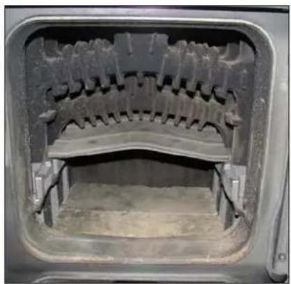
natural_image
Interior view of a mechanical or industrial component with a curved, mesh-like structure inside a rectangular frame (no visible text or symbols)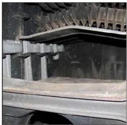
natural_image
Close-up of a mechanical component with metallic brackets and textured surfaces (no visible text or symbols)natural_image
Close-up of a mechanical component with a brass fitting inserted into a black cylindrical shaft, mounted on a white panel (no visible text or symbols)Mod. 200-300 dm²

1CB M5x12 [54 x)

TCB M6x5 [2 x]

TCB 7SPx3/8" (6 x)

TSP M5x20 |8 x|
Mod. 500 dm 3

108 M5x12 [66 x]

10B M6x8 (2 x)

TCB 7SPx3/8" |6 x1

TSP M5x20 (8 x)
![Tiranti solo per contenitore da 500 dm³ 8 x [200-300 dm²] 10 x [500 dm²] 4 x [200-300 dm²] 6 x [500 dm²] 8 x [200-300 dm²] 10 x (500 dm²) 4 x [200-300 dm²] 6 x [500 dm²] 4 x [200-300 dm²] 8 x [200-300 dm²] 10 x (500 dm²)](/content/2026/05/1091250/images/236b9eceb3d3ae3448a7178da0c13f6957e86bcdb0fbb8ec9a60580e66bd800f.jpg)

natural_image
Metallic rectangular object placed on a reflective surface with circular patterns, no visible text or symbols.Fig. 11 Inserimento coclea
natural_image
Back panel of an electronic device showing ports, connectors, and a 220V AC input (no readable text or symbols beyond labels)natural_image
Close-up of a black electrical plug inserted into a wall, with a yellow wire and label '7' pointing to it (no readable text or symbols beyond the label)natural_image
Hand holding a blue tool inside a white appliance with a brass component (no visible text or symbols)Fig. 14 Sonda mandata Fig. 15 Sonda mandata
natural_image
Close-up of a car engine component with a blue wire and numbered label (9), no readable text or symbols beyond the number.natural_image
Close-up of a black electrical socket with a yellow and black tool inserted, mounted on a metal frame (no visible text or symbols)Fig. 20
natural_image
Close-up of a door handle with a label 'A' and an arrow pointing to a clip, no readable text or symbols present.Cassetto
estraibile

natural_image
Line drawing of an open refrigerator with internal compartments and a handle (no text or symbols)
Fig. 19
1 OPERATION WITH PELLETS AND SPECIAL KIT 78
2 INSTALLATION 79
SOLIDA 5 PL code 8058541
Kit pellet Sime 5 PL code 8075980 (optional)
SOLIDA 8 PL + code 8075743
Kit pellet Sime 8 PL + cod. 8075981 (optional)
WARNINGS
- In case of failure or malfunction of the equipment, contact authorised technical staff
- Make sure that no external electrical cables can come into contact with hot parts of the water heater
- Duly install a device in the electrical power supply grid that ensures complete omni-polar disconnection (surge category III)
- During operation of the water heater, the fumes exhaust pipe and the cast iron doors reach high temperatures (do not touch without appropriate protection)
- If the electrical power supply cable is damaged, it must be replaced by the manufacturer or by qualified technical staff
- To avoid system water backflow, install check valves or valves that are only opened to reintegrate water into the system.
GENERAL NOTES
- The appliance must be installed by qualified staff who operate in compliance with the national standards in force and with the instructions in the accompanying manual.
- The appliance is not intended for use by persons, including children, with reduced physical, sensory or mental abilities. Children must be monitored to ensure they do not play with the appliance.
- A puffer (inertial accumulation) is recommended but not obligatory. Its presence has the advantage of releasing the water heater from the system's "sudden" requests and allowing integration with other sources of heat. Reduces consumption and increases system efficiency.
- Do not use or leave materials that are explosive or easily flammable (e.g. petrol, paint, paper) in the room where the appliance is installed.
- The user must be instructed on use and operation of the equipment.
1 OPERATION WITH PELLETS AND SPECIAL KIT
1.1 DESCRIPTION
The SOLIDA PL boilers may be transformed to operate with pellets. Accessory kit containing:
To maximize use of the product, we recommend the use of pellets with a quality
that is certified by an authorized body (the quality of the pellets used with the SOLIDA PL are defined in accordance with the DIN plus standard).
The boiler complies with Class 3 in accordance with EN 303-5/2012.
1.1.1 OVERALL DIMENSIONS (with pellets kit code 8079580 for SOLIDA 5 PL /code 8075981 for SOLIDA 8 PL+)
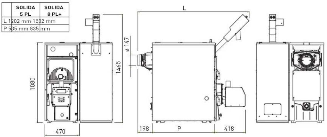
Fig. 1
1.1.2 TECHNICAL FEATURES (Kit with pellet)
| Model | SOLIDA 5 PL | SOLIDA 8 PL + | |
| Nominal thermal output | kW | 26.2 | 40.0 |
| Minimum thermal output | kW | 7.4 | 12.0 |
| Nominal heat input | kW | 34.7 | 50.0 |
| Minimum heat input | kW | 10.4 | 15.0 |
| Maximum useful efficiency | % | 75.96 | 80.00 |
| Minimum useful efficiency | % | 72.81 | 80.00 |
| CO mg/Nm 3 at 10% of O 2 at the nominal thermal input | 837.8 | 28.0 | |
| CO mg/Nm 3 at 10% of O 2 at the minimum thermal input | 467.3 | 1451.0 | |
| OGC mg/Nm 3 at 10% of O 2 at the nominal thermal input | 10.0 | 7.2 | |
| OGC mg/Nm 3 at 10% of O 2 at the minimum thermal input | 90.7 | 25.5 | |
| DUST mg/Nm 3 at 10% of O 2 at the nominal thermal input | 42.0 | 13.4 | |
| DUST mg/Nm 3 at 10% of O 2 at the minimum thermal input | - | 22.2 | |
| C.H. flow/return fittings | ø | 2" | 2" |
| Fumes flow-rate at nominal/minimum power | Kg/s | 0,0171/0,0104 | 0,0188/0,0111 |
| Max/min operating pressure | Mpa | 0,15/0,05 | 0,15/0,05 |
| Water content | L | 31 | 43 |
| Weight | Kg | 270 | 375 |
| Size of a pellet container with a capacity of 200 dm | H | 1081 | 1081 |
| L | 440 | 440 | |
| Size of a pellet container with a capacity of 300 dm | H | 1381 | 1381 |
| L | 440 | 440 | |
| Size of a container with a capacity of 500 dm a | H | 1481 | 1481 |
| L | 640 | 640 | |
2 INSTALLATION
2.1 MOUNTING ACCESSORIES SUPPLIED SEPARATELY
A) Place the cast iron 1st deflector with the rear side supports

natural_image
Technical line drawing of a mechanical component with a flanged top and a small bracket (no text or symbols)Fig. 2 Rear side supports Fig. 3 1

natural_image
Close-up of hands using a tool to clean or store metal surfaces (no visible text or symbols)51 deflector with the rear side supports
B) Place the cast iron 2nd deflector with the front side supports
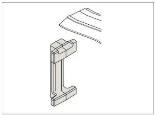
natural_image
Technical line drawing of a mechanical bracket with a curved handle and a separate view of its tip (no text or symbols)Fig. 4 Front side supports Fig. 5 2

natural_image
Close-up of gloved hands installing or adjusting a metal component with visible teeth and wear (no text or symbols)nd deflector with the front side supports
C) Place the remaining front lateral supports and insert the cement bricks

natural_image
Technical line drawing of a mechanical assembly with a bracket and base plate (no text or symbols)Fig. 6 Lateral supports Fig. 7 Cement bricks

natural_image
Close-up of a vehicle's door frame showing a concrete block inside, with no visible text or symbols.WARNING!
THE CEMENT BRICKS MUST BE ADJACENT TO THE FRONT PART OF THE BOILER
D) Place the last cast iron deflector

natural_image
Close-up of a person in gloves handling a car tire component (no visible text or symbols)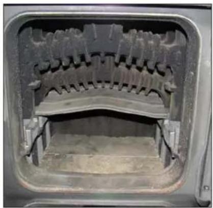
natural_image
Interior view of a mechanical device with a curved, meshed component and no visible text or symbols
natural_image
Close-up of a vehicle's front wheel and side railings, showing structural components (no visible text or symbols)Fig. 8 Last deflector
E) Screw the brass reduction by interposing the sealant for the hydraulic seal
F) Screw the safety thermostat to the reduction

natural_image
Close-up of a car door with a brass connector inserted, showing no visible text or symbols.Fig. 9 Safety thermostat
CAUTION:
Screw the thermostat by hand or with a fork spanner: tightening torque of 1.5 Nm
natural_image
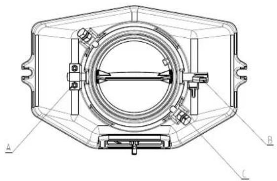
Technical line drawing of a mechanical component with labeled parts A, B, and C (no text or symbols beyond labels)Fig. 10 Flue gas damper
WARNING:
When installing a pellet boiler, the flue gas damper must be open.
To prevent the damper from closing unintentionally, lock it in place by tightening nut "A" or attaching a tie rod between points "B" and "C".
G) Assembly pellets tank (200 to 500 dm³) positioned to the right of the boiler, resting on the flank and aligned at the same.

Mod. 200-300 dm 3
TCB M5x12 (54 x)
TCB M6×5 |2 x|
TCB 7SPx3/8" (6 x)
TSP M5x20 18 x1
TCB M5x12 |66 x|
TCB M6x8(2 x)
TCB 7SPx3/B* |6 x|
TSP M5x2018 x)
Mod. 500 dm 2
![Only for pellets tank 500 dm³ 8 x [200-300 dm²] 10 x [500 dm²] 4 x [200-300 dm²] 6 x [500 dm²] 4 x [200-300 dm²] 6 x [500 dm²] 8 x [200-300 dm²] 10 x [500 dm²] 4 x [200-300 dm²] 6 x [500 dm²] 4 x [200-300 dm²] 8 x [200-300 dm²] 10 x [500 dm²]](/content/2026/05/1091250/images/ab3da86b37182499d7bec4963e2d04d98e696740a44a9001dc0d68af7d399441.jpg)

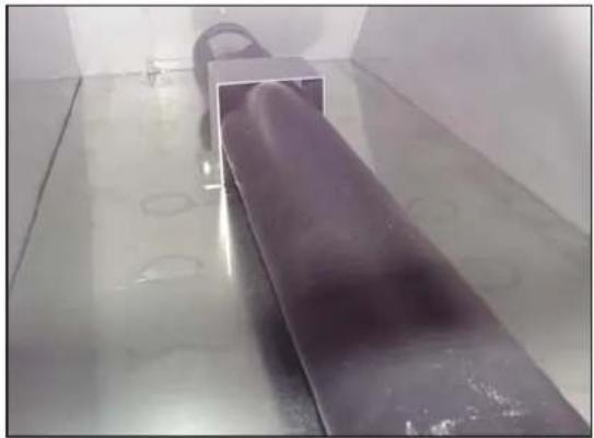
H) Push the cochlea feeder motor in its housing container pellets.
natural_image
Interior view of a large metallic cylindrical object with reflective surface, placed on a reflective floor (no visible text or symbols)Fig. 11 - Insertion cochlea
1) Mounting the burner (B-Home Round 25 for SOLIDA 5 PL and B-Essential Round 50 for SOLIDA 8 PL+).
Position the seal (4), supplied with the burner, between the flange (5) and the door (2) of the boiler
Push in the 4 screws [6] (M8) but ONLY tighten the two screws which hold the lower split-flange. The two screws of the upper split-flange must ONLY BE PLACED but not tightened.
Insert the combustion chamber of the burner into the boiler as far as is necessary (see close-up A)
Tighten the two semi-flanges with the screws (7) and the screws (6), which were previously just placed in position.
WARNING DANGER
The burner MUST be mounted ONLY in the position shown in the diagram. Any other position is FORBIDDEN.
The flame will propagate in a straight line, through the hole of the burner combustion chamber.

2.2 ELECTRICAL CONNECTIONS
A) Connect the cable connector coming from the screw feeder motor to the burner (3 fig. 12)
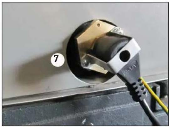
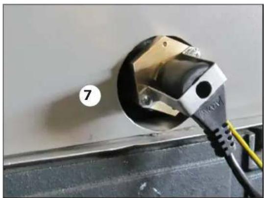
B) Connect the safety thermostat connector (7 fig. 13) the seven-pin plug (see WIRING DIAGRAM)

natural_image
Back panel of an electronic device showing ports, connectors, and wiring (no readable text or symbols)Fig. 12 Screw feeder motor cable

natural_image
Close-up of a black electrical plug inserted into a wall, with a yellow cable and label '7' pointing to it (no text or symbols on the plug itself)Fig. 13 Safety thermostat connector
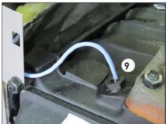
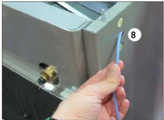
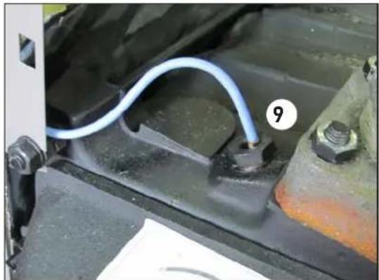
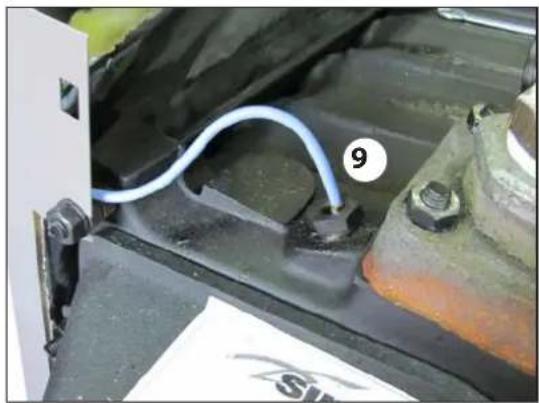
C) Place the inlet joint (8 fig. 14) in the sheath (9 fig. 15) found on the boiler body
natural_image
Close-up of a hand holding a blue tool near a white appliance with a numbered label (8) on the door (no readable text or symbols)Fig. 14 Inlet joint Fig. 15 Inlet joint
natural_image
Close-up of a car's battery panel with a blue wire and numbered component (9), no visible text or symbols on the main subject.D) Connect the burner power cable to the mains (1 fig. 16).

Fig. 16 Connection to the mains
BLUE = NEUTRAL BROWN = PHASE YELLOW-GREEN = EARTH
1 Power supply socket [230V-50Hz]
2 External cochlea fan power socket
3 External cochlea motor
4 Boiler water temperature probe
5 Connection seven-pin plug
(Safety thermostat / Air pressure switch / Door micro switch)
6 Connection for use with a PC
7 Connection to room thermostat
2.3 WIRING DIAGRAM
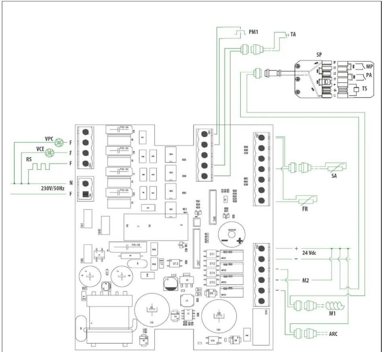
VPC Main combustion valve
VCE External cochlea fan
RS Resistance
PM1 External cochlea button
TE External thermostat
SA Water probe
FR Photoresistance
M1 External cochlea
M2 Internal cochlea
ARC Compressed air
MP Door micro switch
PA Air pressure switch
TS Safety thermostat
SP Seven-pin plug
TA Room thermostat
Fig. 17
2.4 HYDRAULIC DIAGRAM
The hydraulic circuit must be set up by an authorised installer or qualified personnel in compliance with the design specifications and the technical standards and legislation in force. The temperature of the return water of the water heater should always be above 55irc C. An anti-condensation unit MUST, therefore, be installed, otherwise the warranty is rendered null and void.
WARNING
- The components of the system are the responsibility of the installer, who must observe the legislation in force and release a declaration of conformity upon completion of his work.
- SIME cannot be held liable for harm to people or animals or damage to property attributable to an incorrect choice of components or improper set-up of the system.
The hydraulic circuit diagram that can be used as a valid reference.

flowchart
graph TD
    E["Material E"] --> B["Component B"]
    B --> 4["Valve 4"]
    B --> 5["Valve 5"]
    B --> 2["Valve 2"]
    B --> 5["Valve 5"]
    B --> 7["Valve 7"]
    B --> 5["Valve 5"]
    B --> 9["Valve 9"]
    B --> 5["Valve 5"]
    B --> 13["Valve 13"]
    7 --> 12["Valve 12"]
    7 --> 11["Valve 11"]
    13 --> A["Processing Unit A"]
    12 --> A
    11 --> A
    5 --> EAF["EAF"]
    6 --> EAF
    8 --> EAF
    5 --> EAF
    10 --> EAF
    style A fill:#f9f,stroke:#333
    style EAF fill:#ccf,stroke:#333
LEGEND
A Pellet heater
B Puffer
C Anti-condensation unit
D Filling and emptying of the water heater/system
E Heating system/DHW
EAF Cold water inlet
1 Reverse-acting anti-condensation thermostat (50°C)
2 Control thermostat to be connected to the TE terminal block
4 Automatic relief valve
5 Ball valve
6 Pressure regulator
7 Anti-condensation mixing valve
8 Filter
9 Circulation pump
10 Filling and discharge valve
11 Safety valve (2.5 bar minimum)
12 Pressure gauge
13 Expansion vessel
NOTE: It is advisable to use an open vessel system.
Fig. 18
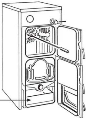
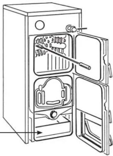
2.5 CLEANING (fig. 19)
Cleaning operations must be carried out at regular intervals and only when the boiler is cold.
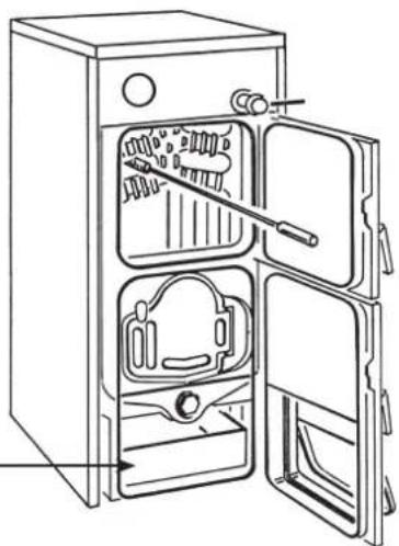
Combustion residuals collect in the removable drawer that must be emptied before starting the boiler.
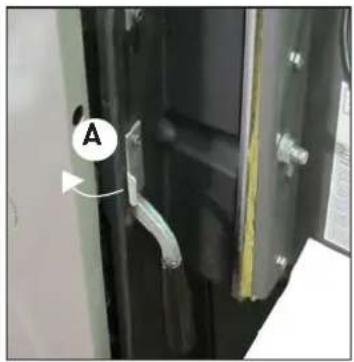
ATTENTION: To release and open the bottom door, lift the locking bracket (A).
To remove all combustion residuals, use an ordinary aspirator and verify that all the ashes inside the combustion chamber have been completely removed.
The aspirator can also be used to clean the fuel grille.
To clean the fume ducts inside the boiler body, use a wiper.
ATTENTION: if the generator is switched off for long periods of time (above 15 days), it is necessary to empty the pellet container in order to prevent the pellets from absorbing excessive humidity, which could affect the operation of the boiler. A high amount of humidity in the pellets could cause them to pulverize, increase the amount of residuals in the brazier and obstruct the pellet feeding system.
2.6 SAFETY THERMOSTAT (fig. 20)
The safety thermostat with manual reset intervenes automatically, switching off the burner, when the water heater temperature exceeds 95°C.
To start the water heater back up again, press the button as shown in the figure. During the resetting procedure one must not remove the bracket that protects the thermostat.
If this event occurs frequently, have qualified staff inspect the equipment.

natural_image
Close-up of a metal electrical socket mounted on a wall, with wires and a yellow tool inserted (no visible text or symbols)Fig. 20
2.7 ANNUAL MAINTENENCE
For optimum performance, it is advisable to have the boiler inspected accurately and thoroughly by qualified personnel at least once every season.

Removable drawer
natural_image
Line drawing of an open refrigerator with internal compartments and a handle (no text or symbols)
Fig. 19
Before performing maintenance operations, verify that the boiler is cold and has been disconnected from the mains.
2.7.1 Warnings
In the event of product failure and/or malfunction, switch it off and do not attempt to repair or intervene on it.
Any repairs must be carried out by authorised staff using original spare parts.
2.8 DEMOLITION AND DISPOSAL OF THE APPLIANCE (2012/19/UE)

At the end of its life cycle the appliance MUST BE DISPOSED AND
RECYCLED, as required by current law.
It MUST NOT be disposed of with domestic waste. It can be taken
to waste recycling centres, where they exist, or to a dealer providing this service.
Recycling waste prevents potential damage to the environment and harm to health. It also allows you to recover many recyclable materials with significant economic and energy savings.
2.9 ACCESSORIES
The available accessories to be ordered separately:
- code 5197500 200-litre PELLET TANK (1081 x 440)
- code 5197510 300-litre PELLET TANK (1381 x 440)
- code 5197520 500-litre PELLET TANK (1481 x 640)
natural_image
Technical line drawing of a mechanical component with a separate view (no text or symbols)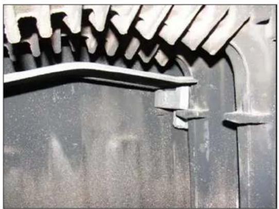
natural_image
Close-up of a metallic mechanical component with a curved bracket and flange (no visible text or symbols)natural_image
Technical line drawing of a mechanical bracket with a curved handle (no text or symbols)
natural_image
Close-up of gloved hands installing or adjusting a metal component with a meshed edge (no visible text or symbols)natural_image
Technical line drawing of a mechanical assembly with a bracket and base plate (no text or symbols)
natural_image
Close-up of a car's front wheel with visible friction and insulation layers (no text or symbols)natural_image
Close-up of a person in gloves handling a car tire component (no visible text or symbols)
natural_image
Interior view of a mechanical device with internal gear-like components (no visible text or symbols)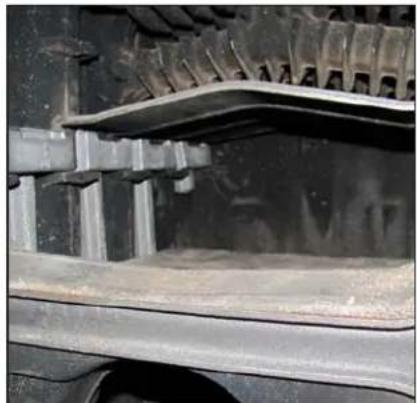
natural_image
Close-up of a mechanical component with metallic brackets and a curved surface (no visible text or symbols)natural_image
Close-up of a white wall-mounted device with a metallic knob and a black handle inserted, no visible text or symbols.natural_image
Technical line drawing of a mechanical component with labeled parts A, B, and C (no text or symbols beyond labels)Мод. 500 дм³
Мод. 200-300 дм 2

1CB M5x12 [54 x)

108 M5x12 [66 x]

1CB MaxB [2 x]

10B M6x8 (2 x)

TCB 7SPx3/8" (6 x)

TCB 7SPx3/8" |6 x1

TSP M5x2D |8 x|

TSP M5x20 (8 x)


natural_image
Interior view of a metallic industrial or laboratory chamber with a rectangular duct and pipe, no visible text or symbols.Рис. 11 - Введение
I) Монтаж горелки (В-Home Round 25 для SOLIDA 5 PL и B-Essential Round 50 для SOLIDA 8 PL+) .
natural_image
Back panel of an electronic device showing ports, connectors, and a 220V AC input (no readable text or symbols beyond labels)
natural_image
Close-up of a black electrical outlet plug with a yellow cable, no visible text or symbolsnatural_image
Hand holding a blue tool inside a refrigerator with a numbered label (8) on the door (no visible text or symbols on the device itself)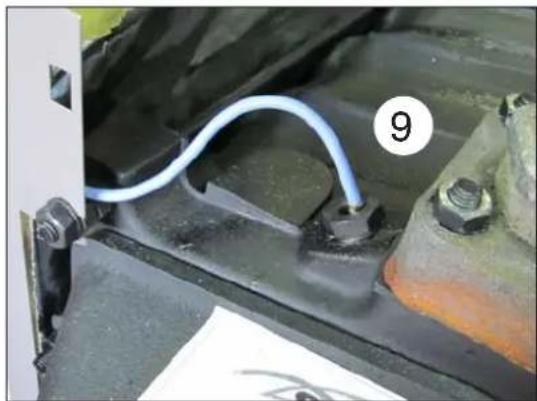
natural_image
Close-up of a blue cable being inserted into a car engine compartment, with no visible text or symbols.natural_image
Close-up of a black electrical socket with yellow wires and a yellow bulb inserted, mounted on a metal surface (no text or symbols visible)Рис. 20
natural_image
Close-up of a door panel with a labeled component 'A' and a tool, no readable text or symbols present.Выдвижной
Ящик
natural_image
Line drawing of an open refrigerator with internal compartments and doors (no text or symbols)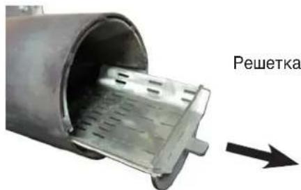
natural_image
Technical line drawing of a mechanical component with a flanged top and a separate clamped part (no text or symbols)natural_image
Close-up of hands cleaning a metal pipe with a curved pipe and clamped components (no visible text or symbols)natural_image
Technical line drawing of a mechanical bracket with a curved handle and base plate (no text or symbols)natural_image
Close-up of gloved hands adjusting a metal component with visible teeth and wear (no text or symbols)natural_image
Technical line drawing of a mechanical assembly with a bracket and base plate (no text or symbols)natural_image
Close-up of a car interior showing two stacked concrete blocks with visible wear and dust (no text or symbols)natural_image
Close-up of a person's hand using gloves to clean or repair a vehicle interior (no visible text or symbols)
natural_image
Interior view of a mechanical component with internal cavities and mounting brackets (no visible text or symbols)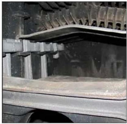
natural_image
Close-up of a vehicle's roof structure showing asphalt and asphalt layers (no text or symbols visible)Fig. 8 Último deflector
natural_image
Close-up of a mechanical pipe fitting with a brass fitting inserted into a black circular opening, mounted on a metal frame (no text or symbols visible)natural_image
Technical line drawing of a mechanical component with labeled parts A, B, and C (no text or symbols beyond labels)Mod. 200-300 dm²

1CB M5x12 [54 x)

TCB M6x5 [2 x]

TCB 7SPx3/8" (6 x)

TSP M5x20 |8 x|
Mod. 500 dm 3

108 M5x12 [66 x]

10B M6x8 (2 x)

TCB 7SPx3/8" |6 x1

TSP M5x20 (8 x)
![Espaciador solo para contenedor de 500 dm³ 8 x [200-300 dm²] 10 x [500 dm²] 4 x [200-300 dm²] 6 x [500 dm²] 4 x [200-300 dm²] 8 x [200-300 dm²] 10 x (500 dm²) 4 x 5 x 6 x 7 8 x 9 10 x 11 x 12 x 13 x 14 x 15 x 16 x 17 x 18 x 19 x 20 x 21 x 22 x 23 x 24 x 25 x 26 x 27 x 28 x 29 x 30 x 31 x 32 x 33 x 34 x 35 x 36 x 37 x 38 x 39 x 40 x 41 x 42 x 43 x 44 x 45 x 46 x 47 x 48 x 49 x 50 x](/content/2026/05/1091250/images/7a9d0d0f9759743cbdd9e980f472f0cfa283490b0b92acc58773749998bd1cf5.jpg)

natural_image
Metallic cylindrical object placed on a reflective surface with circular patterns (no text or symbols visible)natural_image
Back panel of an electronic device showing ports, connectors, and a 220V AC input (no text or symbols on components)Fig. 12 Cable del motor del tornillo sin fin
natural_image
Close-up of a black electrical plug inserted into a wall, with a yellow wire and label '7' pointing to it (no readable text or symbols beyond the label)natural_image
Hand holding a blue tool near a white appliance with a brass fitting (no visible text or symbols)natural_image
Close-up of a car engine component with a blue wire and numbered label (9), no readable text or symbols beyond the number.natural_image
Close-up of a screwdriver inserted into a wall socket, with wires and a yellow tool visible (no text or symbols)Fig. 20
natural_image
Close-up of a door handle with a label 'A' and an arrow pointing to a clip (no readable text or symbols)Cajón extraíble
natural_image
Line drawing of an open refrigerator with internal compartments and a handle (no text or symbols)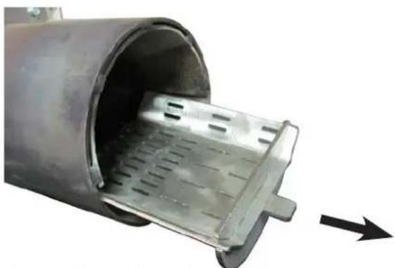
natural_image
Close-up of a metallic cylindrical device with internal perforated structure and an arrow indicating direction (no text or symbols)Rejilla del combustible
Fig. 19
2.7 MANTENIMIENTO ANUAL
natural_image
Technical line drawing of a connector with a small inset showing internal structure (no text or symbols)Sl. 2 nosilci zadaj ob straneh

natural_image
Close-up of hands cleaning a metal pipe with visible cracks and dust (no text or symbols)natural_image
Technical line drawing of a mechanical bracket component with a curved handle attachment (no text or symbols)Sl. 4 nosilci spredaj ob straneh

natural_image
Close-up of a gloved hand adjusting a metal component with visible teeth and wear (no text or symbols)natural_image
Technical line drawing of a mechanical assembly with a bracket and base plate (no text or symbols)natural_image
Close-up of a car interior showing two stacked concrete blocks with visible wear and insulation (no text or symbols)POZOR!
BETONSKE PLOŠČE SE MORAJO PRILEGATI K PREDNJI STRANI PEČI
natural_image
Close-up of a hand using a tool to adjust or repair vehicle components on a vehicle (no visible text or symbols)
natural_image
Interior view of a mechanical or electrical enclosure with internal structural components (no visible text or symbols)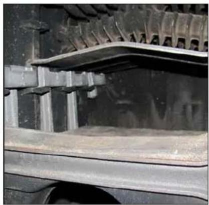
natural_image
Close-up of a vehicle's track and tracks with visible tracks and structural elements (no text or symbols)natural_image
Close-up of a mechanical component with a metallic blade and brass fitting, mounted on a white panel (no visible text or symbols)natural_image
Technical line drawing of a mechanical component with labeled parts A, B, and C (no text or symbols beyond labels)natural_image
Close-up of a metallic rod partially submerged in a transparent container, with no visible text or symbols.Sl. 10 Vstavitev
I) Montaža gorilnika (B-Home Round 25 za SOLIDA 5 PL in B-Essential Round 50 za SOLIDA 8 PL+).
Tesnilo (4), ki je priloženo gorilniku, namestite med prirobnico (5) in vrata (2) kotla Namestite 4 vijake (6) (M8) a privijte LE vijaka, ki pritrjujeta vmesno spodnjo polprirobnico. Vijaka zgornje polprirobnice LE NAMESTITE, a ju še ne privijte
natural_image
Back panel of an electronic device showing ports, connectors, and wiring (no readable text or symbols)Sl. 11 Kabel motorja polža
natural_image
Close-up of a black electrical socket with a yellow wire inserted, mounted on a metal surface (no text or symbols visible)Sl. 12 Konektor varnostnega termostata
C) Senzor temperature vode (8 Sl. 13) vstavite v brezno (9 Sl. 14) v ohišju kotla

natural_image
Close-up of a hand holding a blue tool near a white car with 'F500' branding (no visible text or symbols on the tool itself)Sl. 13 Senzor temperature vode v potisni vod
natural_image
Close-up of a car's battery panel with a blue wire and numbered component (9), no visible text or symbolsSl. 14 Senzor temperature vode v potisni vod
D) Vtičnici gorilnika priključite omrežno električno napajanje (1 SI. 15).

natural_image
Close-up of a wall socket with a yellow tool inserted, showing wiring and a black plastic component (no text or symbols visible)Sl. 19
2.7 LETNO VZDRŽEVANJE
natural_image
Close-up of a metallic cylindrical device with internal perforated structure, showing internal flow direction (no text or symbols)

- B-Home Round 25 B-Essential Round 50
- BRUCIATORE A PELLET
- Divieti
- È VIETATO:
- SCHEMA ELETTRICO
- Conformities
- Structure
- Burner description
- Safety devices
- Size
- Technical data
- WIRING DIAGRAM
- 1,9 Running
- WARNING CAUTION
- IT IS FORBIDDEN
- Pellet
- Control Panel
- CONTROL PANEL
- OPERATING KEYS
- SCREEN
- Viewings on Screen
- START-UP
- Before starting up the burner
- First ignition
- Checks to carry out after the first ignition
- Automatic shut-down and subsequent start-ups
- Pellet calibration
- Programming of user parameters
- Approved calibration
- Alarm messages
- Problems - Possible causes - Solutions
- MAINTENANCE
- Periodic maintenance
- WARNING DANGER ELECTRICITY
- INDICE
- WARNINGS
- GENERAL NOTES
- OPERATION WITH PELLETS AND SPECIAL KIT
- DESCRIPTION
- OVERALL DIMENSIONS (with pellets kit code 8079580 for SOLIDA 5 PL /code 8075981 for SOLIDA 8 PL+)
- TECHNICAL FEATURES (Kit with pellet)
- INSTALLATION
- MOUNTING ACCESSORIES SUPPLIED SEPARATELY
- WARNING!
- CAUTION:
- WARNING:
- WARNING DANGER
- ELECTRICAL CONNECTIONS
- HYDRAULIC DIAGRAM
- WARNING
- LEGEND
- CLEANING (fig. 19)
- ATTENTION: To release and open the bottom door, lift the locking bracket (A).
- SAFETY THERMOSTAT (fig. 20)
- ANNUAL MAINTENENCE
- Warnings
- DEMOLITION AND DISPOSAL OF THE APPLIANCE (2012/19/UE)
- ACCESSORIES
- MANTENIMIENTO ANUAL
- LETNO VZDRŽEVANJE
Brand : SIME
Model : B-Home Round 25
Category : Camera