SKSPH3602S - Fan SIGNATURE - Free user manual and instructions
Find the device manual for free SKSPH3602S SIGNATURE in PDF.

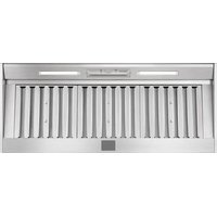
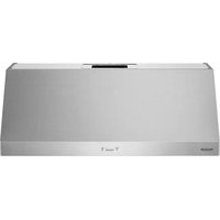
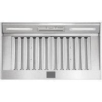
| Product Type | Range Hood (Hood Ventilator) |
| Brand | Signature Kitchen Suite |
| Model | SKSPH3602S |
| Width (Nominal) | 36 in (91.4 cm) |
| Weight | 60 lb (27.2 kg) |
| Power Supply | 120 V~, 60 Hz, 4 A |
| Number of Speeds | 5 |
| Maximum CFM (Adjustable) | 600 (390 or 290 depending on setting) |
| Filter Type | Baffle, dishwasher-safe |
| Number of Filters | 3 |
| Lighting | 8 W LED strip |
| Control Type | Touch |
| Duct Diameter | 8 in round or 3-1/4 x 10 in rectangular |
| Recommended Mounting Height | 26 to 36 in (66 to 91.4 cm) above cooking surface |
| Duct Material | Rigid metal only |
| Motor Protection | Thermal overload with automatic shut-off and restart |
| Installation Type | Under cabinet |
Frequently Asked Questions - SKSPH3602S SIGNATURE
User questions about SKSPH3602S SIGNATURE
0 question about this device. Answer the ones you know or ask your own.
Ask a new question about this device
Download the instructions for your Fan in PDF format for free! Find your manual SKSPH3602S - SIGNATURE and take your electronic device back in hand. On this page are published all the documents necessary for the use of your device. SKSPH3602S by SIGNATURE.
USER MANUAL SKSPH3602S SIGNATURE
Read these instructions thoroughly before installing and operating the hood.
SKSPH3602S
SKSPH4802S

MFL70208703_05
www.signaturekitchensuite.com
Copyright © 2017 - 2024 Signature Kitchen Suite. All Rights Reserved.
2 TABLE OF CONTENTS
TABLE OF CONTENTS
3 BEFORE YOU BEGIN
4 IMPORTANT SAFETY INSTRUCTIONS
7 PRODUCT SPECIFICATIONS
7 General Specifications
7 Adjusting Maximum CFM Level
8 Checking Max CFM Level
9 Dimensions
10 PRODUCT OVERVIEW
10 Parts
10 Accessories
11 PLANNING THE INSTALLATION
11 Cabinet Layout
12 Ducting Options
13 Ducting Calculation Sheet
14 Power Supply
14 Verify the Package Contents
15 INSTALLATION INSTRUCTIONS
15 Rotating the Blower
17 Mounting the Range Hood
18 WIRING DIAGRAM


BEFORE YOU BEGIN
IMPORTANT:
• Installer: In the interest of safety and to minimize problems, read these installation instructions completely and carefully before you begin the installation process. Leave these installation instructions with the customer.
- Customer: Keep these installation instructions for future reference and the local electrical inspector's use.
APPLIANCE DATA PLATE
- The appliance data plate contains the model and serial number information and the electrical requirements.
- It is located inside the hood behind the filters on the back side of the chassis. Remove the filters to view it.
All specifications subject to change without notice. SIGNATURE KITCHEN SUITE assumes no liability for changes to specifications.
IMPORTANT SAFETY INSTRUCTIONS
Read and follow all instructions when using the range to prevent the risk of fire, electric shock, personal injury, or damage. This guide does not cover all possible conditions that may occur. Always contact your service agent or manufacturer about problems that you do not understand.
Download this owner's manual at: www.signaturekitchensuite.com

This is the safety alert symbol. This symbol alerts you to potential hazards that can result in property damage and/or serious bodily harm or death.
All safety messages will follow the safety alert symbol and either the word WARNING or CAUTION. These words mean:

WARNING - Indicates a hazardous situation which, if not avoided, could result in death or serious injury.

CAUTION - Indicates a hazardous situation which, if not avoided, could result in minor or moderate injury.

WARNING
- To avoid the possibility of explosion or fire, do not store or use combustible, flammable or explosive vapors and liquids (such as gasoline) inside or in the vicinity of this or any other appliance. Also keep items that could explode, such as aerosol cans away from cooktop burners, ovens and range hoods. Do not store flammable or explosive materials in adjacent cabinets or areas.
- If the information in this manual is not followed exactly, a fire or explosion may result causing property damage, personal injury or death.
- Do not use an additional speed control device with this unit.
- To avoid motor bearing damage and noisy and/or unbalanced impellers, keep drywall spray, construction dust, etc. off power unit.
- Your ventilator motor has a thermal overload which will automatically shut off the motor if it becomes overheated. The motor will restart when it cools down. If the motor continues to shut off and restart, have the product serviced.
- NOT SUITABLE FOR USE WITH SOLID-STATE SPEED CONTROLS.
• TO REDUCE THE RISK OF FIRE, ELECTRIC SHOCK, OR INJURY TO PERSONS, OBSERVE THE FOLLOWING:
– Use this unit only in the manner intended by the manufacturer. If you have questions, contact the manufacturer.
– Before servicing or cleaning unit, switch power off at service panel and lock the electrical panel door to prevent power from being switched on accidentally. When the electrical panel door cannot be locked, securely fasten a prominent warning device, such as a tag, to the service panel.

WARNING
• TO REDUCE THE RISK OF FIRE, ELECTRIC SHOCK, OR INJURY TO PERSONS, OBSERVE THE FOLLOWING:
- Installation work and electrical wiring must be done by qualified person(s) in accordance with all applicable codes and standards, including fire-rated construction. - Sufficient air is needed for proper combustion and exhausting of gases through the flue(chimney) of fuel burning equipment to prevent back drafting. Follow the heating equipment manufacturer's guidelines and safety standards such as those published by the National Fire Protection Association (NFPA), and the American Society for Heating, Refrigeration and Air Conditioning Engineers (ASHRAE), and the local code authorities.
- When cutting or drilling into wall or ceiling, do not damage electrical wiring and other hidden utilities.
– Ducted fans must always be vented to the outdoors.

CAUTION
For general ventilating use only. Do not use to exhaust hazardous or explosive materials and vapors.
GENERAL SAFETY PRECAUTIONS
To reduce the risk of fire, electric shock, serious injury or death when using the appliance, follow basic safety precautions, including the following:

WARNING
- Do not install or operate this hood if it has been damaged, dropped, has damaged electrical wires or is not working properly. If the product is damaged when received, immediately contact the dealer or builder.
- This range hood must be installed and grounded by a qualified installer according to these installation instructions.
- Install or locate this appliance only in accordance with these installation instructions and the requirements specified by the manufacturer of the cooktop or range. Improper installation, adjustment, alteration, service or maintenance can cause serious personal injury or property damage.
- The customer should not install, repair or replace any part of the range hood unless specifically recommended in the literature accompanying it. A qualified service technician should perform all other service.
- Keep all packaging materials away from children. Plastic bags can cause suffocation.
- Do not use an extension cord or adapter plug with this appliance.
- The installer must show the customer the location of the fuse box or circuit breaker panel box so that the customer knows where and how to turn the power off.
- Before installing or servicing the range hood, switch power off at the fuse box circuit breaker and lock the electrical panel door to prevent power from being switched on accidentally. When the electrical panel cannot be locked, securely fasten a prominent warning device, such as a tag, to the electrical panel.
- Read the owner's manual completely before using the appliance. Clean the appliance only as instructed in the owner's manual. Use only the cleaners specified.
- Do not tamper with the controls.

WARNING
- Never allow the filter(s) to become blocked or clogged. Do not allow foreign objects, such as cigarettes or napkins, to be sucked into the hood.
- Clean the filter(s) and all grease-laden surfaces often to prevent grease fires and maintain performance.
- If the cooktop and range hood are near a window, use an appropriate window treatment. Avoid long drapes or other window coverings that could blow over the cooktop and hood, resulting in a fire hazard.
- Always run the fan(s) whenever the cooktop is operating.
- Never leave the range or cooktop unattended when a burner (or element) is in use. Boil-overs and greasy spills may smoke and/or ignite.
- Do not leave children alone or unattended in the area where the cooktop and range hood are in use. Never allow children to sit or stand on an appliance. Do not let children play with a range, cooktop or range hood. Do not store items of interest to children above or around the cooktop, range or range hood.
- The minimum vertical distance between the cooktop surface and the exterior part of the hood must be no less than 26" (66 cm). The vertical distance required may be longer for the range or cooktop being used. Consult the range or cooktop installation instructions for the minimum and maximum vertical distance from the appliance being used.
• TO REDUCE THE RISK OF FIRE, USE ONLY METAL DUCT WORK.
PRODUCT SPECIFICATIONS
General Specifications
All Models
| Fan Speeds 5 | |
| Filters Baffle type, dishwasher safe | |
| Total Connect Load 120 VAC, 60 Hz, 4 Amp. | |
| Lights 120 VAC, 8 W LED light strip |
Model Specific
| Model Number SKSPH4802S SKSPH3602S | |
| Filters 4 3 |
Weight Specifications
| Model Number Weight | |
| SKSPH4802S 71 lb. (32.5 kg) | |
| SKSPH3602S 60 lb. (27.2 kg) |
Adjusting Maximum CFM Level
Local codes in some areas limit the maximum CFM of installed range hoods. You can adjust the maximum blower CFM of this hood to avoid the need for an expensive make-up air kit. During install, you can easily set the maximum blower speed to one of two commonly specified CFM levels. (See the chart). You may not need to adjust the CFM of the hood. Check local codes for CFM restrictions.
| Model | Default Max CFM Level | Available Max CFM Levels |
| SKSPH3602S 600 | 290 or 390 | |
| SKSPH4802S 1200 | 390 or 590 |

CAUTION
- Disconnect the hood from the main power supply prior to following the conversion instructions. Failure to do so could result in personal injury or damage to the product.
• After re-positioning the jumper and powering on the hood, the CFM cannot be changed again.
1 Before installing the hood, access the PC board located behind the light panel.
2 If applicable, remove both spacer panels by removing the 2 screws in each panel.
3 Remove the 5 screws securing the light panel.
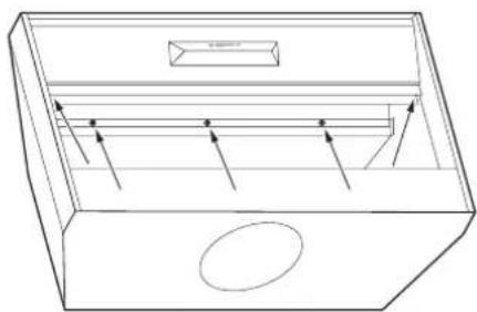
natural_image
Line drawing of a rectangular drawer with internal compartments and arrows indicating flow or movement (no text or symbols)4 Change the plastic jumper position on the PC board to set your desired maximum CFM.
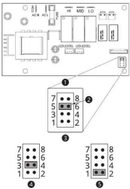
① Jumper Pins
2 Plastic Jumper
3 Jumper 5-6 or 7-8
DEFAULT POSITION
Default Max. Blower CFM
4 Jumper 3-4
Max. Blower CFM
SKSPH3602S: 390
SKSPH4802S: 590
5 Jumper 1-2
Max. Blower CFM
SKSPH3602S: 290
SKSPH4802S: 390
Checking Max CFM Level
1 With the hood off, press and hold the power button for three seconds. The indicator lights will light up to show the maximum CFM level of the hood.
- SKSPH3602S:
- 5 indicator lights: default max. CFM (600)
- 4 indicator lights: max. 390 CFM
- 3 indicator lights: max. 290 CFM
- SKSPH4802S:
- 5 indicator lights: default max. CFM (1200)
- 4 indicator lights: max. 590 CFM
- 3 indicator lights: max. 390 CFM
2 The number of fan speed settings depends on the max CFM setting.
SKSPH3602S: 390 CFM = max. 4 speeds and 290 CFM = max. 3 speeds
SKSPH4802S: 590 CFM = max. 4 speeds and 390 CFM = max. 3 speeds


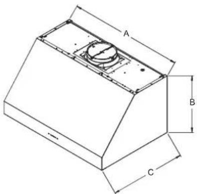
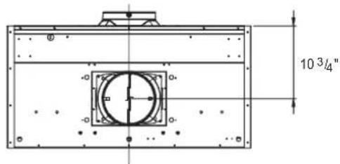
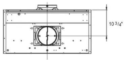
Dimensions
Tolerances: +1/16", -0 (1.6 mm, -0), unless otherwise stated.
NOTE
The exhaust duct(s) and electrical wiring can be connected from either the top or the back of the hood.
Top Dimensions Side Dimensions
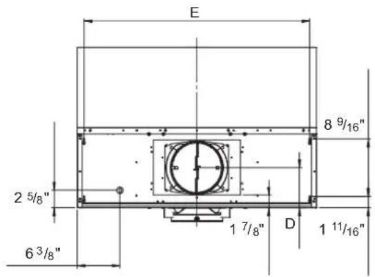
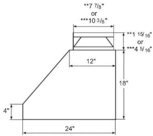
* Single Blower Rect. Ducting Dimension
** Single Blower Round Ducting Dimension
*** Dual Blower Dimension
Back Dimensions
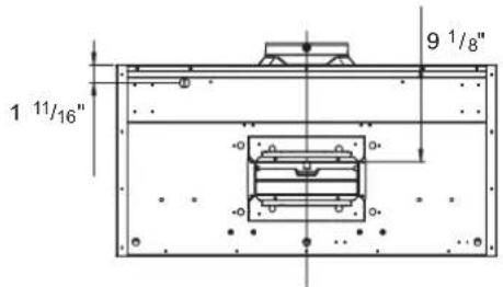

Overall Dimensions
natural_image
Isometric technical drawing of a mechanical component with labeled dimensions A, B, and C (no text or symbols beyond labels)| Model A B C D E | |||||
| SKSPH4802S 48" | 18" 24" 6" | 45^7/8" | |||
| SKSPH3602S 36" 33 | 7/8" | ||||
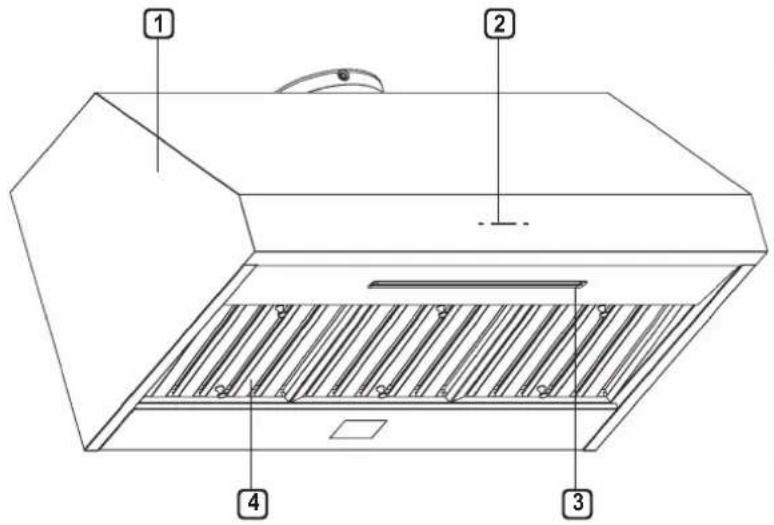
PRODUCT OVERVIEW
Parts

① HOOD
② ICON TOUCH CONTROL PANEL
③ LED STRIP LIGHT
④ BAFFLE FILTER
(SKSPH4802S: 4pcs, SKSPH3602S: 3pcs)
Accessories
Included Accessories
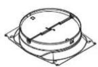
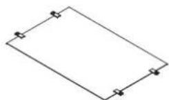
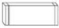
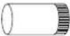
8" round collar Top cover plate 3 1/4"x10"
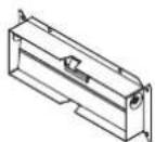
rectangular duct collar
Manual
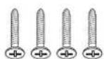
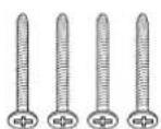
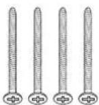
M6 x 1" (4) M6 x 1-1/2" (4) M6 x 2" (4) M3.5 x 8 (4)

3/16 x 3/8 (4) Wire Caps (3) Washers (4)

PLANNING THE INSTALLATION

WARNING
Observe all governing codes and ordinances during planning and installation. Contact your local building department for further information. Use only duct work deemed acceptable by state, municipal and local codes.
Cabinet Layout

WARNING
To reduce the risk of personal injury caused by reaching over a hot appliance, cabinet storage space located directly above the range should be avoided.
Minimum Cabinet Width
| Models Width | |
| SKSPH4802S 48" | (121.9 cm) |
| SKSPH3602S 36" | (91.5 cm) |
Ducting
A minimum of 8" round or 3-1/4" x 10" rectangular duct must be used to maintain maximum air flow efficiency for single blower and 10" round duct for dual blower.
Always use rigid metal ducts only. Flexible ducts could restrict air flow by up to 50%.
Also use calculation (on page 13) to compute total available duct run when using elbows, transitions and caps.
ALWAYS, when possible, reduce the number of transitions and turns. If long duct run is required, increase duct size from 8" to 10".
If turns or transitions are required, install as far away from hood duct output and as far apart as possible.
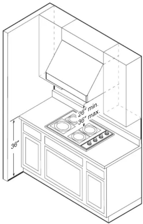
Minimum mount height between range top to hood bottom should be no less than 26".
Maximum mount height should be no higher than 36".
It is important to install the hood at the proper mounting height. Mounting the hood too low could result in heat damage and fire hazard. Mounting the hood too high will make it hard to reach and reduce its performance and efficiency.
If available, also refer to the range manufacturer's height clearance requirements and recommended hood mounting height above range.
Vertical Ducting:
- 8" round minimum (single blower)
- 10" round minimum (dual blower)
Horizontal Ducting:
- 3-1/4" x 10" minimum (single blower)
- 8" round minimum (single blower)
- 10" round minimum (dual blower)

CAUTION
DAMAGE DURING SHIPPING / INSTALLATION:
- Please fully inspect unit for damage before installation.
- If the unit is damaged in shipment, return the unit to the store in which it was bought for repair or replacement.
- If the unit is damaged by the customer, repair or replacement is the responsibility of the customer.
- If the unit is damaged by the installer (if other than the customer), repair or replacement must be made by arrangement between customer and installer.
12 PLANNING THE INSTALLATION
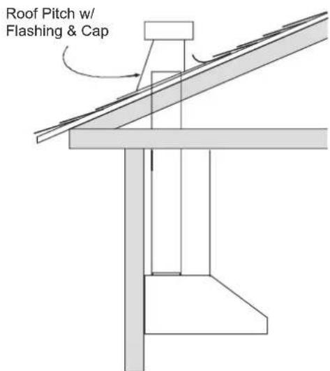
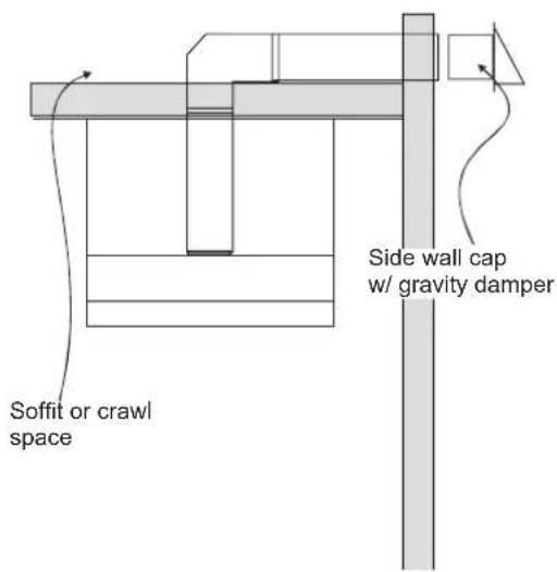
Ducting Options

WARNING
Fire Hazard
- NEVER exhaust air or terminate duct work into spaces between walls, crawl spaces, ceiling, attics or garages.
- All exhaust must be ducted to the outside.
- Use metal ductwork only.
- Fasten all connections with sheet metal screws and tape all joints with certified Silver Tape or Duct Tape.
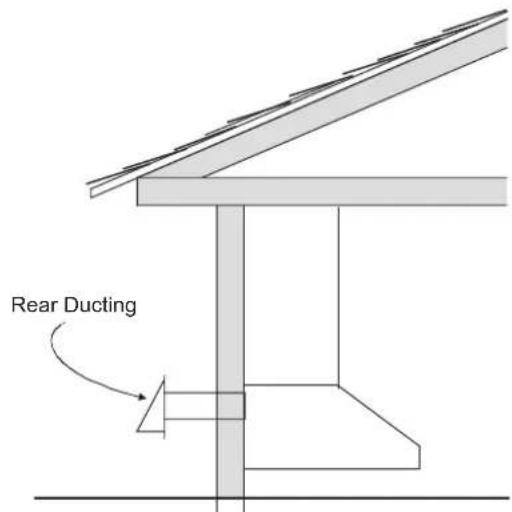
Sample Ducting Options
Ducting Calculation Sheet
| Duct pieces | Equivalent length x number used = | Total | |
 | 3-1/4" x 10" Rect., straight | 1 Ft. x ( ) = Ft. | |
 | 6" Round, straight | 1 Ft. x ( ) = Ft. | |
 | 7"-10" Round, straight | 1 Ft. x ( ) = Ft. | |
 | 3-1/4" x 10" Rect.90° elbow | 15 Ft. x ( ) = Ft. | |
 | 3-1/4" x 10" Rect.45° elbow | 9 Ft. x ( ) = Ft. | |
 | 3-1/4" x 10" Rect.90° flat elbow | 24 Ft. x ( ) = Ft. | |
 | 3-1/4" x 10" Rect. wall cap with damper | 30 Ft. x ( ) = Ft. | |
 | 3-1/4" x 10" Rect.to 6" round transition | 5 Ft. x ( ) = Ft. | |
 | 3-1/4" x 10" Rect.to 6" round transition 90° elbow | 20 Ft. x ( ) = Ft. | |
 | 6" Round, 90° elbow | 15 Ft. x ( ) = Ft. | |
 | 6" Round, 45° elbow | 9 Ft. x ( ) = Ft. | |
| Subtotal column 1 = Ft. | |||
| Duct pieces | Equivalent length x number used = | Total | |
 | 6" Round wall cap with damper | 30 Ft. x ( ) = Ft. | |
 | 6" Round, roof cap | 30 Ft. x ( ) = Ft. | |
 | 6" round to 3-1/4" x 10" rect. transition | 1 Ft. x ( ) = Ft. | |
 | 6" round to 3-1/4" x 10" rect. transition 90° elbow | 16 Ft. x ( ) = Ft. | |
 | 7" - 10" Round, 90° elbow | 15 Ft. x ( ) = Ft. | |
 | 7" - 10" Round, 45° elbow | 9 Ft. x ( ) = Ft. | |
 | 7" - 10" Round wall cap with damper | 30 Ft. x ( ) = Ft. | |
 | 7" - 10" Round, roof cap | 30 Ft. x ( ) = Ft. | |
 | 7" round to 3-1/4" x 10" rect. transition | 8 Ft. x ( ) = Ft. | |
 | 7" round to 3-1/4" x 10" rect. transition 90° elbow | 23 Ft. x ( ) = Ft. | |
| Subtotal column 2 = Ft. | |||
| Subtotal column 1 = Ft. | |||
| Total ductwork = Ft. | |||
Maximum Duct Length: For satisfactory air movement, the total duct length should not exceed 100 equivalent feet.
Ductwork Design Tips
Wherever possible, reduce the number of transitions and turns to as few sharp angles as possible. Two staggered 45^ angles are better than one 90^ .
Keep turns as far away from the hood exhaust as possible, and allow as much space between bends as possible.
For best performance, use round ducts instead of rectangular, especially when elbows are required.
If multiple elbows are used, try to keep a minimum of 24" of straight duct between them.
Avoid "S" or "back to back" use of adjacent elbows.
In regions where the weather gets extremely cold, use thermal breaks, such as a short section of non-metallic duct, to avoid indoor heat loss. Locate the break as close as possible to the outside pass-through point.
Do not use flexible metal duct.
Do not use ductwork that is smaller in cross-sectional area than the recommended types above.
Power Supply

WARNING
- The information in this manual should be followed exactly. Failure to do so could result in fire or electrical shock, causing property damage, personal injury or death.
- All electrical work must be performed by qualified electrician or person with similar technical knowledge and background.
- For personal safety, remove house fuse or open circuit breaker before beginning installation. Do not use extension cord or adapter plug with this appliance.
- Follow national electrical codes or prevailing local codes and ordinances.
Electrical Supply
This appliance requires a 120V 60Hz electrical supply, and must be connected to an individual, properly grounded branch circuit, protected by a 15 or 20 ampere circuit breaker or time delay fuse. Wiring must be 2 wire w/ ground. Please also refer to the Electrical Diagram label on product.
To house circuit breaker panel or fuse box
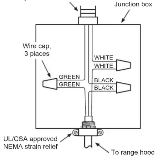
3 Wire Connection to Junction Box
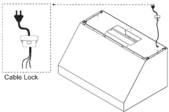
Cable Lock
A cable locking connector (not supplied) might also be required by local codes. Check with local requirements and codes, and purchase and install appropriate connector if necessary.
Verify the Package Contents
Unpack the parts box and verify that all parts and accessories have been included. If any item is missing or damaged, please contact the dealer immediately. Do not install a damaged or incomplete appliance.
Make sure you have everything necessary for proper installation before proceeding.
INSTALLATION INSTRUCTIONS

WARNING
- Do not install the range hood unless the electrical service provided meets the range hood specifications.
- Observe all governing codes and ordinances during installation. Contact your local building department for further information.
- A qualified technician must complete the installation of this built-in appliance. More than one person is required to raise the hood into place. The owner is responsible to make sure the hood is properly installed.
1 Start by removing the baffle filters from the bottom of the hood. Put them in a safe location so that they will not be damaged.
2 If the hood will be installed so that air will exhaust out of the back, the blowers must be rotated into the correct position before hanging the hood.
Rotating the Blower
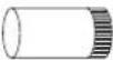
This range hood is equipped standard with a 8" round vertical duct option. To convert from 8" round vertical to 8" round horizontal ducting or 3-1/4" x 10" rectangular horizontal ducting please following the instructions below.
Vertical to Horizontal Ducting Conversion
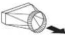
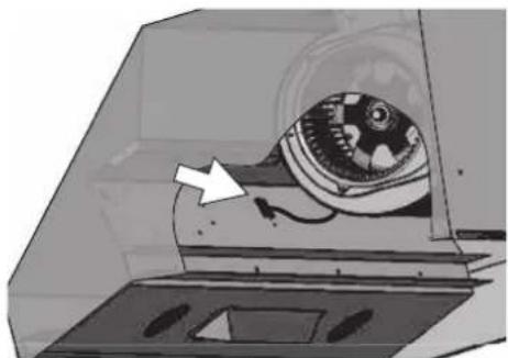
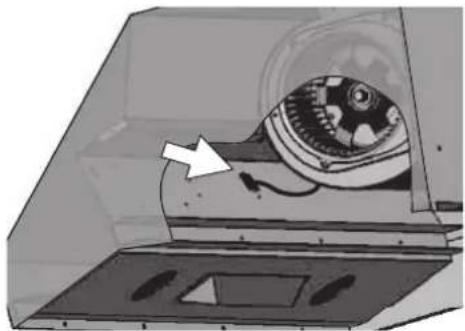
1 Disconnect the blower plug.
natural_image
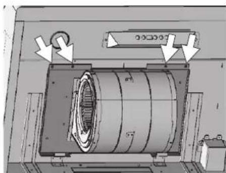
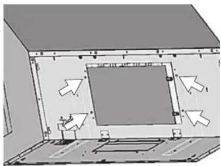
Illustration of a mechanical device with a rotating head and internal components, showing no visible text or symbols.2 Remove the 4 screws on the interior of the hood body which attach the single blower plate to the top of the hood body. Remove the single blower and blower plate.
natural_image
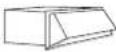
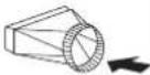
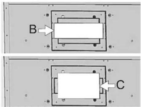
Technical diagram of a mechanical assembly with directional arrows indicating motion or force (no readable text or symbols)3 At the back, knock out plate B for rectangular ducting, or plate C for 8-inch round ducting.
16 INSTALLATION INSTRUCTIONS
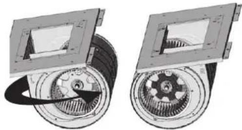
4 Remove the 4 screws holding the blower to the blower plate. Turn the blower 180 degrees and reattach it to the blower plate.
natural_image
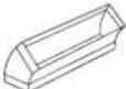
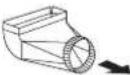
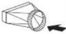
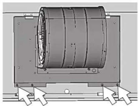
Mechanical assembly diagram showing two views of a gear and rotor components (no text or labels)5 Position the single blower and blower plate as shown, tucking the back of the blower plate into the tabs at the back of the hood. Secure the blower plate using the 4 screws removed in step 2.
natural_image
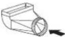
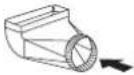
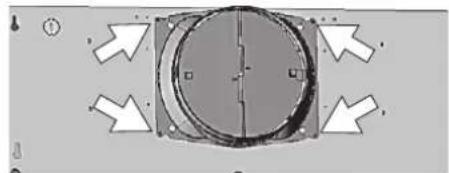
Mechanical assembly diagram showing a cylindrical component mounted on a frame with directional arrows indicating motion (no text or symbols)6 Attach an 8" round duct collar or 3 1/4" x 10" rectangular duct collar to the back of the hood body using four M3.5 x 8 screws.
natural_image
Pure mechanical component diagram with arrows indicating direction, no text or symbols present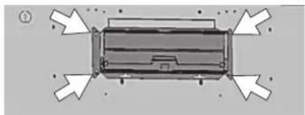
natural_image
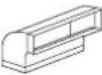
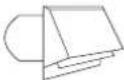
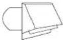
Top-down schematic of a vehicle or container with directional arrows indicating flow or movement (no text or symbols)7 From inside the hood body, align the top cover plate to the top of the hood body. Attach the top cover plate from the outside of the hood, using four 3/16" x 3/8" screws.
natural_image
3D diagram of a room interior with directional arrows indicating movement or flow (no text or symbols)8 Connect the blower plug.
natural_image
Diagram of a mechanical device inside a transparent enclosure, showing internal components and a white arrow indicating direction (no text or symbols present)Mounting the Range Hood

CAUTION
- At least two installers are required due to the weight and size of the hood.
1 Select the preferred ducting application (vertical or horizontal) and prepare the hood. Refer to page 15 for single blower horizontal ducting.
2 Plumb and mark center line.
3 Choose the desired height above the cooking surface (26" minimum). Level and mark the hood bottom (line A in Fig. 1).
4 Level and mark the top of the wood board (line B in Fig. 1), 16 7/8" from line A.
5 Draw a center line on the wood board as shown. Align the center of the board with the center line on the wall and align the top of the board with line B. Attach the board to the wall studs using four M6 wood screws.
Wood Board Dimensions : (W x D x H)
SKSPH3602S - 33" x 1/2" x 4"
SKSPH4802S - 45" x 1/2" x 4"
6 Prepare the duct pipe and duct cutouts in the upper cabinet if needed, or in the wall if ducting the hood horizontally. Refer to the hood specifications on page 9 for duct cutout dimensions.
7 Prepare the electrical wiring and electrical cutouts in the upper cabinet if needed, or in the wall if horizontal electrical hook up is required. Refer to the hood specifications on page 9 for electrical cutout dimensions.
8 Mount the hood onto the wood board and secure it using four M6 wood screws.
9 Insert two M6 wood screws into the wall through the screw holes in the lower body. See Fig. 2 for dimensions between screw holes.
10 Install the electrical connection.
11 Install the ductwork and seal it with certified aluminum duct tape.
12 Power up the hood and check for leaks around the duct tape.
13 Install the baffle filters.
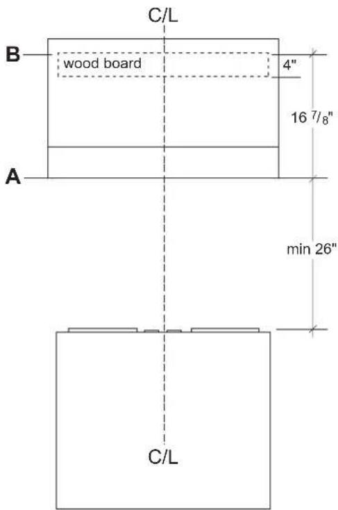
FIG. 1
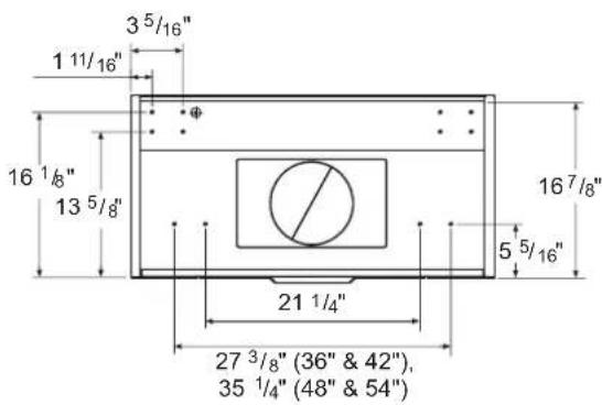
FIG. 2

WARNING
- Electrical wiring must be done by qualified personnel in accordance with all applicable codes and standards.
- This range hood must be properly grounded. Turn off electrical power at main power supply before wiring.
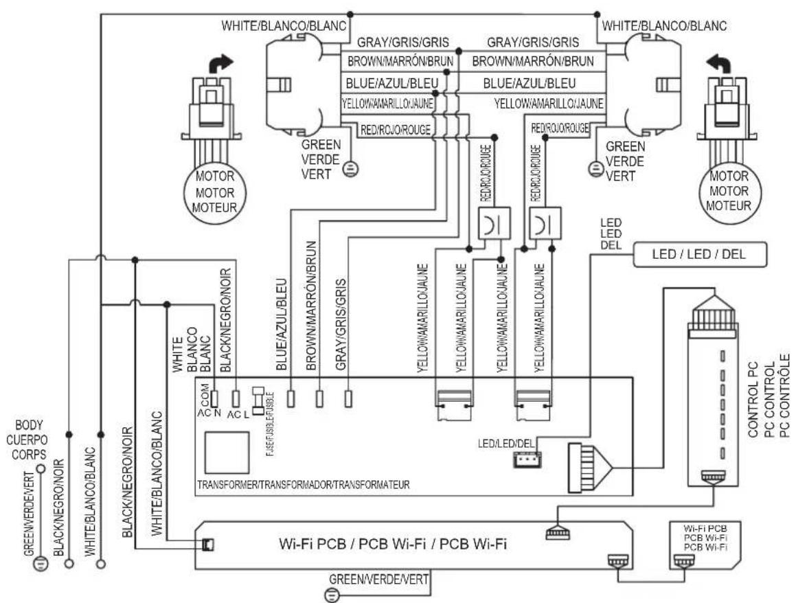
WIRING DIAGRAM
| Models Volts HZ MAX Amps | |||
| SKSPH4802SSKSPH3602S | 120 60 | Single Motor 4 | |
| Dual Motor 7 | |||
flowchart
graph TD
    A["WHITE/BLANCO/BLANC"] --> B["GRAY/GRIS/GRIS"]
    A --> C["BROWN/MARRÓN/BRUN"]
    A --> D["BLUE/AZUL/BLEU"]
    A --> E["YELLOW/MARILLO/JAUNE"]
    A --> F["RED/ROJ/ROUGE"]
    A --> G["GREEN VERDE VERT"]
    A --> H["WHITE/BLANCO/BLANC"]
    A --> I["MOTOR MOTOR MOTEUR"]
    A --> J["GREEN VERDE VERT"]
    A --> K["MOTOR MOTOR MOTEUR"]
    A --> L["WHITE/BLANCO/BLANC"]
    A --> M["BACK/NEGRO/NOIR"]
    A --> N["WHITE/BLANCO/BLANC"]
    A --> O["BLACK/NEGRO/NOIR"]
    A --> P["COM AC N AC L"]
    A --> Q["TRANSFORMER/TRANSFORMADOR/TRANSFORMATEUR"]
    A --> R["Wi-Fi PCB / PCB Wi-Fi / PCB Wi-Fi"]
    A --> S["GREEN/VERDE/VERT"]
    A --> T["LED/LED/DEL"]
    A --> U["LED LED DEL"]
    A --> V["LED / LED / DEL"]
    A --> W["CONTROL PC PC CONTROL PC CONTROLE"]
    A --> X["POWER/LED/DEL"]
    A --> Y["POWER/LED/DEL"]
    style A fill:#f9f,stroke:#333
    style B fill:#ccf,stroke:#333
    style C fill:#ccf,stroke:#333
    style D fill:#ccf,stroke:#333
    style E fill:#ccf,stroke:#333
    style F fill:#ccf,stroke:#333
    style G fill:#ccf,stroke:#333
    style H fill:#ccf,stroke:#333
    style I fill:#ccf,stroke:#333
    style J fill:#ccf,stroke:#333
    style K fill:#ccf,stroke:#333
    style L fill:#ccf,stroke:#333
    style M fill:#ccf,stroke:#333
    style N fill:#ccf,stroke:#333
    style O fill:#ccf,stroke:#333
    style P fill:#ccf,stroke:#333
    style Q fill:#ccf,stroke:#333
    style R fill:#ccf,stroke:#333
    style S fill:#ccf,stroke:#333
    style T fill:#ccf,stroke:#333
    style U fill:#ccf,stroke:#333
    style V fill:#ccf,stroke:#333
    style W fill:#ccf,stroke:#333
REMARKS:CONDENSER 11+11μF 250 VAC * 2 FIT AC 120 V 60 Hz
OBSERVACIONES: CONDENSADOR 11+11μF 250 VCA * 2 AJUSTE CA 120 V 60 Hz
NOTES: CONDENSATEUR 11+11μF 250 VAC * 2 FIT AC 120 V 60 Hz
natural_image
Line drawing of a rectangular drawer with internal compartments and arrows indicating flow or movement (no text or symbols)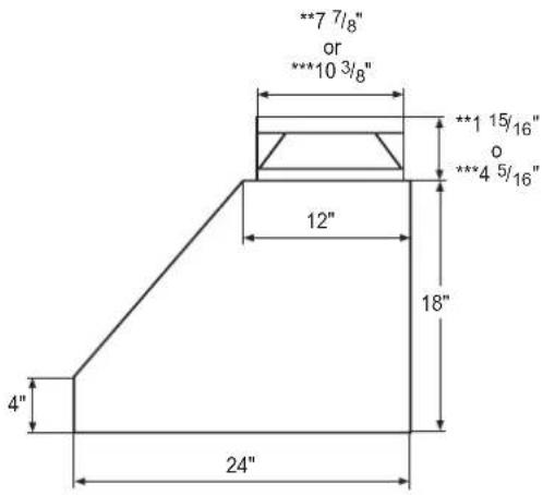
natural_image
Isometric technical drawing of a mechanical component with labeled dimensions A, B, and C (no text or symbols beyond labels)| Modelo A B C D E | |||||
| SKSPH4802S 48" | 18" 24" | 6" | 45^7/8" | ||
| SKSPH3602S 36" | 33 | 7/8" | |||
natural_image
Illustration of a mechanical device inside a transparent enclosure, showing internal components and a white arrow pointing to a component (no text or symbols present)natural_image
Technical diagram of a mechanical assembly with no visible text or symbolsnatural_image
Mechanical assembly diagram showing two views of a gear and rotor components (no text or symbols)natural_image
Mechanical assembly diagram showing a cylindrical component mounted on a frame with directional arrows indicating motion (no text or symbols present)natural_image
Top-down view of a mechanical component with circular features and directional arrows (no text or symbols)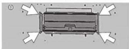
natural_image
Top-down diagram of a vehicle or container with directional arrows indicating flow or movement (no text or symbols)natural_image
Diagram of a 3D room interior with directional arrows indicating movement or flow, no text or symbols present.natural_image
Diagram of a mechanical device inside a transparent enclosure, showing internal components and a directional arrow (no text or symbols)FIG. 2

ADVERTENCIA
10 APERÇU DU PRODUIT
10 Pièces
10 Accessoires
11 PLANIFICATION DE L'INSTALLATION
CARACTÉRISTIQUES DU PRODUIT
natural_image
Line drawing of a rectangular box with internal compartments and a central hole, no text or symbols present8
CARACTÉRISTIQUES DU PRODUIT
CFM = max. 3 vitesses
SKSPH4802S: 590 CFM = max. 4 vitesses et 390
CFM = max. 3 vitesses


Dimensions

natural_image
Isometric technical drawing of a mechanical component with labeled dimensions A, B, and C (no text or symbols beyond labels)| Modèle A B C D E | |||||
| SKSPH4802S 48" | 18" 24" | 6" | 45^7/8" | ||
| SKSPH3602S 36" 33 | ^7/8" | ||||
APERÇU DU PRODUIT
Pièces
natural_image
Illustration of a mechanical device inside a transparent enclosure, showing internal components and a white arrow pointing to a component (no text or symbols present)natural_image
Technical diagram of a mechanical assembly with directional arrows indicating motion or force (no readable text or symbols)natural_image
Mechanical assembly diagram showing two views of a gear and rotor components (no text or symbols)natural_image
Mechanical assembly diagram showing a cylindrical component mounted on a frame with directional arrows indicating motion (no text or symbols present)natural_image
Pure mechanical component diagram with arrows indicating direction, no text or symbols present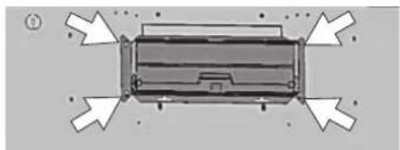
natural_image
Top-down view of a rectangular electronic device with directional arrows indicating orientation (no text or symbols)natural_image
Diagram of a room interior with directional arrows indicating movement or flow (no text or symbols present)natural_image
Illustration of a mechanical device inside a transparent enclosure, with an arrow pointing to a component (no text or symbols present)FIG. 2

AVERTISSEMENT
Customer Information Center
1-855-790-6655 USA
1-888-289-2802 CANADA
Register your product Online!
www.signaturekitchensuite.com