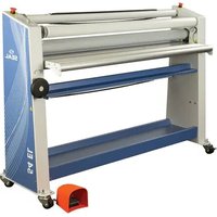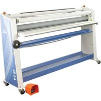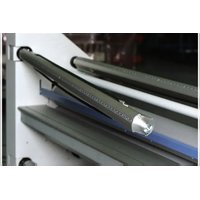
62 Pro S - Laminating machine SEAL - Free user manual and instructions
Find the device manual for free 62 Pro S SEAL in PDF.


User questions about 62 Pro S SEAL
0 question about this device. Answer the ones you know or ask your own.
Ask a new question about this device
Download the instructions for your Laminating machine in PDF format for free! Find your manual 62 Pro S - SEAL and take your electronic device back in hand. On this page are published all the documents necessary for the use of your device. 62 Pro S by SEAL.
USER MANUAL 62 Pro S SEAL
Mounter and Laminator
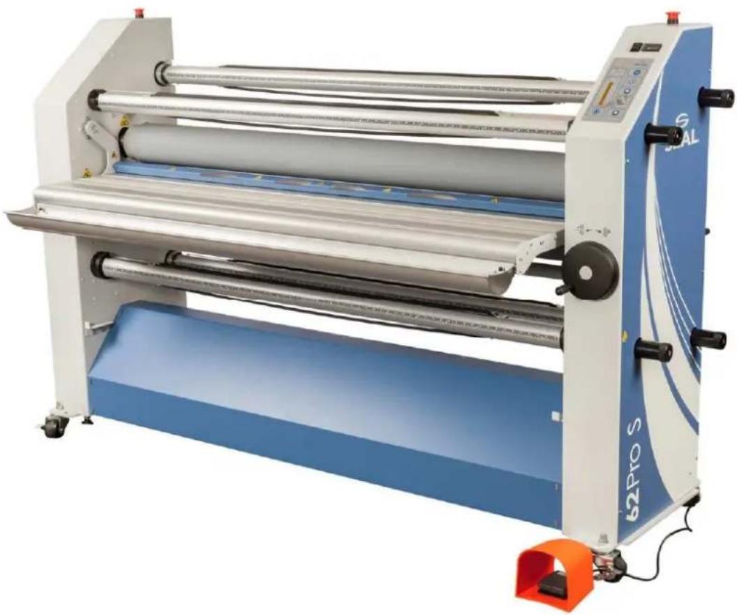
User Manual
Manuel d'utilisation
Betriebsanleitung
Manual de uso
Manuale d'uso
SEAL
977-0079_D October, 2017
English
All rights reserved
All information included in this manual as well as information included in supplements or addendum to this manual is subject to copyright law. This information shall not be used, copied, reproduced, transmitted or disclosed to third parties without our prior written consent.
Seal® assumes no responsibility for any errors that may appear in this document nor does it make expressed or implied warranty of any kind with regard to this material, including, but not limited to, the implied warranties of merchantability and fitness for a particular purpose.
Seal® shall not be liable for incidental or consequential damages in connection with, or arising out of the furnishing, performance, or use of this document and the program material which it describes.
Français
Thank you for purchasing your SEAL 62 Pro S.
Maximum effort has been invested in the design of this machine to give you years of reliable service.
As you become familiar with your machine you will appreciate the high quality of its output and the excellence in engineering stated in its smartly styled design.
The machine described in this manual is a multi-functional machine that can perform the following processes;
high-quality lamination,
- panel mounting of images,
- mounting and laminating in one pass,
- decaling.
A vast number of laminating products are available. All of them with their own applications and processing specifications.
This manual gives a general description of various processes.
For more details on film choice and application solutions refer to the Seal films and adhesives product catalog.
On this machine the process results can be controlled by:
speed setting,
- pressure setting,
- unwind tension of the film(s),
temperature setting.
THIS MANUAL
This manual is intended for the user of the 62 Pro S. Read this manual carefully before starting the machine.
This manual contains important information for correct installation, operation and maintenance of the machine.
It also contains important instructions to prevent accidents, personal injury and/or serious damage prior to or during operation of the machine.
Familiarize yourself thoroughly with the functioning and operation of this machine and strictly observe the directions given.
If you have any questions or need further details on specific aspects related to this machine, please do not hesitate to contact us. The address and phone number are stated on the copyright page.
Chapter 1 will provide you with a summary of the manufacturers warranty information. It also describes the safety features installed on the machine and gives a number of safety instruction and warnings. Read this chapter carefully.
Chapter 2 provides a general description of the machine and of the process principles to help first time users to find their way on this machine.
Chapter 3 specifies the machine, machine dimensions and the dimensions of the materials to be used on this machine.
Chapter 4 guides you through the installation of the machine. This chapter also provides information for moving, transport and decommissioning of the machine.
Chapter 5 guides you through the operation in various processes to develop basic knowledge of the machine.
Chapter 6 provides maintenance procedures for long time efficient and trouble free operation of the machine. The trouble shooting section gives a number of suggestions in case the results are not up to your expectations.
Chapter 7 is the glossary and explains a number of terms used in this manual.
TABLE OF CONTENTS
1. Warranty and Safety instructions 1
1.1 Warranty 1
1.1.1 Warranty conditions 1
1.1.2 Warranty period 1
1.2 End of Life (EOL) Statement 1
1.3 Safety 2
1.3.1 Safety features 2
1.3.2 Safety instructions 3
1.4Warnings 3
1.4.1 General ESD-warning 3
1.4.2 In this manual 3
1.4.3 On the machine 4
2 Description 5
2.1 General description 5
2.2 Parts identification 6
2.3 Process principle 7
3 Specifications 8
3.1 Identification 8
3.2 Machine dimensions 8
3.3 Material specifications 9
3.4 Machine specifications 9
4 Installation 10
4.1 Unpacking 10
4.2 Installation 11
4.3 Transport 12
5 Operating 13
5.1 Process controls 13
5.1.1 Control panel 13
5.1.2 Heater control 15
5.1.3 Additional controls 16
5.1.4 Error indications 18
5.2 Operating modes 19
5.2.1 Normal mode 19
5.2.2 Slow mode 19
5.3 Placing film rolls 20
5.3.1 Auto-grip shafts 20
5.3.2 Use of films with release liner 20
5.3.3 Loading shaft with film rolls 21
5.3.4 Use of a splitter bar 22
5.3.5 Presetting the tension 22
5.3.6 Pressure setting 22
5.4 Webbing 23
5.4.1 Upper section only 24
5.4.2 Upper and lower section 24
5.4.3 Result to Roll or Roll to roll 26
5.5 Processes and settings 27
5.5.1 Mounting images or decals 27
5.5.2 Pre-coating panels 28
5.5.3 Over-lamination 28
5.5.4 Single-sided lamination 28
5.5.5 Double-sided lamination 29
5.5.6 Decaling 29
5.6 Unloading 29
6 Maintenance 30
6.1 Cleaning 30
6.1.1 Cleaning the silicone covered rollers. 30
6.2 Preventive maintenance 30
6.2.1 Auto-grip shafts 31
6.3 Trouble shooting 31
6.4 Technical assistance 33
7 Glossary 34
1. WARRANTY AND SAFETY INSTRUCTIONS
1.1 Warranty
The warranty period and conditions stated in this chapter are merely a summary of the general Seal warranty conditions. For the exact details on the warranty period and conditions for your machine, please contact your dealer.
1.1.1 Warranty conditions
The manufacturer warrants to the original end user* that the machine when proven defective in materials or workmanship, within the applicable warranty period will be repaired, or (at our option) replaced without charge.
Note: The main rollers are subject to normal wear and tear and therefore have warranty on material defects only.
The manufacturer or its representative shall not be liable for any damage caused by the machine nor loss of productivity.
Warranty is voided when:
- Changes or modifications are made to this machine, not explicitly approved by the manufacturer.
- The machine is changed or modified by unauthorized persons.
- The machine is used under other than normal working conditions.
- The machine is used for purposes other than intended for (see page 3).
- The original end user is the person that first purchased the machine from the manufacturer or its representative.
1.1.2 Warranty period
The standard warranty period on this machine is one year from the date of purchase.
This period however can be longer due to local law or purchase agreement.
The main rollers have a warranty period of 6 months on material defects only.
The warranty ends when:
The periods stated above have expired.
- The machine changes possession.
- Warranty is voided by any of the conditions mentioned above.
1.2 End of Life (EOL) Statement
Your SEAL® 62 Pro S has been designed to provide years of reliable and trouble free service, but at some point in time it may be necessary to retire this unit from service. To protect our Environment specific guidelines and requirements should be followed.
This machine is primarily constructed from steel sheet metal and contains no hazardous materials. This system has electrical components that must be removed from the machine and disposed of according to country, regional or local requirements.
The SEAL® 62 Pro S is Industrial Equipment as stated in Category 6 of Annex 1A of the EU (Waste of Electrical and Electronic Equipment) WEEE Directive 2012/19/EU. This Directive as of 2014 applies to this equipment type, and in the future this Directive should be reviewed for any changes that may now apply.
1.3 Safety
This machine is provided with safety equipment to promote safe machine operation.
The manufacturer has done everything possible to prevent any possible danger and to inform you as accurately and comprehensively as possible of any hazards relating to the operation of the machine.
You should nevertheless proceed with caution when operating the machine.
Read the safety instructions below and familiarize yourself with the warning symbols summarized in theWarnings section.
1.3.1 Safety features
Emergency stops
The machine has 2 emergency stops. When activated the machine will come to a complete stop and the power to the motor controller is switched off. The emergency stops must be disengaged before a restart is possible.
Optical safety devices
The machine has an optical safety device at both sides of the nip at the main rollers. These devices perform a check of the operation between transmitter and receiver.
When an error is detected (e.g. the signal is interrupted) the motor will stop and the motor controller will be disabled.
The stop signal from the optical device on the output side (rear when running forward or front when running reverse) of the nip is overruled.
The stop signal from the optical device on the input side is overruled when the slow mode is selected and the footswitch is pressed.
Safety footswitch
The safety footswitch is used as remote control to start and stop the machine in the normal and the slow mode.

WARNING:
THE OPTICAL SAFETY DEVICE IS DISENGAGED WHEN USING THE SAFETY FOOTSWITCH IN SLOW MODE.
SO, KEEP CLEAR OF THE NIP WHEN PRESSING THE FOOTSWITCH, WHILE SLOW MODE IS ACTIVE.
The safety footswitch is protected with a safety lock to prevent accidental switching. Insert the forefoot completely to disengage this lock.
Slow mode
The slow mode is used when setting up the machine with new films or images.
When in slow mode the machine is started with the footswitch it will run at low speed so that the operator has both hands free to position and feed new film or image correctly into the machine.
1.3.2 Safety instructions
Work safely!
The owner of the machine is responsible for safe operation of the machine. He therefore is obliged to familiarize operating personnel with the contents of this manual and make them aware of all possible hazards.
Do not change, remove or disable the safety facilities.
1.4Warnings
1.4.1 General ESD-warning

WARNING:
DANGER OF ELECTRIC SHOCK BY ELECTROSTATIC DISCHARGE. PROCESSING FILMS THROUGH LAMINATING ROLLERS WILL CAUSE BUILD-UP OF ELECTROSTATIC CHARGES.
An anti-static floor coating and wearing anti-static clothing and footwear can reduce the risk of ESDshock.
1.4.2 In this manual
In this manual you will find 3 levels of warnings.

WARNING:
THE WARNINGMESSAGE IS USED WHEN A LIFE-THREATENING SITUATION MAYARISE OR PERSONAL INJURY CAN OCCUR. FOLLOW THE INSTRUCTIONS Closely.

CAUTION:
The caution message is used when there is danger of damage to the machine or materials.
Follow the instructions to prevent this damage.
Note:
This message is used to give you useful information for easier operation, to prevent waste of material, etc..
1.4.3 On the machine
On the machine (See Figure 1) you will find the following warning symbols in black on a yellow background.
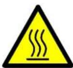
HOT OBJECTS (1)
DANGER OF GETTING BURN WOUNDS.
This symbol is placed on the inside side panel on both sides of the machine, just above the upper main roller, visible from the front and rear side. And on the image guide at the input side of the nip and on the output nip safety bar (1).

ROTATING PARTS (2)
DANGER OF GETTING INJURED BY ROTATING PARTS.
MAKE SURE THAT THESE ROTATING PARTS DO NOT CATCH YOUR FINGERS, CLOTHING, HAIR, ETC.
This symbol is placed on in-feed table arms and on the cabinets just above the output table (2).
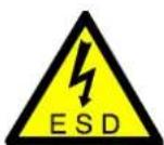
ESD SHOCK (3)
DANGER OF GETTING AN ELECTRIC SHOCK CAUSED BY ELECTROSTATIC CHARGE BUILD-UP IN THIS AREA.
This symbol is placed on those places where electrostatic charges can be build-up. The machine parts close to the nip and the output material are most likely building up charges. Therefore ESD-symbols are placed on the image guide and the output nip safety bars (3)
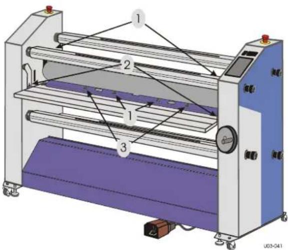
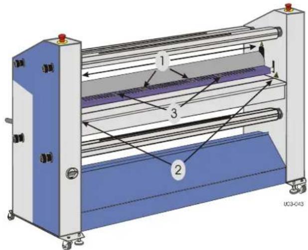
Figure 1: Warning symbol locations.
2 DESCRIPTION
This chapter describes the machine and its operating basics.
2.1 General description
The machine described in this manual is a mono-directional machine dedicated for processing pressure sensitive or heat activated materials.
While feeding through images and the coating films, the two silicone coated main rollers generate the pressure.
The area where the upper and lower main roller meet is called the "nip". The upper main roller can be moved up or down manually, so the nip can be varied to feed materials of various thicknesses. A mechanical read-out shows the value set.
The nip setting hand wheel also sets the pressure for the laminating process.
The lower main roller is motor driven. The speed can be manually set between zero and a given maximum value.
When the top roller is equipped with a heater, heat activated materials can also be processed with these rollers. The heater has a separate control unit, to set and control the temperature (see section 5.1.2).
Four material shaft positions are standard on the machine. The two shaft positions at the bottom can function as both an unwind or as a wind-up position, which makes the machine more flexible and enables roll to roll processing for some processes.
The machine can be divided into an upper and a lower section.
The upper section, above the in-feed table, consists of 2 auto-grip shaft positions and a splitter bar (idler). The rear shaft position is for unwinding film, the one on the front side for winding e.g. the release liner.
The 2 shaft positions in the lower section are both unwind/wind-up positions, which gives maximum flexibility for this section. So it can be used for supplying the bottom laminate from rear to front, but also for supplying the images from front to rear (roll to roll).
For this Roll to Roll processing an optional Media unwind is available to support the image supply roll.
When the optional Easy Feed in-feed table is installed, the media trough can be used as media unwind.
2.2 Parts identification
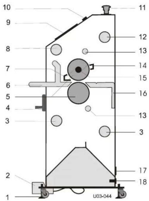
1 Castors and leveling feet
2 Foot switch
3 Unwind/wind-up shaft with tension control
4 Nip setting and pressure control wheel
5 Main rollers
6 In-feed table
7 Image guide
8 Wind-up shaft with tension control
9 Control panel
10 Heater control
11 Emergency button
12 Unwind shaft with tension control
13 Splitter bars
14 Output nip safety bar
15 Heater
16 Output table
17 Identification label
18 Main power entry
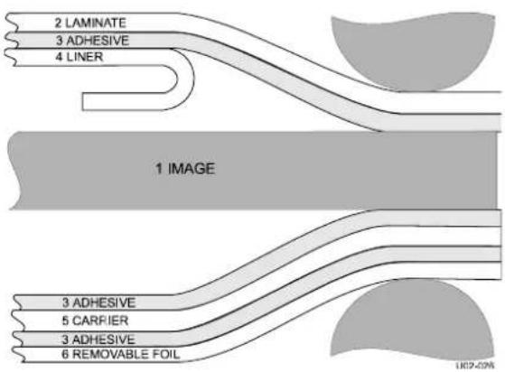
Figure 2: Main parts identification.
Figure 3 shows the cross section of the layers in the decal process. In this process the largest number of layers is possible.
Figure 3: Cross section of layers, when making a decal.
Decaling in general is a cold process, where the bottom layer has no release liner. The release liner (6 removable foil) is not removed during the decal process. The carrier (5) is not always present. In this case the release liner (6) also functions as carrier. The top layer is a normal pressure sensitive laminate, in this case with a release liner. Heat sensitive laminates in general have no release liners (4), so they just consist of the laminate (2) with a heat activated adhesive layer (3).
2.3 Process principle
In all processes the materials are fed through the nip from the front side to be joined together by pressure and/or temperature.
A process that makes maximum use of the machine is shown in Figure 4. Shown is an image roll to roll decaling process with a pressure sensitive top and bottom layer.
The top film has a release liner and the bottom layer is without release liner.
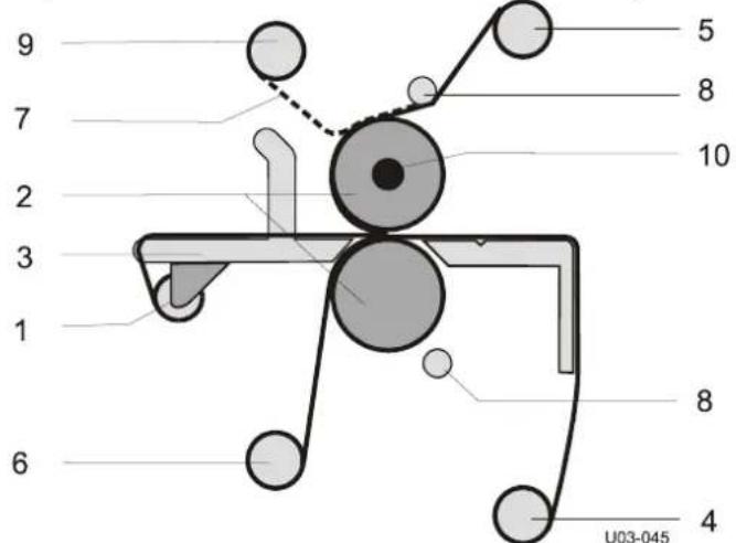
Figure 4: Creating Pop-up art, including image supply from roll.
The image that has to be coated on both sides is unwound from a roll on the optional table mounted media unwind (1) and fed between the main rollers (2) via the in-feed table (3). The bottom unwind/wind-up shaft (4) is set as a wind-up to roll up the finished product.
When the optional Easy Feed in-feed table is installed, the media trough can be used to place the image roll.
The top coating film is taken from a supply roll on the (rear) upper unwind shaft (5). The bottom coating film is taken from a supply roll on the (front) lower unwind/wind-up shaft (6).
When using a pressure sensitive laminate, it often has a release liner (7) that has to be removed. As in the top half, it runs via a splitter bar (8) where the release liner is removed. This release liner is rolled up onto a cardboard core placed on the wind-up shaft (9) in the upper section.
A mounting film has adhesive on both sides and release liner on just one side, and this has to stay on until the image is mounted. So a mounting film is processed the same way as a laminate without release liner.
Note:
When using a pressure sensitive laminate without a release liner (like in the bottom section), it must not run via the splitter bar to avoid adhesive residue getting on this bar.
Because the rear position is needed for the result, the bottom film is taken from the front position. The unwind/wind-up combi functions in the bottom positions make this exchange of unwind and wind-up possible.
The upper main roller can be heated (10). Heat sensitive film is fed under the splitter bar (8) providing maximum contact surface with the heated main roller.
3 SPECIFICATIONS
3.1 Identification
The machine identification label (example in
Figure 5) is located at the bottom of the right-hand cabinet, on the rear side of the machine. This label indicates the model (version) and the rated power of the machine.
CAUTION: The power supply must be able to provide the rated power according to the electrical code requirements for the area of installation. Consult your local electrician for the power supply requirements.
Figure 5: Machine identification labels (example).
3.2 Machine dimensions
Uncrated: Metric American
Width 223.2 cm 87.9 in.
Height 140.7 cm 55.4 in.
Depth (excl. table) 65.4 cm 25.7 in.
Depth (incl. in-feed table) 66.6 cm 26.2 in.
Depth (incl.Easy feed table and trough) 92 cm 36.2 in.
Working height 89 cm 35.0 in.
Weight 488 kg 1076 lbs
Crated:
Width 228 cm 89.8 in.
Height 167.5 cm 64.8 in.
Depth 90 cm 35.4 in.
Weight 540 kg 1090 lbs
Working area:
Width 420 cm 168 in.
Depth 190 cm (75 in.) + 2x maximum board length
Note: A relative humidity between 50% to 70% helps reducing ESD-build-up. Anti-static clothing and footwear of the operator and an anti-static floor coating also helps reduce the build-up of electrostatic charges (ESD).
3.3 Material specifications
Maximum width: Metric American
Process up to 50^ (122°F) 1575 mm 62 in.
Process up to 125^ (257°F) 1524 mm 60 in.
Maximum roll diameter:
Material unwind 305 mm 1 ft.
Release liner wind-up (upper wind-up) 180 mm 6 in.
Release liner wind-up (lower wind-up) 200 mm 8 in.
Maximum panel thickness: 38 mm 1.5 in.
Roll core inside diameter: 76.2 mm 3 in.
3.4 Machine specifications
Power supply requirements:
62 Pro S 1N/PE 230VAC +/- 10% , 50/60Hz, 16A
62 Pro S (US/CAN) 2W+G 230VAC +/- 10%, 50/60Hz, 16A
For the correct supply voltage version refer to the identification label on the machine.
Standard number of shaft positions:
Material unwind 1 (auto-grip)
Release liner wind-up 1 (auto-grip)
Unwind/wind-up 2 (auto-grip)
Optional features:
Extra plot unwind for 2" and 3" cores (customer installable)
Easy Feed in-feed table (factory installed)
Nip setting: 0-40 mm 0 - 1^9 / 16 in.
Pressure: 1-2.5 N/mm 5.71-14.28 lbf/in.
Process speed:
Maximum 6 m/min 20 ft/min
Slow mode 0.6 m/min 2 ft/min
Maximum roller temperature: 140 °C 284 °F
Noise level <70 dB(A)
4 INSTALLATION

WARNING: INSTALLATION MUST BE CARRIED OUT BY SKILLED PERSONNEL.
Note: Make sure that the machine, in its final location, has adequate space. You will need room to feed, receive and trim images.
4.1 Unpacking
At delivery, the machine is packed in a plastic bag to avoid moisture penetration. It is transported in a carton box and is fastened onto a wooden pallet.
Note: Unpacking the machine requires at least 2 persons.
The machine is equipped with castors that allow easy movement.
Place the pallet in a space where there is enough room to roll the machine off from the pallet (approx. 3x the length).
To unpack, follow the steps below (refer to Figure 7);
- Cut the straps and lift off the carton box.
- Remove the plastic bag.
- Place the two ramps (4) against the roll-off side of the pallet so that the castors (5) will run clear from the edge.
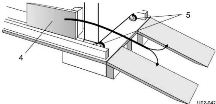
Figure 6: Ramp positioning.
-
Put all the loose accessories aside.
-
Remove the four securing bolts (1).
- Turn down the four leveling feet (2) to lift the machine.
- Remove the wooden blocks (3).
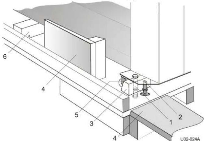
Figure 7: Removing transport parts.
- Remove the screws from the support block (6) and turn the block to remove it from underneath the machine.
- Turn up the four leveling feet (2) completely to put the machine on its castors (5).
- Roll the machine off carefully from the pallet using the ramps.

WARNING:
ROLL THE MACHINE OFF WITH 2 PERSONS. IT IS HEAVY AND CAN NOT BE CONTROLLED ALONE.
Note: Save all packing material for later moving over long distances or discard of according to local regulations.
4.2 Installation
- Move the machine (and the accessories) to its final location.
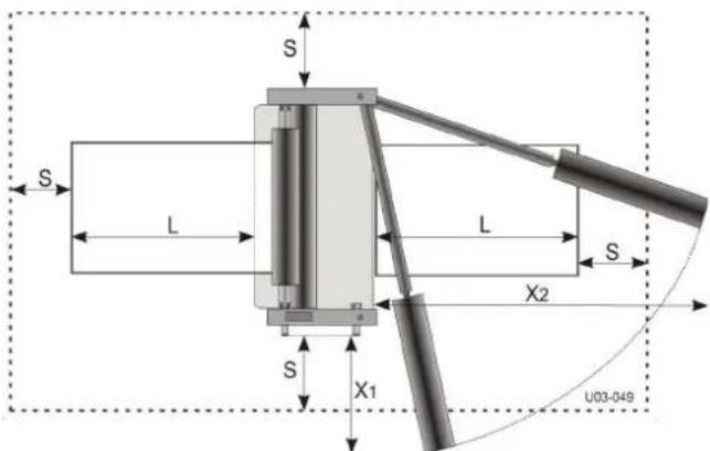
Note: Allow ample working space. See
Figure 8.
L = Maximum board length,
S = Minimum space 60 cm.(24")
X_1 = 130cm(51^ )
X_2 = 330cm (130")
- Turn down the four leveling feet until the castors are off the floor.
-
Remove all transport material.
-
Cut the straps around the shaft supports and remove the foam pads,
- Cut the straps holding the in-feed table arms,
- Cut the straps around the main roller axis and move up the top main roller to remove the transport blocks from the nip,
-
Cut the straps holding the upper pull roller and open the pull rollers to remove the transport plates.
-
Put a spirit level (horizontal) on the upper main roller and (vertical) against the front of both cabinets to level the machine by adjusting the four leveling feet.

Figure 8: Working space.
CAUTION:
Check the mains values before connecting. See section 3.4 for power supply details
- Connect the machine to the mains using the power cable supplied with the machine.

CAUTION:
Only if absolutely necessary, use an extension cable of ample capacity. Unroll the extension cable completely.

WARNING:
MAKE SURE THE POWER SUPPLY CABLE AND/OR THE EXTENSION CABLE IS NOT BLOCKING YOUR WAY AROUND THE MACHINE.
4.3 Transport
The machine can be transported on a smooth surface on its castors.

CAUTION:
Turn the leveling feet up completely to prevent them from bending or breaking if accidentally bumping into an obstacle.
On rough surfaces use a pallet truck or forklift.
When moving the machine over long distances, use the original pallet and packing material and follow the unpacking procedure in the opposite way.
5 OPERATING
This chapter describes the function of the controls and indicators, the operating modes, how to set up and operate the machine and a number of applications.
The sections in this chapter are placed in a sequence in which the information is needed for laminating processes.
For the mounting process the sections 5.3 and 5.4 can be skipped with the exception of setting the pressure (see section 5.3.6).
5.1 Process controls
This section gives an overview of the functions of the controls on the control panel (Figure 9), the heater control (Figure 10) and elsewhere on the machine (Figure 11).
Note:
Switch on the heaters approximately 1 hour before use, if a process requires the rollers to be heated. Close the nip and let the machine run at low speed, to avoid uneven hot spots.
5.1.1 Control panel
This paragraph describes the controls and indicators on the control panel.
When LED's are blinking, this indicates an error. Refer to 5.1.4 for their meaning.
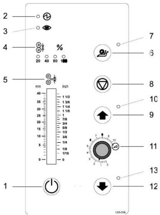
Figure 9: Control panel

Control ON/OFF (1), toggle pushbutton;
Press 1 second to switch the machine from stand by to active and back.

WARNING:
THE MACHINE IS CONSTANTLY POWERED WHEN THE POWER CORD IS PLugged IN AND THE MAIN POWER SWITCH IS TURNOED TO ON.

Power indicator (2), LED;
by mode.
The LED will light up when the machine is powered. It flashes when the machine is in stand
Safety indicator (3), LED;

The LED will light up when the beam of the optical safety device at the input side of the nip is not interrupted.
Pressure indication (4), 4 LED's;

The LED's indicate the pressure setting of the main rollers. When 2 LED's light at the same time, they indicate the tens in between. See specifications for actual pressure range. All four LED's flashing indicates a pressure or nip setting error (see section 0).
NIP setting indication (5), Pointer;

This mechanism is directly coupled with the nip control and indicates the distance (nip) between the main rollers, set by the hand wheel.

Slow mode (6), toggle pushbutton;
Press 1 second to switch slow mode ON or OFF.
To run at the fixed slow mode speed the footswitch must be pressed.
CAUTION:
When slow mode is active the machine can still run at high speed.
Slow mode indication is NOT a speed indication. It is a working method.

Slow mode indicator (7), LED
The LED will light when slow mode is selected.

Stop (8), pushbutton;
Press to stop the rotation of the rolls.

Forward (9), pushbutton;
Press to start the rotation of the rolls in the forward direction.

Forward indicator (10), LED;
The LED will light when the forward mode is selected.

Speed control (11), control knob;
Sets the speed anywhere in a range between 0 and 10 (See specifications for actual speed range).

Reverse (12), snap pushbutton;
Press and hold for rotation of the rolls in reverse direction.

Reverse indicator (13), LED;
The LED will light when the reverse mode is selected.
5.1.2 Heater control
The heater-control above the control panel regulates the temperature of the upper main roller.
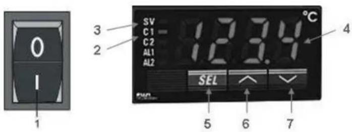
Figure 10: Heater-control section.
The heat is turned ON and OFF by the 0/I switch (1). Press I to turn the heat ON. The actual roll temperature (4) is shown on the control display. The heat has a factory defined temperature range. Within this range the roller temperature can be regulated. The temperature set point is displayed when the SEL (5) button is pressed, and changed by pressing the up (6) or down (7) buttons.
Note: When the temperature set point is being displayed, the light by SV (3) is lit. Press the SEL (5) button again to return to the actual temperature or the display will return back automatically in about 20 seconds.
If the actual temperature is lower than the set point temperature, the heat is turned ON and C1 (2) is lit.
Note: The heated roller needs time to reach its set temperature (e.g. from room temperature to maximum takes approximately 1 hour). It is recommended to let the machine run at a low speed, to avoid uneven hot spots.
5.1.3 Additional controls
Figure 11: Additional controls
Emergency stop buttons (1), push and hold button;
When pressed the rotation of the rolls is stopped immediately and the button is locked into this stop position.
Turn the button to unlock it.
Pressing start, reverse or pressing the footswitch starts the process again.
Nip setting wheel (2), geared wheel;
Turn the wheel clockwise to narrow (close) the nip or
counter-clockwise to widen (open) the nip.
When both rollers touch the materials, the pressure is set. By turning the wheel clockwise the pressure is increased. Turning the nip setting wheel counter-clockwise the pressure will decrease.
The nip setting and the pressure are indicated on the control panel.
Foot switch (3), snap switch;
Press and hold the switch to start the rotation of the rolls. Insert the forefoot completely to disable the safety lock that prevents accidental starting.
When the switch is released, the rotation of the rolls will stop.
Unwind tension control (4), knob;
By turning this knob clockwise an amount of friction is set between the shaft and the frame, so this will act as a brake.
Tightening the brake will apply more tension to the material on the shaft.
Turning the knob counter-clockwise will release the brake and therefore release the tension.
Unwind/wind-up tension control (5), knob;
By turning this knob clockwise an amount of friction is set between the shaft and the frame, so this will act as a unwind brake.
Turning the knob counter-clockwise will release the brake.
Turning the knob further counter-clockwise will set an amount of friction between the shaft and the driving sprocket wheel, so this will act as a coupling between motor and shaft. The shaft will now act as a wind-up shaft.
Turning the knob clockwise will release the wind-up shaft again.
Wind-up tension control (6), knob;
By turning this knob clockwise an amount of friction is set between the shaft and the driving sprocket wheel, so this will act as a coupling between motor and wind-up shaft.
To release the tension, turn the knob counter-clockwise.
In-feed table (7)
The standard in-feed table can swing up around the pivot point at the top of the table arms.
The image guide is attached to the input table and can be removed by shifting it from underneath its retaining knobs.
Easy-feed table (option)
The Easy-feed table replaces the standard in-feed table when initially ordered from factory.
Figure 12: Easy-feed table controls
The Easy-feed table can swing up around pivot point (P) till it is upside down. In the upper position it is stopped by the shaft supports and in the lower position by the table stops (M).
The in-feed table has a number of features to help feeding images correctly. Some of these features can only be used in some of the processes.
The features and their controls (A to M) are described below.
Media trough (A)
To unwind a medium from a roll.
The trough can swing to the front (left) to be used or to the bottom rear (right) to be out of the way.
When the trough (A) is in position it is locked with a detent (B).
Media guide (C)
To help feeding in the medium straight the media guide can be set to one side of the medium.
Easy-feed rollers (G)
Another aid to feed-in the medium straight are the in-feed rollers.
These rollers can not be used when processing panels and must be moved out of the way by pulling down the handle (D). The centre of rotation is the shaft of the lower roller. The upper roller moves into the table, where it replaces the table element (H).
The upper roller can be lifted from the bottom roller with the handle (E) which rotates an excentric (F) on the shaft. The flattening allows the upper roller to rest on the bottom roller.
On the right side of the bottom in-feed roller a brake is installed that can be set by a small handwheel (G). With this brake tension can be set to the medium. Turning the wheel clockwise sets the tension and counter-clockwise releases the tension.
Image guide (I)
The image guide (I) is fixed to the in-feed table, but can be moved out of the way. It slides through a groove (K) in the table arm and can be pulled back and stored in the storage place underneath the table surface.
The storage space for the image guide is covered by a flap (L) when the guide is in use.
Note: When the image guide is in use and the nip is zero, the optical safety device 'looks through' holes (J) in the guide ends.
Note: When the nip is not set to zero the light-beam of the safety device will be interrupted by the image guide. Therefor the image guide must not be used (and stored away) when processing panels.
5.1.4 Error indications
When an error is detected, one or more LED's are flashing and any rotation will stop.
Power indicator flashing;
Machine is in stand-by mode. The power is on and the optical safety device is active.
Press the control ON/OFF button to activate the machine.
Forward indication flashing;
Motor overload.
Press the stop button and check the material flow and the tension setting of the unwind shafts.
Reverse indicator flashing;
Motor overload.
Press the stop button and check the material flow and the tension setting of the wind-up shafts.
Forward and reverse indicator flashing;
System error.
Disconnect and then reconnect the power. If the error persists, contact your service organization.
All four pressure indication LED's are flashing;
Pressure too high or nip setting too narrow.
The LED's start flashing at 10% overload. When the pressure exceeds a 20% overload an audible signal is generated. Increase the nip to lower the pressure.
5.2 Operating modes
The machine is either in normal mode, or slow mode. In both normal and slow mode the rollers can rotate in forward or in reverse direction.
5.2.1 Normal mode
When slow mode is not activated (normal mode), the rotation speed of the rollers is set via the speed control knob.
Start rotation by pressing the forward button, the reverse button or the footswitch.
Rotation stops when a stop button is pressed or the footswitch is released.
Note: To return control from the footswitch to the control panel without stopping, press and hold the forward button, release the footswitch and then release the forward button.
An interruption of the light beam of the optical safety device in front of the rollers will also stop the rotation of the rollers. To continue after the interruption is taken away, the process must be started again.
Reverse

WARNING:
KEEP CLEAR OF THE REAR SIDE NIP WHEN RUNNING IN REVERSE MODE.
When running in reverse, the optical safety device at the front side nip is ignored and the optical safety device at the output side is active. The speed is determined by the speed control.
5.2.2 Slow mode
Enter or leave Slow mode by pressing the slow mode button for 1 second. The selection is indicated by the slow mode indication LED. Entering slow mode will not change anything to the current movement of the rollers.
In slow mode the rollers can run at normal or at slow mode speed.
Normal speed
Press the forward or reverse button in slow mode to run at a normal speed determined by the speed control setting (see normal mode).
To start at slow mode speed or to switch from normal (forward) to slow mode speed just press and hold the footswitch (when slow mode is selected).
Slow mode speed
Press and hold the footswitch in slow mode to force the rollers to run forward at a fixed low speed (see specifications) independent from the speed control.
Slow mode speed is always running in forward direction. Slow mode speed in reverse direction is not possible.

WARNING:
KEEP CLEAR OF THE NIP WHEN RUNNING AT SLOW MODE SPEED.
When running at slow mode speed, the optical safety devices are ignored.
When the footswitch is released, the forward rotation is stopped.
Note: To change from slow mode speed to normal speed without stopping, press and hold the start button, release the footswitch and then release the start button.
Changing to normal speed will not deactivate slow mode.
Pressing the footswitch again will slow down rotation to slow mode speed again.
5.3 Placing film rolls
5.3.1 Auto-grip shafts
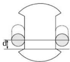
Both shafts in the front of the machine are the same. The shafts fit into the machine in both ways. Their function is determined by their position in the machine and the setting of the tension control. The shafts on the rear side can swing out of their support on the control panel side. On the other side the shaft is fixed to the machine. On the control panel side of the machine all the shafts and the supports snap together by a gripper slot and gripper. A spring inside the left-hand side support pushes the shaft into locking position when the shaft is turned. To position the shaft correctly push it firmly into the supports and turn the shaft until it locks in. Check the auto-grip mechanism on each shaft. The rubber cords should just touch the edges of the recess (Figure 13A: d = 8 ± 2.5 mm ). If not, see chapter 6 Maintenance.
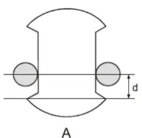
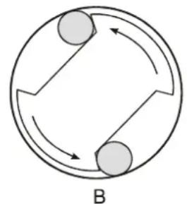

Figure 13: Auto-grip shaft
When the shaft is rotated inside a cylinder, the rubber cord will move to the side and gets caught between shaft and cylinder (Figure 13B). Rotating back will release the cord.
5.3.2 Use of films with release liner
When using a film with a release liner that must be removed, load the wind-up shaft with a scrap core (empty cardboard cylinder) of (at least) the same width as the film.
- Take the auto-grip shaft from the wind-up position of the machine.
- Place the scrap core on the shaft, holding the shaft as in Figure 13C.

CAUTION:
Do not drop the end of the shaft on the floor.
- Put the shaft with cylinder back into the machine.
- Push both sides of the shaft firmly into their supports.
- Turn the shaft until the grippers lock in.
5.3.3 Loading shaft with film rolls
The film roll is put on the shaft depending on the type of film and the use in the upper or lower section of the machine. In general pressure sensitive film with release liner (A) is rolled up with the liner (3) and adhesive (2) to the outside of the film (1), whereas film without release liner (C) has its adhesive layer to the inside of the roll. However North American pressure sensitive films in general have the release liner on the inside of the roll (B).
Figure 14: Film rolls.
- In the upper section, the adhesive (2) side in contact with the image must be on the top when unwinding the film to the front of the machine.
- In the lower section, the adhesive (2) side in contact with the image must be on the bottom when unwinding the film to the front of the machine.
Figure 15: Film adhesives.
- Swing out the auto-grip shafts from the unwind positions of the machine.
- Slide the film rolls onto the swing shafts as described above.
- Swing the shafts back into their supports and close the shaft support covers.
Unwind direction of film towards the front of the machine:
in the upper section;
- film with release liner on the outside unwinds from the top (A),
- film with release liner on the inside unwinds from the bottom (B),
- film without release liner unwinds from the bottom (C).
in the lower section;
- film with release liner on the outside unwinds from the bottom (D),
- film with release liner on the inside unwinds from the top (E),
-
film without release liner unwinds from the top (F).
-
Push both sides of the shaft firmly into their supports.
- Turn the shaft until the grippers lock in.
- Position the film and the scrap core in the middle and align them.
Operating 21
Note: When both upper and lower section are used, place both films at exactly the same position.
- Make sure the films (and scrap cores) are set up and aligned properly.
5.3.4 Use of a splitter bar
-
The splitter bar has two functions:
-
When processing film with release liner, it is used to split the release liner from the film.
- When processing heat sensitive film it is used to reroute the film to increase the contact surface with the heated roller.
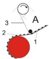
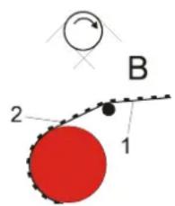
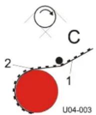
Figure 16: Use of a splitter bar.
Film with release liner (A) is running via the splitter bar where the release liner is split off. Pressure sensitive film without release liner (B) would leave adhesive remains behind on the splitter bar, so this is lead over the splitter barHeat activated film (C) needs as much contact surface with the heated roller as possible. Therefore this film is lead underneath (via) the splitter bar.
5.3.5 Presetting the tension
To enable the film to unwind without wrinkles tension (brake) can be set to the roll. On the right-hand side of the machine you will find tension control knobs, corresponding with each shaft.
Turn the tension control knob clockwise to set the tension or counter clockwise to release the tension.
Note: The unwind/wind-up shafts in the bottom half have a split tension setting: Turn clockwise for unwind tension and counter clockwise to release the unwind tension. Turning further counter clockwise will set wind-up tension (see also section 5.1.3).
When the film is webbed, it is recommended to set a low tension to each shaft by turning the knob clockwise until you feel some resistance. On the unwind shaft this will prevent film from unwinding without tension. On the motor-driven wind-up shaft it allows the shaft to slip and adapt its rotation speed to the speed of the film.
5.3.6 Pressure setting
Thin images
When processing thin images (printer output, posters, etc.) pressure is preset when the upper and lower material is webbed. When the leader panel or release board is through the nip, the nip is set to zero and pressure is preset.
The best pressure setting for thin films is about 80% .
During processing the pressure can be adjusted.
Panels
When processing panels, a leader panel is used to web the film(s). This leader panel is at the same time used to preset the pressure.
Use a leader panel of the same material, thickness and width as the panels to process.
- Set the nip to the thickness of the panel.
-
Feed the leader panel into the nip in slow mode.
-
When the edges of the film(s) are through the nip, set the pressure to approximately 80% for full-width panels.

CAUTION:
For narrower panels set the pressure proportional to the width between 40% and 80% . E.g. half width equals 60% .
Mounting boards
The panel to be mounted can be used to set the nip and pressure.
- Set the nip to the thickness of the panel.
- Feed the panel into the nip in slow mode.
- When the panel is halfway in the nip, set the pressure between 70 and 80% for full-width panels.

CAUTION:
For narrower panels set the pressure proportional to the width between 40% and 80% . E.g. half width equals 60% .
- Back-up the panel out of the nip
Note: The image will add approximately an additional 5 to 10% to the pressure.
5.4 Webbing
For most processes the machine must be webbed before images on thin film or on panels can be processed. The machine can be webbed for single sided or double sided processing.
Note: In single sided processes adhesive residues will stay behind on the bottom roller where the film is wider than the images. To prevent this, use film of the same width as the image, or a release liner of the same width as the top film can be used in the bottom section. The release liner can easily be removed later on.
In the bottom section both shaft positions are unwind/wind-up combination positions that have to be set as an unwind or wind-up position.
When processing panels, a leader panel (waste panel equal to the panels to process) is needed to feed in the film and set the pressure and tension.
When processing thin images a release board is needed to feed in the film. When this panel is through, the nip is set to zero and the images can be fed. The release board is then cleaned and can be used again.
5.4.1 Upper section only
Figure 17: Webbing upper section.
-
Remove the image guide.
-
Unwind the film from the upper or top unwind roll.
-
Feed a pressure sensitive film without release liner over the splitter bar (A).
-
Feed all other films underneath the splitter bar (B).
-
Pull the film forward until approximately 10cm (4 in.) is on the in-feed table.
If the film has a release liner:
- Peel off the release liner.
-
Pull the release liner up and stick it to the scrap core on the wind-up shaft.
-
Stick the leader panel to the film and feed the panel into the nip using slow mode.
Note: Use a release board when processing thin images without using carrier boards.
5.4.2 Upper and lower section
A release board or a leader panel of the same thickness as the panels to process is needed.
Figure 18: Upper and lower section webbed.
The film in the upper section is webbed first:
- Remove the image guide.
- Feed the film underneath (B) the splitter bar (between splitter bar and upper roller)
-
Pressure sensitive film without a release liner must be fed over the splitter bar (A).
-
Pull the film forward until it almost reaches the in-feed table and apply it to the upper roller.
If the film has a release liner (B):
- Peel off the release liner,
- Pull it up and stick it from below onto the cylinder on the wind-up shaft.
Now web the lower section:
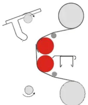
A
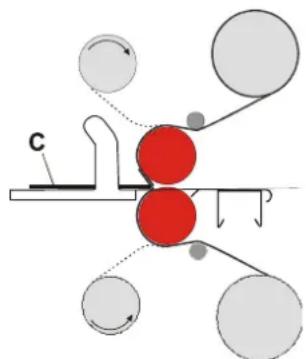
B
Figure 19: Webbing lower section.
- Lift the in-feed table and put it in the upper position (A).
-
Unwind the film from the lower unwind roll.
-
Feed a pressure sensitive film without release liner underneath the splitter bar (A),
-
Feed all other films over the splitter bar (B).
-
Pull the film forward until the end reaches above the nip and stick it to the film from the upper section.
If the film has a release liner (B):
- Peel off the release liner and pull it over the wind-up shaft,
-
Stick it from above onto the cylinder on the wind-up shaft.
-
Lower the in-feed table.
- Push the films with a leader panel (C) into the nip using slow mode (B).
Note: Use a leader panel of the same material, thickness and width as the panels to process. Use a release board when processing thin images.
5.4.3 Result to Roll or Roll to roll
When webbing for a result to roll or roll to roll (R2R) process, the lower rear unwind/wind-up shaft is used to wind-up the result.
The laminates are webbed as described above.
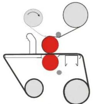
A
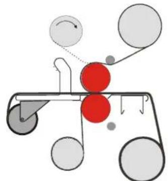
B
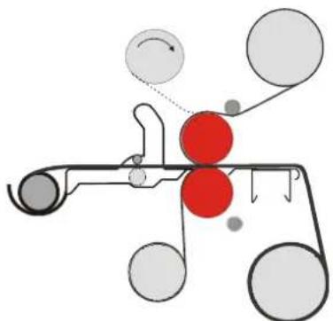
C
Figure 20: Webbing image from roll to roll.
Single sided lamination;
When laminating single sided the unwind/windup shaft in the front of the lower section can be used to unwind the images (Figure 20, A).
Double sided lamination;
The unwind/wind-up shaft in the front of the lower section is needed to unwind the botom lamination film (Figure 20, B and C).
This means in the lower section only a laminate without a release liner can be used and the Media Unwind option(B) or the media trough of the Easy-feed table (C) is needed to unwind the images.
Webbing the images;
- Web the upper and lower section laminates as described in the previous sections.
- When the release board is through the nip, cut off the board and stick the leading edge of the result onto the cylinder on the wind-up shaft.
- Set the tension control for this shaft to wind-up tension.
- Pull the image to the front and feed it over the in-feed table into the nip.
- When available, use the rollers of the Easy-feed table to enter front edge of the image roll correctly into the nip.
5.5 Processes and settings
5.5.1 Mounting images or decals
In this process the machine is not webbed with film.
- When mounting images onto a (pre-coated) board (B), the adhesive is on the mounting side of the board.
- When mounting decals (A), the adhesive is on the back of the image.
The mounting process is equal for both.
- Remove the shaft from the upper front position.
- Preset the nip and the pressure (see section 5.3.6).
- Put the board on the in-feed table.
- Put the image on top of the board (image side up). Turn back the image at the machine side (1).
- Turn back approx. 25mm (1.0 in.) release liner (2) at the machine side and crease this evenly from the inside out.
Note: The final quality depends on the way in which the leading edge of the image is applied to the board.
- Apply the image (3) to the board (C).
- Insert the edge with the image adhered to into the nip (D).
- Lay the loose end (4) of the image smoothly over the upper roller.
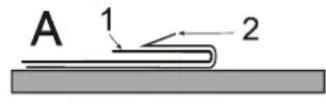
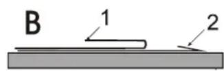
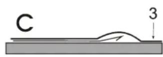
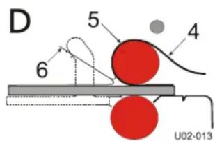
Figure 21: Mounting images or decals
Note: Use the footswitch to start/stop in slow mode, keeping your hands free.

WARNING:
KEEP YOUR FINGERS CLEAR OF THE NIP.
THE OPTICAL SAFETY DEVICE IS NOT FUNCTIONING WHEN USING THE FOOTSWITCH IN SLOW MODE.
- With your left hand - peel back the release liner (6) from the image or board as it is slowly fed into the nip one section at a time, without stopping.
Note: Removing the release liner completely exposes the adhesive to dirt and dust that will get trapped under the image.
- With your right hand - keep the image smooth against the upper roller (5), preventing the image from wrinkling.
Note: For the best result; do not stop while feeding an image.
5.5.2 Pre-coating panels
This process is used to coat boards (substrates) with a pressure sensitive mounting film onto which images can be mounted. This process can also be used to create a carrier board. In this case a film with a non-stick surface is used.
Note: The mounting film is usually provided with one release liner. Place the film in the upper section and web it as if it has no release liner (over the splitter bar).
- Place the roll of mounting film on the shaft of the upper unwind position.
- Set the nip to correspond to the thickness of the panels to be processed.
- Web the film using a leader panel of the same material, thickness and width.
- Set the pressure while feeding the leader panel.
-
Before the end of the leader panel enters the nip, butt up the panel to be pre-coated.
-
When more panels have to be pre-coated feed them in continuously without gap.
-
At the end, use a leader panel again to finish. This prevents the adhesive from touching the bottom roller.
-
End with a leader panel and feed this board until the previous panel is out of the nip.

CAUTION: Do not cut film close to or on the rollers. This will damage the silicone coating of the rollers and will void the warranty.
- Cut this panel free using a blade cutter.
- Back-up the leader panel using the reverse.
- Cut the film using a blade cutter.
After removing the release liner from the pressure sensitive mounting film, the board has an adhesive coating ready to mount an image. See section 5.5.1 for mounting images.
5.5.3 Over-lamination
After an image is mounted to a panel, a protective laminate can be applied.
This process is the same as pre-coating a board (section 0).
The over-laminate can be a heat sensitive laminate or a pressure sensitive adhesive with or without release liner.
5.5.4 Single-sided lamination
Images can be laminated single-sided with or without using carrier (or release) boards.
This laminate can be a heat sensitive laminate or a pressure sensitive adhesive with or without release liner.
Disadvantage of the single sided lamination process is the adhesive residue that can stay behind on the rollers where there is no image.
To avoid this, carrier boards or release liner can be used. Or the image must be wider than the laminate and pieces of scrap material must be used to begin and end with.
Using carrier boards:
- Web the upper section of the machine as described above (section 5.4.1)
- Put the image on a carrier board with the image side up and follow the steps for pre-coating a board (section 0).
Using release liner:
- Use a roll of release liner in the lower section.
- Web the upper and lower section of the machine as described above (section 5.4.2).
When the images are cut from the result, the release liner will separate from the image automatically.
5.5.5 Double-sided lamination
Encapsulating images with cold laminates is called double-sided lamination (and is normally not done with panels).
- Load and web laminating films in the upper and the lower section as described in section 5.4.2.
- When the leader panel is completely out of the nip, lower the upper roller onto the bottom roller (nip setting = 0) and set the pressure to approximately 80% .
- Now feed the images into the nip, allowing a gap between them.
- Cut the result with a blade cutter when the images are clear of the rollers.
5.5.6 Decaling
When decaling, a laminate is put over the image side and an adhesive backing is put on the backside of the image.
The process is the same as double-sided lamination (section 5.5.5).
- Load and web laminating films in the upper and the lower section as described in section 5.4.2.
- When the leader panel is completely out of the nip, lower the upper roller onto the bottom roller (nip setting = 0) and set the pressure to approximately 80% .
- Now feed the images into the nip, allowing a gap between them.
- Cut the result with a blade cutter when the images are clear of the rollers.
This decal can later be mounted onto a panel or other substrate.
5.6 Unloading
To unload the machine:
- Cut the result after the last image (panel before the leader panel).
- Cut both films along the splitter bar using a blade cutter.
- Open up the nip and remove the (leader panel and) films from the rollers at the rear.
To unload a roll from the shaft:
- Turn the material roll in the wind-up direction to free the autogrip cords.
- Take out or swing out the autogrip shaft.
- Remove the material roll from the autogrip shaft.
6 MAINTENANCE
6.1 Cleaning
The machine has to be cleaned regularly. Dirt and dust will have a negative influence on the result of the lamination processes.

CAUTION:
Do not use abrasive materials for cleaning the machine. This can damage the painted surfaces or the silicone covering of the rollers.
Use a damp cloth for cleaning.

CAUTION:
Make sure water does not run into any of the cabinets. This can damage the electrical circuits when power is applied.
Clean the exterior of the machine with a damp cloth as needed. If necessary, use a householdcleaning solution to remove difficult marks.
Clean the shafts and the rubber cords on it as required.
6.1.1 Cleaning the silicone covered rollers.
The rollers must be cleaned regularly to prevent a build-up of adhesive residue. This may eventually damage the rollers.
Use a damp lint-free cloth to remove dust and other dirt.
Use a silicon-cleaning block to remove the adhesive stains from the rollers.
Note:
Adhesive is easier to remove when the rollers are hot.
Put a waste panel between the rollers when cleaning the upper roller, to prevent adhesive remnants from falling onto the lower roller.

WARNING:
MAKE SURE THE ROLLERS ARE COLD WHEN USING ALCOHOL FOR CLEANING. ISOPROPYL ALCOHOL IS VERY FLAMMABLE.
Difficult stains can be removed with the aid of isopropyl alcohol (IPA) and a clean lint-free cloth.
Do not pour isopropyl alcohol directly on the machine.
6.2 Preventive maintenance
Our machines are designed in such way that they need little (preventive) maintenance in addition to the cleaning.
The following checks have to be performed:
- Auto-grip shafts with blocking cords.
6.2.1 Auto-grip shafts
Check the auto-grip mechanism on each shaft.
- The distance (d) between the rubber cords and the edges of the recess should be 8 ± 2.5 ~mm minimum (the cord must not touch the skew).
A
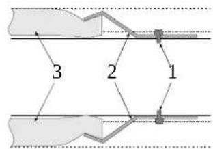
B
Figure 22: Auto-grip shaft
If not, correct as follows:
- Loosen the clamp (2) with the screw (1) until the cord is free on one side,
- Shorten the cord by approximately 10mm (0.4 in.),
- Put the end of the cord back underneath the clamp (2),
- Secure it by tightening the screw (1).
6.3 Trouble shooting
During processing wrinkles can show up in the image (1) on the in-feed table (2) and in the process result (4) on the output table. The figures below show some examples where it is caused by the main rollers (3) and gives a possible solution.
Wait until a few meters is processed to see results.
Pressure too high.
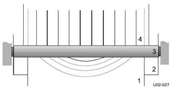
Figure 23: Wrinkles due to high pressure.
Decrease the roller pressure a little (5 - 10%)
Pressure too low.
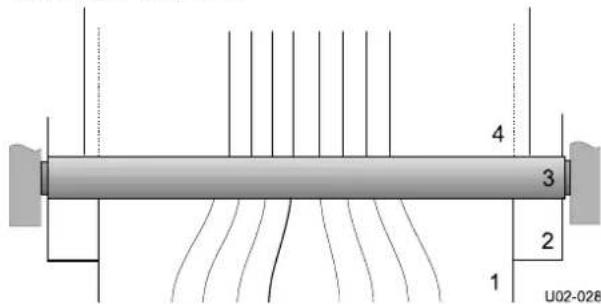
Figure 24: Wrinkles due to low pressure.
Maintenance 31
- Increase the roller pressure a little (5-10%).
Unwind tension too low.
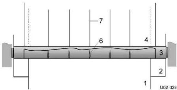
Figure 25: Wrinkles due to low unwind tension.
- Increase the unwind tension until the wrinkles (6) in the film on the roller disappear. The lines (7) in the process result will disappear as well.
Roller alignment fault.
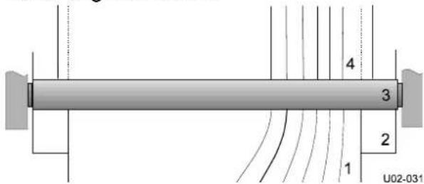
Figure 26: Wrinkles due to faulty roller alignment.
The wrinkles occur on one side only (left or right).
- This is a machine adjustment error. Contact your dealer and ask for technical assistance.
Material rolls are jumping.
A regular tick can be heard in the shaft support.
- Adjust the shaft support (1) by turning up or down the screw with an Allenkey (2).
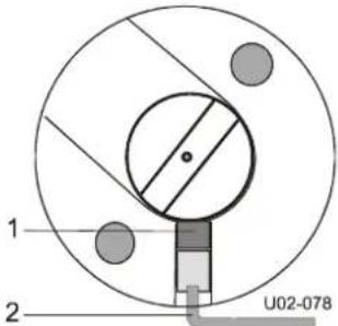
Figure 27: Shaft support adjustment.
6.4 Technical assistance
For technical assistance you can contact your dealer or the address on the copyright page in the front of this manual.
Make a clear description of the problem before contacting technical assistance.
Please keep the type and serial number of your machine at hand.
You can find this data on the identification plate of your machine, which can be found on the rear side of the right cabin
7 GLOSSARY
Carrier board or sled
A board with a non-stick surface that is used when laminating one side of an image only.
Decal
An image with an adhesive backside (Am.: Sticker).
Decaling
Providing an image with laminate on the image side and adhesive on the backside.
Encapsulating
Sandwiching an image between two heat sensitive films.
Laminate
A thin film of clear material to be permanently affixed onto an image.
Laminating
Providing an image with a thin film of clear material.
Leader panel
A (waste) piece of rigid foam board with the same specifications as the panels to process. It is used to lead film into the nip of the main rollers and to set the pressure.
Main rollers
A set of two silicone coated rollers that perform the actual process.
Mounting
Permanently affixing an image onto a backing board.
Mounting film
Adhesive backing to make an image self-adhesive. On the side that is in contact with the image the carrier has an adhesive with or without release liner. The carrier can function as release liner or be supplied with a second (cold) adhesive layer and release liner.
Nip
The area where the top and bottom main rollers meet is called the nip.
Pre-coating
Coating a substrate with an adhesive mounting film onto which an image can be mounted.
Release board
Thin (plastic) board with a non-stick surface on both sides. Used when webbing for non-panel processes. This board can be used more than once.
Release liner
Backing film protecting the adhesive layer of a laminate or mounting film. Once the release liner is removed, the adhesive layer becomes exposed.
Roll
A (shaft with a) cylinder loaded with film or release liner.
Roller
One part of the main element in the machine that performs the actual process (see main rollers).
Scrap core
An empty cardboard cylinder left over when all material on a roll is used.
Webbing
Loading the machine with film, so that the machine is ready for processing.
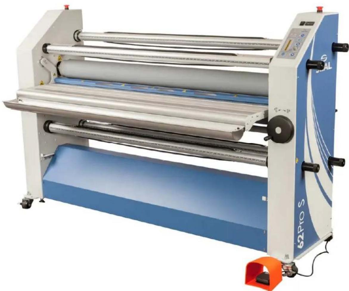
62 Pro S
Contre-collage et plastification
6.4 Assistance technique
Martyr ou plaque de support
Höhe 140.7 cm 55.4 in.
Höhe 167.5 cm 64.8 in.
Tiefe
90 cm 35.4 in.
Gewicht
540 kg
1090 lbs
Arbeitsraum:
Breite
420 cm
168 in.
Tiefe
190 cm (75 in.) + 2x maximale Plattenlange
62 Pro S (US/CAN) 2W+G 230VAC +/- 10%, 50/60Hz, 16A
Ancho 228 cm 89.8 in.
Altura 167.5 cm 64.8 in.
Desenrollado/enrollado
EC Declaration of Conformity
Manufacturers Name: ACCO Brands, USA LLC
Manufacturers' Address: 10150 80th Avenue Pleasant Prairie, WI 53158
ACCO Brands, USA declares that the machinery described below complies with all applicable health and safety requirements of Part 1 of Annex 1 of the Machinery Directive 2006/42/EC, and EMC Directive 2004/108/EC.
Confidential technical documentation has been compiled in accordance with Part A of Annex VII of Machinery Directive 2006/42/EC and is available to European national authorities on written request only. If a request is received documentation will be delivered on a CD or by post.
Machinery Description: Mounter & Laminator
Model Number(s): 62 Pro S
Specification: Laminating Machine
The following standards have either been referred to or been complied with in part or in full as relevant:
| EN ISO 12100: 2010 | Machinery Safety | Safety of machinery - General principles for design - Risk Assessment & Reduction, includes EN 14121:2007 |
| EN 13849: 2010 | Machinery Safety | Safety Related Parts of Control Systems - Part 1 General Principals for Design and Part 2 Validation |
| EN 60204-1: 2010 | Machinery Safety | Electrical Equipment of Industrial Machines - General Requirements |
| EN 1010-1:2004+A1 | Machine Safety | Safety of Machinery -Safety Requirements for the design and Construction of paper converting machines |
| EN 1010-4:2004+A1 | Machine Safety | Safety of Machinery -Safety Requirements for the design and Construction of paper converting machines |
| EN 614-2:2000+A1:2008 | Machine Safety | Ergonomic Design principals |
| EN 13850:2008 | Machine Safety | Emergency -Stop equipment Functional Aspects. Principals for Design |
| EN 61000-6-3:2007 | EMC | Generic Standards - Emission standard for residential, commercial and light industrial environments |
| EN 6100-6-1:2007 | EMC | Generic Standards - Immunity standard for residential, commercial and light industrial environments |
Full name, position of responsible person and place of signing: Tim Harper, Manager, Quality and Manufacturing Engineering,
Signature. Date: Oct. 10, 2016
Authorized EU Representative ACCO Brands (UK) United Kingdom
Contact Us:
SEAL Brands Technical Service - US & Canada
Ph: 1-800-486-6502
Fax: 1-800-966-4554
Email: tsorder@acco.com
SEAL Brands Customer Service - US & Canada
Ph: 1-800-257-7325
Fax: 1-800-966-4554
Email: csorder@acco.com
SEAL SEAL- Canada
7091 Troy Hill Drive 1601 Matheson Blvd E.
Suite B Unit #4
Elkridge, MD 21075 Mississauga, Ontario
Canada, L4W 1H9
PH: 1-800-257-7325

www.sealgraphics.com

BRANDS
ACCO BRANDS
Four Corporate Drive
Lake Zurich, IL 60047-8997
accobrandsc.com