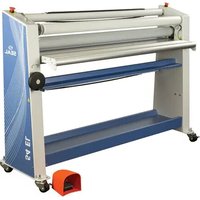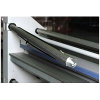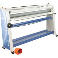
65 EL - Laminating machine SEAL - Free user manual and instructions
Find the device manual for free 65 EL SEAL in PDF.


User questions about 65 EL SEAL
0 question about this device. Answer the ones you know or ask your own.
Ask a new question about this device
Download the instructions for your Laminating machine in PDF format for free! Find your manual 65 EL - SEAL and take your electronic device back in hand. On this page are published all the documents necessary for the use of your device. 65 EL by SEAL.
USER MANUAL 65 EL SEAL
natural_image
3D rendering of a blue industrial machine with metal frame and roller, labeled '54 EL' and 'SEAL' (no text beyond labels)User manual
"A" Version
OM54-65EL-A, Rev. A
June, 2015
Introduction
We would like to thank you for purchasing a SEAL® 54/65 EL, designed to give you many years of reliable service. By following the guidelines outlined in this manual for proper care and use, you can depend on many years of trouble-free profitability from your investment.
Your 54/65 EL laminator meets the CE Directives (2004/108/EC, and 2006/95/EEC) and is RoHS compliant. The laminator is also ETL listed for USA (UL 60950-1) and Canada (CSA C22.2 60950-1).
Statement of intended use.
The 54/65 EL laminator has been designed to be used with Seal® materials. When used with these products, you are able to mount and laminate. Your machine has not been tested with any other materials and is not recommend for use with products other than SEAL® supplies.

WARNING:
THIS MACHINE IS DESIGNED FOR MOUNTING AND LAMINATING. ANY USE OTHER THAN THE INTENDED MAY CAUSE DAMAGE TO THE MACHINE OR PHYSICAL HARM TO THE USER.
Liability Statement
The details given in this manual are based on the most recent information available to us. They may be subject to change in the future. We retain the right to make changes to the construction or the design of our products without accepting any responsibility for modifying earlier versions previously delivered.
Standardized Symbols
Passages marked this way offer an idea / tip or other information on the efficient use of this unit.

WARNING:
PLEASE PAY ATTENTION TO ALL PASSAGES MARKED THIS WAY. THIS INFORMATION IS VITAL TO PREVENTING USER INJURY AND / OR DAMAGE TO THE UNIT. FAILURE TO FOLLOW THIS INFORMATION COULD VOID THE USER'S WARRANTIES AND TRANSFER ALL SAFETY OBLIGATIONS TO THE USER.
Table of Contents
Introduction 1
1 Specifications 4
1.1 Technical Specifications 4
1.2 Options 5
2 Safety / Important Safeguards 5
2.1 Safety symbols used on the equipment 5
2.2 Emergency Stop Buttons 5
3 Unpacking and Installation 6
3.1 Ambient Conditions 6
3.2 Surroundings 6
3.3 Power supply 6
3.4 Workspace Requirements 6
3.5 Unpacking the laminator 7
3.6 Setting up the laminator 8
3.7 Transport 9
4 Unit description 10
4.1 Control panel 11
4.2 Motor control 11
4.2.1 Slow-mode 12
4.2.2 Reversing the machine 12
4.2.3 Unwind brakes 13
4.2.4 Roller nip settings 13
4.2.5 Image guide storage place 13
5 Application Processes 14
5.1 Principle of a Process 14
5.2 Loading the machine 15
5.2.1 Removing an unwind shaft 15
5.2.2 Loading shaft with film rolls 15
5.2.3 Loading the unwind shaft into a machine 16
5.3 Webbing the films 16
5.3.1 Preset the tension 16
5.3.2 Single Sided Process Webbing 17
5.3.3 Double Sided Process Webbing 18
5.4 Processes and settings 19
5.4.1 General 19
5.4.2 Pre-coating panels 19
5.4.3 Mounting images or decals 20
5.4.4 Over-lamination 21
5.4.5 Single-sided lamination 21
5.4.6 Decaling 22
5.5 Unloading 22
6 Cleaning/maintenance 22
6.1 Cleaning the silicone covered rollers 23
6.2 Preventive maintenance 23
6.2.1 Auto-grip shafts 23
7 Troubleshooting 24
7.1 Troubleshooting Processes 24
7.2 Technical assistance 25
8 Process Control Sheet 26
9 Glossary of Terms 27
10 Limited Warranty 28
11 Index 29
1 SPECIFICATIONS
1.1 Technical Specifications
| Imperial Metric | ||
| Max. Working Width | ||
| 54 EL 54" maximum 1400 mm max | ||
| 65 EL 65" maximum 1651 mm max | ||
| Max. Speed 13.1 ft/min 4.0 m/min | ||
| Dimensions (HxWxD) | ||
| 54 EL 48" x 71.3" x 24" 1220 x 1811 x 610 mm | ||
| 65 EL 48" x 82.3" x 24" 1220 x 2090 x 610 mm | ||
| Shipping dimensions (HxWxD) | ||
| 54 EL 58" x 74" x 29" 1473 x 1880 x 737 mm | ||
| 65 EL 61" x 88" x 30" 1549 x 2235 x 762 mm | ||
| Weight | ||
| Net Weight | ||
| 54 EL | 325 lbs | 147 kg |
| 65 EL | 430 lbs | 195 kg |
| Shipping Weight | ||
| 54 EL | 434 lbs | 197 kg |
| 65 EL | 544 lbs | 247 kg |
| Maximum roll diameter | ||
| Unwind | 8" | 200 mm |
| Take-up | 6" | 150 mm |
| Maximum roll weight | ||
| Unwind | 85 lbs | 38.5 kg |
| Take-up | 35 lbs | 15.9 kg |
| Roller Opening (Min. - Max.) | 0 - 1" | 0 - 25 mm |
| Roller Pressure | 3 lb/in | 0.53 N/mm. |
| Electrical Specifications | ||
| US/Canada | 115 VAC, 50/60Hz, 4A, 460W - NEMA 5-15 Plug | |
| Europe | 230 VAC, 50/60Hz, 2A, 460W - BS1363 Plug or Continental Europe Plug (Schuko style) | |
| Roller Construction | Two silicone covered, steel rollers. | |
* Specifications may change without notice.
1.2 Options
The 54/65 EL "A" version has several options available. They are:
| Item Description Part number | ||
| 1 | 54 EL Infeed Trough Option | 5402A |
| 2 | 65 EL Infeed Trough Option | 6502A |
| 3 Leveling feet Option 5406A | ||
| 4 | 54 EL-1 Image Guide | 5411A |
| 5 | 65 EL-1 Image Guide | 6511A |
Note: Some options may be included with your model.
2 SAFETY / IMPORTANT SAFEGUARDS
2.1 Safety symbols used on the equipment

ROTATING PARTS
MECHANICAL HAZARD. FAILURE TO USE CAUTION NEAR EXPOSED ROLLERS COULD RESULT IN PHYSICAL INJURY. BE CAREFUL THAT ITEMS SUCH AS LOOSE CLOTHING, LONG HAIR AND JEWELRY DO NOT BECOME ENTANGLED IN ROTATING PARTS.

ESD WARNING
USE CAUTION NEAR ROLLERS. POSSIBILITY OF SHOCK BY ESD WITH SOME MATERIALS. PLEASE USE PRECAUTIONS TO PREVENT ESD BUILD UP BY PROPER MACHINE GROUNDING, MAINTAINING PROPER ROOM HUMIDITY AND USING OTHER ANTI-STATIC MEASURES.
text_image
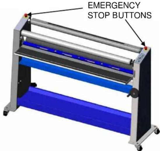
EMERGENCY STOP BUTTONSFigure 1
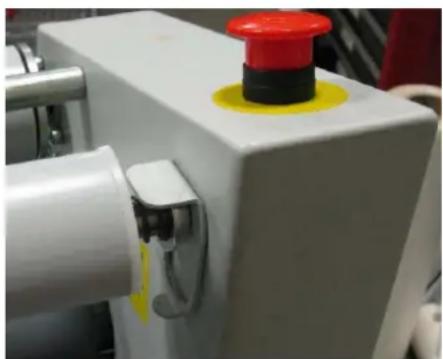
2.2 Emergency Stop Buttons
There are two buttons. They are located on the top of the left and right hand cabinets. The buttons are red with a yellow, circular background. The Emergency stop buttons shut down the rotation of the rollers and should only be used in case of an emergency. Once pressed, these buttons lock, and they must be rotated to be reset before the machine can be used again.
3 UNPACKING AND INSTALLATION
Please read and fully understand the entire manual before proceeding to use your laminator.
3.1 Ambient Conditions
The following environmental conditions are ideal for the best operation of the laminator.
Ambient Temperature
The best temperature for the 54/65 EL is between 16°C and 35°C (50°F and 95°F).
Do not expose the laminator to direct sunlight as output quality may be affected.
Relative humidity
For best results, the ambient relative humidity for the 54/65 EL should lie between 50% and 70%.
Water and moisture
If the laminator is installed in a damp room or near water, the electrical power supply must be in accordance with the standards of the area.
3.2 Surroundings
Install the laminator in surroundings that are as clean and dust free as possible in order to obtain the highest quality end product. The materials that are used on this laminator can have an electrostatic charge and will attract dust, adversely affecting the output.
3.3 Power supply
Connect the machine in accordance with the details given on the identification plate attached to the rear of the machine. Refer also to the technical specifications in this section for more information.
3.4 Workspace Requirements
- This unit should be situated away from heat sources such as heat registers or stoves.
- The laminator's location or position should not interfere with its proper ventilation.
- There should be enough space around the laminator to feed-in, exit, and trim mounted and/or laminated images.
- The background dust level must not exceed that found in a typical office/computer room environment.
- The work area should be level, flat, and well lit.
3.5 Unpacking the laminator
- Cut the bands holding the box to the pallet.
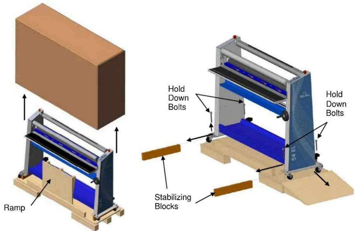
- With two people, carefully lift the box straight up over the machine (See figure 2).
- Remove any loose packing material.
- Remove two wood screws holding ramp in place.
- Remove the ramp and packing around ramp.
- Position ramp as shown in figure 3.
- Remove 4 hold down bolts.
- Remove 2 stabilizing blocks.
- With 2 people, carefully push machine down ramp.
- Remove remaining packing material and unpack the Take-up Tube.
- Inspect the machine for any physical damage.
text_image
Ramp Hold Down Bolts 54 EL Hold Down Bolts Stabilizing BlocksFigure 2 Figure 3
3.6 Setting up the laminator
Your 54/65 EL should be setup at the place where it will be used. The area must be a flat level surface.
The machine must be installed next to a power outlet. The plug and the outlet must be easily accessible. Please ensure that you plug your laminator into a grounded outlet. The laminator should only be connected to a power supply outlet able to safely supply the voltage and amperage marked on the ratings label.
text_image
S S L L S U04-030Note:
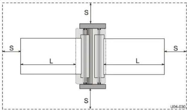
Make sure that the machine, in its final location, has adequate space. You will need room to feed, receive and trim images. See Figure 4.
L = Maximum board length,
S = Minimum space 60 cm.(24").
Figure 4: Working Space
-
Move the machine to the designated working space.
-
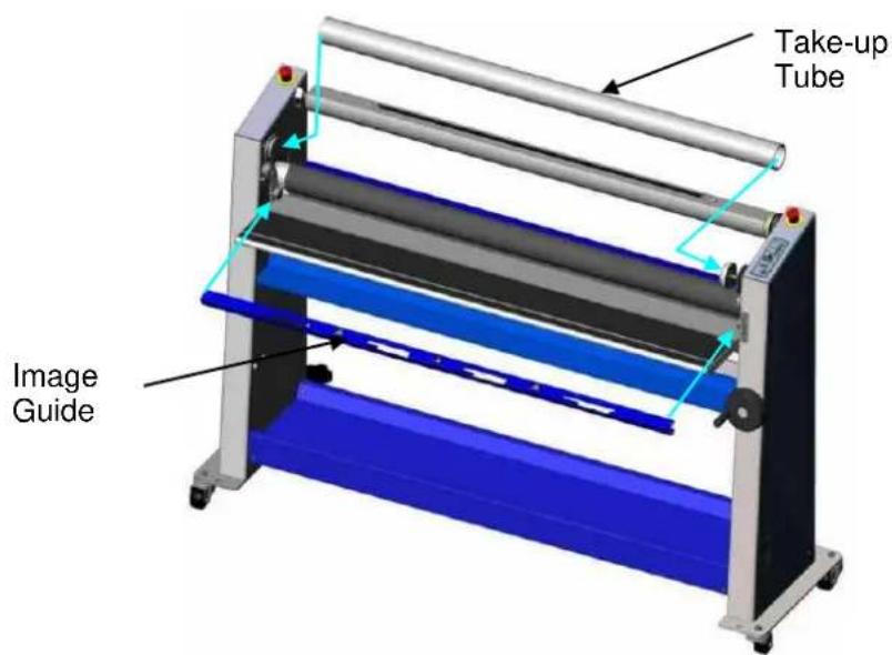
Install Image Guide on table as shown in figure 5.
Note: Image Guide is optional on some models.
-
Install Take-up Tube onto right side first compressing spring on the right side then inserting left side onto drive (figure 5).
-
Plug the power cable into the grounded outlet with appropriate service.
text_image
Take-up Tube Image GuideFigure 5
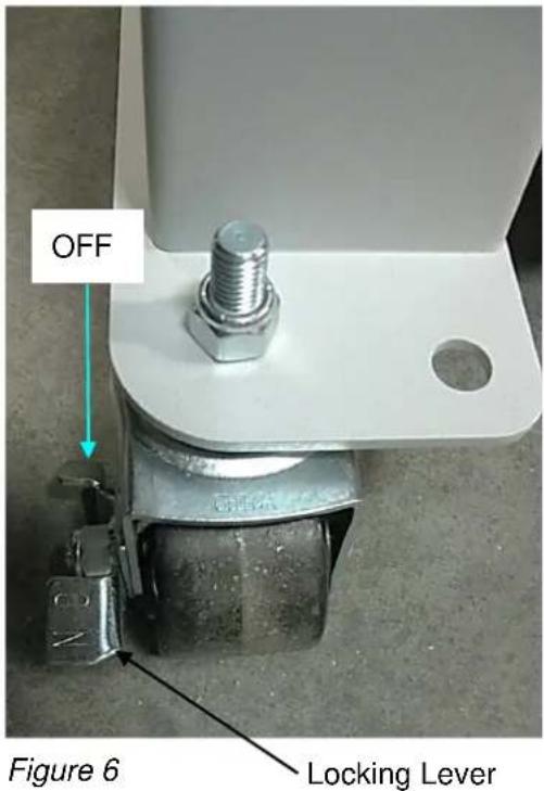
- Lock machine in place with foot by stepping on the front caster's locking mechanisms. (See figure 6.)
Note: An uneven floor may affect lamination quality. In the case of an uneven floor, please contact technical service for the machine leveling option.

WARNING:
MACHINE MUST BE SECURED IN PLACE BEFORE USING.
text_image
OFF Figure 6 Locking Lever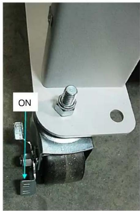
text_image
ON
WARNING:
MAKE SURE THE POWER SUPPLY CABLE AND/OR THE EXTENSION CABLE IS NOT BLOCKING YOUR WAY AROUND THE MACHINE.
3.7 Transport
The machine can be transported on a smooth surface on its casters.
CAUTION:
Unlock the wheels before moving the machine.
When moving the machine on rough surfaces or over long distances, use the original pallet and packing material and move it with a pallet truck or forklift.
4 UNIT DESCRIPTION
Features and benefits of the 54/65 EL:
2
4 5
1
3
10
6
8
7
9
Figure 7
Identification of parts
1 Wind-up tube Wind-up for the release-liner
2 Emergency stop buttons To stop machine in case of emergency
3 Image guide To help start images (Optional on some models.)
4 Upper unwind shaft The shaft is suitable for material with a 3-inch core
5 Unwind brake A simple means of setting the unwind tension
6 Control panel Controls rotation of the rolls and standby
7 Nip Hand Wheel To adjust the gap between the rollers
8 Lower unwind shaft The shaft is suitable for material with a 3-inch core
9 Foot switch Used to engage slow mode
10 In-feed Table Flat surface to rest material to be worked on
The Ratings/Serial label is located on the rear side of the machine by the power inlet.
4.1 Control panel

text_image
Diagram of a control panel with labeled buttons and rotary indicators, numbered 1 to 9.Figure 8
| 1 Forward LED Lit when drive runs forward | |
| 2 Forward Button Push button for forward | |
| 3 LED optical safety system | Lit when light beam is clear.Flashing when emergency stop button depressed. |
| 4 Stop Button Push button to stop drive | |
| 5 Reverse LED Lit when drive runs reverse | |
| 6 Reverse Button Push button and hold for reverse | |
| 7 Speed adjustment knob | Adjust roller speed |
| 8 Standby Button Toggle on/off (press 2 seconds) | |
| 9 Power LED Lit when machine is on | |
4.2 Motor control
The speed of the rollers is continuously adjustable between 0 and 4 m/min (0 and 13 ft/min). Pressing the ↑ button runs the rollers in forward direction, pressing and holding the ↓ button reverses the direction of the rollers. The stop key halts the roller movement.

WARNING:
CARE MUST BE TAKEN NOT TO HAVE LOOSE CLOTHING, LONG HAIR, JEWELRY AND FINGERS PINCHED BETWEEN THE ROLLERS.
4.2.1 Slow-mode
The machine has a slow-mode, which can be activated by pressing the foot switch. To maintain slow-mode, keep the foot switch pressed. Slow-mode must be used when the In-feed Table is in the upper position. Slow mode is recommended whenever running material with the Image Guide removed.
The speed can be adjusted when running in slow mode. The speed can be adjusted down to zero, but cannot be adjusted any higher than maximum allow in slow mode (1 mpm or 3 fpm). The position of the speed pot will be about the same as in normal mode to produce the same speed. Another benefit to this feature is the speed will not increase if going slower the preset maximum speed when entering slow mode.

WARNING:
IF RUNNING IN SLOW-MODE, INTERRUPTING THE PHOTO ELECTRIC EYES DOES NOT STOP THE MACHINE. IN SLOW-MODE, AN AUDIBLE BEEP WILL BE HEARD, AND THE ROLLER SPEED WILL BE DECREASED. RELEASING THE FOOT SWITCH STOPS THE MACHINE.
To Change from slow-mode to normal run mode without stopping (to prevent a stop mark):
- During slow mode (keep the foot switch pressed), press and hold the ↑ (forward) button on the control panel.
- Next, release the foot switch. The machine will run at the pre-set speed.
- Finally, release the ↑ (forward) button.
To Change from normal run mode to slow-mode without stopping:
- Press the foot switch
Note: Releasing the foot switch will stop the machine.
4.2.2 Reversing the machine

WARNING:
KEEP CLEAR OF THE REAR SIDE NIP WHEN RUNNING IN REVERSE MODE.
To reverse the rotation of the rollers, press the ↓ (reverse) button. As long as the button is pressed, the machine will run in reverse direction, at a speed of about 1 m/min. Releasing the button will stop the machine.
The rotation of the rollers will stop when:
- The photoelectric eyes in front of the main rollers are interrupted.
Note: This does NOT happen when the foot switch is used (slow-mode). - An emergency stop button is pressed.
- The foot switch is pressed for a short moment.
-
The stop button on the control panel is pressed.
-
Excessive unwind tensions are set (the motor will be shut off electronically and the forward LED will blink, press the stop button on the control panel to reset).
4.2.3 Unwind brakes
Tighten the unwind brake so that it applies sufficient tension to laminate. Turning the knurled brake collar in a counter-clockwise direction increases the breaking tension applied on the laminate. Turning the collar clockwise decreases the tension. The best setting for the brake tension is determined by the materials you are using and is learned through experience.
4.2.4 Roller nip settings
Whenever you mount onto a board, etc., it is important to adjust the rollers to create a gap nearly equal to the thickness of the substrate being used. This is done so that anything passing between the rollers will receive the right amount of pressure to prevent damage to the substrate being mounted (and possibly the rollers).
Turning the Nip Hand Wheel counterclockwise (CCW) lowers the top roller, and clockwise (CW) raises the top roller.
How to set the nip:
Determine the thickness of the substrate that you will use for mounting. Pre-set the nip height by turning Nip Hand Wheel CW until the nip height indicator is above the board thickness.
Insert the front edge of the substrate into the nip by hand. Lower the top roller by turning the Nip Hand Wheel CCW until top roller contacts the substrate with enough pressure that the substrate cannot be moved side to side. Use reverse button to remove substrate from nip if needed.
To run films, rotate the nip hand wheel CCW until the nip is fully closed then continue until the Nip Hand Wheel turns freely.
4.2.5 Image guide storage place
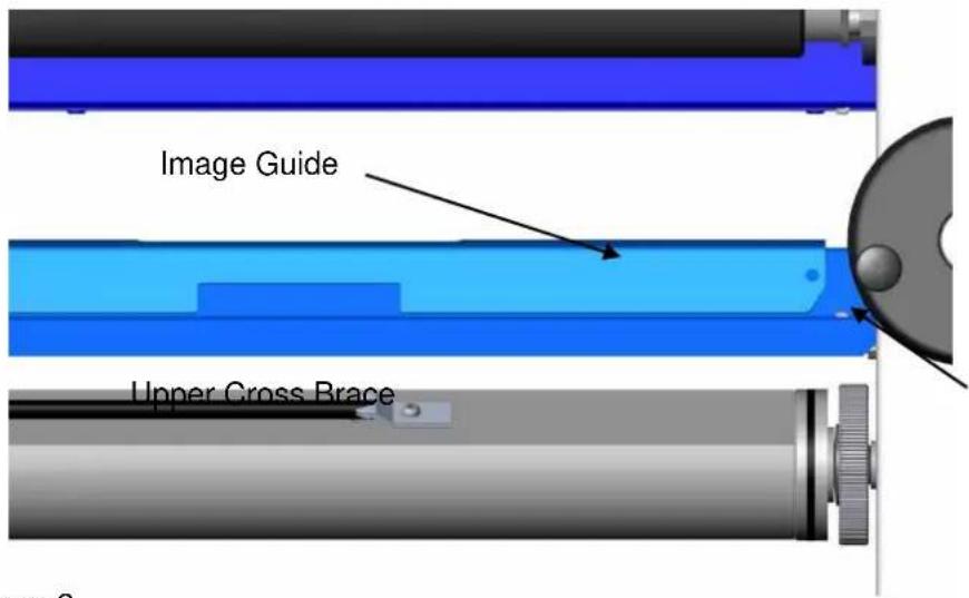
When not in use, the Image Guide can be stored on the upper cross brace or alternately on the lower cross brace(figure 9). Note: Image Guide is optional on some models.
text_image
Image Guide Upper Cross BraceFigure 9
5 APPLICATION PROCESSES
5.1 Principle of a Process
In all processes the materials are fed through the nip from the front side to be joined together by pressure.
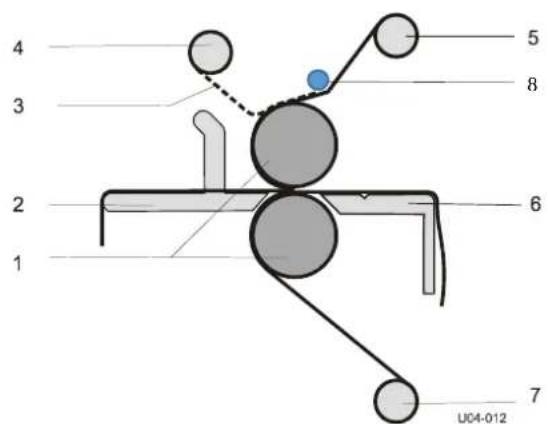
A process that makes maximum use of the machine is shown in Figure 10. Shown is a double sided laminating (decaling) process.
The top coating film is a pressure sensitive film with release liner (3) taken from a supply roll on the (rear) upper unwind shaft (5). The bottom coating film is a pressure sensitive (mounting) film taken from a supply roll on the lower unwind shaft (7). Some models have a splitter bar (8) to help in the removal of release liners.
text_image
4 3 2 1 5 8 6 7 UC04-012Figure 10: Creating a Decal.
The image that has to be laminated is fed between the main rollers (1) via the in-feed table (2). When using a pressure sensitive laminate, it often has a release liner (3) that has to be removed. This release liner is rolled up onto the wind-up shaft (4) in the upper section.
A mounting film has adhesive on both sides and release liner on just one side. This release liner has to stay on until the image is mounted.
The following steps outline the basic procedure that has to be used for loading materials, webbing the laminator and setting the brake tension for the materials you will be using. To load and unload the material shafts, it is necessary to access the machine from the rear side.
5.2 Loading the machine
Select the film(s) that you will use on the top (and bottom) of the images. It is best practice to make sure that both laminate and media are matched in size to prevent problems when laminating. This way the media can be trimmed with a border, but waste is reduced.

Always work in the center of the machine.
natural_image
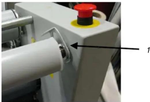
Close-up of a mechanical component with a red and yellow knob, showing a white roller and metal rail (no text or symbols visible)Figure 11: Interlock up
natural_image
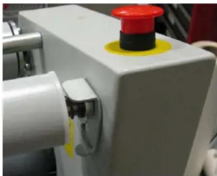
Close-up of a white industrial machine with a red and yellow button on top (no visible text or symbols)Figure 12: Interlock down
5.2.1 Removing an unwind shaft
- Remove the desired supply shaft (top or bottom) by pushing the interlock bracket (1) to the up position (Figure 11).
- Slide the autogrip shaft to the right against the spring pressure.
- Lift the leftside of the shaft away from the laminator first then the right.
5.2.2 Loading shaft with film rolls
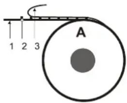
The film roll is put on the shaft depending on the type of film and the use in the upper or lower section of the machine. In general, pressure sensitive film with release liner (A) is rolled up with the liner (3) and adhesive (2) to the outside of the film (1), whereas film without release liner (C) has its adhesive layer to the inside of the film. However, North American pressure sensitive films, in general, have the release liner on the inside of the film (B).
text_image
A 1 2 3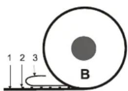
text_image
1 2 3 B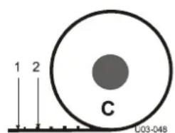
text_image
1 2 C U03-048Figure 13: Film rolls.
- In the upper section, the adhesive (2) side in contact with the image and the release liner (3) must be on the top when unwinding the film to the front of the machine.
- In the lower section, the adhesive (2) side in contact with the image must be on the bottom when unwinding the film to the front of the machine.
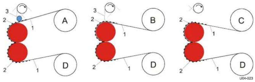
Figure 14: Film adhesives.
5.2.3 Loading the unwind shaft into a machine
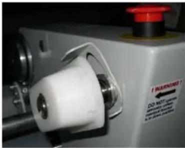
- Set interlock bracket to up position and align right shaft holder as shown in figure 15.
- Firmly grasp unwind shaft placing hands up against the ends of film roll to keep the film from sliding on the shaft while loading.
- Place the shaft, including the material, into the laminator by inserting it onto the right unwind shaft holder.
- Press against the spring pressure, until you can place the other end of the shaft onto the left unwind shaft holder.
- Move the interlock bracket is to the down position (figure 12).
- Center the material roll in the laminator.
natural_image
Close-up of a white industrial machine component with a red warning sign and circular ports (no readable text or symbols)Figure 15: Unwind Load Position.
5.3 Webbing the films
The machine must be webbed before laminating images. The machine can be webbed for single sided or double sided processing. When mounting images, the machine is not webbed.
Note: In single sided processes adhesive residues will stay behind on the bottom roller when the film is wider than the images. To prevent this, a release liner of the same width as the top film can be used in the bottom section. The release liner can easily be removed later on. Or use a film of the same width as the image.
When processing panels, a leader panel (waste panel equal to the panel to be processed) is needed to feed in the film.
5.3.1 Preset the tension
To enable the film to unwind without wrinkles tension (brake) can be set.
On the right-hand (control panel) side of the machine you will find a tension control ring on each shaft. Turn the tension control ring counter-clockwise (top to rear) to set the tension or clockwise (top to front) to release the tension.
When the film is webbed, it is recommended to set a low tension to each shaft by turning the ring counter-clockwise until you feel some resistance. The film should be tight, but able to be pulled by hand without too much effort
Too much unwind tension can lead to stress in the material and even cause wrinkling of the laminate. A properly set up machine should run film wrinkle free with minimum brake tension.

CAUTION:
Never use an open blade near the rollers. Cutting or scoring the rollers will damage the rollers and cause reduced performance resulting in low quality finished product.
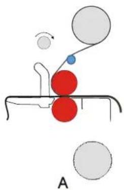
5.3.2 Single Sided Process Webbing
natural_image
Diagram of a mechanical or biological process with red and blue spheres connected by rods, no text or symbols present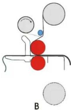
natural_image
Diagram of a molecular interaction or mechanical process with red spheres and surrounding gray spheres, labeled 'B' (no text or symbols on diagram itself)Figure 16: Webbing upper section.
-
Pull the film forward until approximately 10 cm (4 in.) is on the in-feed table.
-
If the film has a release liner (B):
• Install the Wind-up Tube on the machine.
- If your machine has a splitter tube, web the film under the tube.
- Peel back corner of release liner.
- Pull the release liner off laminate and stick it to the tube with tape.

An empty card board tube from a used roll of film can be attached to the Wind-up tube to take a release liner. This allows the release liner to be easily removed from the Wind-up tube and for other processes if needed.
-
Raise table to full open position.
-
Raise top roll to full open position.
-
From the back of machine, pull film though nip and stick to out-feed table. Ensure film is flat against top roll. Add more unwind brake if necessary.
-
If using Lower Unwind Shaft to feed images or release liner:
-
Insert material into nip making sure it is laying flat on bottom roll.
- Hold material in place with one hand.
- Lower top roll to full close (zero) position.
Note: Use a release liner on bottom unwind or a carrier board when processing thin images.
-
Lower table to the full down position.
-
If feeding cut sheet images:
-
Place a scrap piece of paper into the nip equal to width of the laminate and about 30 cm (12 in) long.
- Hold scrap piece in place with one hand.
- Lower top roll to full close (zero) position.
- Feed images over scrap piece or last image tail.
When cutting sheet images, always leave enough scrap as to have some material in the nip ing able to cut off the laminated image from the back of the machine. The film should never contact with the bottom roll.
- Pull off the film from the out-feed table (step 6) and fold down over bottom of lamination to prevent it from sticking to the table again.
- Use foot switch to start the process then switch to normal run with the forward button when ready.
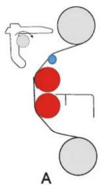
5.3.3 Double Sided Process Webbing
natural_image
Diagram of a mechanical or fluidic system with red and blue spheres connected by curved lines, labeled 'A' at bottom (no text or symbols on diagram itself)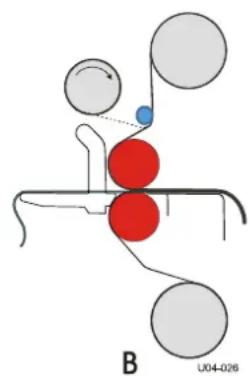
chemical
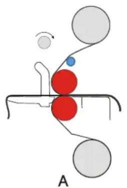
Diagram of a molecular interaction or binding process with red and blue spheres representing different components, labeled B U04-026Figure 17: Upper and lower section webbed.
The film in the upper section is webbed first
- Pull the film forward until it almost reaches the in-feed table and lay it flat on the upper roller.
- If the film has a release liner (B):
• Install Wind-up Tube on machine.
- If your machine has a splitter tube, web the film under the tube.
- Peel back corner of release liner.
- Pull the release liner off laminate and stick it to the tube with tape.

An empty card board tube from a used roll of film can be attached to the Wind-up tube to take release liner. This allows the release liner to be easily removed from the Wind-up tube and for other processes if needed.
Now web the lower section
natural_image
Diagram of a human head with red and blue circles, connected by lines and a small blue dot (no text or symbols)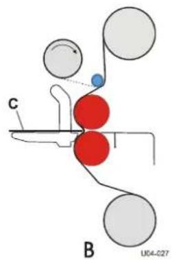
chemical
Molecular interaction diagram showing red and gray spheres representing different atoms, labeled with positions C and B, and identifier U04-C27Figure 18: Webbing lower section.
- Lift the in-feed table and put it in the upper position (A).
- Unwind the film from the lower unwind roll.
- Pull the film forward until the end reaches above the nip and stick it to the film from the upper section.
- Lower the in-feed table.
- Set nip height to about the thickness of the leader panel.
- Push the films with a leader panel (C) into the nip using slow mode (B).
- When the leader panel is completely out of the nip, lower the top roller to the full closed position (nip height = 0).
- Use foot switch to start process then switch to normal run with the forward button when ready.
5.4 Processes and settings
5.4.1 General
For up to date process information with SEAL® materials go to www.sealgraphics.com.
5.4.2 Pre-coating panels
This process is used to coat boards (substrates) with a pressure sensitive mounting film onto which images can be mounted. This process can also be used to create a carrier board (Sled). In this case a film with adhesive on both sides with a release liner is used.
Note: The mounting film is usually provided with one release liner. Place the film in the upper section and web it as if it has no release liner (see 5.3.2 for reference).
- Place the roll of mounting film on the shaft of the upper unwind position.
- Remove Image Guide.
- Raise top roll to full open position.
- Pull film through nip and attach to out-feed table.
-
Insert a leader panel into nip of the same material, thickness and width of panels to be processed.
-
Lower top roll until contacts leader panel then continue until leader cannot move freely side to side by hand.
- Butt the panel to be pre-coated up against the leader panel and use the foot switch to start the process. The drive can be put into forward run with the forward button when the process is running smoothly.
Note: When more panels have to be pre-coated feed them in continuously without gap.
-
Cut panels free using a blade cutter as they clear the nip on the back of the machine.
-
End with a leader panel, and feed this board until the previous panel is out of the nip.

CAUTION:
Do not cut film close to or on the rollers. This will damage the silicone coating of the rollers and will void the warranty.
-
When finished, back-up the leader panel using the reverse.
-
Cut the film using a safety blade cutter.
The board now has an adhesive coating ready to mount an image. See section 5.4.3 for mounting images.
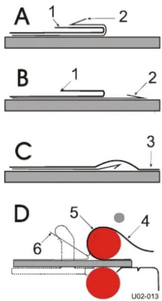
5.4.3 Mounting images or decals
In this process the machine is not webbed with film.
- When mounting images onto a pre-coated board (B), the adhesive is on the mounting side of the board.
- When mounting decals (A), the adhesive is on the back of the image.
The mounting process is equal for both.
- Remove the unwind shaft from the upper front position.
- Remove the Image Guide.
- Set the nip (see section 4.4).
- Put the board on the in-feed table.
- Put the image on top of the board (image side up). Flip back the image at the machine side (1).
- Fold back approx. 25 mm (1.0 in.) release liner (2) at the machine side and crease this evenly from the inside out.
The final quality depends on the way in which the leading edge of the image is applied to the board.
- Apply the image (3) to the board (C).
- Insert the edge with the image adhered to into the nip (D).
- Lay the loose end (4) of the image smoothly over the upper roller.
- Use the footswitch to start/stop in slow mode, keeping your hands free.
text_image
A 1 2 B 1 2 C 3 D 5 4 6 U02-013Figure 19: Mounting images or decals

WARNING:
KEEP YOUR FINGERS CLEAR OF THE NIP. THE OPTICAL SAFETY DEVICE IS NOT FUNCTIONING WHEN USING THE FOOTSWITCH IN SLOW MODE.
- With your left hand - peel back the release liner (6) from the image or board as it is slowly fed into the nip without stopping.
Note: Removing the release liner completely exposes the adhesive to dirt and dust that will get trapped under the image.
- With your right hand, keep the image smooth against the upper roller (5) preventing the image from wrinkling.

For the best result; do not stop while feeding an image.
5.4.4 Over-lamination
After an image is mounted to a panel, a protective laminate can be applied. This process is the same as pre-coating a board (section 5.4.2). The over-laminate can be a pressure sensitive lamination film.
Note: SEAL® advises to create decals (see section 5.4.6) since this better protects the print that needs to be mounted.
5.4.5 Single-sided lamination
Images can be laminated single-sided with or without using carrier boards (sled).
This laminate should be a pressure sensitive film with or without release liner.
Disadvantage of the single sided lamination process is the adhesive residue that can stay behind on the rollers where there is no image.
To avoid this, release liner or carrier boards can be used. Or the image must be wider than the laminate and pieces of scrap material must be in the nip to start or end the process.
Using release liner (recommended)
- Use a roll of release liner in the lower section.
- Web the upper and lower section of the machine as described above (section 5.3.2).
When the images are cut from the result, the release liner will separate from the image automatically.
Using carrier boards (sled)
- Web the upper section of the machine as described above (section 5.3.2).
- Put the image on a carrier board with the image side up and follow the steps for pre-coating a board (section 5.4.2).
5.4.6 Decaling
When decaling, a laminate is put over the image and an adhesive is put on the backside of the image.
- Load and web laminating films in the upper and the lower section as described in section 5.3.3.
- Feed the images into the nip, allowing a gap between them.
- Cut the result with a safety blade cutter when the images are clear of the rollers.
This decal can later be mounted onto a panel or other substrate.
5.5 Unloading
To unload the machine:
- Cut the result after the last image (panel after the leader panel).
- Cut both films 1" (25 mm) above roller surface using a safety blade cutter.
- Open up the nip and remove the (leader panel and) films from the rollers at the rear.
To unload a roll from the shaft:
- Take out the autogrip shaft (See 5.2.1).
- Remove the material roll from the autogrip shaft
6 CLEANING/MAINTENANCE
The machine has to be cleaned regularly. Dirt and dust will have a negative influence on the result of the lamination processes.

CAUTION:
Do not use abrasive materials for cleaning the machine. This can damage the painted surfaces or the silicone covering of the rollers.
Use a damp cloth for cleaning.

CAUTION:
Make sure water does not run into any of the cabinets. This can damage the electrical circuits when power is applied.
Clean the exterior of the machine with a damp cloth as needed. If necessary, use a household-cleaning solution to remove difficult marks.
Clean the shafts and the rubber cords as required.
6.1 Cleaning the silicone covered rollers
The rollers must be cleaned regularly to prevent a build-up of residue. This may eventually damage the rollers.
Use a damp lint-free cloth to remove dust and other dirt.
Difficult stains can be removed with the aid of isopropyl alcohol (IPA) and a clean lint-free cloth.
Do not pour isopropyl alcohol directly on the machine.

WARNING:
ISOPROPYL ALCOHOL IS VERY FLAMMABLE! THE FLASH POINT OF IPA IS 11°C (51.8°F). THE SELF-IGNITION TEMPERATURE IS 400°C (752°F).
6.2 Preventive maintenance
SEAL® machines are designed so they need little (preventive) maintenance in addition to the cleaning.
The following checks have to be performed:
• Auto-grip shafts with blocking cords.
6.2.1 Auto-grip shafts
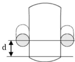
Check the auto-grip mechanism on each shaft.
- The distance (d) between the rubber cord and flat edge should be 8 ± 2.5 ~mm minimum.
text_image
dA
flowchart
graph TD
    A["1"] --> B["2"]
    B --> C["3"]
    C --> A
B
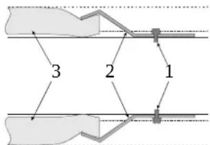
Figure 20: Auto-grip shaft
If not, correct as follows:
- Loosen the clamp (2) with the screw (1) until the cord is free on one side.
- Shorten the cord by cutting approximately 10 mm (0.4 in.) off.
- Put the end of the cord back underneath the clamp (2).
- Secure it by tightening the screw (1).
7 TROUBLESHOOTING
List of common problems and solutions that the user can correct:
| Problem cause solution | ||
| The power LED does not come on, when the machine is switched on. | There is no power Check if the power cable is plugged into the mains wall outlet. Check main power fuse by the power inlet. | |
| Both the forward and the reverse LED is flashing | The voltage from the motor power supply is too low or too high | Reset the power Call your service technician. |
| Forward LED or reverse LED is flashing | Drive-motor is in overload | Stop then restart the machine. Turn down the film tension. |
For technical assistance, please contact your technical service representative (see 8.2)
7.1 Troubleshooting Processes
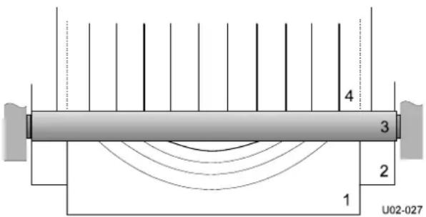
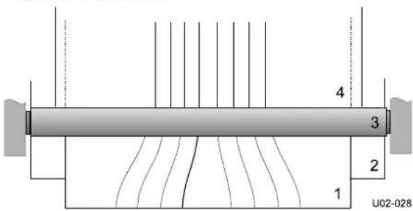
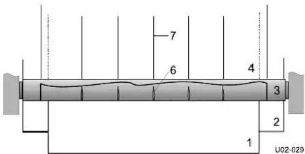
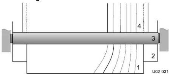
During processing wrinkles can show up in the image (1) on the in-feed table (2) and in the process result (4) on the output table.
The figures below show some examples where it is caused by the main rollers (3) and gives a possible solution.
Wait until a few meters are processed to see results.
For best results, always work in the center of the machine.
Pressure too high.
text_image
4 3 2 1 U02-027Figure 21: Wrinkles due to high pressure.
- Contact your dealer and ask for technical assistance.
Pressure too low.
text_image
4 3 2 1 U02-028Figure 22: Wrinkles due to low pressure.
- Contact your dealer and ask for technical assistance.
Unwind tension too low.
text_image
7 6 4 3 2 1 U02-029Figure 23: Wrinkles due to low unwind tension.
- Increase the unwind tension until the wrinkles (6) in the film on the roller disappear. The lines (7) in the process result will disappear as well.
Roller alignment fault.
text_image
4 3 2 1 U02-031Figure 24: Wrinkles due to faulty roller alignment.
The wrinkles occur on one side only (left or right).
- Contact your dealer and ask for technical assistance.
7.2 Technical assistance
For technical assistance you can contact your dealer or see www.sealgraphics.com for information. Make a clear description of the problem before contacting technical assistance.
Please keep the type and serial number of your machine at hand. You can find this data on the identification plate of your machine, which can be found on the rear side of the right cabinet.
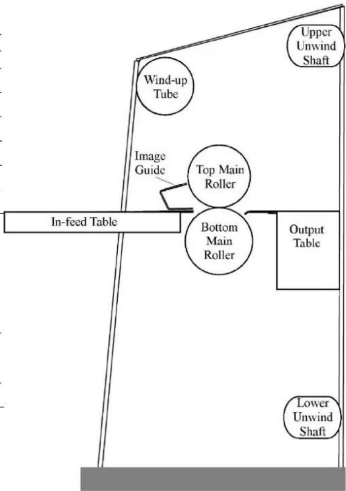
8 PROCESS CONTROL SHEET
Note: We recommend that you make a photocopy of this page. With each successfully run application, record the process and settings and a diagram of the webbing procedure. Keep the record so the application can be repeated at a later date.

If a standard image is made available for each new process then sales materials and sales can be developed for reference.
LAMINATOR SETTINGS
Media:
Process:
Application Use:
Upper Unwind Shaft:
Lower Unwind Shaft:
Wind-up Tube:
Motor Speed Setting:
WEBBING SETTINGS
Web Tension Upper Unwind Shaft:
Light / Med. / Heavy
Web Tension Lower Unwind Shaft:
Light / Med. / Heavy
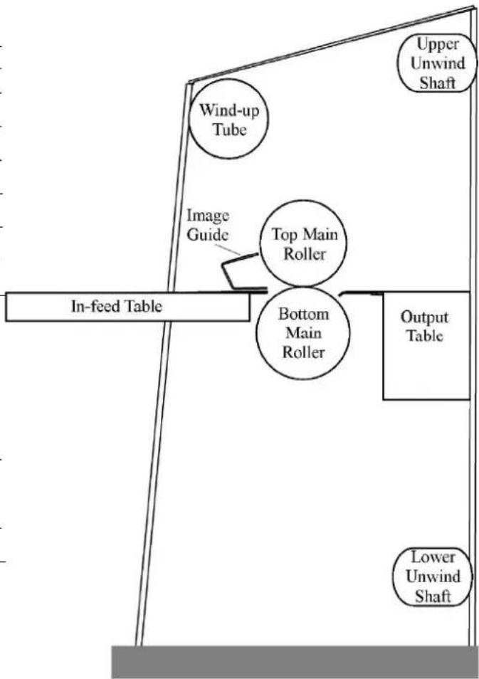
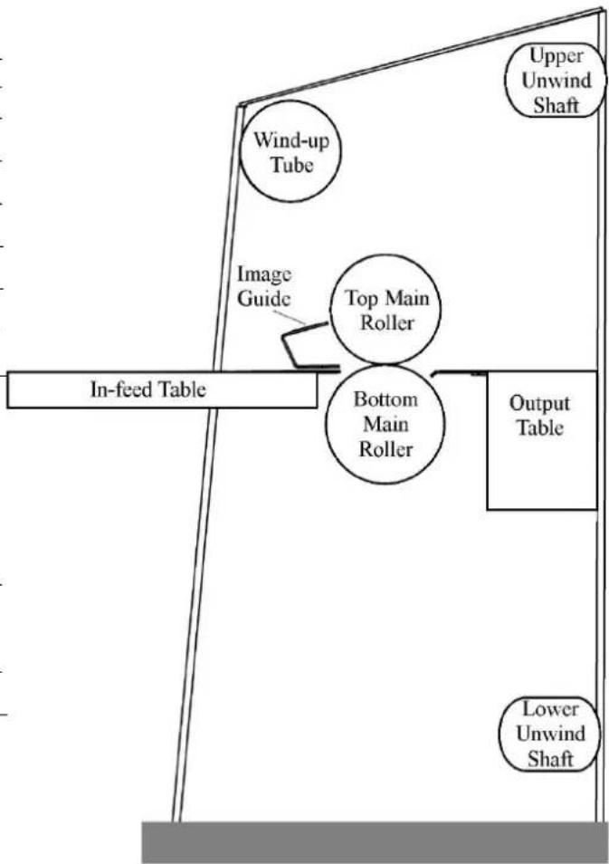
Nip Height:
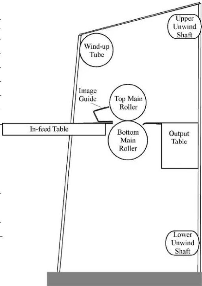
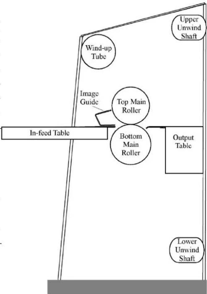
flowchart
graph TD
    A["In-feed Table"] --> B["Top Main Roller"]
    B --> C["Bottom Main Roller"]
    C --> D["Output Table"]
    E["Wind-up Tube"] --> F["Upper Unwind Shaft"]
    G["Image Guide"] --> H["Top Main Roller"]
Figure 25: Blank Webbing Diagram
9 GLOSSARY OF TERMS
Decal
An image that has been laminated on top (either heat-activated or pressure-sensitive) with an adhesive backing.
In-Feed
The side of the laminator from which images are fed.
Leader Panel
A piece of foam board about 1 m (40 in) x 10 cm (4 in) used to push films into the nip. Also used for mounting or pre-coating boards to prevent adhesive from getting onto the rollers and sealing edges.
Mil
Refers to the thickness of the laminate in 1/1000ths of an inch.
Mounting
Applying an image onto a type of foam board or substrate.
Nip
The spot where the top and bottom rollers meet.
Out-Feed
The side of the laminator from which completed images emerge.
Pre-Coating
The process of coating a substrate with an adhesive mounting film onto which an image can be mounted.
Press
The amount of force in distance put on anything that passes between the top and bottom rollers.
Pressure-Sensitive Laminates
Laminates with an adhesive, which forms a bond between the protective film and the surface of the image being laminated when applied with pressure. Used primarily for fast mounting applications and recommended for heat-sensitive thermal and photographic prints.
Release Liner
The backing on a pressure-sensitive laminate or mounting adhesive which prevents the film from sticking to itself. After peeling the release liner off, the adhesive layer becomes exposed.
Carrier Board (Sled)
A piece of smooth, non-crushable board (preferably Masonite) coated with a mounting adhesive and leaving the release liner on to provide the necessary non-stick surface. A piece of foam board can also be used, but it will not have the longevity of the Masonite board. Carrier Boards are used when laminating one side of an image only.
Substrate
The material to which an image is mounted or affixed.
10 LIMITED WARRANTY
SEAL® warrant to the original consumer purchaser that all new SEAL® laminators that prove defective in materials or workmanship within the applicable warranty period will be repaired or, at our option, replaced without charge. The main rollers are only warranted for manufacturing defects as the rollers are subject to wear and tear depending on usage of the machine. This warranty does not apply if it is found that at any time the equipment has not been used for its intended purpose.
"Original consumer purchaser" means the person whom first purchased the product covered by this warranty other than for purpose of resale. The warranty extends to and is enforceable by only the original consumer purchaser, and only for the period (during the applicable term) which the product remains in the possession of the original consumer purchaser.
The warranty printed in this manual is not binding and may not be accurate for your area. For specific information regarding the warranty, please contact your distributor or see www.sealgraphics.com.
ATTENTION!
CHANGES OR MODIFICATIONS TO THIS UNIT NOT EXPRESSLY APPROVED BY THE MANUFACTURER COULD VOID THE USER'S AUTHORITY TO OPERATE THE EQUIPMENT.
ATTENTION!
ANY UNAUTHORIZED CHANGES OR MODIFICATIONS TO THIS UNIT WITHOUT OUR PRIOR WRITTEN APPROVAL WILL VOID THE USER'S WARRANTY AND WILL TRANSFER HEALTH AND SAFETY OBLIGATIONS TO THE USER.
Note:
This equipment has been tested and found to comply with the limits for a class A digital device, pursuant to part 15 of the FCC rules. These limits are designed to provide reasonable protection against harmful interference when the equipment is operated in a commercial environment. This equipment generates, uses and can radiate radio frequency energy. If not installed and used in accordance with Owner's Manual, may cause harmful interference to radio communications. Operation of this equipment in a residential area is likely to cause harmful interference; in which case, the user will be required to correct the interference at their own expense.
11 INDEX
A
Application Processes ...... 14
D
Dimensions 4
E
Environment Conditions 6
G
Glossary of Terms ...... 27
|
Image Guide 13
interlock backet 15
L
Liability Statement ...... 1
M
Max. Speed 4
N
Nip 4
R
Roller Pressure 4
s
Speed 4
Standardized Symbols 1
W
Weight 4
wind-up idler 13
Workspace Requirements ...... 6
Introduction
7.2 Assistance technique 54
8 Process Control Sheet 55
9 Glossaire 56
Dimensions (H x I x P)
54 EL 48 x 71,3 x 24 po 1220 x 1811 x 610 mm
65 EL 48 x 82,3 x 24 po 1220 x 2090 x 610 mm
text_image
BOUTONS D'ARRÊT D'URGENCEFigure 1
text_image
S S L L S U04-030Remarque
text_image
Diagram of a control panel with labeled buttons and rotary indicators, numbered 1 to 9.Figure 8
natural_image
Close-up of a mechanical component with a red and black knob, showing a rolled paper or scroll (no visible text or symbols)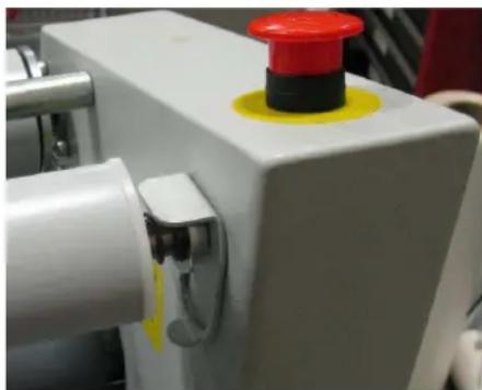
natural_image
Close-up of a white industrial machine with a red and yellow button on top (no visible text or symbols)text_image
WARNING? DO NOT: 100%100% 100% 100% 100% 100% 100% 100% 100% 100% 100% 100% 100% 100% 100% 100% 100% 100% 100% 100% 100% 100%
#1.2.2.2.2.2.2.2.2.2.2.2.2.2.2.2.2.2.2.2.2.2.2.2.2.2.2.2.2.2.2.2.2.2.2.2.2.2.natural_image
Diagram of a mechanical or fluidic system with red and gray spheres connected by rods, no visible text or symbols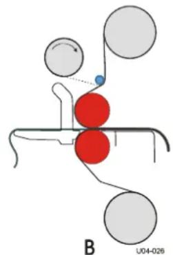
chemical
Molecular interaction diagram showing red and gray spheres representing different atoms or functional groups, with a blue dot indicating a specific site.natural_image
Diagram of a human head with red and blue circles, connected by lines and a small object (no text or symbols)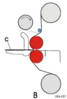
text_image
C B U04-0277.2 Assistance technique
Note: We recommend that you make a photocopy of this page. With each successfully run application, record the process and settings and a diagram of the webbing procedure. Keep the record so the application can be repeated at a later date.

If a standard image is made available for each new process then sales materials and sales can be developed for reference.
LAMINATOR SETTINGS
Media:
Process:
Application Use:
Upper Unwind Shaft:
Lower Unwind Shaft:
Wind-up Tube:
Motor Speed Setting:
WEBBING SETTINGS
Web Tension Upper Unwind Shaft:
Light / Med. / Heavy
Web Tension Lower Unwind Shaft:
Light / Med. / Heavy
Nip Height:
flowchart
graph TD
    A["In-feed Table"] --> B["Top Main Roller"]
    B --> C["Bottom Main Roller"]
    C --> D["Output Table"]
    E["Wind-up Tube"] --> F["Upper Unwind Shaft"]
    G["Image Guide"] --> H["Top Main Roller"]
Figure 25: Blank Webbing Diagram
9 GLOSSAIRE
Décalque
text_image
S S L L S U04-030Anmerkung:
text_image
Diagram of a control panel with labeled buttons and rotary indicators, numbered 1 to 9.Abbildung 8
natural_image
Close-up of a mechanical device with white cylindrical components and a red indicator light (no readable text or symbols)natural_image
Diagram of a mechanical or fluidic system with red and gray spheres, no visible text or symbols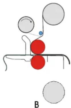
chemical
Diagram of a molecular interaction or binding process with red spheres and gray surrounding circles, labeled Bnatural_image
Diagram of a mechanical or fluid system with red and gray spheres connected by rods, no text or symbols presentA

natural_image
Diagram of a mechanical or biological process with red and gray spheres connected by rods, no visible text or symbolsB
natural_image
Diagram of a mechanical or biological structure with red and gray spheres connected by lines, labeled 'A' at bottom (no text or symbols within diagram)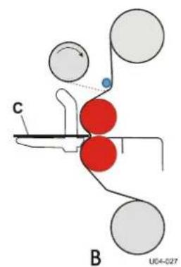
chemical
Molecular interaction diagram showing red and gray spheres representing different atoms, with labeled components C and BNote: We recommend that you make a photocopy of this page. With each successfully run application, record the process and settings and a diagram of the webbing procedure. Keep the record so the application can be repeated at a later date.

If a standard image is made available for each new process then sales materials and sales can be developed for reference.
LAMINATOR SETTINGS
Media:
Process:
Application Use:
Upper Unwind Shaft:
Lower Unwind Shaft:
Wind-up Tube:
Motor Speed Setting:
WEBBING SETTINGS
Web Tension Upper Unwind Shaft:
Light / Med. / Heavy
Web Tension Lower Unwind Shaft:
Light / Med. / Heavy
Nip Height:
flowchart
graph TD
    A["In-feed Table"] --> B["Top Main Roller"]
    A --> C["Bottom Main Roller"]
    D["Wind-up Tube"] --> E["Output Table"]
    F["Upper Unwind Shaft"] --> G["Lower Unwind Shaft"]
    H["Image Guide"] --> I["Top Main Roller"]
Figure 25: Blank Webbing Diagram
9 GLOSSAR
Aufziehen
text_image
S S L L S U04-030Nota:
text_image
Diagram of a control panel with labeled buttons and rotary indicators, numbered 1 to 9.Figura 8
natural_image
Close-up of a white industrial machine with a red and black knob, showing a roller and mechanical components (no text or symbols visible)Figura 11: Leva de bloqueo subida
natural_image
Close-up of a white industrial machine with a red and black knob and yellow button (no visible text or symbols)natural_image
Close-up of a white industrial control unit with mechanical components and a red warning label (no readable text or symbols beyond safety warnings)natural_image
Diagram of a mechanical or fluidic system with red and gray spheres connected by rods, no text or symbols present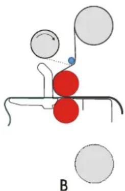
natural_image
Diagram of a molecular interaction with red spheres and gray spheres, no text or symbols presentnatural_image
Diagram of a mechanical or fluidic system with red and gray spheres, connected by curved lines and a blue dot, labeled 'A' at bottom (no text or symbols on diagram itself)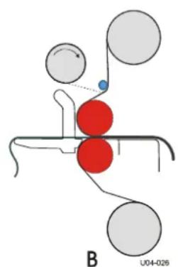
chemical
Molecular interaction diagram showing red and gray spheres representing different atoms or functional groups, with a blue dot indicating a specific site.natural_image
Diagram of a mechanical or biological structure with red and gray spheres, no visible text or symbols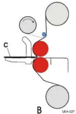
chemical
Molecular interaction diagram showing red and gray spheres representing different atoms, with labeled components C and BNote: We recommend that you make a photocopy of this page. With each successfully run application, record the process and settings and a diagram of the webbing procedure. Keep the record so the application can be repeated at a later date.

If a standard image is made available for each new process then sales materials and sales can be developed for reference.
LAMINATOR SETTINGS
Media:
Process:
Application Use:
Upper Unwind Shaft:
Lower Unwind Shaft:
Wind-up Tube:
Motor Speed Setting:
WEBBING SETTINGS
Web Tension Upper Unwind Shaft:
Light / Med. / Heavy
Web Tension Lower Unwind Shaft:
Light / Med. / Heavy
Nip Height:
flowchart
graph TD
    A["In-feed Table"] --> B["Top Main Roller"]
    B --> C["Bottom Main Roller"]
    C --> D["Output Table"]
    E["Wind-up Tube"] --> F["Upper Unwind Shaft"]
    G["Image Guide"] --> H["Top Main Roller"]
Figure 25: Blank Webbing Diagram
9 GLOSARIO DE TÉRMINOS
Encolado previo
text_image
S S L L S U04-030Nota:
text_image
Diagram of a control panel with labeled buttons and rotary indicators, numbered 1 to 9.Figura 8
natural_image
Close-up of a white industrial machine with a red and yellow button, showing a rolled paper or scroll (no visible text or symbols)natural_image
Close-up of a white industrial machine with a red and black knob and yellow button (no visible text or symbols)natural_image
Diagram of a mechanical or biological process with red and gray spheres, no visible text or symbols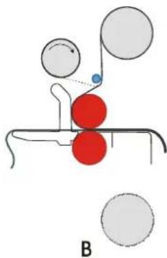
natural_image
Diagram of a molecular interaction or mechanical process with red spheres and gray spheres, no text or symbols presentnatural_image
Diagram of a mechanical or fluidic system with red and gray spheres connected by rods, labeled 'A' at bottom (no text or symbols on diagram itself)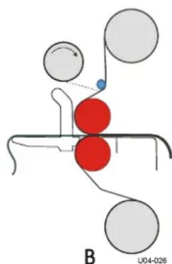
chemical
Molecular interaction diagram showing red and gray spheres representing different atoms or functional groups, with labeled point B and identifier U04-026flowchart
graph TD
    A["1"] --> B["2"]
    B --> C["3"]
    C --> A
Note: We recommend that you make a photocopy of this page. With each successfully run application, record the process and settings and a diagram of the webbing procedure. Keep the record so the application can be repeated at a later date.

If a standard image is made available for each new process then sales materials and sales can be developed for reference.
LAMINATOR SETTINGS
Media:
Process:
Application Use:
Upper Unwind Shaft:
Lower Unwind Shaft:
Wind-up Tube:
Motor Speed Setting:
WEBBING SETTINGS
Web Tension Upper Unwind Shaft:
Light / Med. / Heavy
Web Tension Lower Unwind Shaft:
Light / Med. / Heavy
Nip Height:
flowchart
graph TD
    A["In-feed Table"] --> B["Top Main Roller"]
    B --> C["Bottom Main Roller"]
    C --> D["Output Table"]
    E["Wind-up Tube"] --> F["Upper Unwind Shaft"]
    G["Image Guide"] --> H["Top Main Roller"]
Figure 25: Blank Webbing Diagram
9 GLOSSARIO
SEAL Brands Technical Service – US & Canada
Ph: 1-800-486-6502
Fax: 1-800-966-4554
Email: tsorder@acco.com
SEAL Brands Customer Service – US & Canada
Ph: 1-800-257-7325
Fax: 1-800-966-4554
Email: csorder@acco.com

www.sealgraphics.com

BRANDS
ACCO BRANDS
Four Corporate Drive
Lake Zurich, IL 60047-8997
accobrands.com