
JJN 50 - Guitar amp BLACKSTAR - Free user manual and instructions
Find the device manual for free JJN 50 BLACKSTAR in PDF.

User questions about JJN 50 BLACKSTAR
0 question about this device. Answer the ones you know or ask your own.
Ask a new question about this device
Download the instructions for your Guitar amp in PDF format for free! Find your manual JJN 50 - BLACKSTAR and take your electronic device back in hand. On this page are published all the documents necessary for the use of your device. JJN 50 by BLACKSTAR.
USER MANUAL JJN 50 BLACKSTAR
Blackstar Amplification Ltd, Beckett House, 14 Billing Road, Northampton, NN1 5AW, UK For the latest information go to: www.blackstaramps.com
Whilst the information contained herein is correct at the time of publication, due to our policy of constant improvement and development. Blackstar Amplification Ltd reserves the right to alter specifications without prior notice.
263401M-VA-A 06/24
Blackstar®
AMPLIFICATION
the sound in your head
JJN 50
Owner's Manual
[Non-Text]


Designed & Engineered by Blackstar Amplification UK
IMPORTANT SAFETY INSTRUCTIONS
- Read these instructions.
- Keep these instructions.
- Heed all warnings.
- Follow all instructions.
- Do not use this apparatus near water.
- Clean only with a dry cloth.
- Do not block any ventilation openings.
- Install in accordance with the manufacturer's instructions.
- Do not install near any heat sources such as radiators, heat registers, stoves, or other apparatus (including amplifiers) that produce heat.
- Do not defeat the safety purpose of the polarized or grounding type plug. A polarized plug has two blades with one wider than the other. A grounding type plug has two blades and a third grounding prong. The wide blade or the third prong are provided for your safety. If the provided plug does not lift into your outlet, consult an electrician for replacement of the obsolete outlet.
- Protect the power cord from being walked on or pinched particularly at plugs, convenience receptacles, and the point where they exit from the apparatus.
- Only use attachments/accessories specified by the manufacturer.
- Unplug this apparatus during lightning storms or when unused for long periods of time.
- Refer all servicing to qualified service personnel. Servicing is required when the apparatus has been damaged in any way, such as power-supply cord or plug is damaged, liquid has been spilled or objects have fallen into the apparatus, the apparatus has been exposed to rain or moisture, does not operate normally, or has been dropped.
"TO COMPLETELY DISCONNECT THIS APPARATUS FROM THE AC MAINS, DISCONNECT THE POWER SUPPLY CORD PLUG FROM THE AC RECEPTACLE".
"WARNING: TO REDUCE THE RISK OF FIRE OR ELECTRIC SHOCK, DO NOT EXPOSE THIS APPARATUS TO RAIN OR MOISTURE AND OBJECTS FILLED WITH LIQUIDS, SUCH AS VASES, SHOULD NOT BE PLACED ON THIS APPARATUS".

This symbol is intended to alert the user to the presence of important operation and maintenance (servicing) instructions in the literature accompanying the appliance.

This symbol is intended to alert the user to the presence of uninsulated "dangerous voltage" within the product's enclosure that may be of sufficient magnitude to constitute a risk of electric shock to persons.

BLACK ★
BLACK ★
Warning!
Important safety information!
READ THE FOLLOWING INFORMATION CAREFULLY. SAVE ALL INSTRUCTIONS FOR FUTURE REFERENCE!
Follow all warnings and instructions marked on the product! Danger! High internal operating voltages.
Do not open the equipment case. There are no user serviceable parts in this equipment. Refer all servicing to qualified service personnel.
Clean only with a dry cloth.
Condensation can form on the inside of an amplifier if it is moved from a cold environment to a warmer location. Before switching the unit on, it is recommended that the unit be allowed to reach room temperature.
Unauthorised modification of this equipment is expressly forbidden by Blackstar Amplification Ltd.
Never push objects of any kind into ventilation slots on the equipment casing.
Do not expose this apparatus to rain, liquids or moisture of any type.
Avoid placing vessels filled with liquid on top of the amplifier.
Do not place this product on an unstable trolley, stand or table. The product may fall, causing serious damage to the product or to persons!
Do not cover or block ventilation slots or openings.
This product should not be placed near a source of heat such as a stove, radiator, or another heat producing amplifier.
Use only the supplied power cord which is compatible with the mains voltage supply in your area.
Power supply cords should always be handled carefully and should be replaced if damaged in any way.
Never break off the earth (ground) pin on the power supply cord.
The power supply cord should be unplugged when the unit is to be unused for long periods of time.
Before the unit is switched on, the loudspeaker should be connected as described in the handbook using the lead recommended by the manufacturer.
Always replace damaged fuses with the correct rating and type.
Never disconnect the protective mains earth connection.
High loudspeaker levels can cause permanent hearing damage. You should therefore avoid the direct vicinity of loudspeakers operating at high levels. Wear hearing protection if continuously exposed to high levels.
If the product does not operate normally when the operating instructions are followed, then refer the product to a qualified service engineer.
Only suitable for safe use under non-tropical climate conditions.
Maximum ambient temperature for operation: 35^ C
Always make sure that the power cable is connected to a socket/outlet with an earthed connection.
Mains Voltage: 100-240V\~ 50/60Hz
This amplifier is only designed and evaluated for safety at a maximum altitude of 2000m.

The U.S. Government's Occupational Safety and Health Administration (OSHA) has specified the following permissible noise level exposures:
Duration Per Day In Hours Sound Level dBA, Slow Response
| 8 | 90 | |
| 6 | 92 | |
| 4 | 95 | |
| 3 | 97 | |
| 2 | 100 | |
| 112 | 102 | |
| 1 | 105 | |
| 12 | 110 | |
| 14 or less | 115 |
According to OSHA, any exposure in excess of the above permissible limits could result in some hearing loss.
Ear plug protectors in the ear canals or over the ears must be worn when operating this amplification system in order to prevent a permanent hearing loss if exposure is in excess of the limits as set forth above. To ensure against potentially dangerous exposure to high sound pressure levels, it is recommended that all persons exposed to equipment capable of producing high sound pressure levels such as this amplification system be protected by hearing protectors while this unit is in operation.

All electrical and electronic products should be disposed of separately from the municipal waste stream via designated collection facilities appointed by the government or the local authorities.


A message from Jared...
"I first plugged in to a Blackstar amp in 2010. I remember the feeling it gave me, I LOVED IT. When I first chased my dream of forming my band and making original music, it started with a Los Paul and a Blackstar. Now 14 years later, that combination remains the same. Simply put, I have developed and found my entire sonic sound with Blackstar."
In 2019, I was blessed to release my first signature model, the JIN 20. I couldn't have been more happy. But as time went on and my career continued to grow, so did my needs in an amplifier. So here we are...The JIN 50, an absolute beast of an amp. Packing all of the power, tone, versatility, and inspiration I could ever ask for, this one can genuinely do it all. I proudly worked closely with the engineers on every single facet of this amp, we put our heart and soul into it. I am absolutely blown away by the final product and I think you will be too.
I hope you harness the musical freedom and passion in this amplifier. Although it is a signature model, rest assured, it was designed with the intention to speak to you, empower you, and inspire YOU on your musical journey.
Much love & BLUES POWER!"
Jared James Nichols

Introduction
Thank you for purchasing this Blackstar JUN 50 amplifier. Like all our products, this amp is the result of countless hours of painstaking Research and Development by our world-class design team. Based in Northampton (United Kingdom), the Blackstar team are all experienced musicians themselves and the sole aim of the development process is to provide guitarists with products which are the ultimate tools for self-expression.
All Blackstar products are subjected to extensive laboratory and road testing to ensure that they are truly uncompromising in terms of reliability, quality and above all TONE.
The JNJ 50 amplifier has been designed with Jared to harness all the grit, snarl and bite that makes vintage valve amps so sought after and is an evolution of sonic design from Jared's first signature with us, the JJN-20. Although at first glance the JJN 50 looks to be reassuringly simple, it actually contains advanced features and cutting-edge technology to provide guitarists with tools they can use in many different playing scenarios; from stage to studio, home practice / recording and silent 'orchestra pit' use. All while still being a true valve amp. They are an inspired combination of the best that analogue audio circuitry and digital signal processing can provide.
Although you may be tempted to plug straight in and play (and are welcome to), please at some point read through this handbook carefully, to ensure you get the maximum benefit from your new Blackstar product and all the available features. (It will only take about 20 minutes, honest!)
The JUN 50 shares the same design innovations as St. James to make it incredibly light. One of the goals when developing St. James was to produce real valve amps at lighter weights than were previously dreamed of. In doing this, we looked at all the different areas where weight could be saved, that would not compromise the sound, performance or reliability. This involved using new and cutting-edge technology, along with specifically chosen materials, in the design and construction of the power supply, the speakers, the output transformer, chassis metalwork and cabinet woodwork. Increment by increment we minimised weight throughout the design.
If you like what you hear and want to find out more about the Blackstar range of products, please visit our website at www.blackstaramps.com.
Thanks!
The Blackstar Team
Features
The JJN 50 is a highly versatile amplifier suited to a wide range of playing styles and situations.
Channel I: The valve gain structure and voicing of this channel has been inspired by classic American amplifiers of the mid '60s. It is very clean and bright, but with a solid low-end and controlled mids. Also, on this channel the valve power stage is set to be tight, relatively clean and linear across the frequency range.
This is one of the most popular choices for a 'pedal platform' as it provides a solid clean foundation to apply effects to.
Channel II: This channel has a 'classic' valve preamp topology which is based on a much-loved British 'Class A' amplifier of the early '60s. This is a low to medium gain preamp that can be used clean, warm or mildly overdriven. Again, this is a very popular choice for a 'pedal platform' as well as for a great responsive crunch tone. When this channel is selected the valve power stage is set as 'open loop'. This has a looser feel with a resonant bottom-end and lively highs.
The footswitchable BLUES POWER setting pushes the valve proamp harder with a 10dB clean boost, to take it from 'chimey' to 'creamy' and beyond.
The JJN 50 also features a 3 way Power switch to give the user options on how their valve output stage is run.
On the rear panel, in addition to the expected effects loop and footswitch sockets, we have also included separate stereo headphone, balanced XLR and USB outputs.
Key to the great sound from these is two very important additions. First is the inclusion of an internal reactive load, specially designed to load the valve output stage in the same way as a guitar speaker. The other is our newly developed CabRig DSP technology to provide the user cutting-edge cabinet, speaker and room simulation. This opening overview cannot do it justice, therefore CabRig will have documentation all of its own
Front Panel
1. Input
Plug your guitar in here. Always use a good quality screened guitar lead.
With no jack applied to the input the amplifier will automatically be switched to a safe, low power consumption, silent mode.
2. Volume I
This controls the volume of Channel I. Turning it clockwise increases the volume. At extreme clockwise settings the preamplifier will start to overdrive slightly. It has a natural, variable 'bright' response designed in. At lower settings the tone is 'brighter' with comparatively more high frequencies passed though. As the control is increased the perceived brightness is effectively reduced due to the increase in all other frequencies.
3. CH. II Select
This switch selects between the two preamp channels, as well as adjusting the response of the valve power amp. With the LED off it is set to Channel I which is the cleaner, 'mid '60s American' preamp and a tight, linear response from the power amp. Switching to CH. II will turn the LED on and activate Channel II.
Channel II on the JJN 50 uses an early '60s British style valve preamp gain structure and sets the power amp to be loose and resonant.
When the footswitch is connected this switch is bypassed but the LED will still indicate the channel status.
4. Gain II
This controls the gain of Channel II and the amount of overdrive or distortion. Lower settings will clean up and respond well to the player's dynamics and guitar volume setting. Higher Gain II settings will push the valves harder into progressively more overdrive and distortion.
5. BLUES POWER Switch
This switch selects between the two voices of Channel II.
With BLUES POWER on, a clean 10dB boost is added at the input stage which pushes the valve preamp into overdrive, although the basic tonality remains recognisable.
The power stage remains 'open loop' in both settings, therefore loose and resonant.
When the footswitch is connected this switch is bypassed, but the LED will still indicate the BLUES POWER status.
6. Volume II
This control adjusts the overall volume of Channel II. Turning it clockwise increases the volume. This is useful for setting the required balance between the two channels.
7. Bass
This adjusts the amount of low-end frequencies in your tone. High settings will be fat, warm and resonant. Low settings will be thinner, but sometimes less muddy. This is a dual 'potentiometer' with each part working separately and differently on each channel. More on this below.
8. Middle
This adjusts the amount of mid frequencies in your tone. The middle frequencies are particularly important in setting the amount of 'body' 'your tone has. As with the Bass control, this is a dual 'potentiometer' with each part working separately and differently on each channel. More on this below.
9. Treble
This adjusts the amount of high frequencies in your tone. At low settings the sound will be warm and darker in character. As it is increased the sound will become brighter, eventually to the point of being aggressive and cutting. Again, this is a dual 'potentiometer' with each part working separately and differently on each channel. More on this below.
Differences in EQ 'tone stacks' on each channel:
At Blackstar we are always trying to get the best versions of a specific tone and spend hours (days!) analysing circuits; both electronically and sonically. We felt that despite having one set of EQ controls, a 'one size fits all' approach for all the channels was not good enough. Therefore, we have used dual pots for each of the Bass, Middle and Treble controls and kept the rest of the EQ components electrically independent. This means we did not need to compromise on the control frequencies and level ranges of any of them. Instead, we have tuned the EQ to be different for each channel type and have used what is most appropriate for the specific channel.
Channel I uses the same EQ topology as expected for a mid '60s American clean tone. Bright treble, restrained middle and solid bass.
Channel II uses a highly interactive Bass and Treble arrangement, appropriate for the 'chirney' clean and crunch tones it produces.
For the MIDDLE control we have configured it as an active mid cut and boost. In the middle / centre position it is not altering the tone at all, but turning up or down allows a very useful way to shape the mid-range without affecting the expected operation of the classic Bass and Treble circuit.
10. Reverb
The REVERB control sets the overall level of the reverb effect. With the control at minimum there will be no reverb. Turning it clockwise will increase the amount of reverb.
11. Power Switch
This 3-way miniature toggle switch allows the user to switch between three very different power output settings:
50W - This is the full power setting which will give the loudest clean headroom. This is likely to be used for live, stage use.
SAG - This includes a power supply 'sag' which is a form of dynamic compression that will be most noticeable on loud transients (attack). The overall headroom will be lower than the 50W setting and the 'feel' will be softer and more 'vintage'. Needs to be experienced to understand.
2W - This is the low power setting and as suggested reduces the output power way down to a maximum of 2 watts. This is likely to be used when practising, recording and at smaller gigs, or when a more overdriven power amp tone is desired.

12. Master
This controls the overall volume of the amplifier through all the following outputs:
■ SPEAKER OUTPUTS (also dependent on the Power switch setting (11).
■ D.I. OUTPUT XLR
■ LINE OUT / PHONES Jack
■ USB AUDIO output
Minimum will be no signal, fully clockwise will be the loudest. (You knew that, right?)
13. STBY Switch
This large toggle Standby switch selects between two different modes:
Position '0' disconnects the main Speaker Outputs therefore there will be no sound from any connected speaker. It also re-routes the output of the valve power amp signal to the internal reactive load. This is intended for silent recording use from any of the CabRig speaker simulated outputs. The guitar signal will still be passing through the whole amp from Input to after the power amp, through the internal reactive load and CabRig. Therefore, the tone remains intact. As the Speaker Outputs themselves are disconnected in this mode then the unit can be used without being connected to an external speaker load without worry of damage.
In certain settings there may be a faintly audible amount of 'bleed-through' of signal to the speaker(s). If this needs to be eliminated completely then it is okay to disconnect the speaker lead from the rear panel. (Refer to Rear Panel section 4 for more information.)
Position 'I' will connect the Speaker Outputs, therefore driving the speakers as normal, and disconnecting the internal reactive load. The signal sent to the CaoRig DSP will be from the same point, only now it will be loaded by the external speaker rather than the internal reactive load.
All the CabRig Outputs can be used in either position as required or preferred.
14. Power Switch
This large toggle switch is used to turn the whole amplifier on and off.
Position '0' is completely off, the same as detaching the mains cable.
Position 'I' is on. Actual functionality will be dependent on other settings, including STBY and the small Power toggle switch, as well as what is connected to Input and Speaker Outputs.
When switched on, the front 'BLACKSTAR' logo will light up and inform the band and audience members of your impeccable taste in choosing this product.
Rear Panel
1. Mains Fuse
The value of the mains fuse is specified on the rear panel. Never use a fuse of the incorrect value or attempt to bypass it.

2. Mains Input
The supplied detachable mains lead is connected here.
Unusually for valve amplifiers, the JJN 50 is designed with a universal input power supply. This means that the mains input range is rated at 100Vac to 240Vac and capable of operating at 50Hz and 60Hz. (We actually test them beyond these rated limits.)
Therefore, these products can be used anywhere in the world without needing to adjust anything. Not only will they simply function wherever used, but they will also be completely consistent in tone and output power, regardless of any changes or fluctuations in local mains supply. Along with the size and weight benefits, this makes them ideal for a musician who travels internationally.
3. H.T. Fuse
The value of the H.T. fuse is specified on the rear panel. Never use a fuse of the incorrect value or attempt to bypass it.
4. Speaker Outputs
The output marked '1 x 16 OHM' is for the connection of a single 16 Ohm extension speaker cabinet or the internal speaker(s).
The outputs marked '1 x 8 OHM OR 2 x 16 OHM' are for the connection of either a single 8 Ohm extension cabinet or two 16 Ohm cabinets.
'1x16 Ohm' output '1x8 Ohm or 2x16 Ohm' outputs
| Internal 16 Ohm combo speaker(s) √ | X | X | ||
| Internal 16 Ohm combo speaker(s) plus one 16 Ohm extension cab | X | √ | √ | |
| One 16 Ohm extension cabinet √ | X | X | ||
| Two 16 Ohm extension cabinets | X | √ | √ | |
| Single 8 Ohm extension cabinet | X | √ | X |
WARNING: The output marked '1x16 Ohm' should never be used at the same time as any of the outputs marked '1x8 Ohm or 2x16 Ohm'. Failure to correctly match the impedance of the amplifier and speakers will damage the amplifier.
NOTE: Unlike many other valve amps, those have clover sensing and switching which means that they can be used without being connected to a speaker load.
If the speaker lead is disconnected at the amplifier end then it will automatically switch it to a safe, low power consumption mode.
When using the STBY 0 mode then the output is automatically switched to the internal reactive load, meaning the speaker connection is disconnected anyway.
Therefore, for example, if you wish to record using the head and take the output from either the XLR, stereo jack, or USB, then you can set it on your desk without any need to be connected to a speaker load.
IMPORTANT NOTE: The protection sensing is at the speaker output jacks on the unit. So, do not disconnect at the speaker end only. Disconnect at the amp!

5. CabRig Speaker Simulated Output - Mono Balanced XLR D.I. Output socket
This output is for using an Industry standard 3 pin XLR cable for connection to a recording device, stage box or mixing desk. This provides a low noise, low impedance, quality connection for recording or live use.
The signal will be the actual speaker output signal (including power valves and output transformer), that has then been passed through the CabRig technology, to apply the authentic feel and response of a 'mic'd up guitar speaker cabinet in a room'. The actual sound is dependent on the CabRig switch setting and the more in depth settings within the CabRig software.
More on this in the separate CabRig documentation.
As it is derived from post-power amp then the Master control will affect the signal level sent from this socket.
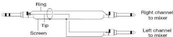
6. CabRig Speaker Simulated Output - Stereo Jack Line Out / Phones Socket
This 1/4" TRS jack socket provides a stereo connection to connect to a recording device or mixing desk. Always use a good quality TRS (stereo) type lead or TRS to 2 x TS (mono) (see diagram below).
It can also connect to headphones therefore allowing silent practice with the STBY switch set to '0'.
Again, the signal will be derived from the actual speaker output via the CabRig technology, providing a high-quality authentic 'mic'd cab' response. The actual sound is dependent on the CabRig switch setting and the more in-depth settings within the CabRig software app.
More on this in the separate CabRig documentation.
The signal level from this output will also be controlled by the MASTER control.
When using headphones, please take into consideration that loud sounds over extended periods can result in hearing damage, both short term, long term and permanent. We spend a long time making our amps sound good, so we'd prefer that you have a long life of good hearing to be able to enjoy them.
7. CabRig Switch
This allows the user to switch between the three currently stored CabRig settings. Almost unlimited further options and permutations are controlled and set in the CabRig software.
More on this in the separate CabRig documentation.
8. Effects Loop Return Socket
Connect the (mono) output of an external effects unit here.

9. Effects Loop Send Socket
Connect the (mono) input of an external effects unit here.
10. Effects Loop Level Switch
The Level switch sets the effects loop to either +4dBu or -10dBV, which enables the user to use it with either professional audio equipment (+4dBu) or with guitar level effects such as effects pedals (-10dBV). If unsure, use -10dBV to start with.
11. Footswitch
The supplied 2-way footswitch can be connected here. The footswitch will enable the selection between Channel I and Channel II and also select between BLUES POWER setting of Channel II.
NOTE: Using this socket will disable the front panel Channel and BLUES POWER switch. Therefore, full control via the footswitch is granted irrespective of how the amplifier is set. When using the supplied footswitch, the Channel and Voice LEDs on the amplifier will always display the current setting. On the footswitch, if BLUES POWER is selected for CH. II then this LED will remain it even when on CH. I, to let the user know the CH. II settings before they go to it. This prevents any surprise of difference in gain or volume when switching channels.
EXTERNAL SWITCHING: This socket can also be used by people who wish to control the channel and voice / boost switching using an external switching device that connects via a common TRS jack to jack connection.
The following external conditions will switch the Channels and Voices / Boost as follows:
TIP RING CHANNEL BLUES POWER
| Closed Closed Channel | N/A |
Closed Open Channel I N/A
| Open Closed Channel II OFF |
Open Open Channel II ON
12. USB Audio socket
This B-type USB socket is for the connection to a computer via a suitable lead (not supplied).
This is for USB digital audio output and for connecting to the CabRig software. Again, the signal for the digital audio will be derived from the actual speaker output via the CabRig technology; providing a high-quality authentic mic'd cab response. The actual sound is dependent on the CabRig switch setting and the more in-depth settings within the CabRig software.
More on this in the separate CabRig documentation.
For a guide on low latency USB recording visit: www.blackstaramps.com/usbrecording
NOTE: Always connect the amplifier via a main USB port; often found on the rear of the computer or side of the laptop. The amplifier will appear as an audio capture device within recording software.
Technical Specification
JJN 50 Head
Power (RMS): 50 Watts
Valves: 2 x ECG83, 2 x EL34
Weight (kg): 7.7
Dimensions (mm): 495 (W) × 241(H) × 228(D)
Footswitch: FS-19 included
Warnung!
7. Schalter CabRig
7. Sélecteur CabRig
All electrical and electronic products should be disposed of separately from the municipal waste stream via designated collection facilities appointed by the government or the local authorities.

BLACK ★
4342 4
Introducción
1. Fusible Principal
7. CAB RIG スイッチ
| TIP | RING | CHANNEL | BLUES POWER |
| Closed | Closed | CHANNEL I | N/A |
| Closed | Open | CHANNEL I | N/A |
| Open | Closed | CHANNEL II | OFF |
| Open | Open | CHANNEL II | ON |
BLACK ★
12. USB AUDIO ソケット
At electrical and electronic products should be disposed of separately from the municipal waste stream via designated collection facilities appointed by the government or the local authorities.

介绍
7. CabRig开关


- Blackstar®
- IMPORTANT SAFETY INSTRUCTIONS
- Warning!
- A message from Jared...
- Introduction
- Features
- Front Panel
- Input
- Volume I
- CH. II Select
- Gain II
- BLUES POWER Switch
- Volume II
- Bass
- Middle
- Treble
- Differences in EQ 'tone stacks' on each channel:
- Reverb
- Power Switch
- Master
- STBY Switch
- Power Switch
- Rear Panel
- Mains Fuse
- Mains Input
- H.T. Fuse
- Speaker Outputs
- CabRig Speaker Simulated Output - Mono Balanced XLR D.I. Output socket
- CabRig Speaker Simulated Output - Stereo Jack Line Out / Phones Socket
- CabRig Switch
- Effects Loop Return Socket
- Effects Loop Send Socket
- Effects Loop Level Switch
- Footswitch
- USB Audio socket
- Technical Specification
- JJN 50 Head
- Warnung!
- Schalter CabRig
- Sélecteur CabRig
- Introducción
- Fusible Principal
- CAB RIG スイッチ
- USB AUDIO ソケット
- 介绍
- CabRig开关
Brand : BLACKSTAR
Model : JJN 50
Category : Guitar amp