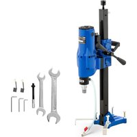
DDM300 - Drill MSW - Free user manual and instructions
Find the device manual for free DDM300 MSW in PDF.


| Product type | Core drill (diamond core drill) |
| Brand | MSW |
| Model | DDM300 |
| Rated voltage | 230 V ~ 50 Hz |
| Rated power | 2800 W |
| Rated current | 12 A |
| Rotation speed (no load) | 920 min⁻¹ (high speed) / 500 min⁻¹ (low speed) |
| Maximum drilling diameter | 300 mm |
| Drilling stroke | 465 mm |
| Water connection diameter | 16 mm |
| Maximum permitted water pressure | 0.12 MPa |
| Dimensions (L × W × H) | 390 × 375 × 903 mm |
| Net weight | 30.2 kg |
| Sound power level (LWA) | 110.4 dB(A) (K=3 dB) |
| Sound pressure level (LpA) | 97.4 dB(A) (K=3 dB) |
| Required personal protective equipment | Safety glasses, noise-cancelling headset, mask, safety shoes, gloves, face protection |
| Main functions | Water drilling in concrete, asphalt, stone; electronic speed control (2 speeds) |
| Maintenance and cleaning | Unplug before cleaning; use damp cloth without solvents; clean ventilation openings |
| Safety | Automatic stop in case of overload; water protection; on/off switch |
| Spare parts and repairability | Replaceable carbon brushes; repairs by after-sales service only |
| General information | Compliant with European standards; do not dispose with household waste |
Frequently Asked Questions - DDM300 MSW
User questions about DDM300 MSW
0 question about this device. Answer the ones you know or ask your own.
Ask a new question about this device
Download the instructions for your Drill in PDF format for free! Find your manual DDM300 - MSW and take your electronic device back in hand. On this page are published all the documents necessary for the use of your device. DDM300 by MSW.
USER MANUAL DDM300 MSW
Modell MSW-DDM205P24
Modell MSW-DDM255G2B
natural_image
Close-up of a red industrial robotic arm with a circular inset showing a close-up of the mechanical component (no visible text or symbols)The user manual is designed to assist in the safe and trouble-free use of the device. The product is designed and manufactured in accordance with strict technical guidelines, using state-of-the-art technologies and components. Additionally, it is produced in compliance with the most stringent quality standards.
DO NOT USE THE DEVICE UNLESS YOU HAVE THOROUGHLY READ AND UNDERSTOOD THIS USER MANUAL.
To increase the product life of the device and to ensure trouble-free operation, use it in accordance with this user manual and regularly perform maintenance tasks. The technical data and specifications in this user manual are up to date. The manufacturer reserves the right to make changes associated with quality improvement. The device is designed to reduce noise emission risks to a minimum, taking into account technological progress and noise reduction opportunities.
LEGEND
| CE | The operation manual must be read carefully. |
| Never dispose of electrical equipment together with household waste. | |
| This machine conforms to CE declarations. | |
| WARNING! or CAUTION! or REMEMBER! Applicable to the given situation (general warning sign). | |
| Safety goggles must be used. | |
| Ear protection must be used. | |
| Safety mask must be used. | |
| Protective footwear must be used. | |
| Attention! Wear protective gloves. | |
| Wear a face shield. | |
| ATTENTION! Electric shock warning! |
PLEASE NOTE! Drawings in this manual are for illustration purposes only and in some details may differ from the actual machine.
The original operation manual is in German. Other language versions are translations from German.
2. USAGE SAFETY
ATTENTION! Read all safety warnings and all instructions. Failure to follow the warnings and instructions may result in an electric shock, fire and/or serious injury or even death.
The terms "device" or "product" are used in the warnings and instructions to refer to DIAMOND DRILLING MACHINE.
2.1. ELECTRICAL SAFETY
c) Do not touch the device with wet or damp hands.
a) The plug must fit the socket. Do not modify the plug in any way. Using original plugs and matching sockets reduces the risk of electric shock.
b) Avoid touching earthed elements such as pipes, heaters, boilers and refrigerators. There is an increased risk of electric shock if the earthed device is exposed to rain, comes into direct contact with a wet surface or is operating in a damp environment. Water getting into the device increases the risk of damage to the device and of electric shock.
d) Use the cable only for its designated use. Never use it to carry the device or to pull the plug out of a socket. Keep the cable away from heat sources, oil, sharp edges or moving parts. Damaged or tangled cables increase the risk of electric shock.
e) If working with the device outdoors, make sure to use an extension cord suitable for outdoor use. Using an extension cord suitable for outdoor use reduces the risk of electric shock.
f) If using the device in a clamp environment cannot be avoided, a residual current device (RCD) should be applied. The use of an RCD reduces the risk of electric shock.
g) Do not use the device if the power cord is damaged or shows obvious signs of wear. A damaged power cord should be replaced by a qualified electrician or the manufacturer's service centre.
h) To avoid electric shock, do not immerse the cord, plug or device in water or other liquids. Do not use the device on wet surfaces.
i) ATTENTION! DANGER TO LIFE! While cleaning, never immerse the device in water or other liquids.
j) Do not use in very humid environments or in the direct vicinity of water tanks.
k) Prevent the device from getting wet. Risk of electric shock!
1) The supply voltage must not differ from the rated voltage by more than +/- 5%.
2.2. SAFETY IN THE WORKPLACE
a) Make sure the workplace is clean and well lit. A messy or poorly lit workplace may lead to accidents. Try to think ahead, observe what is going on and use common sense when working with the device.
b) Do not use the device in a potentially explosive environment, for example in the presence of flammable liquids, gases or dust.
c) If you discover damage or irregular operation, immediately switch the device off and report it to a supervisor without delay.
d) If there are any doubts as to the correct operation of the device, contact the manufacturer's support service.
e) Only the manufacturer's service point may repair the device. Do not attempt any repairs independently!
f) In case of fire, use a powder or carbon dioxide (CO₂) fire extinguisher (one intended for use on live electrical devices) to put it out.
g) Children or unauthorised persons are forbidden to enter a work station. (A distraction may result in loss of control over the device)
h) Use the device in a well-ventilated space.
i) The device produces dust and debris during operation. It is important to protect bystanders from their harmful effects.
j; Regularly inspect the condition of the safety labels. If
the labels are illegible, they must be replaced.
k) Please keep this manual available for future reference. If this device is passed on to a third party, the manual must be passed on with it.
1) Keep packaging elements and small assembly parts in a place not available to children.
m) Keep the device away from children and animals.
n) If this device is used together with another equipment, the remaining instructions for use shall also be followed.
Consider the work area environment before starting to work. Don't expose power tools to rain or wet soil. Don't use power tools in damp or wet locations. The work area should be well secured. Don't use the tool in the presence of flammable liquids or gases. Power tools produce sparks during normal operation or when switching ON/OFF. Never use power tools in dangerous sites containing lacquer, paint, benzene, thinner, gasoline, gases, adhesive agents, and other materials which are combustible or explosive.
REMEMBER! When using the device, protect children and other bystanders.
2.3. PERSONAL SAFETY
a) Do not use the device when tired, ill or under the influence of alcohol, narcotics or medication which can significantly impair the ability to operate the device.
b) The machine may be operated by physically fit persons who are able to handle the machine, are properly trained, who have reviewed this operating manual and have received training in occupational health and safety.
c) When working with the device, use common sense and stay alert. Temporary loss of concentration while using the device may lead to serious injuries.
d) Use personal protective equipment as required for working with the device, specified in section 1 (Legend). The use of correct and approved personal protective equipment reduces the risk of injury.
e) To prevent the device from accidentally switching on, make sure the switch is on the OFF position before connecting to a power source
f) Do not overestimate your abilities. When using the device, keep your balance and remain stable at all times. This will ensure better control over the device in unexpected situations.
g) Do not wear loose clothing or jewellery. Keep hair, clothes and gloves away from moving parts. Loose clothing, jewellery or long hair may get caught in moving parts.
h) Use eye, ear and respiratory protection.
The device is not a toy. Children must be supervised to ensure that they do not play with the device.
2.4.SAFE DEVICE USE
a) Do not overload the device. Use the appropriate tools for the given task. A correctly-selected device will perform the task for which it was designed better and in a safer manner.
b) Do not use the device if the ON/OFF switch does not function properly (does not switch the device on and off). Devices which cannot be switched on and off using the ON/OFF switch are hazardous, should not be operated and must be repaired.
c) Make sure the plug is disconnected from the socket before attempting any adjustments, accessory replacements or before putting the device aside. Such precautions will reduce the risk of accidentally activating the device.
d) When not in use, store in a safe place, away from children and people not familiar with the device who have not read the user manual. The device may pose a hazard in the hands of inexperienced users.
c) Keep the device in perfect technical condition. Before each use check for general damage and especially check for cracked parts or elements and for any other conditions which may impact the safe operation of the device. If damage is discovered, hand over the device for repair before use.
f) Keep the device out of the reach of children.
g) Device repair or maintenance should be carried out by qualified persons, only using original spare parts. This will ensure safe use.
h) To ensure the operational integrity of the device, do not remove factory-fitted guards and do not loosen any screws.
i) When transporting and handling the device between the warehouse and the destination, observe the occupational health and safety principles for manual transport operations which apply in the country where the device will be used.
j) Avoid situations where the device stops working during use due to excessive loading. This may result in overheating of the drive elements and damage to the device.
k) Do not touch articulated parts or accessories unless the device has been disconnected from the power source.
I) Do not move, adjust or rotate the device in the course of work.
m) Do not leave this appliance unattended while it is in use.
n): Clean the device regularly to prevent stubborn grime from accumulating.
o) The device is not a toy. Cleaning and maintenance may not be carried out by children without supervision by an adult person.
p) It is forbidden to interfere with the structure of the device in order to change its parameters or construction.
q: Keep the device away from sources of fire and heat. p: Do not cover the ventilation openings!
s) Use your tool at a lower input load than specified on the nameplate to increase working efficiency and decrease the wearing out process.
t) Hold the machine firmly with both hands. When using the machine, hold it by the handles provided with the machine.
u) The machine is not intended for overhead drilling. v) Check for the proper handle adjustment.
w) The tool becomes very hot during operation.
y) When working in an elevated location, pay attention to objects and persons below
ATTENTION! Despite the safe design of the device and its protective features, and despite the use of additional elements protecting the operator, there is still a slight risk of accident or injury when using the device. Stay alert and use common sense when using the device.
- USE GUIDELINES
The diamond core drill is designed to drill pass-through and not pass-through holes in mineral construction materials such as concrete, all types of walls, asphalt, all types of screed, natural stone, with the use of standard diamond tipped core drills, wet drilling and using a stand.
The user is liable for any damage resulting from unintended use of the device.
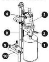
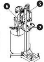
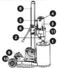
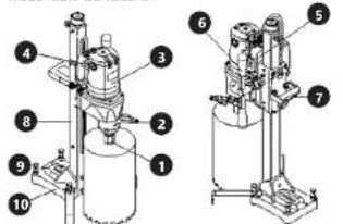
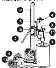
3.1. DEVICE DESCRIPTION
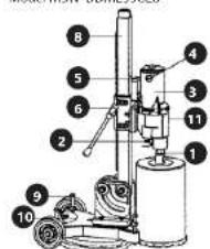
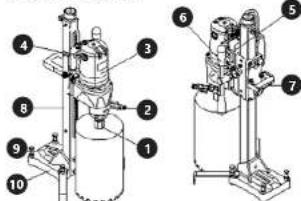
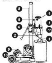
Model: MSW-DDM260, MSW-DDM300, MSW-DDM255G26
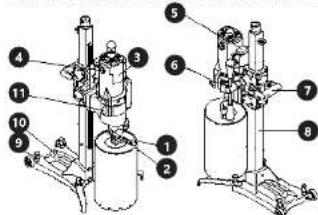
Model MSW-DDM205P24
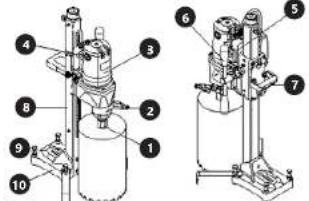
Model MSW DDM255G28
-
Spindle
-
Coolant valve
-
Motor
-
Motor carbon brushes cover
-
Only on switch
-
Lever for raising/ lowering the device
-
Handle
-
Guide fall
-
Attachment screws
-
Speed controller (not applicable to model MSW DDM260)
3.2. PREPARING FOR USE
3.2.1. APPLIANCE LOCATION
Ensure good ventilation in the room in which the device is being used. Keep the product away from hot surfaces. The device should always be used when positioned on an even, stable, clean, fireproof and dry surface, and be out of the reach of children and persons with limited mental and sensory functions. Position the device such that you always have access to the power plug. The power cord connected to the appliance must be properly grounded and correspond to the technical details on the product label.
3.2.2 BEFORE FIRST USE
-
Power source. Ensure that the power source which is utilized conforms to the power requirements specified on the product name.
-
Power switch. Ensure that the power switch is in the OFF position. If the plug is connected to a power receptacle while the power switch is in the ON position, serious accidents can occur.
-
Extension cord. When the work area has no power source, use an extension cord of sufficient thickness and rated capacity. The extension cord should be kept as short as possible.
-
Make sure that the coolant is connected to the machine through a 16 mm diameter tube. Lack of water may cause damage to the device. The maximum allowable liquid pressure is 0.12 MPa.
3.2.3. ASSEMBLY OF THE DEVICE'S ELEMENTS
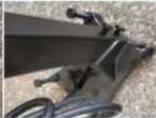
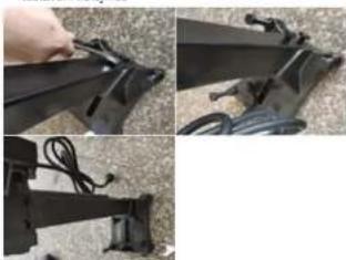
MODEL: MSW DDM260, MSW DDM205P24, MSW DDM300 • Installing the raise / lower lever
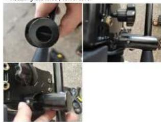
natural_image
Close-up of a mechanical component with a black cylindrical part inserted, showing close-up details (no visible text or symbols)- Installing the handle
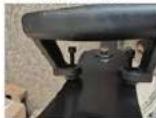
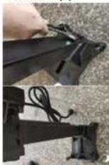
- Rail alignment
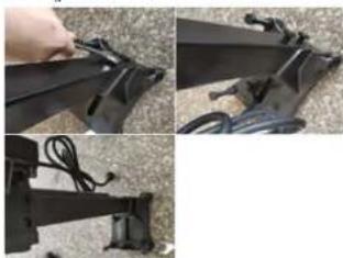
natural_image
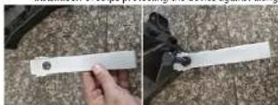
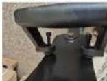
Close-up collage of mechanical components including a hand holding a black bracket and cable, with no visible text or symbols.Installation of strips protecting the device against tilting
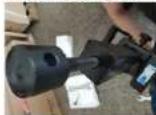
• Installing the top screw
Model: MSW DDM255G28, MSW DDM255G26
• Installing the bracket (only applicable to MSW DDM255G28)
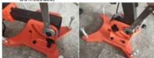
• Installing the raise/lower lever
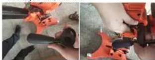
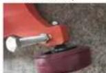
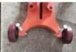
- Mounting the wheels (only applicable to MSW DDM255G28)
- Installing the handle
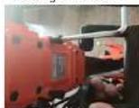
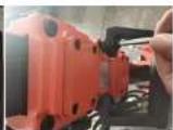
- Installing the top screw
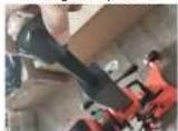
INSTALLATION OF THE COOLING FLUID HOSE AND THE DRILLS
coolant feed hose assembly: Slide hose end over device coolant feed valve. Once on, use a hose clamp to secure the hose in place.
- Mounting a core drill on the device. To mount a core drill on the spindle, screw it on clockwise.
ASSEMBLING THE DEVICE
Place the device on a stable and at surface. Attach it to the ground with mounting anchors
Place the device on a stable and level surface, use attachment anchors to mount the device to the surface
-
Place device base on the surface.
-
Mark the position of attachment holes.
-
Drill holes on the surface at the market positions.
-
Insert anchor into the drilled holes.
-
Align the holes in device bases with drilled holes and tighten the attachment screws.
-
Level the device. WARNING! If the device is not fastened so cloudy, it may it may turn or tip over uncontrollably.
3.3. CHECKING THE DEVICE
- Inspecting the tool.
Since the use of a dull tool will cause the motor to malfunction, it should be replaced with a new one without delay when abrasion is noted.
- Inspecting the mounting screws.
Regularly inspect all mounting screws and ensure that they are properly tightened. Should any of the screws be loose, retighten them immediately. Failure to do so could result in serious hazard.
- Maintenance of the motor.
The motor unit winding is the very "heart" of the power tool. Exercise due care to ensure the winding does not become damaged and/or wet with oil or water.
- Inspecting the carbon brushes.
the motor employs carbon brushes which are consumable parts. When they become worn or near the 'wear limit', it could result in motor trouble. When an auto-stop carbon brush is equipped, the motor will stop automatically. At that time, replace both carbon brushes with new ones. In addition, always keep carbon brushes clean and ensure that they slide freely within the brush holders.
3.4. DEVICE USE
WARNING! If an unusual smell or smoke appears during operation, please turn on the device immediately.
Model: MSW-DDM260, MSW-DDM205P24
Open the coolant valve and place the hose end in the work area. Turn on the device. Use lever for raising / lowering the device to adjust device height. Upon completing work, close the coolant valve, raise the device and turn it o . ATTENTION! Ensure that the core drill does not snag in the work-piece during operation.
Model MSW-DDM300, MSW-DDM255G28, MSW-DDM255G26
Open the coolant valve and put the pipe output in the work area. Before turning in a _m, make sure that the minimal rotation speed range is selected. Turn the device on via the built-in switch, adjust the speed control to the rotation speed of the required task and adjust the height of the device with the lower. To change the speed, switch on the device and use the regulator to set the appropriate speed. L (LOW) - lower gear, H (HIGH) - higher gear. After having successfully used it, turn on the cooling water valve, hold the device upwards, adjust the rotation speed to the smallest value and turn the device via the switch. ATTENTION! When working, make sure that the core drills are not in the workpiece.
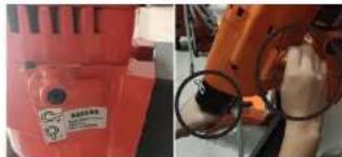
SHIFT ADJUSTMENT (Model: MSW-DDM300, MSW-DDM255G28, MSW-DDM255G26)
natural_image
Two industrial robotic arms: one with a red plastic component and the other with a black circular component inserted, both without any visible text or symbols.Stop the machine before shifting gears. Turning the knob during the machine's operation may damage the gears. Do not turn the knob when the machine is working, otherwise the gears may be damaged. NOTE: While adjusting the speed, you must rotate the spindle at the same time.
WARNING! If the rotation speed starts to drop while drilling, it means the motor is overloaded.
WARNING! The engine must not be coded with water or oil.
3.5. CLEANING AND MAINTENANCE
a) Unplug the mains plug and allow the device to cool completely before each cleaning, adjustment or replacement of accessories, or if the device is not being used.
b) Use only non-comosive cleaners to clean the surface. c) Store the unit in a dry, cool place, free from moisture and direct exposure to sunlight.
d) Do not spray the device with a water jet or submerge it in water.
e) Do not allow water to get inside the device through vents in the housing of the device.
f) Clean the vents with a brush and compressed air. g) The device must be regularly inspected to check its technical efficiency and spot any damage.
h) Use a soft, damp cloth for cleaning. i) Do not use sharp and/or metal objects for cleaning (e.g. a wire brush or a metal spatula) because they may damage the surface material of the appliance.
j): Do not clean the device with an acidic substance, agents of medical purposes, thinners, fuel, oils or other chemical substances because it may damage the device.
k) Do not wipe any plastic parts with solvents. Solvents such as gasoline, thinner, benzene, alcohol, ammonia and oil may damage and crack the plastic parts. Do not wipe them with such solvents. Wipe the plastic parts with a soft cloth lightly clamped with soapy water.
REPLACING CARBON BRUSHES
When the device is operated, carbon brushes steadily wear out. When the insulation tip integrated inside the brush gets revealed and touches the commutator it will trip the engine automatically. When this happens, both brushes must be replaced with new brushes of the same type. Inspect the carbon brushes after approx. 300 working hours. When the brushes are worn down to a length of about 7 mm, they should be replaced.
ATTENTION! BEFORE COMMENCING CARBON-BRUSH REPLACEMENT, make sure the device is switched o and the power cord is unplugged.
Replacing the carbon brushes:
- Unscrew the screw securing the carbon brushes on the side of the device housing.
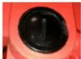
- Remove worn out carbon brush, insert new brush and tighten the screw. Replace the carbon brush on the other side of the housing in an analogous manner.
DISPOSING OF USED DEVICES
Do not dispose of this device in municipal waste systems. Hand it over to an electric and electrical device recycling and collection point. Check the symbol on the product, instruction manual and packaging. The plastics used to construct the device can be recycled in accordance with their markings. By choosing to recycle you are making a signal cant contribution to the protection of our environment. Contact local authorities for information on your local recycling facility.
DANE TECHNICZNE
Model MSW-DDM205P24
Model MSW-DDM255G28
natural_image
Close-up of mechanical components including a black cylindrical part and a hand holding a black cylindrical component (no visible text or symbols)
• Ustawienie szyny
Model: MSW-DDM255G28, MSW-DDM255G26
natural_image
Close-up of a red industrial robotic arm with a circular inset showing a close-up of the mechanical component (no visible text or symbols)Model MSW-DDM205P24
Model MSW-DDM255G28
natural_image
Close-up of mechanical components including a black cylindrical part and a hand holding a tool, with no visible text or symbols.• Montáž rukojeti
• Nastaveni kolejnice
natural_image
Close-up of a black mechanical component with attached cables and wires, shown in three sequential views (no text or symbols visible)natural_image
Close-up of a red robotic device with a circular annotation highlighting a mechanical component (no visible text or symbols)natural_image
Two industrial robotic arms: one red with a label and one orange with a magnified inset showing a mechanical component (no visible text or symbols)natural_image
Close-up of mechanical components including a black cylindrical part and a black bracket with tools, shown from three different angles (no text or symbols visible)natural_image
Close-up of a black mechanical component being adjusted, with visible wires and connectors (no text or symbols)natural_image
Two industrial robotic arms: one with a red plastic housing and label, the other with a close-up of a mechanical component (no visible text or symbols)natural_image
Close-up of a red industrial robotic arm with a circular inset showing a mechanical component (no visible text or symbols)Or, Dato / Place, Date / Mioves, Date / Lie, Date / Luequ, Date /Lugee / Pado / Maio, Duan

Umschaft / Signature / People / Signature / Exmo / Exmo / Post
Plotr R. Gajos
Ingenieur für die Richtinierübersprüfung der Produkte | Product Compliance Engineer | Inbypeler als. Ocony zgodniki produktów | Ingenieur responsable des analyses de conformité des produits | Ingegnerde della skurezza del prodotti | Ingeniero para la evaluación de la directiva de productos | Intenýr oddělení hodnocení hespebněti výrošků Name, Vomante, Stelle | Name, function, /rig. fárnatica, Função | Nom. Pristan, Portillo | e Cognome, Nome, Thalo de responsable, | Apellobas, Nambra, Panta, i Chines, Imaz, motá
nDoC
www.riskCE.pl
rev.08-02-2018
NAMEPLATE TRANSLATIONS
| MSW® MOTOR TECHNICE | ||||||||||||||||||||||||||||||||||||||||||||||||||||||||||||||||||||||||||||||||||||||||||||||||||||||||||||||||||||||
| 1 | Product Name: | 2 | Model: | |||||||||||||||||||||||||||||||||||||||||||||||||||||||||||||||||||||||||||||||||||||||||||||||||||||||||||||||||||
| 5 | Power: | 4 | Voltage/Frequency: | |||||||||||||||||||||||||||||||||||||||||||||||||||||||||||||||||||||||||||||||||||||||||||||||||||||||||||||||||||
| 5 | Current: | 6 | n0= | 7 | φ= | 8 | Weight: | |||||||||||||||||||||||||||||||||||||||||||||||||||||||||||||||||||||||||||||||||||||||||||||||||||||||||||||||
| 9 | Production Year: | |||||||||||||||||||||||||||||||||||||||||||||||||||||||||||||||||||||||||||||||||||||||||||||||||||||||||||||||||||||
| 10 | Serial No.: | |||||||||||||||||||||||||||||||||||||||||||||||||||||||||||||||||||||||||||||||||||||||||||||||||||||||||||||||||||||
| 11 | Manufacturer: expondo Polska sp. z o.o. sp. k. ul. Nowy Kisielin-Innowacyjna 7, 66-002 Zielona Góra | Poland, EU | 66-002 Zielona Góra | Poland, EU | ||||||||||||||||||||||||||||||||||||||||||||||||||||||||||||||||||||||||||||||||||||||||||||||||||||||||||||||||||||
| 1 | 2 | 3 | 4 | 5 | |||
| DE | Produktname | Model | Leistung | Spannung / Frequenz | Strum | ||
| EN | Product Name | Model | Power | Voltage / Frequency | Current | ||
| PL | Nazwa produktu | Model | Moc | Napięcie/ Częstotliwość | Prąd | ||
| CZ | Název výrobku | Model | Výkon | Napěti/Trekvence | Proud | ||
| FR | Nom du produit | Modèle | Puissance | Tension / Fréquence | Courant | ||
| IT | Nome del prodotto | Modello | Potenza | Tensione/ Frequenza | Corrente | ||
| ES | Nombre del producto | Modelo | Potencia | Voltaje/ Frecuencia | Intensidad de corrente | ||
| 6 | 7 | 8 | 9 | 10 | 11 | ||
| DE | Drochzahligoschwindigkeit ohne Überlastung | Maximaler Bohrdurchmesser | Gewicht | Produktionsjahr | Ordnungsnummer | Hersteller | |
| EN | No-load speed | Maximum drilling diameter | Weight | Production Year | Serial No. | Manufacturer | |
| PL | Prędkości obrotowa bez obchiążeni | Maksymalna srednica wiercenia | Ciężar | Rok produkcji | Numer serii | Producent | |
| CZ | Volnobężne otacky | Maximalni průměr vrtání | Hmotnost | Rok výroby | Seriové číslo | Výrobce | |
| FR | Vitosse de rotation sans charge | Diamètre maximal de forage | Poids | Année de production | Numero de serie | Fabricant | |
| IT | Velocità di rotazione senza carico | Diametro massimo di perforazione | Peso | Anno di produzione | Numero di serie | Produktore | |
| ES | Velocidad de rotación sin carga | Diámetro máximo de perforación | Peso | Año de producción | Numero de serie | Fabricante | |


NOTES/NOTIZENNOTES/NOTIZEN
For the disposal of the device please consider and act according to the national and local rules and regulations.
CONTACT
expondo Polska sp. z o.o. sp. k.


- DO NOT USE THE DEVICE UNLESS YOU HAVE THOROUGHLY READ AND UNDERSTOOD THIS USER MANUAL.
- LEGEND
- USAGE SAFETY
- ELECTRICAL SAFETY
- c) Do not touch the device with wet or damp hands.
- SAFETY IN THE WORKPLACE
- REMEMBER! When using the device, protect children and other bystanders.
- PERSONAL SAFETY
- 2.4.SAFE DEVICE USE
- Plotr R. Gajos
- CONTACT
Brand : MSW
Model : DDM300
Category : Drill