
S-Plasma 60P - Welding machine Stamos - Free user manual and instructions
Find the device manual for free S-Plasma 60P Stamos in PDF.


| Product Type | Welding / Plasma Cutter |
| Brand | Stamos |
| Model | S-Plasma 60P |
| Dimensions (L x W x H) | 490 x 210 x 370 mm |
| Net Weight | 19 kg |
| Power Supply | 400 V 3-phase, 14 A, 50/60 Hz |
| Cutting Current | 20 - 60 A |
| Duty Cycle at Max Current | 60% (6 min out of 10 min) |
| Max Cutting Thickness | Up to 22 mm |
| Cutting Width | 1,2 mm |
| Required Air Pressure | 6 bar, 170 l/min |
| Technology | MOSFET - efficiency 93% |
| Cooling | Axial fan |
| Solenoid valve | Yes, with post-flow gas for 10 s |
| Protections | Overvoltage, overheating (thermal) |
| Insulation Class | H |
| Protection Rating | IP21S |
| Standard | EN 60974-1, CE |
| Included Accessories | Plasma torch, ground clamp, air hose, pressure regulator + manometer, bag, wear parts |
| Maintenance | Regularly check the torch, electrode, diffuser and nozzle; replace worn consumables |
| Repairability | Spare parts available (contact customer service) |
| Warranty | Manufacturer's warranty (conditions in manual) |
Frequently Asked Questions - S-Plasma 60P Stamos
User questions about S-Plasma 60P Stamos
0 question about this device. Answer the ones you know or ask your own.
Ask a new question about this device
Download the instructions for your Welding machine in PDF format for free! Find your manual S-Plasma 60P - Stamos and take your electronic device back in hand. On this page are published all the documents necessary for the use of your device. S-Plasma 60P by Stamos.
USER MANUAL S-Plasma 60P Stamos
natural_image
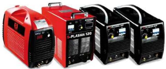
Three red and black S-PLASMA 120 welding machines with control panel, no visible text or symbols on the devices themselves.S-Plasma 50 / 60P / 80P / 120
BEDIENUNGSANLEITUNG
User manual | Manuel d'utilisation | Istruzioni per l'uso | Manual de instrucciones
DE
INHALT | CONTENU | CONTENT | CONTENUTO | CONTENIDO | TREŚĆ
Deutsch 3
English 22
Français 43
Polski 66
Español 86
natural_image
Close-up of a brass connector with hexagonal end (no text or symbols visible)9.

ERDUNG:
natural_image
Collection of automotive electrical components including a blue gas bag, white covers, pressure regulator, and various hoses (no text or symbols visible)natural_image
Product photo of six types of welding hoses and connectors, including black and teal tubing, brass fittings, and a pressure gauge (no text or symbols visible)DEDE
natural_image
Four red and black electronic welding machines labeled 'e-PLASMA 120' with control panels (no visible text beyond branding)S-Plasma 50 / 60P / 80P / 120
BEDIENUNSANLEITUNG
User manual | Manuel d'utilisation | Istruzioni per l'uso | Manual de instrucciones
www.STAMOS-GERMANY.de
EN
SAVE THIS MANUAL
Keep this manual for the safety warnings and precautions, assembly, operating, inspection, maintenance and cleaning procedures. Write the product's serial number in the back of the manual near the assembly diagram (or month and year of purchase if product has no number). Keep this manual and the receipt in a safe and dry place for future reference.
IMPROTANT SAFETY INFORMATION
In this manual, on the labeling, and all other information provided with this product: This is the safety alert symbol. It is used to alert you to potential personal injury hazards. Obey all safety messages that follow this symbol to avoid possible injury or death.
DANGER indicates a hazardous situation which, if not avoided, will result in death or serious injury.
WARNING: indicates a hazardous situation which, if not avoided, could result in death or serious injury.
CAUTION: used with the safety alert symbol, indicates a hazardous situation which, if not avoided, could result in minor or moderate injury.
NOTICE: is used to address practices not related to personal injury.
SAFETY WARNINGS AND PRECAUTIONS
WARNING: When using tool, basic safety precautions should always be followed to reduce the risk of personal injury and damage to equipment.
Read all instructions before using this tool!
WARNING!
READ AND UNDERSTAND ALL INSTRUCTIONS
Failure to follow all instructions listed below may result in electric shock fire, and/or serious injury. SAVE THESE INSTRUCTIONS.
WORK AREA PRECAUTIONS
- Keep your work area clean and well lit. Cluttered benches and dark areas invite accidents.
EN EN
- Do not operate power tools in explosive atmospheres, such as in the presence of flammable liquids, gases, or dust. Power tools create sparks which may ignite the dust or fumes.
- Keep bystanders, children, and visitors away while operating a power tool. Distractions can cause you to lose control. Protect others in the work area from debris such as chips and sparks. Provide barriers or shields as needed.
ELECTRICAL SAFETY
- Grounded tools must be plugged into an outlet properly installed and grounded in accordance with all codes and ordinances. Never remove the grounding prong or modify the plug in any way. Do not use any adapter plugs. Check with a qualified electrician if you are in doubt whether the outlet is properly grounded. If the tool should electrically malfunction or break down, grounding provides a low resistance path to carry electricity away from the user.
- Double insulated tools are equipped with a polarized plug (one blade is wider than the other). This plug will fit in a polarized outlet only one way. If the plug does not fit fully in the outlet, reverse the plug. If it still does not fit, contact a qualified electrician to install a polarized outlet. Do not change the plug in any way. Double insulation eliminates the need for the three wire grounded power cord and grounded power supply system.
- Avoid body contact with grounded surfaces such as pipes, radiators, ranges, and refrigerators. There is an increased risk of electric shock if your body is grounded.
- Do not expose power tools to rain or wet conditions. Water entering a power tool will increase the risk of electric shock.
- Do not abuse the Power Cord. Never use the Power Cord to carry the tool or pull the Plug from an outlet. Keep the Power Cord away from heat, oil, sharp edges, or moving parts. Replace damaged Power Cords immediately. Damaged Power Cords increase the risk of electric shock.
- When operating a power tool outside, sue an outdoor extension cord marker "W-A" or "W". These extension cords are rated for outdoor use, and reduce the risk of electric shock.
PERSONAL SAFETY
- Stay alert. Watch what you are doing, and use common sense when operating a power tool. Do not use a power tool while tired or under the influence of drugs, alcohol, or medication. A moment of inattentionwhile operating power tools may result in serious personal injury.
2 Dress properly. Do not wear loose clothing or jewelry. Contain long hair. Keep your hair, clothing, and gloves away from moving parts. Loose clothes, jewelry, or long hair can be caught in moving parts.
3. Avoid accidental staring. Be sure the Power Switch is off before plugging in. Carrying power tools with your finger on the Power Switch, or plugging in power tools with the Power Switch on, invites accidents.
4. Remove adjusting keys or wrenches before turning the power tool on. A wrench or a key that is left attached to a rotating part of the power tool may result in personal injury.
-
Do not overreach. Keep proper footing and balance at all times. Proper footing and balance enables better control of the power tool in unexpected situations.
-
Use safety equipment. Always wear eye protection. Dust mask, non-skid safety shoes, hard hat, or hearing protection must be used for appropriate conditions.
TOOL USE AND CARE
- Use clamps (not included) or other practical ways to secure and support the workpiece to a stable platform. Holding the work piece by hand ro against your body is unstable and may lead to loss of control.
2 Do not force the tool. Use the correct tool for your application. The correct tool will do the job better and safer at the rate for which it is designed. - Do not use the power tool if the Power Switch does not turn it on or off. Any tool that cannot be controlled with the Power Switch is dangerous and must be replaced.
- Disconnect the Power Cord Plug from the power source before making any adjustments, changing accessories, or storing the tool. Such preventive safety measures reduce the risk of starting the tool accidentally.
- Store idle tools out of reach of children and other untrained persons. Tools are dangerous in the hands of untrained users.
EN EN
- Maintain tools with care. Keep cutting tools maintained and clean. Properly maintained tools are less likely to bind and are easier to control. Do not use a damaged tool. Tag damaged tools "Do not use" until repaired
- Check for misalignment or binding of moving parts, breakage of parts, and any other condition that may affect the tool's operation. If damaged, have the tool serviced before using. Many accidents are caused by poorly maintained tools.
- Use only accessories that are recommended by the manufacturer for your model. Accessories that may be suitable for one tool may become hazardous when used on another tool.
SERVICE
- Tool service must be performed only by qualified repair personnel. Service or maintenance performed by unqualified personnel could result in a risk of injury.
- When servicing a tool, use only identical replacement parts. Use of unauthorized parts or failure to follow maintenance instructions may create a risk of electric shock or injury.
SPECIFIC SAFETY RULES
- Maintain labels and nameplates on the tool. These carry important information. If unreadable or missing, contact our sevice team for a replacement.
- Always wear the approved safety impact eye goggles and heavy work gloves when suing the tool. Using personal safety devices reduce the risk for injury. Safety impact eye goggles and heavy work gloves are available from Harbor Freight Tools.
- Maintain a safe working environment. Keep the work area well lit. Make sure there is adequate surrounding workspace. Always keep the work area free of obstructions, grease, oil, trash, and other debris. Do not use a power tool in areas near flammable chemicals, dusts, and vapors. Do not use this product in a damp or wet location.
- Avoid unintentional starting. Make sure you are prepared to begin work before turning on the tool.
- Never leave the tool unattended when it is plugged into an electrical outlet. Turn off the tool, and unplug it from its electrical outlet before leaving.
-
Always unplug the tool from its electrical outlet before performing and inspection, maintenance, or cleaning procedures.
-
Prevent eye injury and burns. Wearing and using the approved personal safety clothing and safety devices reduce the risk for injury.
a. Wear the approved safety impact eye goggles with a welding helmet featuring at least a number 10 shade lens rating.
b. Leather leggings, fire resistant shoes or boots should be worn when using this product. Do not wear pants with cuffs, shirts with open pockets, or any clothing that can catch and hold molten metal or sparks.
c. Keep clothing free of grease, oil, solvents, or any flammable substances. Wear dry, insulating gloves and protective clothing.
d. Wear an approved head covering to protect the head and neck. Use aprons, cape, sleeves, shoulder covers, and bibs designed and approved for welding and cutting procedures.
e. When welding/cutting overhead or in confined spaces, wear flame resistant ear plugs or ear muffs to keep sparks out of ears.
- Prevent accidental fires. Remove any combustible material from the work area.
a. When possible, move the work to a location well away from combustible; protect the combustibles with a cover made of fire resistant material.
b. Remove or make safe all combustible materials for a radius of 35 feet (10 meters) around the work area. Use a fire resistant material to cover or block all open doorways, windows, cracks, and other openings.
c. Enclose the work area with portable fire resistant screens. Protect combustible walls, ceilings, floors, etc., from sparks and heat with fire resistant covers.
d. If working on a metal wall, ceiling, etc., prevent ignition of combustibles on the other side by mobbing the combustibles to a safe location. If relocation of combustibles is not possible, designate someone to serve as a fire watch, equipped with a fire extinguisher, during the welding process and for at least one half hour after the welding is completed.
e. Do not weld or cut on materials having a combustible coating or combustible internal structure, as in walls or ceilings, without an approved method for eliminating the hazard.
f. Do not dispose of hot slag in containers holding combustible materials. Keep a fire extinguisher nearby and know how to use it.
g. After welding or cutting, make a thorough examination for evidence of fire. Be aware that easily visible smoke or flame may not be present for some time after the fire has started. Do not weld or the fire has started. Do not weld or
EN EN
h. Dangerously reactive or flammable gases, vapors, liquids, and dust.
i. Provide adequate ventilation in work areas to prevent accumulation of flammable gases, vapors, and dust. Do not apply heat to a container that has held an unknown substance or a combustible material whose contents, when heated, can produce flammable or explosive vapors. Clean and purge containers before applying heat. Vent closed containers, including castings, before preheating, welding, or cutting
WARNING INHALATION HAZARD: Welding and Plasma Cutting Produce TOXIC FUMES.
Exposure to welding or cutting exhaust fumes can increase the risk of developing certain cancers, such as cancer of the larynx and lung cancer. Also, some diseases that may be linked to exposure to welding or plasma cutting exhaust fumes are:
a. Early onset of Parkinson's Disease
b. Heart disease
c. Ulcers
d. Damage to the reproductive organs
e. Inflammation of the small intestine or stomach
f. Kidney damage
g. Respiratory diseases such as emphysema, bronchitis, or pneumonia
Use natural or forced air ventilation and wear a respirator approved by NIOSH to protect against the fumes produced to reduce the risk of developing the above illnesses.
-
Avoid overexposure to fumes and gases. Always keep your head out of the fumes. Do not breathe the fumes. Use enough ventilation or exhaust, or both, to keep fumes and gases from your breathing zone and general area.
-
Where ventilation is questionable, have a qualified technician take an air sampling to determine the need for corrective measures. Use mechanical ventilation to improve air quality. If engineering controls are not feasible, use an approved respirator.
-
Work in a confined area only if it is well ventilated, or while wearing an air-supplied respirator.
-
Follow OSHA guidelines for Permissible Exposure Limits (PEL's) for various fumes and gases.
- Follow the American Conference of Governmental Industrial Hygienists recommendations for Threshold Limit Values (TLV's) for fumes and gases.
-
Have a recognized specialist in Industrial Hygiene or Environmental Services check the operation and air quality and make recommendations for the specific welding or cutting situation.
-
Always keep hoses away from welding/cutting spot. Examine all hoses and cables for cuts, burns, or worn areas before each use. If any damaged areas are found, replace the hoses or cables immediately.
-
Read and understand all instructions and safety precautions as outlined in the manufacturer's Manual for the material you will weld or cut.
- Proper cylinder care. Secure cylinders to a cart, wall, or post, to prevent them from falling. All cylinders should be used and stored in an upright position. Never drop or strike a cylinder. Do not use cylinders that have been dented. Cylinder caps should be used when moving or storing cylinders. Empty cylinders should be kept in specified areas and clearly marked "empty."
- Never use oil or grease on any inlet connector, outlet connector, or cylinder valves.
-
Use only supplied Torch on this Inverter Air Plasma Cutter. Using components from other systems may cause personal injury and damage components within.
-
People with pacemakers should consult their physician(s) before using this product. Electromagnetic fields in close proximity to a heart pacemaker could cause interference to, or failure of the pacemaker.
-
USE PROPER EXTENSION CORD.
Make sure your extension cord is in good condition. When using an extension cord, be sure to sue one heavy enough to carry the current your product will draw. An undersized cord will cause a drop in line voltage resulting in loss of power and overheating. A 50 foot extension cord must be at least 12 gauges in diameter, and a 100 foot extension cord must be at least 10 gauges in diameter. If in doubt, use the next heavier gauge. The smaller the gauge number, the heavier the cord.
EN EN
DUTY CYCLE
The duty cycle is the percentage of the operating time (measured in minutes) of a 10-minute period in which the machine is used continuously in normal temperature conditions. If the values of the duty cycle are exceeded, this will trigger the overheat protection function, which stops the machine until it is cooled down to normal operating temperature. Repeated situations of exceeding the duty cycle values may lead to serious damage of the machine.
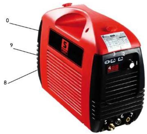
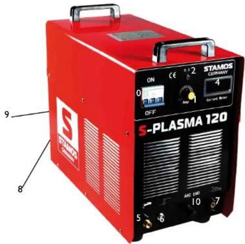
EXPLANATION:
0.

ON/OFF SWITCH
1.

CURRENT / CURRENT CONTROLLER: main current is adjustable.
2.

OVERLOAD / FAULT LED INDICATOR:
The indicator lights in the following two situations:
a) If the machine has malfunctioned and can not be operated.
b) If the cutting device has exceeded the standard working time the protection mode is initiated and the machine will stop functioning. This means that the machine is now being cooled in order to be able to restore temperature control again after the device has overheated. Therefore the machine is stopped. During this process, the red warning light on the front panel lights up. In this case it is not necessary to remove the power plug from the socket. The ventilation system may be left on in order to enhance the cooling of the machine. When the red light goes dark, this means that the temperature is now down to the normal level and the unit can be put back into operation.
3.

POWER INDICATOR: This indicator lights up after turning the machine on.
4.

LED - DISPLAY:
Displays the current amperage.
5.+6.

PORTS FOR PLASMA TORCH:
The high energy density of the plasma arc enables a high cutting speed with a warp-free cut quality. No special gas is required and the possibility to use regular air pressure along with easy handling of the unit are a guarantee of easy use in car bodies, containers, steel construction, the HVAC industry as well as in installations and plumbing.
7.

GROUNDING CABLE CONNECTION
8.

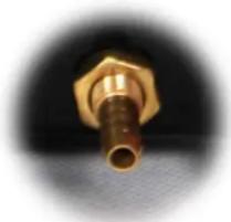
GAS/AIR CONNECTION
natural_image
Close-up of a brass connector with hexagonal end (no text or symbols visible)EN EN
9.

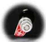
GROUNDING:
At the back of each welder there is a screw and a label to provide the necessary grounding. Before operating the unit it is necessary to ground the shell of the welding apparatus by means of a cable with not less than 6 mm diameter, in order to prevent potential problems caused by electricity leakages.
10.

ADDITIONAL POWER CONNECTION FOR THE PLASMA TORCH HOSE
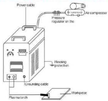
S-PLASMA 50 CONNECTION DIAGRAM
S-PLASMA 50
MOSFET:
This inverter uses MOS-FET technology. More than any other technology, the MOS-FET enables the achievement of maximum effectiveness. In comparison to the amount of electricity used the user will obtain disproportionate effectiveness. The result is an efficiency of 93%! Therefore the current is kept constant and ensures a perfect weld. Only by using the MOS-FET technology is it possible to keep this device as compact and lightweight.

NORMAL CURRENT:
The device uses a I-phase connection (230V +/- 10%).
EN EN
ACCESSORIES
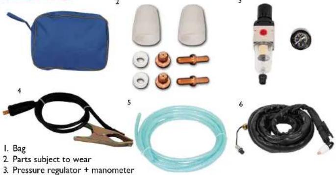
I. Bag
2. Parts subject to wear
3. Pressure regulator + manometer
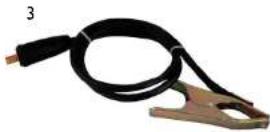
4. Grounding clamp cable
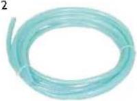
5. Air hose
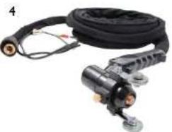
6. Plasma torch
POWER SUPPLY FOR S-PLASMA 60P /80P /120

HIGH POWER:
These devices use a 3-phase connection (380V +/- 10%).
The yellow-green wire is used as a PE protective wire connector. The three phases (black) can be freely connected to L1, L2 and L3 (please have it done only by a qualified electrician).
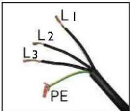
S-PLASMA 60P / 80P

MOSFET:
This inverter uses MOS-FET technology. More than any other technology, the MOS-FET enables the achievement of maximum effectiveness. In comparison to the amount of electricity used the user will obtain disproportionate effectiveness. The result is an efficiency of 93%! Therefore the current is kept constant and ensures a perfect weld. Only by using the MOS-FET technology is it possible to keep this device as compact and lightweight.
EN EN
ACCESSORIES
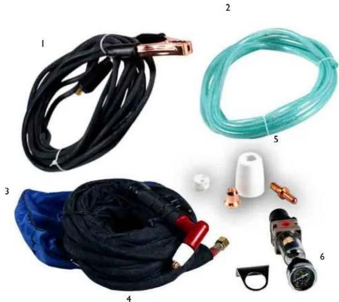
natural_image
Product photo of six types of welding hoses and connectors, including black, teal, blue, and mechanical components (no text or labels visible)- Grounding clamp cable
- Air hose
- Bag
- Plasma torch
- Parts subject to wear
- Pressure regulator + manometer
S-PLASMA 120
IGBT:
A bipolar transistor with insulated gate electrode (insulated gate bipolar transistor, IGBT) is a semiconductor that is increasingly used in power electronics, as the bipolar transistors offer certain advantages (e.g. good forwarding characteristics, high blocking voltage, robustness in welding equipment) and benefits characteristic of a field effect transistor (control with virtually no power consumption). Another advantage is a certain degree of resistance to short circuits, as IGBT limits the load current. IGBTs are a further development step of the vertical power MOSFETs.
EN EN
ACCESSORIES
1
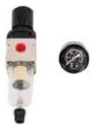
2
natural_image
Close-up of a black industrial welding torch with attached metal components (no visible text or symbols)I. Pressure regulator + manometer
2 Air hose
3. Grounding clamp cable
4. Plasma torch
TECHNICAL DETAILS
| S-Plasma 50 S- | Plasma 60P S-Plasma 80P S-Plasma 120 | |||
| Input voltage 230V 1-phase 400V | V 3-phase 400V | 3-phase 400V 3-phase | ||
| Frequency 50/60 Hz 50/60 Hz | 50/60 Hz 50/60 Hz | |||
| Input current 12A | 14A | 16A | 28A | |
| Open circuit voltage | 96V | 116V | 200V | 240V |
| Degree of protection of the housing | IP21S | IP21S | IP21S | IP21S |
| Insulation class | H | H | H | H |
| Surge protection | yes | yes | yes | yes |
| Cooling | Fan | Fan | Fan | Fan |
| Solenoid valve | yes | yes | yes | yes |
| Duty cycle ED at max. A | 60.00% | 60.00% | 60.00% | 60.00% |
| Cutting current | 20-50A | 20-60A | 20-80A | 20-120A |
| Air afterflow time | 10 sec | 10 sec | 10 sec | 10 sec |
| Ignition | Contact | Contact | Contact | High frequency |
| Material thickness | >14mm | >22mm | >27mm | >35mm |
| Cutting width | 1 mm | 1.2mm | 1.2mm | 1.4mm |
| Compressor connection | 4.5 bar, 30-1001/min. | 6 bar, 1701/min. | 6 bar, 1701/min. | 6 bar, 1701/min. |
| Built in accordance with | EN 60974-1 | EN 60974-1 | EN 60974-1 | EN 60974-1 |
| Conformity with EC directives | CE | CE | CE | CE |
| Weight (net) | 9 kg | 19 kg | 20 kg | 36 kg |
| Dimensions L/H/W (mm) 380x | 290x160 490x2 | 10x370 495x215x | 375 500x370x350 | |
EN EN
Unpack all the items out of the box and make sure that you have received all items listed on the packing list.
B. Work environment
Make sure that the work area is well ventilated. The unit is cooled by an axial fan that provides an air flow for the electronics through the rear panel.
(Note! The housing must be installed in a way that ensures that the vent holes are closer to the front of the machine). At least 15 cm at the front and 15 cm on each side should be left to enable cleaning. If the machine is operated without adequate cooling, the length of the duty cycle will be reduced greatly.
C. Cable connections
Each unit is equipped with a main power cable, which is responsible for providing current and voltage to the device. If the device is connected to power which exceeds the required voltage, or if the wrong phase is set, it may lead to severe damage to the unit. This is not covered by the warranty for the equipment and the user will be responsible for such situations.
D. Torch connection
Connect the torch to the inverter by connecting the air tube that is attached at the end of the torch to the torch connector on the front part of the machine. Ensure that the connection is secure by tightening it slightly with a spanner. However you should not make it too tight.
PISTOL ASSEMBLY (S-Plasma 50/60P/80P)
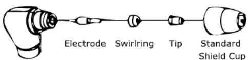
A. Assembling the pistol
Put the pistol the protective cap facing up and turn the cap away from the gun. (The protective cap holds the tip, the ceramic swirl ring and the electrode together). Remove the cap, the ceramic swirl ring and the electrode. Assemble the electrode, the ceramic swirl ring and the tip back together. Replace worn parts if necessary. Put the protective cap on the head of the pistol and screw it on with your hand until it is snug. If any resistance is present during this process, check the thread and the arrangement of the items before resuming work.
NOTE
In case of some pistols with no reversible electrodes it is necessary to tighten the electrode further by using a pair of pliers in order to ensure a reliable electrical connection.
INSTRUCTIONS FOR USE
A. The beginning
Turn the power switch to „ON“. Take up a position at the unit in which you can easily read the air pressure from the device. Press the pistol switch (air will flow out from the pistol), adjust the air valve to approximately 6-7 (bar) and press the pistol switch again.
NOTE
The generally accepted value range of air pressure is 5-8 bar. You can now perform tests as needed, but you should remember not to reduce the air pressure too much because it may damage the consumables. Secure the grounding clamp on the workpiece. Connect the clamp to the main part of the workpiece and not to part which is to be removed.
B. Cutting
I. Drag-cutting
Hold the tip of the pistol above the workpiece, press the pistol switch and move the pistol tip until it comes into contact with the workpiece and the cutting arc is established. Once the cutting arc is generated you may move the pistol in the desired direction with the tip of the pistol always at a slight angle and maintaining contact with the workpiece. This working method is called drag cutting. Excessively rapid movements should be avoided. A sign of this are sparks, which can spray from the top of the workpiece. Move the pistol with a speed that ensures gathering of the sparks under the workpiece and before proceeding make sure that the material is cut through completely. Set the drag speed as required.
EN
2. Weekly activities
Verify the proper operation of the air flow. Blow off or suck in dust or dirt from the entire machine, including the air filter.
3. Distance cutting
In some cases it may be advantageous to perform cutting with the tip of the pistol at a height of approximately 1/16" to 1/8" above the workpiece in order to reduce the amount of material which is once again blown back into the tip and to maximize the penetration of thick cuts through the material. Distance cutting should be used when penetration cutting or or grooving is executed. The distance technique may also be used when cutting sheet metal in order to minimize the risk of material back splashing, which could damage the tip.
4. Drilling through
In order to drill through the tip of the pistol should be placed at approximately 3.2 mm above the workpiece. Hold the pistol at a slight angle to deflect the sparks away from yourself and the tip of the pistol. Activate the main arc and lower the tip of the pistol until the main cutting arc is initiated and sparking begins. Initiate drilling on a test item which is no longer in use and continue with the drilling on the previously defined cut line once the test hole is completed without problems.
MAINTENANCE
Check the pistol for wear damage, cracks or exposed wire sections. Replace or repair any such defects before using the device. A heavily worn pistol tip/nozzle contributes to the reduction of speed, voltage drops and crooked cuts. An indication of a worn pistol tip/nozzle is an elongated or oversized nozzle opening. The external part of the electrode may be recessed no more than 3.2 mm. Replace the electrode if it is worn, as indicated by the above measurement. If the cap cannot be re-attached easily, check the thread.
STAMOS®
WELDING GROUP
natural_image
Four red and black PLASMA 120 welding machines with visible control knobs and branding (no readable text or symbols on devices)S-Plasma 50 / 60P / 80P / 120
BEDIENUNSANLEITUNG
User manual | Manuel d'utilisation | Istruzioni per l'uso | Manual de instrucciones
FR FR
CONSERVEZ CE MANUEL
COURANT CUMULE: Courant principal ajustable
2

DEL DE SURCHARGE / INCIDENT:
natural_image
Close-up of a brass connector with hexagonal head and threaded shaft (no text or symbols visible)9.

PRISE DE TERRE:
natural_image
Collection of automotive electrical components including a blue gas bag, white covers, pressure tool, black clamp, coiled hoses, and cable (no text or symbols visible)natural_image
Product photo of industrial gas welding equipment including hoses, hoses, and pressure gauges (no visible text or labels)natural_image
Four electronic welding machines with red and black models, no visible text or symbols on the devices themselves.S-Plasma 50 / 60P / 80P / 120
INSTRUKCJA OBSŁUGI
User manual | Manuel d'utilisation | Istruzioni per l'uso | Manual de instrucciones
PL
natural_image
Close-up of a brass connector with hexagonal head and central shaft (no text or symbols visible)9.

UZIEMIENIE:
MOSFET:
natural_image
Product photo of six types of gas welding hoses and connectors, including black cables, coiled hoses, and a pressure regulator (no text or symbols visible)natural_image
Four different types of industrial welding tools and pressure gauges, shown in separate views (no text or labels visible)natural_image
Four red and black electronic welding machines labeled 'PLASMA 120' (no visible text or symbols on devices)S-Plasma 50 / 60P / 80P / 120
natural_image
Close-up of a brass connector with hexagonal end caps (no text or symbols visible)9.

TOMA DE TIERRA
natural_image
Collection of automotive electrical components including a blue foam seal, pressure regulator, and various hoses (no text or labels visible)natural_image
Collection of automotive exhaust gas fittings and components including hoses, hoses, and a pressure regulator (no text or labels visible)natural_image
Close-up of a black industrial hose with attached mechanical components (no visible text or symbols)We hereby certify that the appliances listed in this manual are CE compliant.
FR
For the disposal of the device please consider and act according to the national and local rules and regulations.
CONTACT
- S-Plasma 50 / 60P / 80P / 120
- DE
- DEDE
- EN
- SAVE THIS MANUAL
- IMPROTANT SAFETY INFORMATION
- SAFETY WARNINGS AND PRECAUTIONS
- WORK AREA PRECAUTIONS
- EN EN
- ELECTRICAL SAFETY
- PERSONAL SAFETY
- TOOL USE AND CARE
- SERVICE
- SPECIFIC SAFETY RULES
- WARNING INHALATION HAZARD: Welding and Plasma Cutting Produce TOXIC FUMES.
- DUTY CYCLE
- EXPLANATION:
- GROUNDING:
- MOSFET:
- NORMAL CURRENT:
- POWER SUPPLY FOR S-PLASMA 60P /80P /120
- ACCESSORIES
- TECHNICAL DETAILS
- Work environment
- Cable connections
- Torch connection
- Assembling the pistol
- NOTE
- INSTRUCTIONS FOR USE
- The beginning
- Cutting
- Drag-cutting
- Weekly activities
- Distance cutting
- Drilling through
- MAINTENANCE
- STAMOS®
- WELDING GROUP
- FR FR
- CONSERVEZ CE MANUEL
- PL
- TOMA DE TIERRA
- FR
- CONTACT
Brand : Stamos
Model : S-Plasma 60P
Category : Welding machine