
Q1961-XTE - Surveillance Camera AXIS - Free user manual and instructions
Find the device manual for free Q1961-XTE AXIS in PDF.

| Product Type | Surveillance Camera |
| Brand | Axis |
| Model | Q1961-XTE |
| Ingress Protection | IP66/IP68 (10 bar, 30 min) |
| Operating Temperature Range | -40 °C to +85 °C |
| Power Supply | Power over Ethernet (PoE) or limited power source (LPS) ≤100 W, ≤5 A |
| Cable Gland | M20 x 1.5, Ex certified (IECEx BVS 17.0101X) |
| Cable Gland Material | Nickel-plated copper, nitrile rubber (NBR) |
| Compatible Cable Diameter | 8 to 13 mm |
| Maximum Installation Altitude | ≤2,000 m |
| Capacitance of Accessible Metal Parts | 85.4 pF |
| Internal Battery | Lithium coin cell 3.0 V (contains EGDME) |
| Main Functions | Video surveillance, Ex certification for explosive atmospheres, outdoor installation |
| Maintenance and Cleaning | Clean with a soft damp cloth using warm water; do not use harsh chemicals |
| Electrical Safety | Use a shielded (STP) network cable connected to ground; comply with local regulations |
| Spare Parts and Reparability | No user-serviceable parts; contact Axis support |
| General Information | Full manual at axis.com; firmware updates at axis.com/support |
Frequently Asked Questions - Q1961-XTE AXIS
User questions about Q1961-XTE AXIS
0 question about this device. Answer the ones you know or ask your own.
Ask a new question about this device
Download the instructions for your Surveillance Camera in PDF format for free! Find your manual Q1961-XTE - AXIS and take your electronic device back in hand. On this page are published all the documents necessary for the use of your device. Q1961-XTE by AXIS.
USER MANUAL Q1961-XTE AXIS
natural_image
Technical line drawing of a mechanical device with flanged housing and cylindrical body (no text or symbols)Installation guide
Read through this installation guide carefully before you install the product. Keep the installation guide future reference.
Electromagnetic compatibility (EMC)
This equipment has been designed and tested to ful applicable standards for:
- Radio frequency emission when installed according to the instructions and used in its intended environment.
- Immunity to electrical and electromagnetic phenomena when installed according to the instructions and used in its intended environment.
USA
This device complies with part 15 of the FCC Rules. Operation is subject to the following two conditions:
- This device may not cause harmful interference, and
- this device must accept any interference received, including interference that may cause undesired operation.
This equipment has been tested using a shielded network cable (STP) and found to comply with the limits for a Class A digital device, pursuant to part of the FCC Rules. These limits are designed to provide reasonable protection against harmful interference when the equipment is operated in a commercial environment. This equipment generates, uses, and can radiate radio frequency energy and, if not installed and used in accordance with the instruction manual, may cause harmful interference to radio communications. Operation of this equipment in a residential area is likely to cause harmful interference in which case the user will be required to correct the interference at his own expense. The product shall be connected using a shielded network cable (STP) that properly grounded.
Contact information
Axis Communications Inc.
300 Apollo Drive
Chelmsford, MA 01824
United States of America
Tel: +1 978 614 2000
Canada
This digital equipment fulfills the requirements for RF emission according to the Class A limit of EN 55032. The product shall be connected using a shielded network cable (STP) that is properly grounded. Notice! This is a Class A product. In a domestic environment this product may cause RF interference, in which case the user may be required to take adequate measures.
Australia/New Zealand
This digital equipment fulfills the requirements for RF emission according to the Class A limit of AS/NZS CISPR 32. The product shall be connected using a shielded network cable (STP) that is properly grounded. Notice! This is a Class A product. In a domestic environment this product may cause RF interference, in which case the user may be required to take adequate measures.
Japan
When this product has reached the end of its useful life, dispose of it according to local laws and regulations. For information about your nearest designated collection point, contact your local authority responsible for waste disposal. In accordance with local legislation, penalties may be applicable for incorrect disposal of this waste.
Europe

This symbol means that the product shall not be disposed of together with household or commercial waste. Directive 2012/19/EU on waste electrical and electronic equipment (WEEE) is applicable in the European Union member states. To prevent potential harm to human health and the environment, the product must be disposed of in an approved and environmentally safe recycling process. For information about your nearest designated collection point, contact your local authority responsible for waste disposal. Businesses should contact the product
supplier for information about how to dispose of the product correctly.
This product complies with the requirements of Directive 2011/65/EU and 2015/863 on the restriction of the use of certain hazardous substances in electrical and electronic equipment (RoHS).
China

This product complies with the requirements of
SJ/T 11364-2014, Marking for the restriction of hazardous substances in electrical and electronic products.
Declaration of the Presence Condition of the Restricted Substances Marking.
限用物質含有情況標示
Warranty information
For information about Axis' product warranty and thereto related information, go to axis.com/warranty.
Support
Should you require any technical assistance, please contact your Axis reseller. If your questions cannot be answered immediately, your reseller will forward your queries through the appropriate channels to ensure a rapid response. If you are connected to the Internet, you can:
- download user documentation and software updates
- find answers to resolved problems in the FAQ database, search by product, category, or phrase
• report problems to Axis support staff by logging in to your private support area - chat with Axis support staff
- visit Axis Support at axis.com/support
Learn more!
Visit Axis learning center axis.com/learning for useful trainings, webinars, tutorials and guides.
ココンタタククトト情情報報
Axis Ex AB
Gränden 1
223 69 Lund
Sweden
電話: +46 46 272 18 00
Fax: +46 46 13 61 30
axis.com
保保证証情情報報
- The Axis product shall be used in compliance with local laws and regulations.
• This product is for professional use.
• Install this product at a safe distance from children. - Store the Axis product in a dry and ventilated environment.
- Avoid exposing the Axis product to shocks or heavy pressure.
- Avoid exposing the Axis product to vibration.
- Do not install the product on unstable poles, brackets, surfaces or walls.
- Do not install the product on vibrating poles, brackets, surfaces or walls.
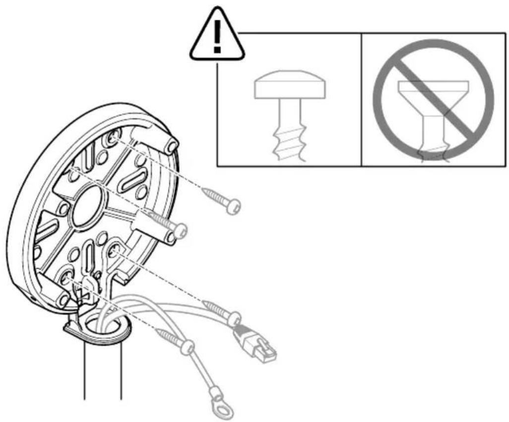
- Use only applicable tools when installing the Axis product. Using excessive force with power tools could cause damage to the product.
- Use a soft cloth dampened with pure lukewarm water to clean the device.
- Don't use chemicals such as window cleaner or acetone to clean your device.
- Use only accessories that comply with the technical specification of your product. These can be provided by Axis or a third party. Axis recommends using Axis power source equipment compatible with your product.
- Use only spare parts provided by or recommended by Axis.
- Do not attempt to repair the product yourself. Contact Axis support or your Axis reseller for service matters.
- The power supply shall be plugged in to a socket outlet installed near the product and shall be easily accessible.
- Use a limited power source (LPS) with a rated output power limited to ≤ 100 W and a rated output current limited to ≤ 5 A.
Français
| Version Date Details | ||
| 1.0 2024-02-02 First release | ||
| 2.0 2024-06-03 Updated illustrations and change of part number to 3086320 (old part number: 2566564) | ||
| 3.0 2024-12-18 New part number | Updates to Specific Conditions of use: Pollution degree 2 removed | |
EN
Specific conditions of use
WARNING
Always refer to the product certificates for any specific conditions of use.
- Take precautions to minimise the risk of electrostatic charging. For more information, see Maintenance, on page 16.
- Equipment must not be exposed to impact energy exceeding 2 Joules to the window, and 4 Joules to the rest of the body.
- Orientation of the product must be in accordance with the installation instructions. The device must not be surrounded with more dust than the surfaces can retain.
- Capacitance of accessible metal parts of the equipment is 85.4 pF and shall be considered in the specific application.
Installation
WARNING
All installation and maintenance must be carried out by a suitably skilled electrician in accordance with all local and national standards and codes of practice e.g. NFPA70 (National Electrical Code), CSA C22.1 (Canadian Electrical Code, Part I Safety Standard for Electrical Installations), IEC/EN 60079-14 (Explosive atmospheres - Electrical installations design, selection and erection) and IEC/EN 60079-17 (Explosive atmospheres. Electrical installations inspection and maintenance).
- The installer must comply with the technical data attached.
- Ensure that all items are approved and certified for the environmental and installation requirements. Check the rating label to ensure that the device is being used within the correct ambient temperature and environmental conditions, and that the power supply is suitable.
-
The device must be installed ≤ 2000 m above sea level.
-
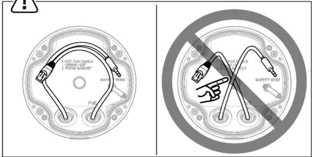
Cable entry points can reach a temperature of 81.1°C. Use a suitable cable for the end application.
- Modifications or design changes to the device are not allowed.
- Safety rules and national regulations must be observed.
- Never install the device in an area that may exceed the ambient temperature range.
- Aggressive substances may require extra protection.
- The device must be protected by additional means of protection if it is exposed to excessive external stress, that is vibration, heat or impact.
- If the device is not used in a manner specified by the manufacturer, the device's protection may be impaired. Incoming cables must comply with the national standards.
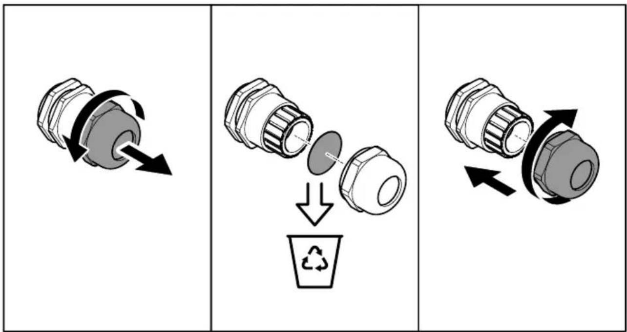
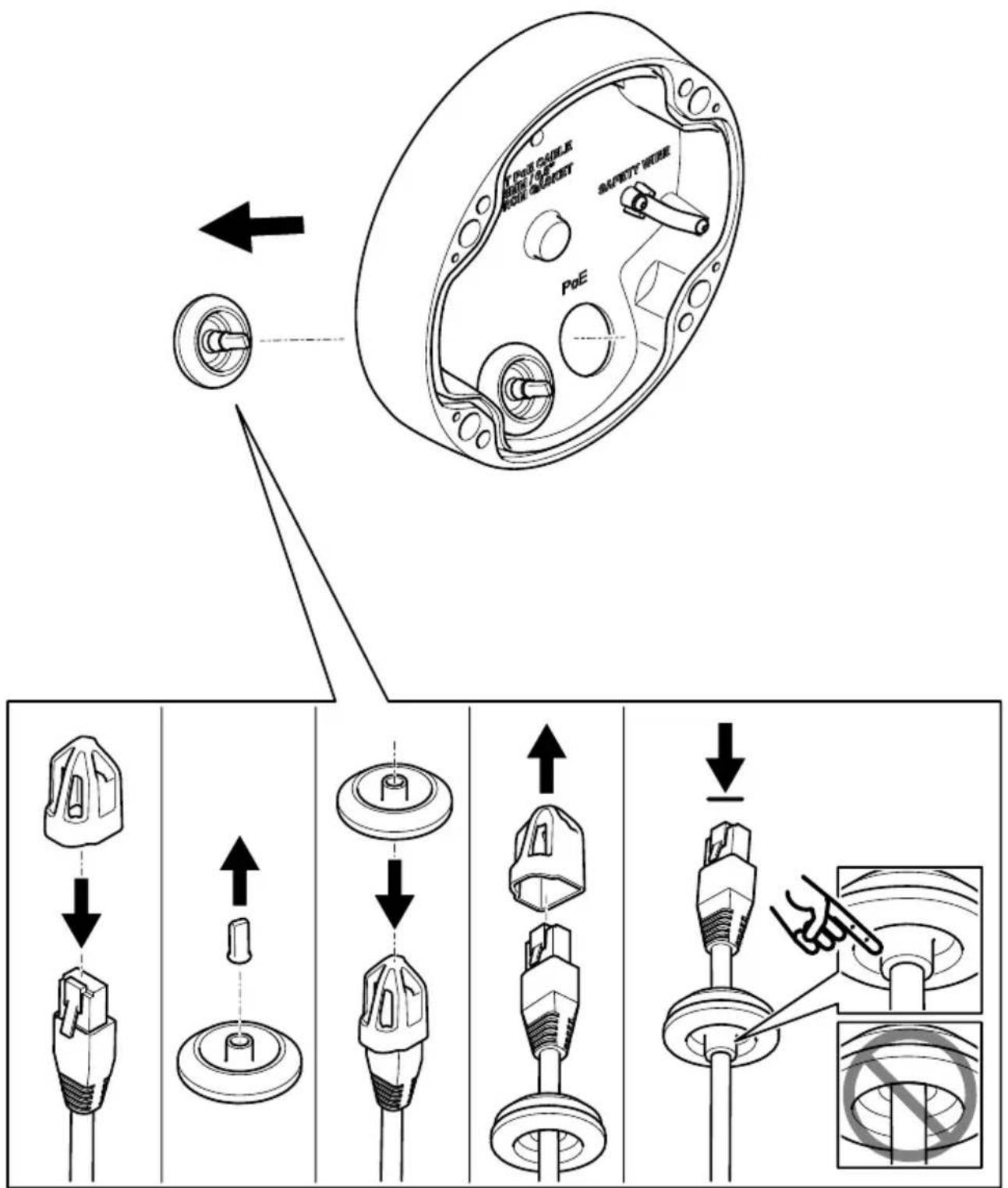
- If the device is re-installed or the incoming cables are re-wired, new grommets must be used. The rubber of the grommet must be fresh and the grommet must be unused.
- Replacement parts may only be installed using component parts as specified by Axis Ex AB.
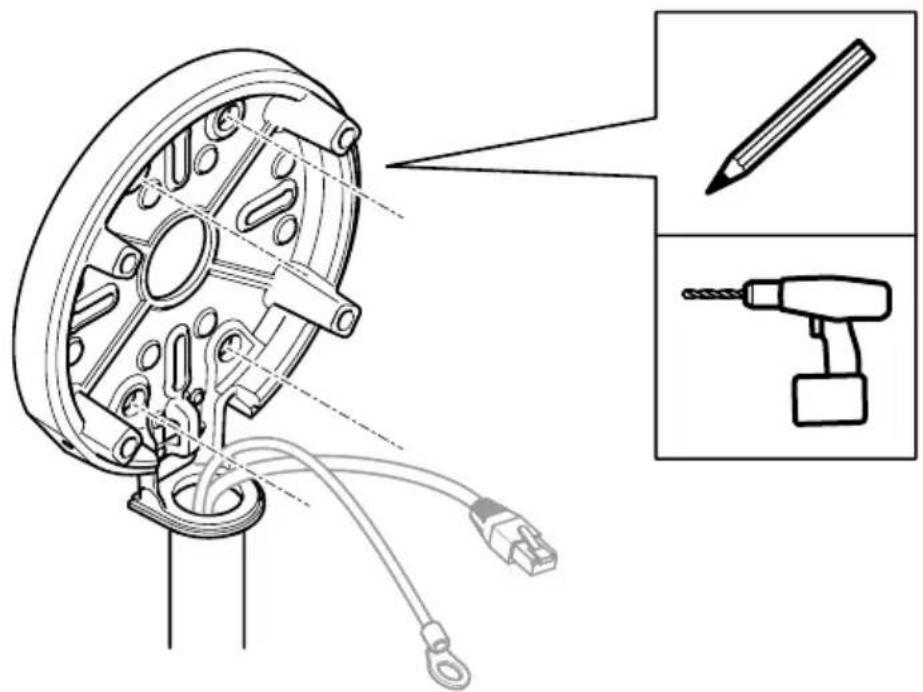
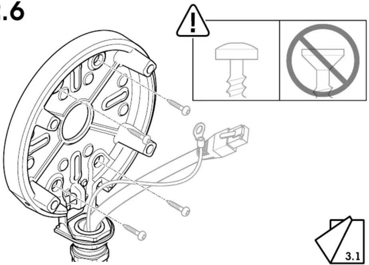
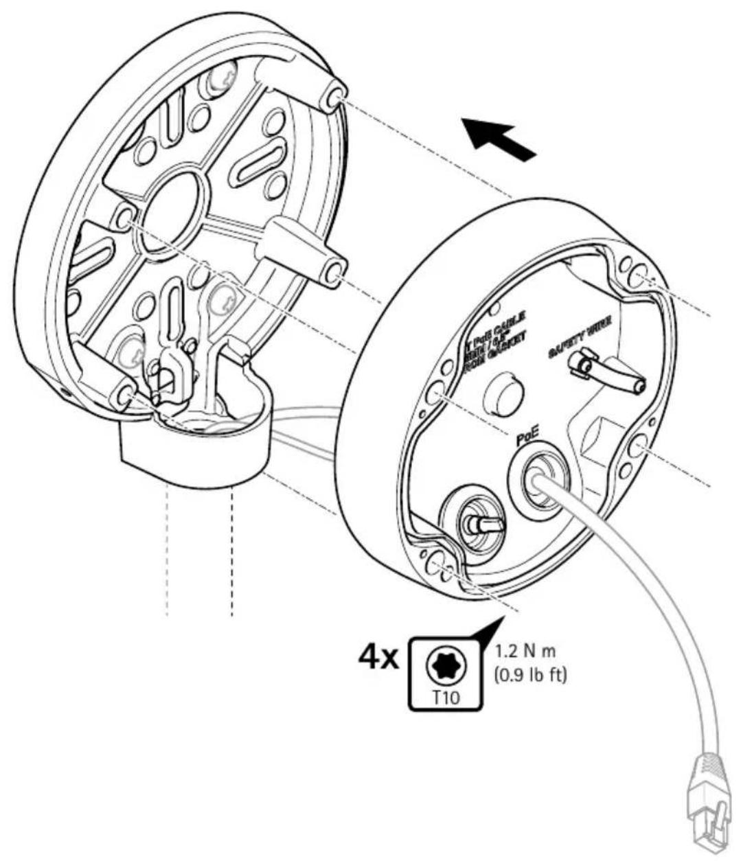
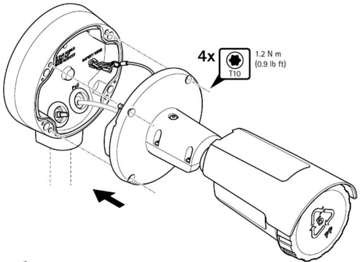
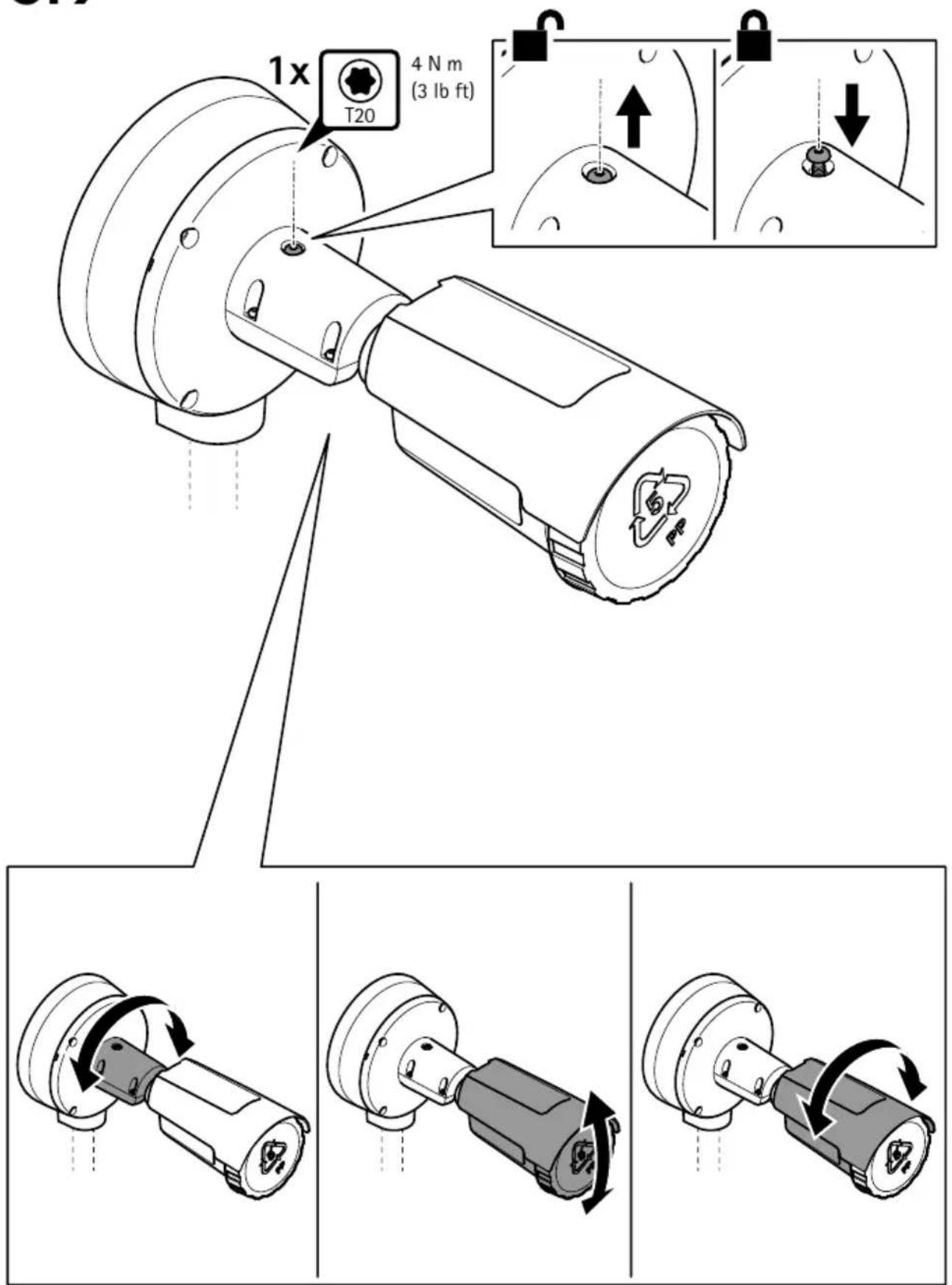
- Fixing brackets must be tightened upon installation. Suitable screws must be used. See the device's datasheet for information about the weight.
- Install in an appropriate environment, according to IEC/EN/UL 60079-14 and IEC/EN/UL 60079-17.
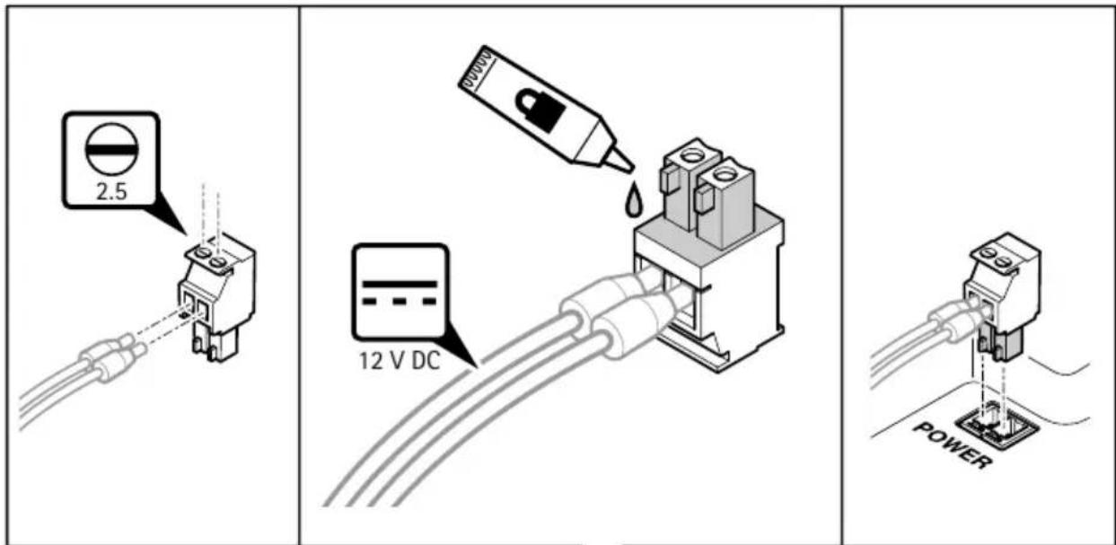
- The power connector must be glued when connected. Apply glue on the male connector.
| Manufacturer Glue type Temperature range of | adhesive |
| Gorilla Glue Gorilla Super Glue -55°C to +100°C | |
| Henkel LOCTITE 402 -40°C to +135°C | |
| Permabond Permabond 801 -55°C to +130°C | |
| Permabond Permabond 802 -55°C to +160°C | |
| Permabond Permabond 820 -55°C to +200°C |
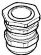
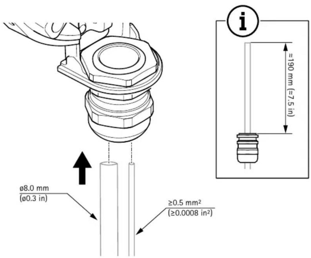
Cable gland
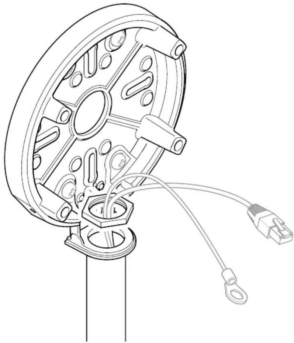
To fulfil JPEx certification, this device must be installed with the specified cable gland, included with the unit.
| Manufacturer Jacob GmbH | |
| Thread type M20x1.5 | |
| Model name K100-1020-00-EX | |
| Ex marking Ex eb IIC Gb | Ex tb IIIC Db |
| IECEx certificate number IECEx BVS 17.0101X | |
| Degree of protection according to EN/IEC 60529 | IP66/IP68 (10 bar, 30 min)* |
| Operating temperature -40 °C to +85 °C | |
| Material Nickel plated brass | Nitrile rubber NBR |
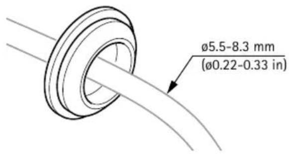
| Cable diameter 8-13 mm | |
| Specific conditions of use to be considered installation with this device | The cable gland is tested with a reduced tensile force (25%) in accordance with claus A.3.1 of IEC 60079-0. It may only be used fixed installation of Group II and Group III apparatus. The user shall ensure adequate clamping of the cable. |
EN
* The Ingress Protection of the device is not relying on the cable gland. Instead it is provided by cable grommets inside the equipment.
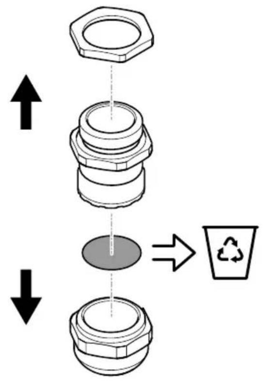
Cable gland installation
WARNING
Hazard due to modification or alteration! Explosion protection at risk!
The cable gland may not be modified or altered.
Before installation:
- Ensure that the cable gland is undamaged. Check the thread, sealing rings and o-ring-sealings.
- Remove the dust cap.
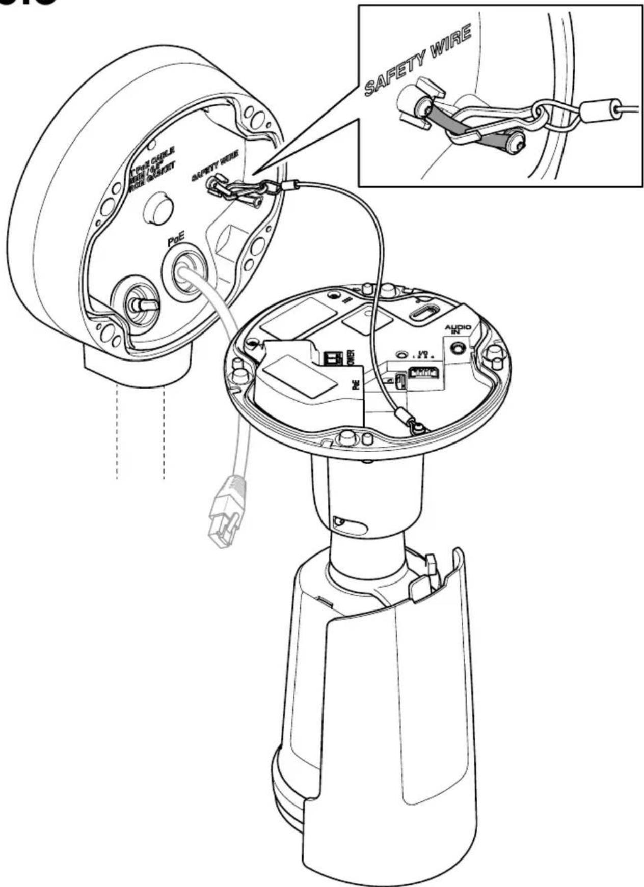
- Additional reliable strain relief/anchorage must be guaranteed for the inserted and fixed installed cables.
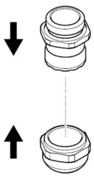
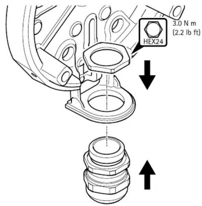
During installation:
- Make sure that the cable gland is fully screwed into the connecting thread.
- Ensure proper seating of the sealing rings and o-ring-sealings.
- Ensure that the specified protection grades are upheld.
- To prevent loosening, if necessary use an additional hexagonal locknut or suitable thread locking fluid.
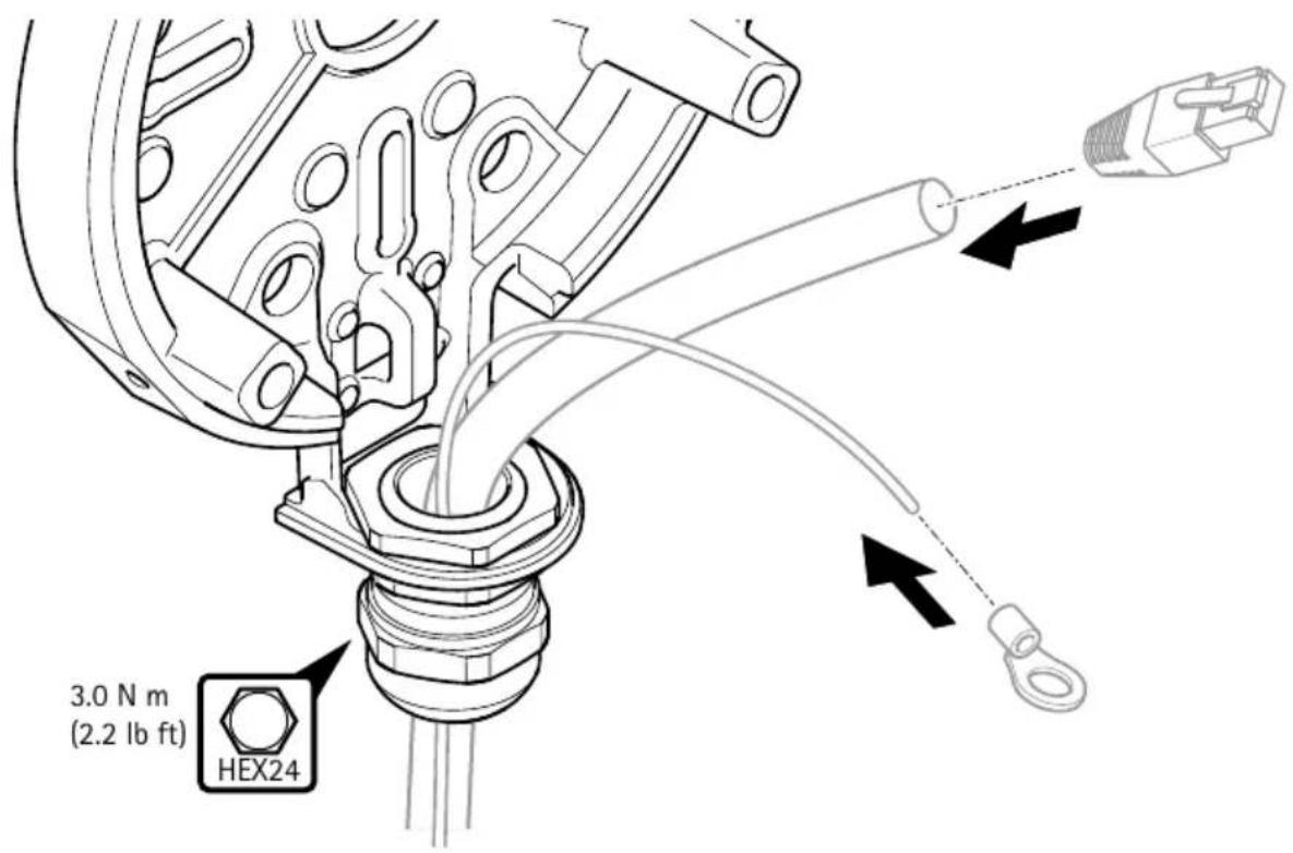
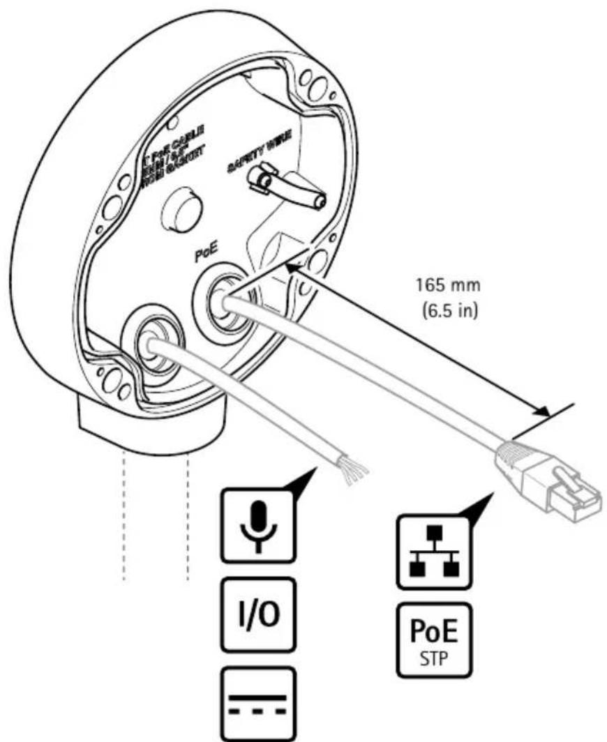
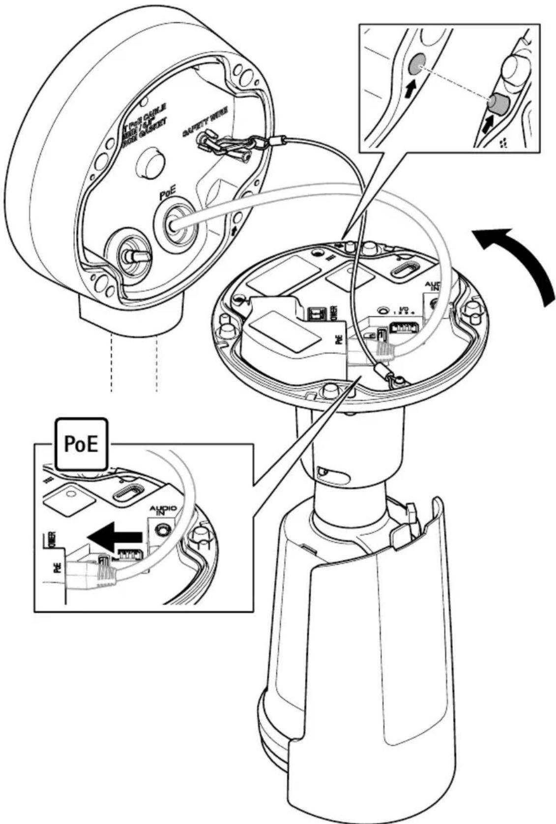
Wiring
WARNING
Disconnect the device from the power source before starting any operations.
- Ensure that the voltage is correct before beginning any maintenance or connections.
- The device must be electrically installed and serviced by skilled persons.
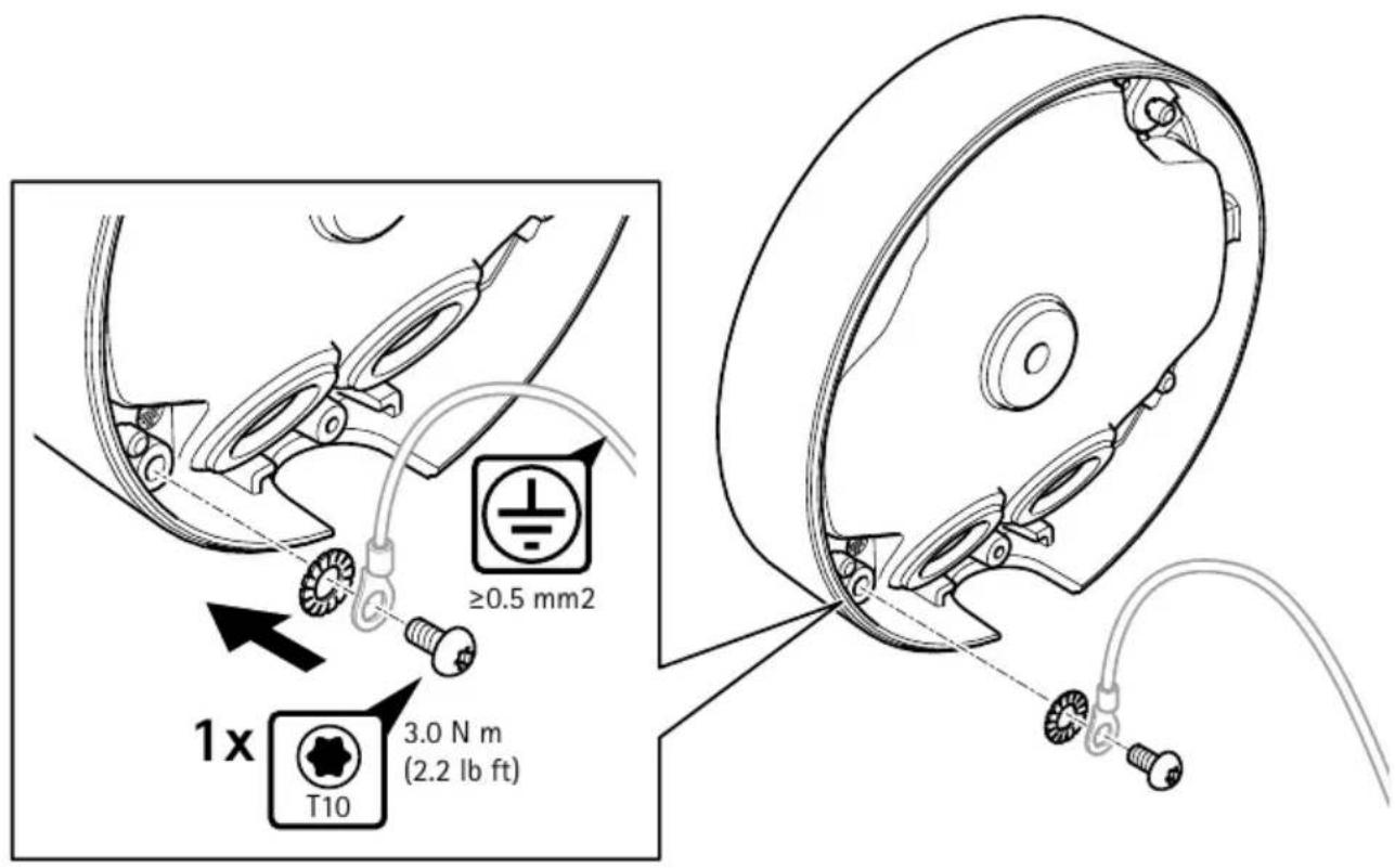
- Earth connection ferrule should be of a suitable material to avoid corrosion.
- Use suitably color coded conductors or other means of identification. Earthing conductors should be green and yellow.
- Use only certified cable devices that matches the end application.
- In each installation, main equipotential bonding conductors shall connect to the main earthing terminal extraneous conductive-parts of that installation. Where supplementary equipotential bonding is necessary, it shall connect together the exposed conductive-parts of the device in the circuits concerned and extraneous-conductive-parts. The external bonding cable shall be at least 4 mm
Maintenance
The device does not contain any servicable parts. No covers or seals should be removed.
WARNING
It is strictly prohibited to carry out any attempt of repairs other than by approved and trained personnel.
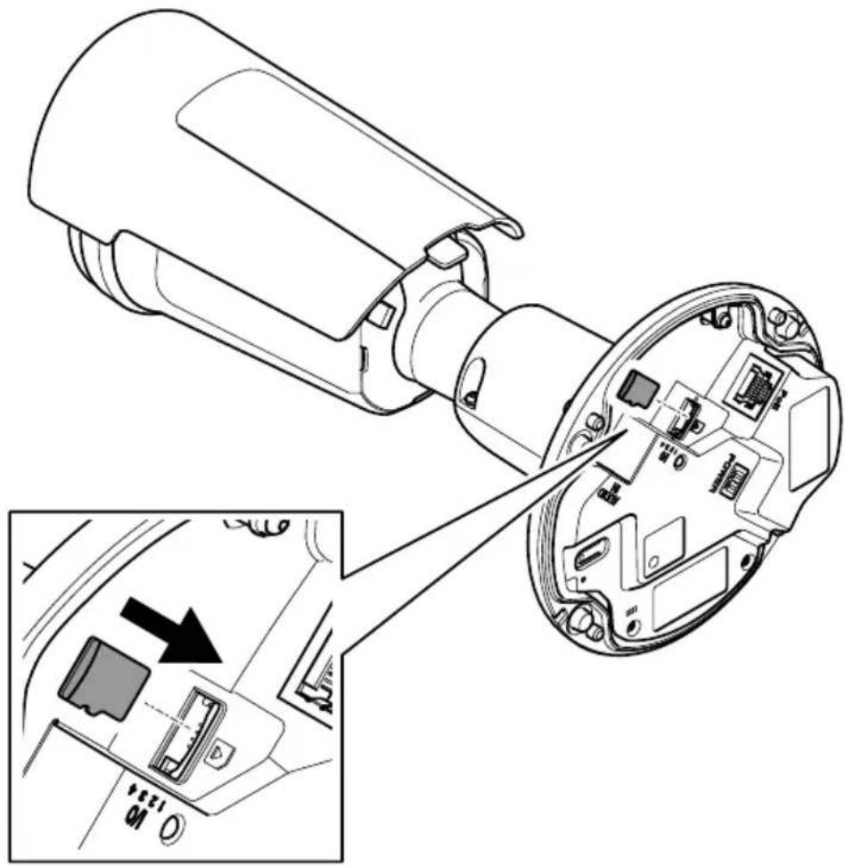
- You may only open the device to access the SD card and to connect the cables. Do not remove the device's front glass for any reason.
- Check all mounting fasteners for tightness at a regular interval.
- To maintain a smooth operation, clean the device regularly. Use water, mild detergent and damp cloth.
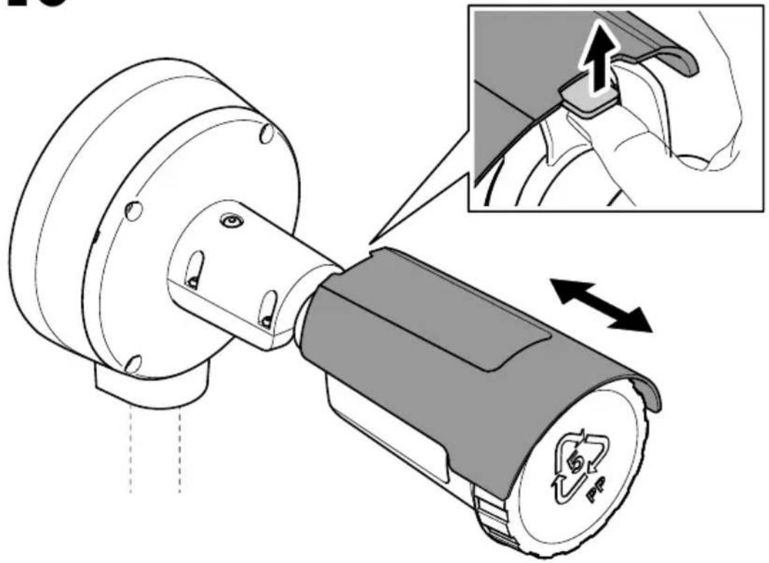
- Be careful not to scratch, damage or leave fingerprints on the front glass. This could decrease image quality. If possible, keep the protective plastic on the front glass until the installation is completed.
- Never use harsh detergents, gasoline, benzene, acetone, or similar chemicals.
Battery
Lithium coin cell 3.0 V batteries contain 1,2-dimethoxyethane; ethylene glycol dimethyl ether (EGDME), CAS no. 110-71-4.
Further information
- The user manual is available at axis.com
- To check if there is updated firmware available for your device, see axis.com/support
- For useful online trainings and webinars, see axis.com/academy
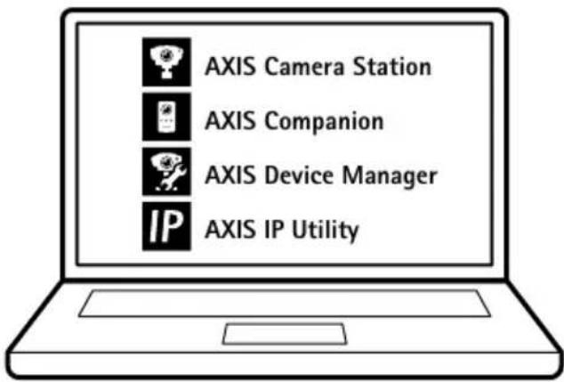
Optional accessories
For a complete list of available accessories for this product, go to the product's page on axis.com and select Software & Accessories.
flowchart
graph TD
    A[" gears shift"] --> B[" gear "]
    B --> C[" recycling "]
    C --> D[" final assembly with directional arrows"]
Câblage
AVERTISSEMENT
flowchart
graph TD
    A[" gears with rotational arrow"] --> B[" intermediate gear with internal components and recycling bin"]
    B --> C[" final gear with directional arrows indicating assembly"]
Verkabelung
WARNING
Cablaggio
AVVISO
natural_image
Mechanical component diagram showing a rotating shaft and housing with directional arrows (no text or symbols)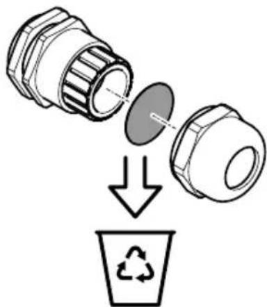
natural_image
Diagram showing a mechanical component being processed into a recycling bin (no text or symbols)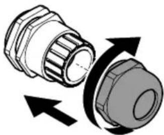
natural_image
Diagram of a mechanical component with directional arrows indicating rotation or movement (no text or symbols)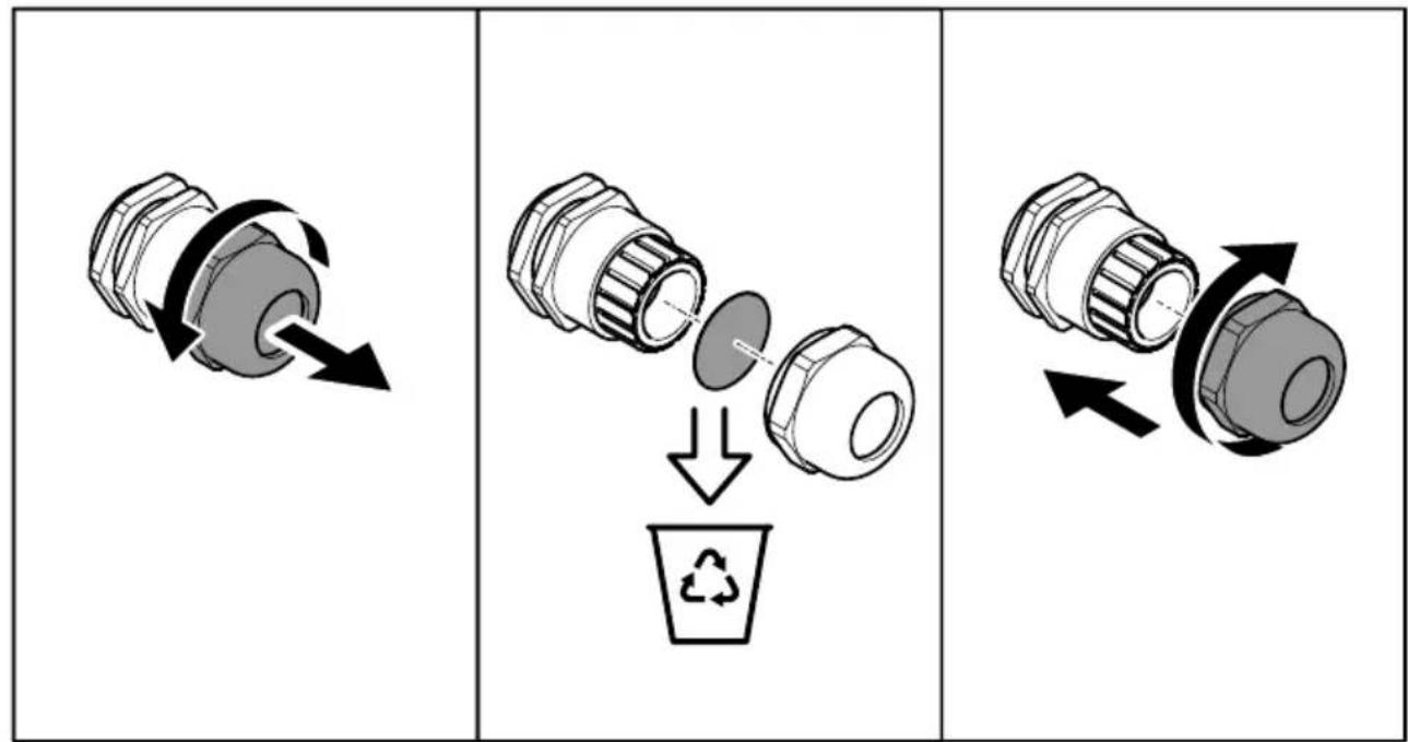
Cableado
ADVERTENCIA
接线
警告
natural_image
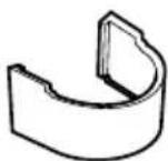
Technical line drawing of a mechanical component with no visible text or symbols1x
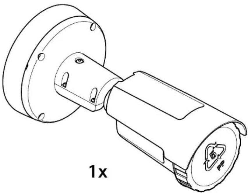
natural_image
Technical line drawing of a mechanical component with flange and housing, labeled '1x' (no text or symbols on the diagram itself)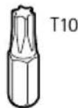
1x
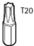
1x
1x
1x
1x
1x
1x
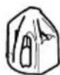
2x
microSD microSDHC microSDXC
natural_image
Technical diagram of a device's internal structure showing exploded view and close-up of internal components (no text or symbols)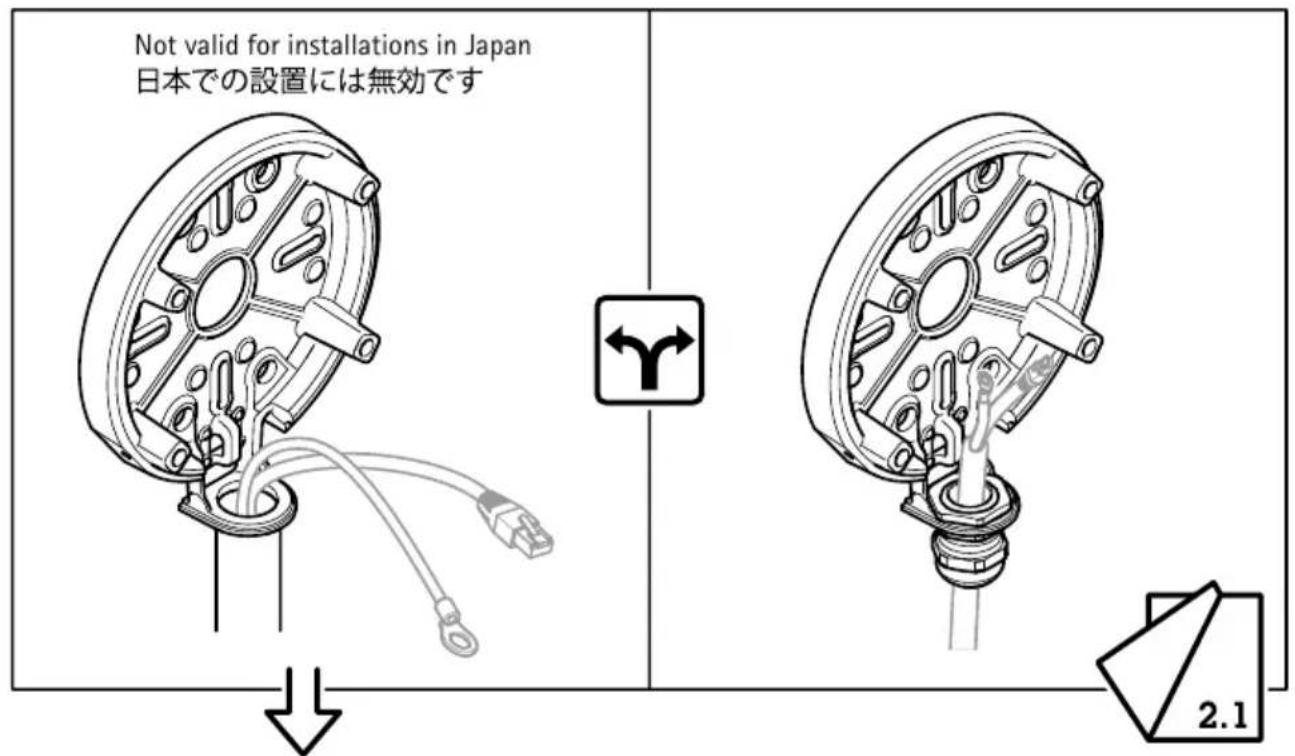
natural_image
Diagram of a mechanical component with wires and connectors, showing a rotating shaft and housing (no text or symbols)1.2
1.3
1.4
natural_image
Technical line drawing of a mechanical component with attached wiring and connectors (no text or symbols)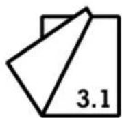
2.1
2.2
natural_image
Diagram showing two mechanical components with downward and upward arrows indicating movement or force (no text or symbols)2.3
2.4
2.5
2.6
3.2
3.3

12 V DC
3.4
3.5

3.6
3.7
!
3.8
3.9
3.10
natural_image
Technical illustration of a mechanical device with a magnified inset showing a hand adjusting the component (no text or symbols present)i
natural_image
Diagram of a mechanical component with arrows indicating motion or force direction (no text or symbols)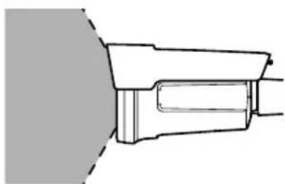
natural_image
Technical line drawing of a mechanical component or bracket (no text or symbols)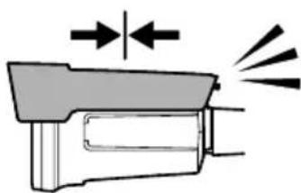
natural_image
Diagram of a mechanical component with arrows indicating motion or force direction (no text or symbols)
natural_image
Diagram of a mechanical component with a dashed light beam and internal structure (no text or symbols)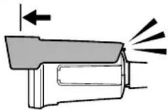
natural_image
Diagram of a mechanical component with arrows indicating motion or force direction (no text or symbols)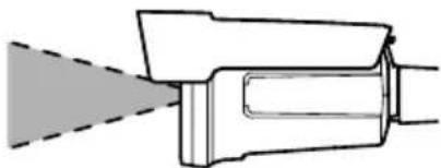
natural_image
Technical line drawing of a mechanical component with a dashed light beam (no text or symbols)3.11
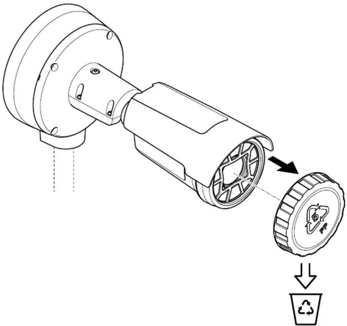
natural_image
Technical line drawing of a mechanical assembly with a pulley and disc, showing a recycling symbol (no text or labels)

3224768
2025-05 (M3.12)
© 2024 - 2025 Axis Communications AB