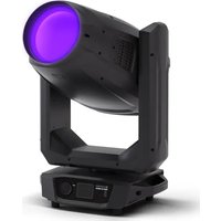
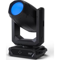
OPUS X4 PROFILE - Lamp Cameo - Free user manual and instructions
Find the device manual for free OPUS X4 PROFILE Cameo in PDF.


| Product type | Professional LED moving head |
| Brand | Cameo |
| Model | OPUS X4 PROFILE |
| Light source | LED 1 400 W, luminous flux 50 000 lm |
| Beam angle | 5.5° - 48° motorized |
| Color mixing | CMY + CTO, color temperature 6 000 K |
| Color wheels | 2 wheels: 1 with 6 colors + open, 1 with CTO/CTB and high CRI |
| Gobos | 2 gobo wheels, 6 gobos + open per wheel, rotation and indexing |
| Prism | 1 prism, 2 facets, rotating |
| Pan/tilt movement | Pan 0-270°, Tilt 0-540° or 630° (selectable) |
| Front lens diameter | 193 mm |
| Control protocols | DMX512, Art-Net, sACN, W-DMX™ (transmitter/receiver), RDM |
| DMX modes | 34, 41 and 56 channels |
| Power supply | 100-240 V AC, 50/60 Hz, power consumption 1 670 W |
| Fuse | T25AL/250V, externally replaceable |
| Connectors | PowerCON TRUE1 input, DMX 3 and 5 pin input/output, RJ45 network input/output, USB for update |
| Display | Backlit LCD touchscreen, glove compatible, battery powered |
| Cooling | Auto-controlled fan, modes Auto, Off, Constant Low/Mid/High |
| Dimensions (W x H x D) | 441 x 830 x 312 mm |
| Weight | 44.0 kg |
| Protection rating | IP20, for indoor use only |
| Operating temperature | 0 to 40 °C, humidity < 80% non-condensing |
| Minimum distance to illuminated surface | 5 m |
| Minimum distance to flammable materials | 0.5 m |
| Included accessories | 2 omega brackets, power cable, user manual |
| Maintenance and cleaning | Clean housing with damp cloth, dust air inlets, clean lenses regularly. Disconnect before maintenance. |
| Safety | Risk group RG2, do not stare at light source. Professional use only, not for household use. |
| Spare parts and repairability | Light sources not user-replaceable. Gobos replaceable by qualified personnel. Fuse user-replaceable. Repair by authorized technician. |
Frequently Asked Questions - OPUS X4 PROFILE Cameo
User questions about OPUS X4 PROFILE Cameo
0 question about this device. Answer the ones you know or ask your own.
Ask a new question about this device
Download the instructions for your Lamp in PDF format for free! Find your manual OPUS X4 PROFILE - Cameo and take your electronic device back in hand. On this page are published all the documents necessary for the use of your device. OPUS X4 PROFILE by Cameo.
USER MANUAL OPUS X4 PROFILE Cameo
natural_image
Black optical beam projector with purple light source, mounted on a base (no visible text or symbols)OPUS X4 PROFILE
LED PROFILE MOVING HEAD
CLOX4P
CONTENTS / INHALTSVERZEICHNIS / CONTENU /
CONTENIDO / TREŚĆ / CONTENUTO
ENGLISH
INFORMATION ON THIS USER MANUAL 6
INTENDED USE 6
EXPLANATIONS OF TERMS AND SYMBOLS 6
SAFETY INSTRUCTIONS 7
NOTES FOR PORTABLE INDOOR DEVICES 11
PACKAGING CONTENT 11
INTRODUCTION 11
CONNECTIONS AND OPERATING/DISPLAY ELEMENTS 12
OPERATION 15
SET-UP AND INSTALLATION 28
CARE, MAINTENANCE, AND REPAIR 30
REPLACING GOBOS 31
DIMENSIONS 33
TECHNICAL DATA 34
MINIMUM DISTANCE TO ILLUMINATED SURFACE 36
MINIMUM DISTANCE TO NORMALLY FLAMMABLE MATERIALS 36
DISPOSAL 36
MANUFACTURER'S DECLARATIONS 37
DEUTSCH
REPLACEMENT DES GOBOS 100
DIMENSIONS 102
CARACTÉRISTIQUES TECHNIQUES 103
DISTANCE MINIMALE PAR RAPPORT À LA SURFACE ÉCLAIRÉE 105
DISTANCE MINIMALE PAR RAPPORT AUX MATÉRIAUX INFLAMMABLES ORDINAIRES 105
MISE AU REBUT 105
DÉCLARATIONS DU FABRICANT 106
ESPAÑOL
This device has been developed and manufactured to the highest quality standards to ensure many years of trouble-free operation. Please read this user manual carefully to be able to quickly put your new Cameo Light product to optimum use. Further information about Cameo Light is available on our website: CAMEOLIGHT.COM
INFORMATION ON THIS USER MANUAL
- Carefully read the safety instructions and the entire manual before operating the device.
- Observe the warnings on the device and in the user manual.
• Always keep the user manual within reach. - If you sell or pass on the device, it is important that you also include this user manual, as it is an integral part of the product.
INTENDED USE
This product is a device for event technology!
This product has been developed for professional use in the field of event technology and is not suitable for use as domestic lighting!
Furthermore, this product is only intended for qualified users with specialist knowledge of event technology!
Temporary operation! Event equipment is generally designed for temporary use only and not for continuous operation and fixed installation!
Use of the product that is not in accordance with the specified technical data and operating conditions is considered improper use!
Liability is exempted when damage and third-party damage to persons and property is caused by inappropriate use!
The product is not suitable for:
- Persons (including children) with limited physical, sensory, or mental abilities or lack of experience and knowledge.
- Children (children must be instructed not to play with the device).
EXPLANATIONS OF TERMS AND SYMBOLS
- DANGER: The word DANGER, possibly in combination with a symbol, indicates immediately hazardous situations or conditions for life and limb.
- WARNING: The word WARNING, possibly in combination with a symbol, indicates potentially hazardous situations or conditions for life and limb.
- CAUTION: The word CAUTION, possibly in combination with a symbol, indicates situations or conditions that may lead to injury.
- ATTENTION: The word ATTENTION, possibly in combination with a symbol, indicates situations or conditions that may lead to damage to property and/or the environment.

This symbol identifies hazards that can cause electric shock.

This symbol indicates hazardous areas or hazardous situations.

This symbol indicates hazards caused by hot surfaces.
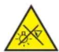
This symbol indicates that you must avoid looking or staring at the light source.

This symbol indicates a device in which there are no user-serviceable parts.

This symbol indicates additional information on the operation of the product.
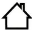
This symbol indicates a device that may only be used in dry rooms.
SAFETY INSTRUCTIONS
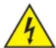
DANGER:
- Do not open the device, and do not make any modifications to it.
- If your device no longer functions properly, if liquids or objects get inside it, or if it has been damaged in any other way, switch it off immediately and disconnect it from the power supply. The device may be repaired only by authorised qualified personnel.
- For devices of protection class 1, the protective conductor must be connected correctly. Never disconnect the protective conductor. Devices of protection class 2 do not have a protective conductor.
- Ensure that live cables are not kinked or otherwise mechanically damaged.
- Never bypass the device fuse.
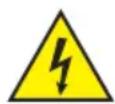
WARNING:
- The device may not be operated if it shows obvious signs of damage.
- The device may only be installed in a voltage-free state.
- If the device's mains cable is damaged, the device may not be operated.
- Permanently attached mains cables may only be replaced by a qualified person.
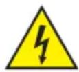
ATTENTION:
- Do not operate the device if it has been exposed to large temperature fluctuations (for example, after transport). Moisture and condensation may damage the device. Switch on the device only when it has reached ambient temperature.
- Make sure that the voltage and frequency of the mains correspond to the values specified on the device. If the device has a voltage selector switch, do not connect the device until it has been set correctly. Use only suitable mains cables.
- To disconnect the device from the mains at all poles, it is not sufficient to press the on/off switch on the device.
- Make sure that the fuse used corresponds to the type specified on the device.
- Make sure that appropriate measures have been taken against power surges (for example, lightning strike).
- Observe the specified maximum output current on devices with Power Out connection. Ensure that the total current consumption of all connected devices does not exceed the specified value.
- Replace plug-in mains cables only with original cables.

DANGER:
- Danger of suffocation/choking! Plastic bags and small parts must be kept out of reach of persons (including children) with reduced physical, sensory, or mental capabilities.
- Danger caused by falling device! Make sure that the device is securely installed and cannot fall down. Only use suitable stands or mounts (particularly for fixed installations). Ensure that accessories are properly installed and secured. Ensure that applicable safety regulations are observed.

WARNING:
- Use the device only in the prescribed manner.
- Operate the device only with the accessories recommended and intended by the manufacturer.
- During installation, observe the safety regulations applicable in your country.
- After connecting the device, check all cable routes to avoid damage or accidents, for example, due to tripping hazards.
- Always observe the specified minimum distance to normally flammable materials! Unless explicitly stated, the minimum distance is 0.3 m.
- Always observe the minimum distance to the illuminated surface specified on the device!

CAUTION:
- Moving components such as mounting brackets or other movable components may become jammed.
- Devices with motor-driven components may result in injury from the movement of the device. Sudden movement of the device can cause shock reactions.
- The exterior surface of the device can become very hot during regular operation. Ensure that accidental touching of the housing is not possible. Always allow the device to cool sufficiently before removal, maintenance work, charging, or similar.

ATTENTION:
- Do not install or operate the device in the vicinity of radiators, heat accumulators, furnaces, or other heat sources. Ensure that the device is always installed in such a way that it is sufficiently cooled and cannot overheat.
- Do not place ignition sources such as burning candles near the device.
- Ventilation openings must not be covered, and fans must not be blocked.
- Use the original packaging or packaging provided by the manufacturer for transport.
- Avoid shock or impact to the device.
- Observe the IP protection class, as well as the ambient conditions such as temperature and humidity according to the specification.
- Devices can be continuously further developed. In the event of deviating information on operating conditions, performance, or other device properties between the user manual and the device labelling, the information provided on the device always has priority.
- The device is not suitable for tropical climates and for operation at heights of 2,000 m above sea level or higher.
- Unless explicitly stated, the device is not suitable for operation in marine conditions.
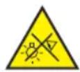
CAUTION! IMPORTANT INFORMATION ON LIGHTING PRODUCTS!
- This device is a risk group 2 device. Do not stare at the light source! Do not stare at the light beam! Do not look directly into the lamp with optical instruments such as magnifying glasses or binoculars!
- Stroboscopic effects may cause epileptic seizures in susceptible individuals!
- Permanently installed lamps are built into these lighting units. These may not be replaced by the user. The lamps contained in this lighting unit may only be replaced by the manufacturer, its service partner, or a similarly qualified person.



The quality and performance of wireless signal transmissions generally depends on the ambient conditions.
For example, the following factors can impact range and signal stability:
Shielding (for example, masonry, metal structures, water)
High volumes of radio traffic (for example, powerful wireless LAN networks) Interference
Electromagnetic radiation (for example, LED video screens, dimmers)
All range specifications refer to free-field line-of-sight applications without interference!
The operation of radio transmission systems is subject to official regulations. These may vary from region to region and must be checked by the operator before use (for example, radio frequency and transmission power).

WARNING: Devices with wireless signal transmission are not suitable for use in sensitive areas in which radio operation can lead to potentially detrimental interactions. These include:
- Hospitals, health centres, or other healthcare facilities that provide patient treatment with qualified personnel and equipment.
• Class I, II, and III hazardous areas - Restricted areas
- Military facilities
- Aircraft or vehicles
- Areas where the use of mobile phones is prohibited

TRANSMISSION VIA W-DMX
WARNING: In general, wireless DMX transmission must not be used for applications involving safety-related factors that might result in personal injury or property damage in the event of a failure.
This applies in particular to moving scene or truss structures, DMX-controlled motors/lifts or lifting devices for operating DMX-operated platform lifts, hydraulic systems or comparable moving components.
Furthermore, wireless DMX transmission must not be used to control flame or pyrotechnic devices, explosion-driven effects, or gas or liquid effects. These include CO_2 cannons, confetti shooters, water effects, or similar.

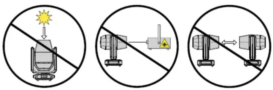
ATTENTION! POTENTIAL DAMAGE FROM EXTERNAL LIGHT SOURCES!
Solar radiation, laser radiation, and bundled light beams from other lights may damage the housing and internal components, such as filters, gobo and colour wheels, motors, cables, belts, as well as light sources!
Do not expose the device and especially the lens opening to direct sunlight, laser radiation, and bundled light beams from other lights during unpacking, installation, prolonged disuse, and operation! Always point the lens opening towards the floor when the device is not in use! Damage caused by external light sources is excluded from the manufacturer's warranty!

NOTES FOR PORTABLE INDOOR DEVICES
- Temporary operation! Event equipment is generally only designed for temporary operation.
- Continuous operation or permanent installation can impair the functionality of the device and cause premature ageing.
PACKAGING CONTENT
Remove the product from the packaging and remove all packaging material.
Please check the completeness and integrity of the delivery, and notify your distribution partner immediately after purchase if the delivery is not complete or if it is damaged.
The packaging content for the product includes:
▶ 1 × ORUSProfile Moving Head
▶ 1 × Mains cable
▶ 2 × Omega bracket
▶ User manual
INTRODUCTION
PROFESSIONAL LED PROFILE MOVING HEAD
CLOX4P
CONTROL FUNCTIONS:
34-, 41-, and 56-channel DMX control
Master/slave operation
Stand-alone operation
W-DMX ^TM
FEATURES:
1400 W LED. DMX512. W-DMX™. Art-Net and sACN. 5-pin DMX connections. 2× omega mounting bracket included. Operating voltage: 100–240 V AC.
The light supports the remote device management (RDM) standard. Remote device management allows the user to monitor the status and configuration of RDM devices using an RDM-capable controller, such as the optionally available Cameo UNICON (item number CLIREMOTE).
CONNECTIONS AND OPERATING/DISPLAY ELEMENTS
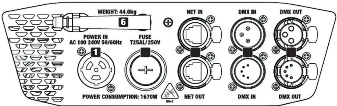
1 POWER IN
TRUE1-compatible mains input socket. Operating voltage 100–240 V AC / 50–60 Hz. A suitable mains cable with TRUE1-compatible plug is included in the packaging content.
2 FUSE
Fuse holder for 10 × 38 mm fuses. IMPORTANT NOTE: Only replace the fuse with a fuse of the same type and value. In the event of repeated fuse failure, please contact an authorised service centre.
3 DMX IN
Male 3-pin and 5-pin XLR sockets for connection of a DMX control device (such as a DMX console). Only use the ports alternatively.
4 DMX OUT
Female 3-pin or 5-pin XLR sockets for sending the DMX control signal. Only use the ports alternatively.
5 NET IN / OUT
RJ45 network connectors for connecting to an Art-Net or sACN network in order to send the control signal. Use CAT 5e or better cables to set up the network.
6 W-DMX™ ANTENNA
Antenna for W-DMX ^TM control.
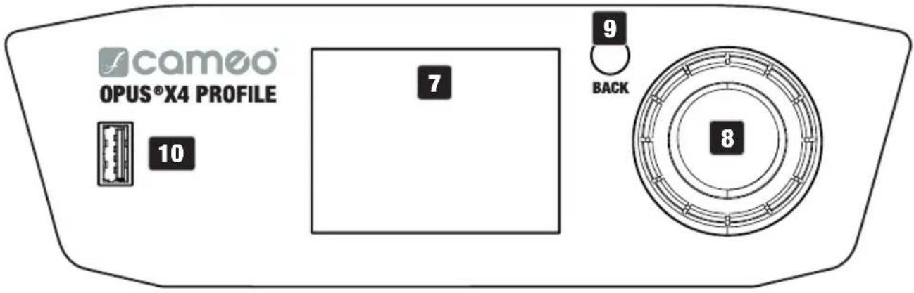
7 PRESSURE-SENSITIVE LC DISPLAY WITH ILLUMINATION
Thanks to the pressure-sensitive LC display, the device can be operated directly from the display (glove-compatible). The display shows the currently activated operating mode (main display), the menu items in the main menu and sub-menus, and the numerical value or status in specific menu items. If there is no control signal to the device, the display starts flashing; the flashing stops as soon as a control signal is available (W-DMX, DMX and slave operation, Art-Net and sACN).
8 ROTARY-PUSH ENCODER
Rotary-push encoder for navigating in the editing menu, adjusting system settings, and changing values and status in the corresponding menu items.
Starting from the main display, press the encoder to enter the main menu. Select the individual menu items in the main menu (such as Control, Settings, Info) and in the sub-menus by turning the encoder and confirm the selection by pressing the encoder. Change the value or status in a menu item by turning the encoder and confirm the change by pressing the encoder.
9 BACK
Briefly press BACK to go up one level in the menu structure. To go directly from the sub-menus to the main display, press and hold the BACK button for about 2 seconds.
10 USB INTERFACE
USB interface for updating the device firmware. In the “Service” menu, set the status for “USB update” to “Yes”. When available, download the latest firmware from the product page at www.cameolight.com, unzip it, and copy the files to a folder without special characters on a USB stick. Disconnect the moving head from the mains and all input connections (DMX/Ethernet), connect the USB stick to the USB interface, and reconnect the moving head to the mains. The USB stick is automatically recognised and shown in the display. Now navigate to the corresponding folder on the USB stick and click “ON” to confirm. The update procedure begins. If updates are required for several components, the procedure must be carried out individually for all updates. Do not remove the USB stick or disconnect the moving head from the mains during the update procedure.

BATTERY-POWERED DISPLAY
The battery-powered display can be activated even if the device is disconnected from the mains. To do this, press and hold the rotary-push encoder for approximately 2 seconds. You can now access device information and change and save system settings without mains connection. External control of the light is not activated in this case. For this reason, the display shows that there is no DMX signal even if a DMX signal is available at the device.
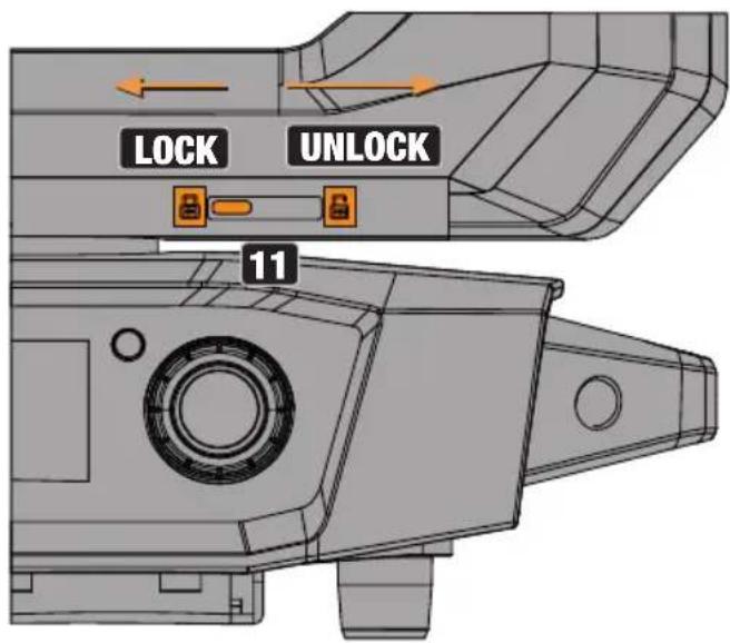
11 PAN LOCK
Mechanical locking device used to prevent rotation of the head in the horizontal direction during transport (eight possible locking positions). Disconnect the unit from the mains and slide the locking lever towards the pan rotation axis, moving the head of the unit horizontally until one of the eight locking positions is found and the locking lever engages (LOCK). Unlock the locking device before device start-up (UNLOCK).
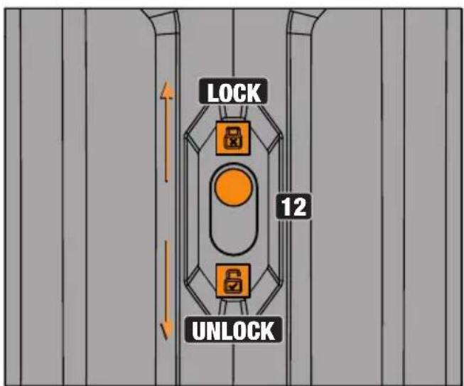
12 TILT LOCK
Mechanical locking device used to prevent rotation of the head in the vertical direction during transport (seven possible locking positions). Disconnect the unit from the mains and slide the locking lever towards the tilt rotation axis, moving the head of the unit vertically until one of the seven locking positions is found and the locking lever engages (LOCK). Unlock the locking device before device start-up (UNLOCK).
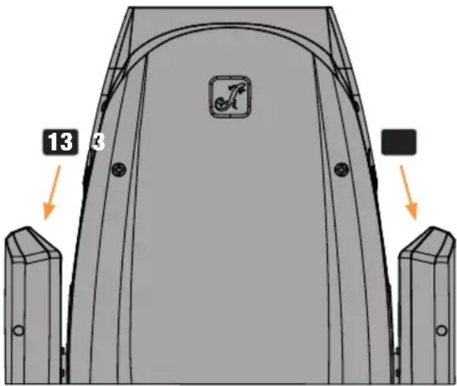
13 RECESSED GRIPS
In addition to the two transport handles on the base of the unit, there are convenient recessed grips at the top of the inner sides of the two device arms.
OPERATION
PLEASE NOTE
When the light is correctly connected to the mains, the Cameo logo is shown on the display during start-up and motor reset along with details of the device model. After this process, the light is ready for operation, and the previously activated operating mode is launched.
The main display is deactivated automatically after approximately two minutes of no input. Press BACK to go up one level in the sub-menus.
In the event of a technical fault, the warning triangle symbol appears in the top right-hand corner (tap for further information).
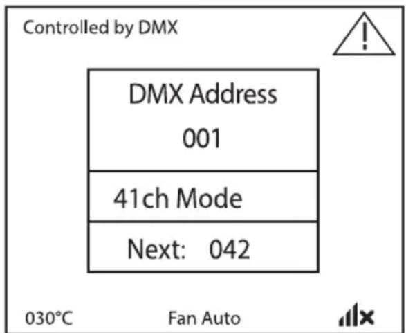
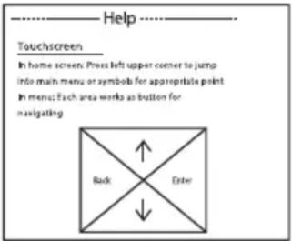
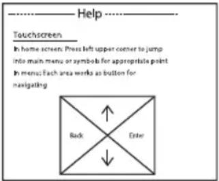
The light is operated firstly by means of the rotary-push encoder and the BACK button next to the display, and secondly the pressure-sensitive display (glove-compatible) itself can be used to access all menu items and configure settings intuitively as desired. The control panels in the main display and in the main menu or sub-menus and their functions are shown in the illustrations below. The fields marked grey in the illustration of the main display are control panels with direct access.
MAIN DISPLAY MAIN MENU AND SUB-MENUS
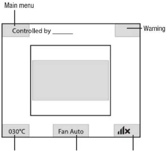
Temperature display Fan mode W-DMX settings
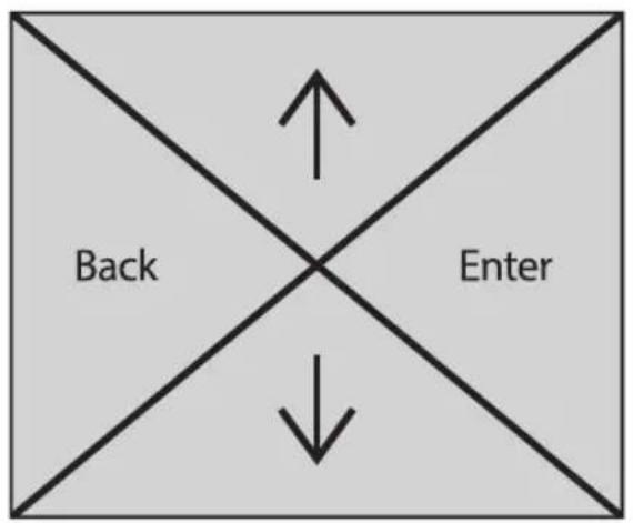
flowchart
graph TD
    A["Back"] --> B["Enter"]
    B --> A
    C["Down"] --> B
Information on the main display in the operating modes with external control: In the event that the control signal is interrupted, the characters in the centre of the display begin flashing; once the control signal is present again, the flashing stops.
Error message: If the warning symbol (triangle with exclamation mark) appears in the display, there is an error in one or more of the device's components. Which components are affected can be seen in the System Info Menu under Error Info. If a restart or reset does not rectify the error, please contact an authorised service centre.
W-DMX™
To pair a W-DMX receiver with a W-DMX-compatible transmitter, the reset command must be executed in the menu item "WDMX" under "Receiver" (select and confirm reset). The receiver is now in pairing standby and waiting for a pairing request from a transmitter. Start the pairing by selecting "Link" in the menu of the transmitter and confirming; the pairing now takes place automatically. In the same way, several receivers can be paired simultaneously or one after the other to a transmitter (such as for master/slave operation). A W-DMX connection is always maintained until the connection is disconnected by means of the reset command in the receiver or the unlink command in the transmitter, regardless of whether a device has been disconnected from the power supply in the meantime.
W-DMX™ STATUS
 | 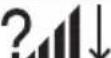 |  | 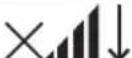 |  |  |
| W-DMX deactivated | W-DMX activated as receiver; not paired | W-DMX activated as receiver and paired; transmit-ter switched off or out of range | W-DMX activated as receiver and paired; no DMX signal | W-DMX activated as receiver and paired; DMX signal present | W-DMX activated as transmitter with G3 standard; DMX signal available |
The following is a description of how to operate the light using the rotary-push encoder and the BACK button next to the display.
CONTROL MENU (Control)
The control menu is used to select the various operating modes and set their options in the respective sub-menus.
SETTING THE DMX START ADDRESS (DMX Address)
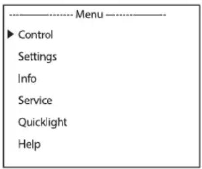
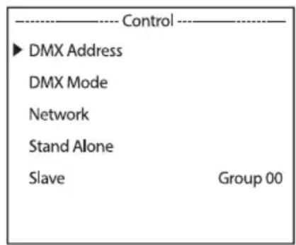
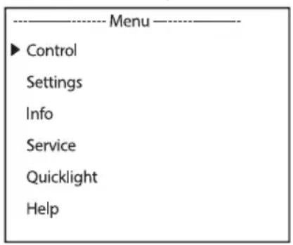
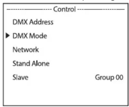
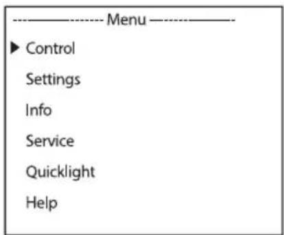
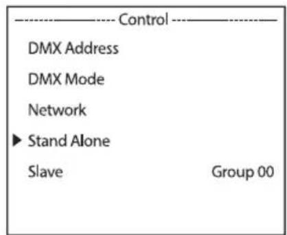
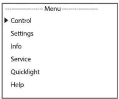
Starting from the main display, press the rotary-push encoder to enter the main menu. Select Control by turning the encoder and press the encoder to confirm. Now select DMX Address, confirm the selection, and then set the desired DMX start address. Confirm the setting.
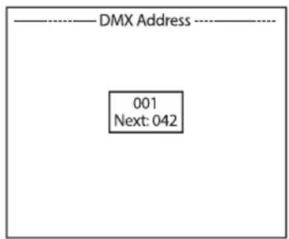
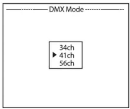
SETTING THE DMX OPERATING MODE (DMX Mode)
Starting from the main display, press the rotary-push encoder to enter the main menu. Select Control by turning the encoder and press the encoder to confirm. Now select DMX Mode, confirm the selection, and then select the desired DMX operating mode. Confirm the selection.
NETWORK SETTINGS (Network)
Starting from the main display, press the rotary-push encoder to enter the main menu. Select Control by turning the encoder and press the encoder to confirm. Now select the Network menu item and confirm again.
| ----Menu---- | |
| ▶ Control | |
| Settings | |
| Info | |
| Service | |
| Quicklight | |
| Help |
| Control | |
| DMX Address | |
| DMX Mode | |
| Network | |
| Stand Alone | |
| Slave | Group 00 |
| Network | |
| Protocol | |
| Universe | |
| IP Address | |
| Subnet Mask | |
| Signal Routing |
Information on the sub-menu items in the “Network” menu and the corresponding setting options can be found in the table below (select by turning the encoder, confirm by pressing the encoder, change value or status by turning, confirm by pressing).
| Art-Net network | |||
| Protocol | Artnet | Control via Art-Net | |
| sACN | Control via sACN | ||
| Universe | Absolute Univ. | Setting of the absolute Art-Net universe | Dependent on net, subnet, and universe |
| Net | Setting of the Art-Net network | Depending on absolute universe | |
| Subnet | Setting of the Art-Net subnet | ||
| Universe | Setting of the Art-Net universe | ||
| IP Address | xxx.xxx.xxx.xxx | Setting of the IP address: Select block, confirm, set value, confirm | |
| Subnet Mask | xxx.xxx.xxx.xxx | Setting of the subnet mask: Select block, confirm, set value, confirm | |
| Signal Routing | Send to XLR | Relaying of the control signal to XLR Out | |
| Backup by XLR | Control via XLR with network signal interruption | ||
| Receive only | No connection between network signal and XLR connectors | ||
| sACN network | ||
| Protocol | Artnet | Control via Art-Net |
| sACN | Control via sACN | |
| Universe | Universe | Setting of the sACN universe |
| IP Address | xxx.xxx.xxx.xxx | Setting of the IP address: Select block, confirm, set value, confirm |
| Subnet Mask | xxx.xxx.xxx.xxx | Setting of the subnet mask: Select block, confirm, set value, confirm |
| Signal Routing | Send to XLR | Relaying of the control signal to XLR Out |
| Backup by XLR | Control via XLR with network signal interruption | |
| Receive only | No connection between network signal and XLR connectors | |
STAND-ALONE MENU (Stand Alone)
In the stand-alone operating modes “Play Scene” and “Play Loop”, the control signal of the corresponding operating mode can be output to slave units via XLR (Master/Alone -> Master). If you do not want to output the control signal, deactivate the output (Master/Alone -> Alone).
Activate one of the eight available scenes (Scene 1–8) or one of the eight available loops (Loop 1–8). The scenes and loops are pre-programmed, but can be customised (Edit Scene/Edit Loop).
Starting from the main display, press the encoder to enter the main menu. Select Control by turning the encoder and press the encoder to confirm. Now select Stand Alone and confirm again.
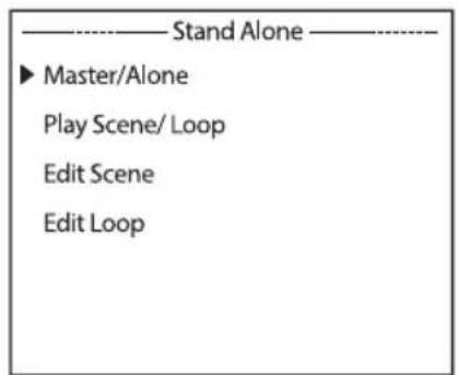
Information on the sub-menu items in the “Stand-alone” menu and the corresponding setting options can be found in the table below (select by turning the encoder, confirm by pressing the encoder, change value or status by turning, confirm by pressing).
| Stand Alone | ||||
| Master/Alone | Master | Control signal is relayed via DMX OUT | ||
| Delay Time | Off / 0.1s - 2.0s | Setting of a DMX delay for slave units | ||
| Alone | Control signal is not relayed | |||
| Play Scene/ Loop | Scene | Scene 1 - 8 | Selection and activation of the desired scene | |
| Loop | Loop 1 - 8 | Selection and activation of the desired loop | ||
| Edit Scene | Scene 1 - 8 | Pan | Set each scene individually. Scenes are activated by selecting them. | |
| Tilt | ||||
| Dimmer | ||||
| ... | ||||
| Edit Loop | Loop 1 - 8 | Step | 1 - 8 | Selection of Step 1-8 |
| t-Step | 0s - 20min | Setting of the step time | ||
| t-Fade | 0s - 20 min | Setting of the fade time | ||
| Step 1 + 2: Scene | 1 - 8 | Selection of Scene 1-8 | ||
| Step 3 - 8: Scene | 1 - 8 / Skip Step | Select Scene 1-8 or skip step | ||
SLAVE MODE
Standard slave mode: Starting from the main screen, press the encoder to enter the main menu. Select Control by turning the encoder and press the encoder to confirm. Now select Slave and confirm, then select slave group 0 (Group 00) and confirm again. Connect the slave and master units (same model, same software version) using a DMX cable or via wireless DMX and activate one of the stand-alone operating modes (Play Scene/Loop) in the master unit. The slave unit will now follow the master unit.
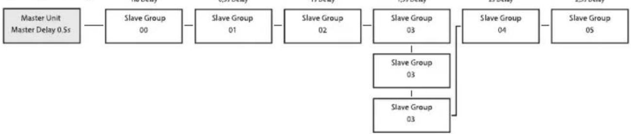
Extended slave mode: If you wish to control the slave units in master/slave mode using the stand-alone operating mode Play Loop, the control signal can be played back with a time delay of up to 24 steps. The delay is set in the Stand Alone menu Master/Alone -> Master in the master unit; the delay factor is set in the slave menu of the corresponding fixture (Group). This is a simple way to create a running light effect with a large number of identical lights that are running the same software version, which would otherwise require a suitable DMX controller and extensive programming. Connect the slave and master units (same model, same software version) using a DMX cable or via wireless DMX.
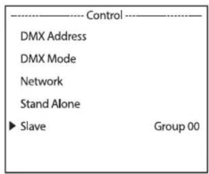
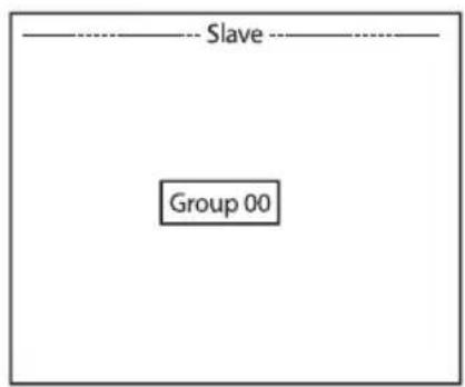
Assign the lights to one of up to 24 groups (plus Group 0) according to preference, whereby several lights can be assigned to one group. The group number is also the factor by which the delay time set in the master unit is multiplied.
Set-up example:
flowchart
graph LR
    A["Master Unit\nMaster Delay 0.5s"] --> B["Slave Group\n00"]
    B --> C["Slave Group\n01"]
    C --> D["Slave Group\n02"]
    D --> E["Slave Group\n03"]
    E --> F["Slave Group\n03"]
    E --> G["Slave Group\n03"]
    F --> H["Slave Group\n04"]
    H --> I["Slave Group\n05"]
SYSTEM SETTINGS (Settings)
Starting from the main display, press the encoder to enter the main menu. Select Settings by turning the encoder and press the encoder to confirm.
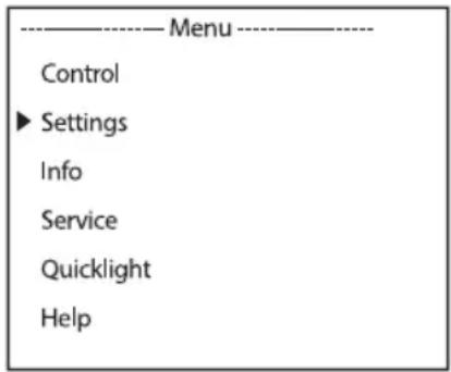
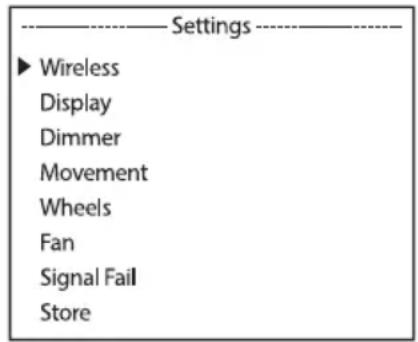
This will take you to the sub-menu for setting the sub-menu items (see table, select by turning the encoder, confirm by pressing the encoder, change value or status by turning, confirm by pressing).
| Settings (Bold print = factory setting) | ||||||||
| Wireless | Wireless settings | State | On | Wireless module activated | ||||
| Off | Wireless module deactivated | |||||||
| Operation Mode | Receive | Wireless module = receiver | ||||||
| TX CRMX | Wireless module = transmitter with CRMX transmitter standard | |||||||
| TX G4s | Wireless module = transmitter with G4s transmitter standard | |||||||
| TX G3 | Wireless module = transmitter with G3 transmitter standard | |||||||
| Linking | Receive Receiver: Reset the receiver and make it ready for pairing | |||||||
| Link | Transmitter: Pairing with compatible, ready-to-pair wireless devices | |||||||
| Linking | Unlink | Transmitter: Disconnect wireless DMX connections | ||||||
| Linking Key | Linking Key | Setting of the connection key | ||||||
| CRMX Mode (only available when in operating mode = receive) | CRMX | Receiver standard = CRMX | ||||||
| CRMX2 | Receiver standard = CRMX2 | |||||||
| CRMX Universe | A - H | Selection of CRMX universe A to H | ||||||
| Wireless | Wireless settings | Universe Metadata | RGB Color Code | Red, Orange, Yellow, Green, Cyan, Blue, Purple, White | RGB code for colour display of the universe | |||
| Universe A 16 Name | character string with a customisable name that identifies the universe | |||||||
| Bluetooth | On | Bluetooth switched on | ||||||
| Off | Bluetooth switched off | |||||||
| Pin | On | PIN request switched on (factory setting 081569) | ||||||
| Off | PIN request switched off | |||||||
| Signal Routing | Send to XLR | Relaying of the control signal to XLR (DMX OUT) | ||||||
| Backup by Control via XLR (DMX IN) with wireless signal interruption | ||||||||
| Receive only | No connection between wireless DMX signal and XLR connectors | |||||||
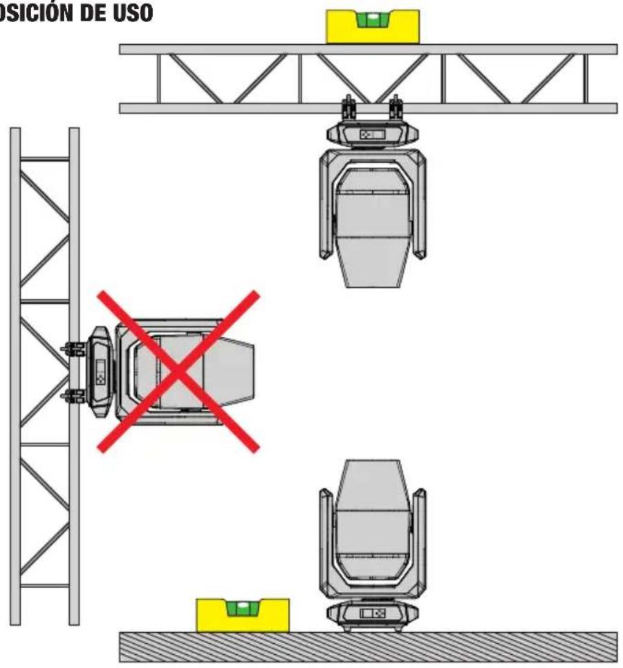
| Display | Display settings | Reverse | On | 180° display rotation (for example, for overhead installation) | ||||
| Off | No display rotation | |||||||
| Auto | Automatic position detection (upright/overhead mounting) | |||||||
| Off Timer | None | Permanently on | ||||||
| 20s | Deactivation after approximately 20 seconds of inactivity | |||||||
| Dimmer | Dimmer settings | Curve | Linear | Light intensity increases linearly with DMX value | ||||
| Exponential | Light intensity can be finely adjusted at lower DMX values and broadly adjusted at higher DMX values | |||||||
| Logarithmic | Light intensity can be broadly adjusted at lower DMX values and finely adjusted at higher DMX values | |||||||
| S-Curve | Light intensity can be finely adjusted at lower and higher DMX values and broadly adjusted at medium DMX values | |||||||
| Dimmer | Dimmer settings | PWM Frequency | 650Hz, 1530Hz, 3600Hz, 12kHz, 18.9kHz, 25kHz | Selection of LED PWM frequency | ||||
| Response | LED | The light responds immediately to changes of the DMX value | ||||||
| Halogen | The light behaves in a similar way to a halogen light with gradual changes of brightness | |||||||
| Movement | Head movements settings | Pan Reverse | On | Pan direction reversed | ||||
| Off | Pan direction not reversed | |||||||
| Tilt Reverse | On | Tilt direction reversed | ||||||
| Off | Tilt direction not reversed | |||||||
| Pan Angle | 630° | Pan angle 630° | ||||||
| 540° | Pan angle 540° | |||||||
| Position Automatic position correction enabled | ||||||||
| Feedback | Off | Automatic position correction disabled | ||||||
| Move in Black on during head movement | ||||||||
| Off | No blackout during head movement | |||||||
| Silent Movement | On | Slowed motor movements for quieter operation | ||||||
| Off | Function deactivated | |||||||
| Reset Mode | Fast | The procedure for resetting movements is carried out with a reduced movement range in combination with calibration values. This makes faster and more subtle resetting movements possible. | ||||||
| Normal | The procedure for resetting movements is carried out over the entire movement range | |||||||
| Wheels | Gobo and colour wheel settings | Gobo Wheel | Position | Clock-wise | Gobo wheel always rotates clockwise | |||
| Short | Gobo wheel rotates the short-est distance | |||||||
| Movement | Snap | Gobo wheel jumps directly back to the desired gobo when the relevant value is reached | ||||||
| Scroll | Continuous rotation of the gobo wheels | |||||||
| Wheels | Gobo and colour wheel settings | Gobo Wheel | Colour Correction | On | Colour shift compensation is activated during gobo use | |||
| Off | Function deactivated | |||||||
| Color Wheel | Position | Clock-wise | Gobo wheel always rotates clockwise | |||||
| Short | Gobo wheel rotates the short-est distance | |||||||
| Movement | Snap | Colour wheel jumps directly back to the desired colour filter when the relevant value is reached | ||||||
| Scroll | Continuous rotation of the colour wheel | |||||||
| Move in Black on in the event of value changes in the colour and gobo wheels | ||||||||
| Framing L & R Control | (Left & Right) | Standard function: The xA channel of the blade controls the left side of the blade x and the xB channel controls the right side | ||||||
| P & A (Posi-tion & Angle) | Alternative control of the aperture sliders: The xA channel of the blade controls the insertion of the blade x and the xB channel controls the angle of the blade | |||||||
| Fan | Fan setting | Auto | Automatic fan control | |||||
| Off | Deactivated fan with greatly reduced brightness | |||||||
| Constant Low | Constant low fan speed with reduced brightness, if necessary | |||||||
| Constant Mid | Constant average fan speed with reduced brightness, if necessary | |||||||
| Constant High | Constant high fan speed | |||||||
| Signal Fail | Operational status with DMX signal fault | Hold | Last command is retained | |||||
| Last Stand Alone | The last selected stand-alone operating mode is activated | |||||||
| Fade to Black (10s) | 10-second fade to blackout | |||||||
| Blackout | Activates blackout | |||||||
| Full | Full on | |||||||
| Store | Save settings in three custom presets | User A | Save all current settings as user preset A | |||||
| User B | Save all current settings as user preset B | |||||||
| User C | Save all current settings as user preset C | |||||||
SYSTEM INFORMATION (Info)
Starting from the main display, press the encoder to enter the main menu. Select Info by turning the encoder and press the encoder to confirm.
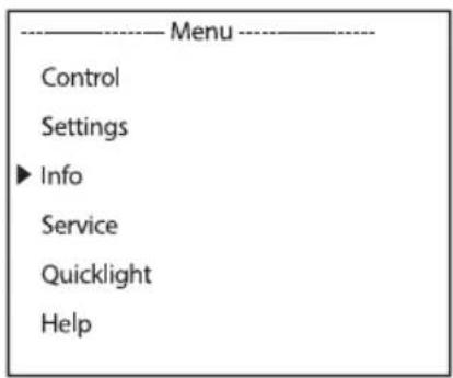
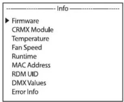
Information on the sub-menu items in the "Info" menu and the corresponding options can be found in the table below (select by turning the encoder, confirm by pressing the encoder).
| Info | |||
| Firmware | DISP: | Vx.x.x | Display of the firmware version of the corresponding component |
| NET: | Vx.x.x | ||
| DIMMER: | Vx.x.x | ||
| ... | Vx.x.x | Display of the firmware version of the corresponding component | |
| CRMX Module | Module installed | TimoTwo | Wireless module model |
| Device Name | OPUSX4P | Device name | |
| Version | HW (Hardware) SW (Software) | Hardware version number Software version number | |
| Link Quality | % | Connection quality in per cent | |
| Data Source | None / DMX / Wireless Link / SPI / BLE | Information on the data source | |
| Status | Operational: DMX Data: RDM Identify: RF Link: Link State: | Status information | |
| Temperature | LED | xxx °C/°F | Display of the temperature of the corresponding component |
| Base | xxx °C/°F | ||
| Temperature Unit | °C | Setting of the temperature unit (press ENTER to change) | |
| °F | |||
| Fan Speed | xxxx RPM | Display of the speed of the corresponding fan | |
| Runtime | Total | xxxx h : xx m | Total operating time |
| Operation | xxxx h : xx m | Time in use | |
| LED | xxxx h : xx m | Lamp operating time | |
| Service | xxxx h : xx m | Operating time since the last reset of the service operating time | |
| MAC Address | xx:xx:xx:xx:xx:xx | MAC address | |
| RDM UID | RDM unique identifier | ||
| DMX Values | Display of the DMX values present | ||
| Error Info | Error display in case of malfunction | ||
| DMX Table | Display of DMX mode tables | ||
SERVICE MENU (Service)
Starting from the main display, press the encoder to enter the main menu. Select Service by turning the encoder and press the encoder to confirm.
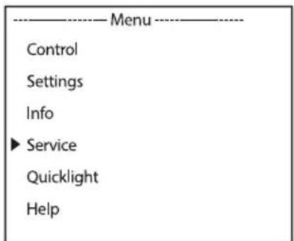
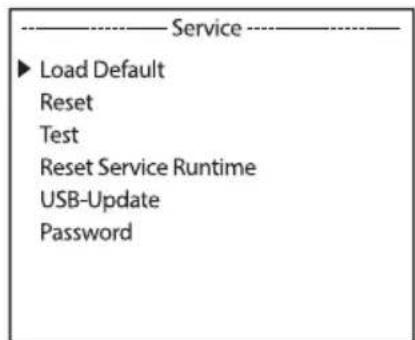
Information on the sub-menu items in the “Service” menu and the corresponding options can be found in the table below (select by turning the encoder, confirm by pressing the encoder, change value or status by turning, confirm by pressing).
| Service | ||
| Load Default | Factory Default | Reset to factory setting |
| User A | Reset to user A values(save user values: Settings -> Store) | |
| User B | Reset to user B values(save user values: Settings -> Store) | |
| User C | Reset to user C values(save user values: Settings -> Store) | |
| Reset | Pan/Tilt | Reset pan/tilt motors |
| Head | Reset motors in the device head | |
| All | Reset all motors | |
| Test | Test Sequence | Pre-programmed sequence to test all components |
| Stress Test | Pre-programmed sequence to test all components under maximum load | |
| Motor Test | Activate all motors individually with values of 000 to 255 | |
| Reset Service Runtime | No | Do not reset service operation time |
| Yes | Reset service operating time | |
| USB Update | No | Do not run firmware update via USB interface |
| Yes | Run firmware update via USB interface | |
| Password | For service purposes only | |
QUICKLIGHT
Set up a scene quickly and easily using the basic moving head functions without an external controller. Starting from the main display, press the encoder to enter the main menu. Select Quick-light by turning the encoder and press the encoder to confirm. Select a menu item, confirm, and set the desired value. Confirm each value change.
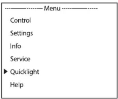
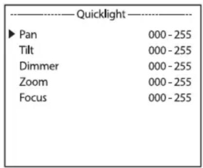
If the Quicklight operating mode is activated, the display does not automatically change to the main display; when leaving the Quicklight menu, Quicklight operating mode is automatically terminated. The settings in the Quicklight menu are retained until the next restart of the light; as a result, Quicklight can be accessed repeatedly with the same settings as long as the fixture remains switched on. After a restart, the values are reset to the Quicklight settings.
HELP (Help menu)
On three pages in the help menu, you will find: (1) information on quick commands that take you directly to specific menu items; (2) information on the division of the display into control panels in the main menu and the sub-menus; and (3) information on the device itself. Starting from the main display, press the encoder to enter the main menu. Select Help by turning the encoder and press the encoder to confirm. Now select the desired information again by turning the encoder.
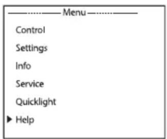
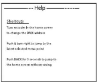
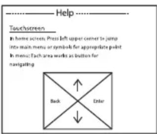

| ShortcutsMain display: The DMX start address can be changed directly by turning the encoderPress the encoder and turn it to the right to go to the last selected menu itemPress BACK for 3 seconds to return to the main display without saving | TouchscreenMain display: Press the top left corner to access the main menu or the icons for the corresponding menu itemIn the menu: Each area functions as a button for navigation |
SET-UP AND INSTALLATION

DANGER: Overhead mounting requires extensive experience, including the calculation of the load limit values of the installation material and regular safety inspection of all installation materials and fixtures. If you do not have these qualifications, do not attempt to perform installation yourself. Refer instead to a qualified professional. There is a risk that devices that are incorrectly installed and secured may come loose and fall down. This can cause serious injury or death.
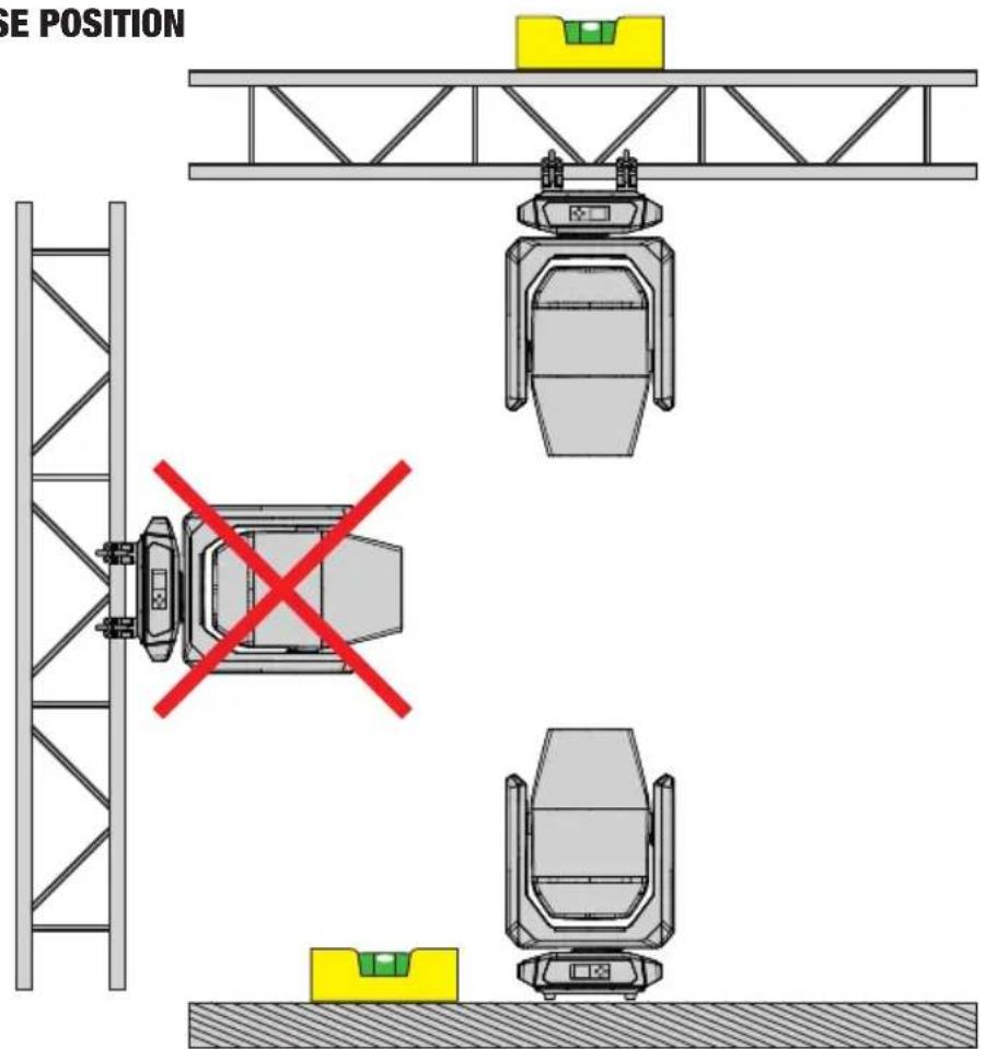
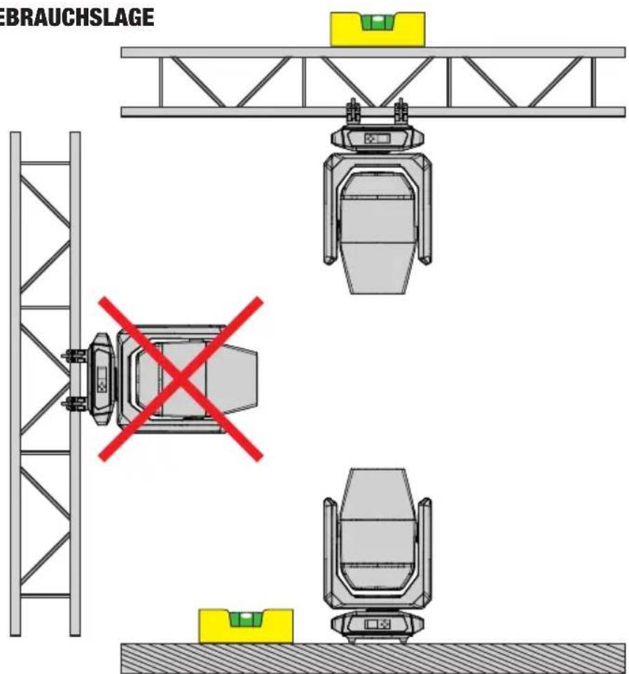
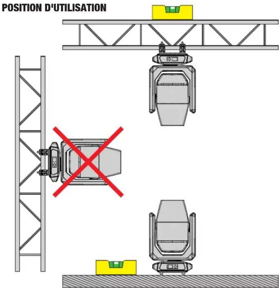
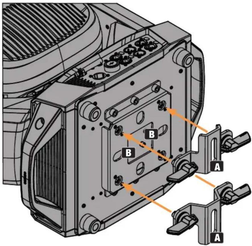
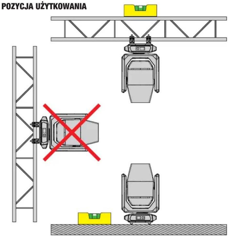
Thanks to its integrated rubber feet, the light can be positioned in a suitable location on a level surface. It can be truss-mounted using two omega brackets, which are attached to the base of the device (III. 1-A). If required, the two omega brackets can also be mounted on the appliance base rotated by 90^ (III. 2-A). Two omega brackets are included in the packaging content. Suitable truss clamps are available as an option. Ensure firm connections, and secure the light to the securing lug (B) with a suitable safety cable.
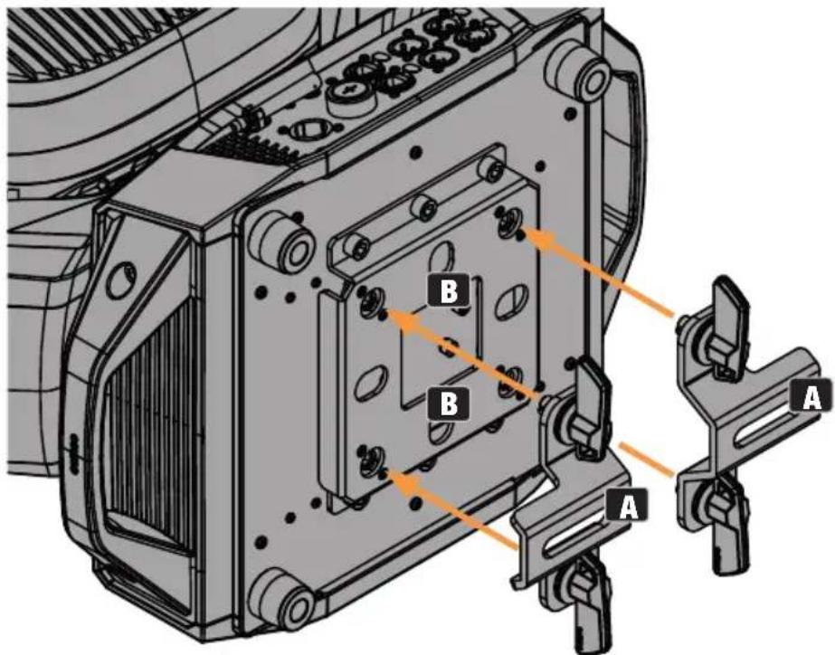
Illustration 1
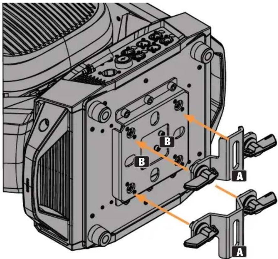
Illustration 2

USE POSITION
CARE, MAINTENANCE, AND REPAIR
In order to ensure the long-term, proper functioning of the device, it must be regularly cleaned and, if necessary, serviced. The care and maintenance required depends on the intensity of use and the environment in which it is used. We recommend a visual inspection before each operation. Furthermore, we recommend carrying out all the applicable service measures specified below once every 500 operating hours or, in the case of a lower intensity of use, at the latest after one year. Warranty claims may be limited should defects result from inadequate service and maintenance.

WARNING! Before carrying out any care or maintenance, the power supply – and, if possible, all device connections – must be disconnected.
NOTE! Improper care can lead to impairment or even destruction of the device.
- Housing surfaces must be cleaned with a clean, damp cloth. Make sure that no moisture can penetrate the device.
- Air inlets and outlets must be regularly cleaned of dust and dirt. If compressed air is used, make sure that damage to the device is prevented (for example, fans must be blocked in this case, as they could otherwise over-rev).
- Cables and connectors must be cleaned regularly, and dust and dirt must be removed.
- In general, no cleaning agents or abrasive agents may be used; otherwise, the surface finish may be damaged.
- Devices must be stored in a dry environment and protected from dust and dirt.
- To ensure correct and safe operation, all accessible or removable lenses and light-emitting apertures must be cleaned regularly.
MAINTENANCE AND REPAIR (by qualified personnel only)

DANGER! There are live components in the device. Even after disconnecting from the mains, there may still be residual voltage in the device, for example, due to charged capacitors.
PLEASE NOTE! Maintenance and repair work may only be carried out by sufficiently qualified personnel. If in doubt, consult a specialist workshop.
PLEASE NOTE! Improperly performed maintenance work may affect warranty claims.
PLEASE NOTE! For conversion or retrofit sets provided by the manufacturer, it is essential to observe the enclosed installation instructions.
REPLACING GOBOS

ATTENTION:
Gobos may only be replaced by qualified personnel. If you are not qualified to do this, do not try to replace gobos yourself. Refer instead to professional companies.
When carrying out any work, make sure that no foreign bodies enter the housing!
When replacing the gobos, make sure that the gobos are inserted correctly into the corresponding gobo holder. Otherwise, heat damage to the gobos and gobo holders may occur!
- Disconnect all poles of the device from the power supply (pull out the mains plug). Now lock the light head (pan and tilt lock).
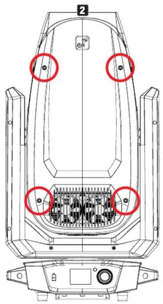
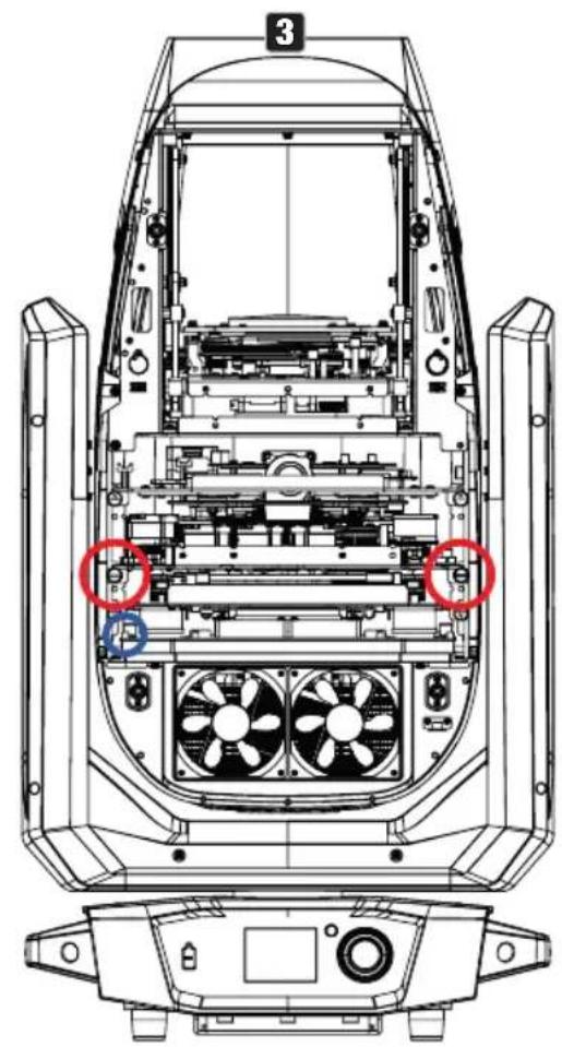
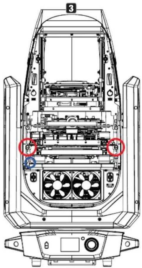
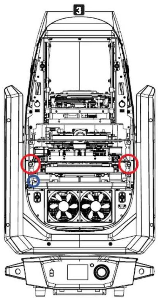
- Release the four locks on the cover of the device head on the side opposite the PAN LOCK (see markings in the illustration, bayonet lock with cross-slotted head, 1/4 turn to the left). Loosen the cover from the light head, loosen the cover's safety cable, and place it to one side.
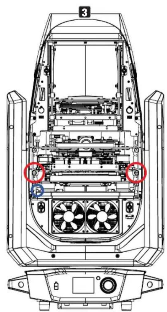
- Carefully disconnect the four-pin plug connection for the power and signal supply of the gobo module (blue marking in the illustration). Then loosen the two screws of the gobo module (centre module, see red markings in the drawing) and pull the module out of the device head.
natural_image
Technical line drawing of a vehicle's internal components, showing fan and motor assembly (no text or symbols)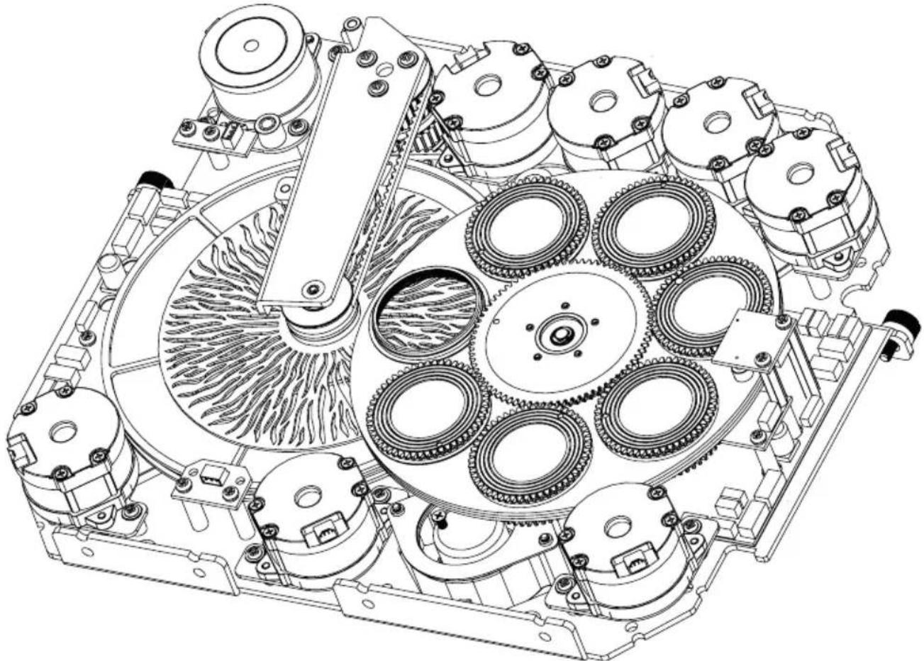
natural_image
Technical line drawing of an internal mechanical assembly with multiple gears and shafts (no text or symbols)- Place the module on a clean, level surface with the gobo wheels facing upwards. To avoid contaminating the gobos and other components, please wear clean, lint-free gloves.
- Removing the gobo holder
Removing the gobo holder in the upper gobo wheel:
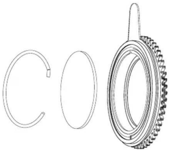
- Lift the gobo holder slightly up on the gear and then pull it out of the gobo wheel.
Removing the gobo holder in the lower gobo wheel: - Slide the swivel arm with the animation wheel to the edge of the module as far as it will go.
- Turn the two colour wheels with "OPEN" over the opening in the centre of the module.
- Turn the upper gobo wheel with "OPEN" over the opening in the centre of the module.
- Turn the lower gobo wheel until the desired gobo is positioned over the opening in the centre of the module.
- Grab onto the gobo from above and from below using one finger from each hand, press it down slightly, and then pull the gobo with the gobo holder to the side and out of the gobo wheel.
- The gobo can now be removed from the holder and replaced with another one.
natural_image
Technical line drawing of a mechanical gear assembly with three views: circular, oval, and toroidal (no text or symbols)- Then place the gobo holder back into the respective gobo wheel, ensuring that the gobo holder is correctly positioned in the corresponding recess. For rotating gobos, you can check that the gobo is positioned correctly by turning the gobo wheel. The gobo must rotate without catching.
- Re-install the module in the light head, secure it with the two previously loosened screws, and reconnect the plug for the power and signal supply to the corresponding port.
- Re-attach the cover's safety cable to the corresponding position in the device head, place the cover on the device head, and secure it with the four locks (bayonet lock, 1/4 turn to the right).
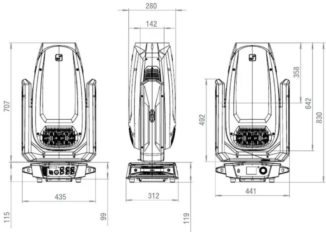
DIMENSIONS (mm)
TECHNICAL DATA
| Photometric data | |
| Illuminant type LED | |
| Light output 1400 W | |
| Lighting power 50,000 lm | |
| Light intensity – indicated value 37,000 lx | |
| Light intensity – distance 10 m | |
| Light intensity – angle 5.5° | |
| Light intensity (2) – indicated value 1,100 lx | |
| Light intensity (2) – distance 10 m | |
| Light intensity (2) – angle 48° | |
| Diameter front lens 193 mm | |
| Beam angle 5.5°–48° | |
| Field angle 6°–50° | |
| Focusing Motorised | |
| LED PWM frequency | 650 Hz; 1,530 Hz; 3,600 Hz; 12 kHz; 18.9 kHz; 25 kHz |
| Dimmer resolution | 16 bit |
| Dimmer curves | Linear; exponential; logarithmic; S-curve |
| Colours | |
| Colour mixing functions | CMY + CTO |
| LED colours White | |
| Correlated colour temperature (CCT) | 6000K |
| CTO function | Linear CTO + Fixed CTO/CTB Filter on second colour wheel |
| Min. colour rendering index (CRI) | 69 (high CRI filter: 90) |
| Colour wheels | 2 |
| Colour wheel 1 – functions | Scroll/snap |
| Colour wheel 1 – colours | Open; Deep Red; Medium Blue; Deep Green; Amber; Deep Blue |
| Colour wheel 2 – functions | Scroll/snap |
| Colour wheel 2 – colours | Open; CTO 2600K; CTO 3200K; CTB 7500K; CTB 9000K; High CRI |
| Movement | |
| Pan | 0°–270° |
| Tilt | 0°–540°/630° |
| Effects | |
| Gobo wheels | 2 |
| Gobo wheel 1 – functions | Rotatable + indexable + scroll/snap |
| Gobo wheel 1 – gobos | 6 + Open |
| Gobo wheel 2 – functions | Rotatable + indexable + scroll/snap |
| Gobo wheel 2 – gobos | 6 + Open |
Prism levels 1 plane with 2 prisms
Strobe 1–20 Hz
Iris Yes
Frost 2 × on the same level
Animation Yes
Aperture slider Yes
Rotation module +/- 60°
Control system
| Control protocols | Art-Net, CRMX, DMX512; RDM, sACN, W-DMX (transceiver) |
| Number of DMX control modes 3 | |
| Further DMX functions System settings | |
| Stand-alone operating modes | Play Scene; Play Loop; Master-Slave; Slave Grouping |
| Special features in the system settings | Mains-independent configuration of system settings possible |
| Data input connection RJ45 socket | |
| Data output connector RJ45 socket |
Mains operation
| Operating voltage 100–240 V AC 50–60 Hz | |
| Power consumption | 1670 W |
| Min. power factor Cos Phi (230 V) | 0.99 |
| Current consumption | 7.3 A |
| Mains connection TRUE1-compatible | |
| Fuse | T25AL/250 V |
| Fuse replacement | Possible from the outside without opening |
Housing
| Housing material | ABS |
| Surface coating | Powder-coated |
| Colour | Black |
Cooling
| Cooling system | Temperature-dependent fan control |
| Cooling modes | Auto, Maximum, Silent, On/Off |
Ambient conditions
| Protection class | IP20 |
| Risk group | RG2 |
| Ambient temperature | 0–40°C |
| Maximum humidity | <80%, non-condensing |
| Minimum distance to illuminated surface | 5 m |
| Minimum distance to normally flammable materials | 0.5 m |
Dimensions and weight
Width 441 mm
Height 830 mm
Depth 312 mm
Weight 44.0 kg
Additional features
Included accessories 2 × omega bracket + mains cable
MINIMUM DISTANCE TO ILLUMINATED SURFACE

This symbol with the distance stated in metres (m) indicates the minimum distance of the light fixture to the illuminated surface. The value valid for this device can be found in the technical data in this manual and is printed on the device!
MINIMUM DISTANCE TO NORMALLY FLAMMABLE MATERIALS
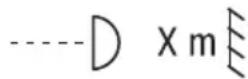
This symbol with the distance stated in metres (m) indicates the minimum distance of the device to normally flammable materials. The value valid for this device can be found in the technical data in this manual!
DISPOSAL

PACKAGING:
- Packaging can be recycled using the usual disposal methods.
- Please separate the packaging in accordance with the disposal laws and recycling regulations in your country.

DEVICE:
- This device is subject to the European Directive on Waste Electrical and Electronic Equipment, as amended. WEEE Directive Waste Electrical and Electronic Equipment. Waste equipment does not belong in household waste. Waste equipment must be disposed of via an authorised waste disposal company or a municipal waste disposal facility. Please observe the applicable regulations in your country!
- Observe all disposal laws applicable in your country.
- As a private customer, you can obtain information on environmentally friendly disposal options from the seller of the product or the appropriate regional authorities.
MANUFACTURER'S DECLARATIONS
Manufacturer's warranty and limitation of liability
Adam Hall GmbH | Adam-Hall-Str.1 | 61267 Neu-Anspach | Germany
Email: Info@adamhall.com / +49 (0)6081 / 9419-0
Our current warranty conditions and limitation of liability can be found at:
https://cdn-shop.adamhall.com/media/pdf/Manufacturers-Declarations-CAMEO_DE_EN_ES_FR.pdf
For service requests, please contact your distribution partner.
CE conformity
Adam Hall GmbH hereby confirms that this product meets the following guidelines
(where applicable):
Low-Voltage Directive (2014/35/EU)
EMC Directive (2014/30/EU)
RoHS (2011/65/EU)
RED (2014/53/EU)
EC Declaration of Conformity
Declarations of conformity for products subject to the LVD, EMC, and RoHS Directives can be requested from info@adamhall.com
Declarations of conformity for products subject to RED can be downloaded from www.adamhall.com/compliance/
Subject to misprints and errors, as well as technical or other modifications!
DEUTSCH

HINWEISE FÜR ORTSVERÄNDERLICHE INDOOR-GERÄTE
flowchart
graph LR
    A["Master Unit\nMaster Delay 0.5s"] --> B["Slave Group\n00"]
    B --> C["Slave Group\n01"]
    C --> D["Slave Group\n02"]
    D --> E["Slave Group\n03"]
    E --> F["Slave Group\n04"]
    F --> G["Slave Group\n05"]
    B --> H["No Delay"]
    C --> I["0.5s Delay"]
    D --> J["1s Delay"]
    E --> K["1.5s Delay"]
    F --> L["2s Delay"]
    G --> M["2.5s Delay"]
    E --> N["Slave Group\n03"]
    F --> O["Slave Group\n03"]
| ----Menu---- | |
| Control | |
| Settings | |
| Info | |
| Service | |
| Quicklight | |
| ▶ Help | |
| --------Help-------- |
| Shortcuts |
| Turn encoder in the home screen to change the DMR address |
| Push & turn-right to jump to the latest selected menu point |
| Push BACK for 3 seconds to jump to the home screen without saving |
| Back | Other |
| Cameo |
| Opus X4 |
| Cameo* Is a brand of the Adam Hall Groupwww.adamhall.com |
Abbildung 1
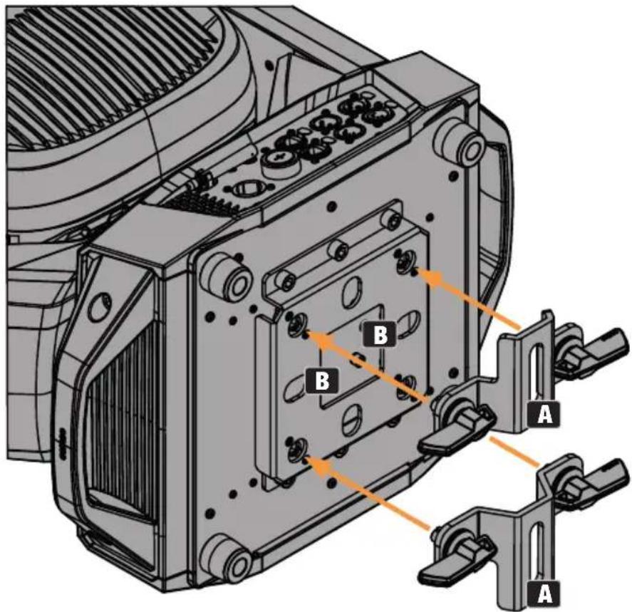
Abbildung 2

GEBRAUCHSLAGE
natural_image
Technical line drawing of a vehicle's internal components, showing fan and motor assembly (no text or symbols)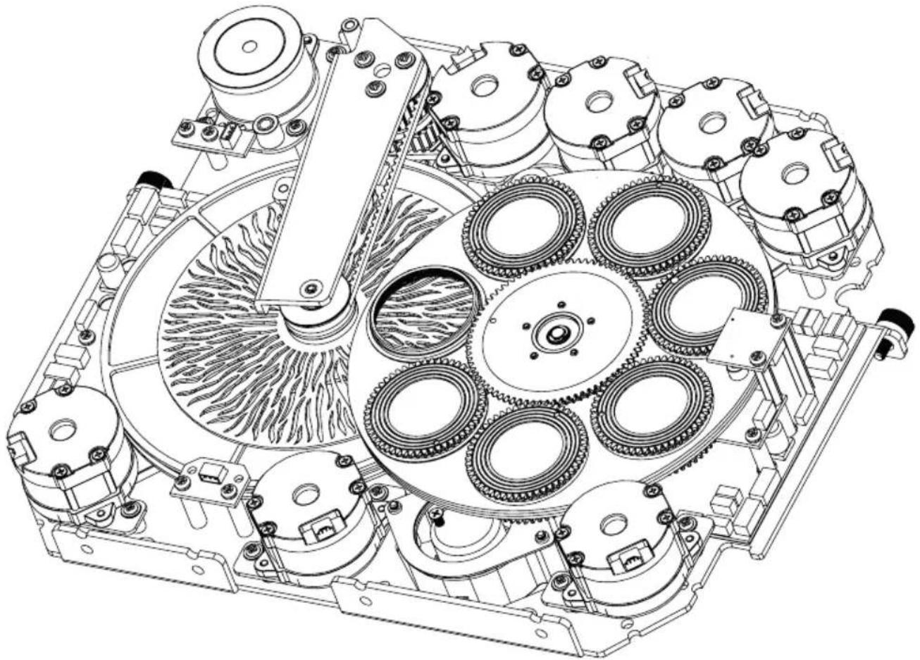
natural_image
Technical line drawing of an internal mechanical assembly with multiple gears and shafts (no text or labels)natural_image
Technical line drawing of mechanical components including a coiled spring and a meshed gear (no text or symbols)https://cdn-shop.adamhall.com/media/pdf/Manufacturers-Declarations-CAMEO_DE_EN_ES_FR.pdf
▶ 1 Lyre asservie OPUS X4 Profile
INTRODUCTION
| Network | |
| Protocol | |
| Universe | |
| IP Address | |
| Subnet Mask | |
| Signal Routing |
flowchart
graph LR
    A["Master Unit\nMaster Delay 0.5s"] --> B["Slave Group\n00"]
    B --> C["Slave Group\n01"]
    C --> D["Slave Group\n02"]
    D --> E["Slave Group\n03"]
    E --> F["Slave Group\n03"]
    E --> G["Slave Group\n03"]
    F --> H["Slave Group\n04"]
    G --> I["Slave Group\n05"]
PARAMÈTRES SYSTÈME (Settings)
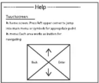

Illustration 1
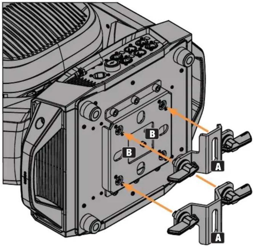
Illustration 2

ENTRETIEN, MAINTENANCE ET RÉPARATION
REPLACEMENT DES GOBOS

ATTENTION :
natural_image
Technical line drawing of a mechanical device interior with labeled components (no text or symbols present)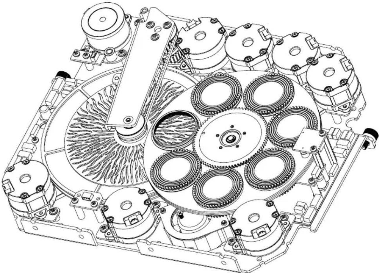
natural_image
Technical line drawing of an internal mechanical assembly with multiple gears and shafts (no text or symbols)natural_image
Technical line drawing of a mechanical gear assembly with two circular components and a meshed ring (no text or symbols)https://cdn-shop.adamhall.com/media/pdf/Manufacturers-Declarations-CAMEO_DE_EN_ES_FR.pdf
Directive CEM (2014/30/UE)
RoHS (2011/65/EU)
RED (2014/53/EU)

NOTAS PARA EQUIPOS PORTÁTILES QUE SE INSTALAN EN INTERIORES
| Network | |
| Protocol | |
| Universe | |
| IP Address | |
| Subnet Mask | |
| Signal Routing |
flowchart
graph LR
    A["Master Unit\nMaster Delay 0.5s"] --> B["Slave Group\n00"]
    B --> C["Slave Group\n01"]
    C --> D["Slave Group\n02"]
    D --> E["Slave Group\n03"]
    E --> F["Slave Group\n03"]
    E --> G["Slave Group\n03"]
    F --> H["Slave Group\n04"]
    H --> I["Slave Group\n05"]
    style A fill:#f9f,stroke:#333
    style I fill:#f9f,stroke:#333
AJUSTES DEL SISTEMA (Settings)

Atajos
Figura 1
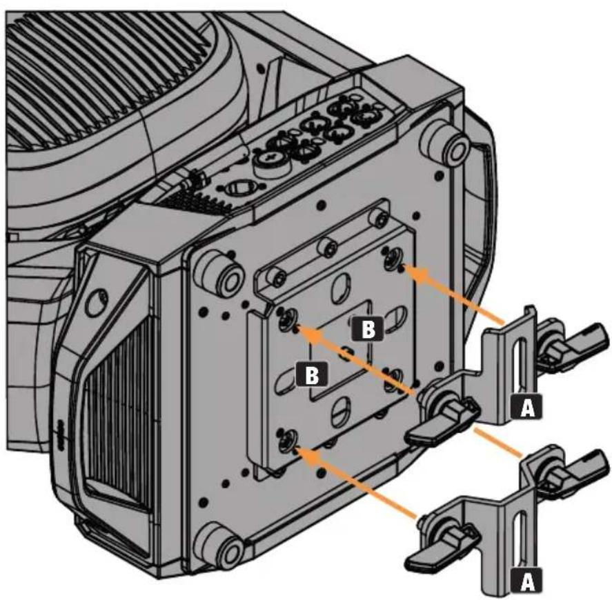
Figura 2

POSICIÓN DE USO
natural_image
Technical line drawing of a mechanical gear assembly with two views: one showing a loop and the other showing a meshed gear (no text or symbols)| Horizontal 0°-270° |
| Vertical 0°-540°/630° |
Efectos

| ----Menu---- | |
| ▶ Control | |
| Settings | |
| Info | |
| Service | |
| Quicklight | |
| Help |
| Control | |
| DMX Address | |
| DMX Mode | |
| Network | |
| Stand Alone | |
| Slave | Group 00 |
| Network | |
| Protocol | |
| Universe | |
| IP Address | |
| Subnet Mask | |
| Signal Routing |
flowchart
graph LR
    A["Master Unit\nMaster Delay 0.5s"] --> B["Slave Group\n00"]
    B --> C["Slave Group\n01"]
    C --> D["Slave Group\n02"]
    D --> E["Slave Group\n03"]
    E --> F["Slave Group\n03"]
    F --> G["Slave Group\n03"]
    G --> H["Slave Group\n04"]
    H --> I["Slave Group\n05"]
    style A fill:#f9f,stroke:#333
    style I fill:#f9f,stroke:#333
| ----Menu---- | |
| Control | |
| ▶ Settings | |
| Info | |
| Service | |
| Quicklight | |
| Help |
| Settings | |
| Wireless | |
| Display | |
| Dimmer | |
| Movement | |
| Wheels | |
| Fan | |
| Signal Fail | |
| Store |
KONFIGURACJA I INSTALACJA

llustracja 1
llustracja 2

PIELEGNACJA, KONSERWACJA I NAPRAWA
natural_image
Technical line drawing of a vehicle's internal components, showing fan and motor assembly (no text or labels)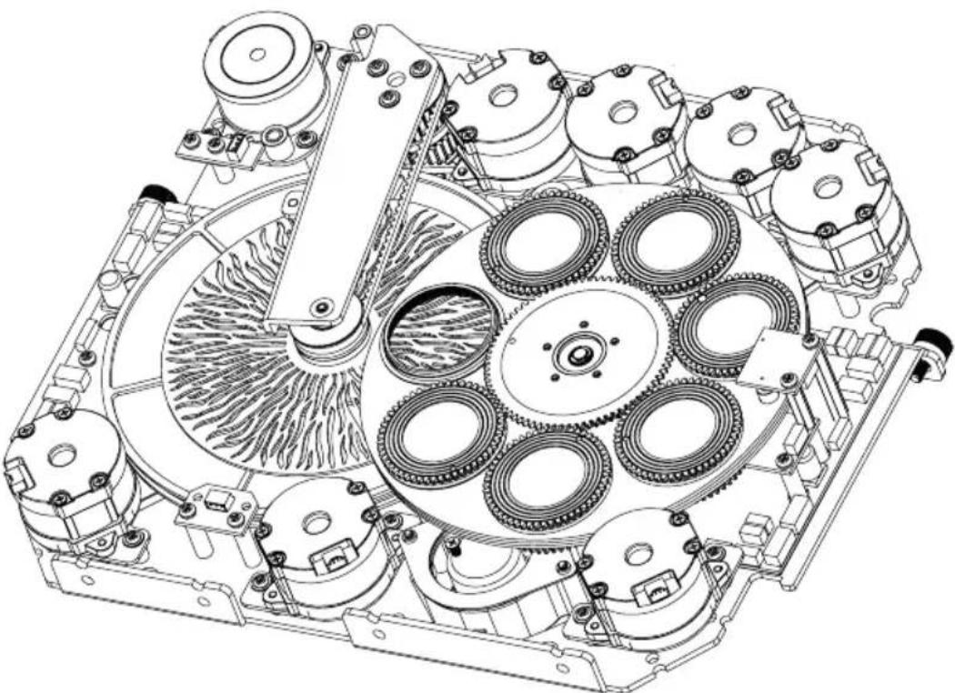
natural_image
Technical line drawing of a mechanical assembly with multiple gears and housing (no text or symbols)natural_image
Technical line drawing of a mechanical gear assembly with three views: circular, oval, and toroidal (no text or symbols)Obrót 0°–270° Tilt 0°–540°/630°
Efekty
https://cdn-shop.adamhall.com/media/pdf/Manufacturers-Declarations-CAMEO_DE_EN_ES_FR.pdf

NOTE PER I DISPOSITIVI MOBILI PER INTERNI
13 IMPUGNATURE A INCASSO
| Network | |
| Protocol | |
| Universe | |
| IP Address | |
| Subnet Mask | |
| Signal Routing |
flowchart
graph LR
    A["Master Unit\nMaster Delay 0.5s"] --> B["Slave Group\n00"]
    B --> C["Slave Group\n01"]
    C --> D["Slave Group\n02"]
    D --> E["Slave Group\n03"]
    E --> F["Slave Group\n03"]
    F --> G["Slave Group\n03"]
    G --> H["Slave Group\n04"]
    H --> I["Slave Group\n05"]
    style B stroke:#000,stroke-width:2px
    style C stroke:#000,stroke-width:2px
    style D stroke:#000,stroke-width:2px
    style E stroke:#000,stroke-width:2px
    style F stroke:#000,stroke-width:2px
    style G stroke:#000,stroke-width:2px
    style H stroke:#000,stroke-width:2px
    style I stroke:#000,stroke-width:2px
IMPOSTAZIONI DI SISTEMA (Settings)

Scorciatoie
Figura 1
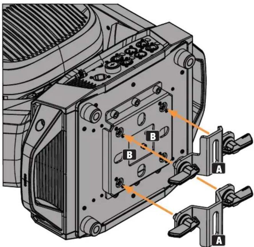
Figura 2

natural_image
Technical line drawing of a mechanical gear assembly with two circular components and a meshed shaft (no text or symbols)| Pan 0°–270° |
| Tilt 0°-540°/630° |
Effetti
https://cdn-shop.adamhall.com/media/pdf/Manufacturers-Declarations-CAMEO DE EN ES FR.pdf
| 34CHBasic | 41CHStandard | 56CHExtended | |||||||
| Channel | Channel | Channel | Function | Values | Subgroup | Group | |||
| 1 1 1 | Pan 000 | -255 0% to 100% | Pan | Move- | ment | ||||
| 2 2 2 | Pan fine | 000 - 255 | |||||||
| 3 3 3 | Tilt 000 | -255 0% to 100% | Tilt | ||||||
| 4 4 4 | Tilt fine | 000 - 255 | |||||||
| 5 5 5 | Dimmer | 000 - 255 0% to 100% | 000 | Dimmer Intensity | |||||
| 6 6 Dimmer | fine | 000 | 255 | ||||||
| 6 7 7 | Strobe | Functions | 000 | 005 Open Multi- | functional Strobe | Strobe | |||
| 006 | 010 Closed | ||||||||
| 011 | 022 Ramp up/down slow to fast | ||||||||
| 023 | 033 Ramp up/down random slow to fast | ||||||||
| 034 | 045 Ramp up slow to fast | ||||||||
| 046 | 056 Ramp up random slow to fast | ||||||||
| 057 | 068 Ramp down slow to fast | ||||||||
| 069 | 079 Ramp down random slow to fast | ||||||||
| 080 | 102 Random Strobe effect slow to fast | ||||||||
| 103 | 127 Strobe Break effect 5s to 1s (short burst with break) | ||||||||
| 128 | 250 Strobe slow to fast (<1Hz to 20Hz) | ||||||||
| 251 | 255 Open | ||||||||
| 8 LED | Segment Dim | 000 | 005 All segments on LED | Segment Control | LED Segments | ||||
| 8 LED | Segment Dim | 006 - | 17 | 7 Fade | Sparkle FX in 0 - 100% | LED Segment Control | LED Segments | ||
| 178 - | 18 | 0 Only | LED segment 1 on | ||||||
| 181 - | 18 | 3 Only | LED segment 2 on | ||||||
| 184 - | 18 | 6 Only | LED segment 3 on | ||||||
| 187 - | 18 | 9 Only | LED segment 4 on | ||||||
| 190 - | 19 | 2 Only | LED segment 5 on | ||||||
| 193 - | 19 | 5 Only | LED segment 6 on | ||||||
| 196 - | 19 | 8 Only | LED segment 7 on | ||||||
| 199 - | 20 | 1 Only | LED segment 8 on | ||||||
| 202 - | 20 | 4 Only | LED segment 9 on | ||||||
| 205 - | 20 | 7 Only | LED segment 1 & 2 & 3 on | ||||||
| 208 - | 21 | 0 Only | LED segment 4 & 5 & 6 on | ||||||
| 211 - | 21 | 3 Only | LED segment 7 & 8 & 9 on | ||||||
| 214 - | 21 | 6 Only | LED segment 1 & 3 & 5 & 7 & 9 on | ||||||
| 217 - | 21 | 9 Only | LED segment 2 & 4 & 6 & 8 on | ||||||
| 220 - | 22 | 2 Only | LED segment 1 & 9 on | ||||||
| 223 - | 22 | 5 Only | LED segment 2 & 8 on | ||||||
| 226 - | 22 | 8 Only | LED segment 3 & 7 on | ||||||
| 229 - | 23 | 1 Only | LED segment 4 & 5 on | ||||||
| 232 - | 23 | 4 Only | LED segment 1 & 2 on | ||||||
| 235 - | 23 | 7 Only | LED segment 2 & 3 on | ||||||
| 238 - | 24 | 0 Only | LED segment 3 & 4 on | ||||||
| 241 - | 24 | 3 Only | LED segment 4 & 5 on | ||||||
| 244 - | 24 | 6 Only | LED segment 5 & 6 on | ||||||
| 247 - | 24 | 9 Only | LED segment 6 & 7 on | ||||||
| 8 LED | Segment Dim | 250 - | 25 | 2 Only | LED segment 7 & 8 on | LED Segment Control | LED Segments | ||
| 253 - | 25 | 5 Only | LED segment 8 & 9 on | ||||||
| 9 Sparkle FX | 000 - | 00 | 5 No function LED | Segment Chaser | |||||
| 006 - | 02 | 0 Chaser 1 jump (slow to fast) | |||||||
| 021 - | 03 | 5 Chaser 2 jump (slow to fast) | |||||||
| 036 - | 05 | 0 Chaser 3 jump (slow to fast) | |||||||
| 051 - | 06 | 5 Chaser 4 jump (slow to fast) | |||||||
| 066 - | 08 | 0 Chaser 5 jump (slow to fast) | |||||||
| 081 - | 09 | 5 Chaser 6 jump (slow to fast) | |||||||
| 096 - | 11 | 0 Chaser 7 jump (slow to fast) | |||||||
| 111 - | 12 | 5 Chaser 8 jump (slow to fast) | |||||||
| 126 - | 14 | 0 Chaser 1 fade (slow to fast) | |||||||
| 141 - | 15 | 5 Chaser 2 fade (slow to fast) | |||||||
| 156 - | 17 | 0 Chaser 3 fade (slow to fast) | |||||||
| 171 - | 18 | 5 Chaser 4 fade (slow to fast) | |||||||
| 186 - | 20 | 0 Chaser 5 fade (slow to fast) | |||||||
| 201 - | 21 | 5 Chaser 6 fade (slow to fast) | |||||||
| 216 - | 23 | 0 Chaser 7 fade (slow to fast) | |||||||
| 231 - | 24 | 5 Chaser 8 fade (slow to fast) | |||||||
| 246 - | 25 | 5 No function | |||||||
| 7 8 10 | Cyan 000 - 255 0% to 100 % Sub- | tractiveColourMixing | Colour | ||||
| 11 Cyan fine 000 - 255 | |||||||
| 8 9 12 | Magenta 000 - 255 0% to 100% | ||||||
| 13 Magentafine | 000 - 255 | ||||||
| 9 10 14 | Yellow 000 - 255 0% to 100% | ||||||
| 15 Yellowfine | 000 - 255 | ||||||
| 10 11 | 16 CTO 000 - 255 0% to 100% | ||||||
| 17 CTO fine 000 - 255 | |||||||
| 11 12 | 18 Colour | Wheel 1 | 000 - 000 Open Colour | Wheel 1 | |||
| 001 - 031 Open -> Deep Red | |||||||
| 032 - 032 Deep Red | |||||||
| 033 - 063 Deep Red -> MediumBlue | |||||||
| 064 - 064 Medium Blue | |||||||
| 065 - 095 Medium Blue -> DeepGreen | |||||||
| 096 - 096 Deep Green | |||||||
| 097 - 127 Deep Green -> Amber | |||||||
| 128 - 128 Amber | |||||||
| 129 - 159 Amber -> Deep Blue | |||||||
| 160 - 160 Deep Blue | |||||||
| 161 - 191 Deep Blue -> Open | |||||||
| 192 - 192 Open | |||||||
| 193 - 223 Colour Wheel Rotationfast to slow | |||||||
| 224 - 224 Colour Wheel Rotationstop | |||||||
| 225 - 255 Colour Wheel Rotationslow to fast (back-wards) | |||||||
| 12 13 | 19 Colour | Wheel 2 | 000 - 000 Open Colour | Wheel 2 | |||
| 001 - 031 Open -> CTO 2600K | |||||||
| 032 - 032 CTO 2600K | |||||||
| 033 - 063 CTO 2600K -> CTO3200K | |||||||
| 064 - 064 CTO 3200K | |||||||
| 065 - 095 CTO 3200K -> CTB7500K | |||||||
| 096 - 096 CTB 7500K | |||||||
| 097 - 127 CTB 7500K -> CTB9000K | |||||||
| 12 13 | 19 Colour | Wheel 2 | 128 - 128 CTB 9000K Colour | Wheel 2 | Colour | |||
| 129 - 159 CTB 9000K -> High CRI | ||||||||
| 160 - 160 High CRI | ||||||||
| 161 - 191 High CRI -> Open | ||||||||
| 192 - 192 Open | ||||||||
| 193 - 223 Colour Wheel Rotation fast to slow | ||||||||
| 224 - 224 Colour Wheel Rotation stop | ||||||||
| 225 - 255 Colour Wheel Rotation slow to fast (back- wards) | ||||||||
| 13 14 | 20 Gobo | Wheel 1 | 000 - 005 Open Gobo | Wheel 1 (rotating Gobos) | Gobo | |||
| 006 - 023 Open -> Gobo1 | ||||||||
| 024 - 024 Gobo 1 | ||||||||
| 025 - 042 Gobo 1 -> Gobo 2 | ||||||||
| 043 - 043 Gobo 2 | ||||||||
| 044 - 061 Gobo 2 -> Gobo 3 | ||||||||
| 062 - 062 Gobo 3 | ||||||||
| 063 - 080 Gobo 3 -> Gobo 4 | ||||||||
| 081 - 081 Gobo 4 | ||||||||
| 082 - 099 Gobo 4 -> Gobo 5 | ||||||||
| 100 - 100 Gobo 5 | ||||||||
| 101 - 118 Gobo 5 -> Gobo 6 | ||||||||
| 119 - 119 Gobo 6 | ||||||||
| 120 - 137 Gobo 6 -> Open | ||||||||
| 138 - 142 Open | ||||||||
| 143 - 149 Gobo 1 Shake (slow -> fast) | ||||||||
| 150 - 156 Gobo 2 Shake (slow -> fast) | ||||||||
| 157 - 163 Gobo 3 Shake (slow -> fast) | ||||||||
| 164 - 170 Gobo 4 Shake (slow -> fast) | ||||||||
| 171 - 177 Gobo 5 Shake (slow -> fast) | ||||||||
| 178 - 184 Gobo 6 Shake (slow -> fast) | ||||||||
| 185 - 192 Open | ||||||||
| 193 - 223 Gobo Wheel rotation fast to slow | ||||||||
| 13 14 | 20 Gobo | Wheel 1 | 224 - | 224 Gobo | Wheel rotation Stop | Gobo Wheel 1 (rotating Gobos) | Gobo | |
| 225 - | 255 Gobo | Wheel rotation slow to fast (backwards) | ||||||
| 14 15 | 21 Gobo | Wheel 1 Gobo Position | 000 - | 128 Gobo | Position 0^ ... 540^ | |||
| 129 - | 191 Gobo | Rotation fast to slow | ||||||
| 192 - | 192 Gobo | Rotation Stop | ||||||
| 193 - | 255 Gobo | Rotation slow to fast (backwards) | ||||||
| 16 22 | Gobo | Wheel 1 Gobo Position fine | 000 - | 255 Gobo | Position fine | |||
| 15 17 | 23 Gobo | Wheel 2 | 000 - | 005 Open | Gobo | Wheel 2 (rotating Gobos) | ||
| 006 - | 023 Open -> Gobo1 | |||||||
| 024 - | 024 Gobo 1 | |||||||
| 025 - | 042 Gobo 1 -> Gobo 2 | |||||||
| 043 - | 043 Gobo 2 | |||||||
| 044 - | 061 Gobo 2 -> Gobo 3 | |||||||
| 062 - | 062 Gobo 3 | |||||||
| 063 - | 080 Gobo 3 -> Gobo 4 | |||||||
| 081 - | 081 Gobo 4 | |||||||
| 082 - | 099 Gobo 4 -> Gobo 5 | |||||||
| 100 - | 100 Gobo 5 | |||||||
| 101 - | 118 Gobo 5 -> Gobo 6 | |||||||
| 119 - | 119 Gobo 6 | |||||||
| 120 - | 137 Gobo 6 -> Open | |||||||
| 138 - | 142 Open | |||||||
| 143 - | 149 Gobo 1 Shake (slow -> fast) | |||||||
| 150 - | 156 Gobo 2 Shake (slow -> fast) | |||||||
| 157 - | 163 Gobo 3 Shake (slow -> fast) | |||||||
| 164 - | 170 Gobo 4 Shake (slow -> fast) | |||||||
| 171 - | 177 Gobo 5 Shake (slow -> fast) | |||||||
| 15 17 | 23 Gobo | Wheel 2 | 178 | 184 | Gobo 6 Shake (slow -> fast) | Gobo Wheel 2 (rotating Gobos) | Gobo | |
| 185 | 192 | Open | ||||||
| 193 | 223 | Gobo Wheel rotation fast to slow | ||||||
| 224 | 224 | Gobo Wheel rotation Stop | ||||||
| 225 | 255 | Gobo Wheel rotation slow to fast (back- wards) | ||||||
| 16 18 | 24 Gobo | Wheel 2 Gobo Position | 000 | 128 | Gobo Position 0^ ·s 540^ | |||
| 129 | 191 | Gobo Rotation fast to slow | ||||||
| 192 | 192 | Gobo Rotation Stop | ||||||
| 193 | 255 | Gobo Rotation slow to fast (backwards) | ||||||
| 19 25 | Gobo | Wheel 2 Gobo Position fine | 000 | 255 | Gobo Position fine | |||
| 17 20 | 26 Zoom | 000 - | 255 Narrow to Wide Zoom Beam | |||||
| 27 Zoom fine 000 | - 255 | |||||||
| 18 21 | 28 Focus | 000 - | 255 0% to 100% Focus | |||||
| 22 29 | Focus fine | 000 - 255 | ||||||
| 23 30 | Auto | Focus | 000 - 005 No function | |||||
| 006 - 036 3m | ||||||||
| 037 - 067 5m | ||||||||
| 068 - 098 10m | ||||||||
| 099 - 129 15m | ||||||||
| 130 - 160 20m | ||||||||
| 161 - 191 30m | ||||||||
| 192 - 222 50m | ||||||||
| 223 - 255 100m | ||||||||
| 24 31 | Auto | Focus Adjust | 000 - 255 Auto Focus Adjustment | |||||
| 19 25 | 32 Iris | 000 - 191 Open to Close | Close Iris | |||||
| 192 - 200 Pulse slow to fast (with Dim) | ||||||||
| 19 25 | 32 Iris 201 - 209 | Pulse slow | to fast | (without Dim) | Iris Beam | ||
| 210 | 21 | 8 Pulse Random slow to fast (without Dim) | |||||
| 219 | 22 | 7 Ramp up slow to fast (with Dim) | |||||
| 228 | 23 | 6 Ramp up slow to fast (without Dim) | |||||
| 237 | 24 | 5 Ramp down slow to fast (with Dim) | |||||
| 246 | 25 | 5 Ramp down slow to fast (without Dim) | |||||
| 20 26 | 33 Prism | Selection | 000 | 005 No Prism Prism | |||
| 006 | 130 Prism 1 (5-face circular) | ||||||
| 131 | 255 Prism 2 (8-face circular) | ||||||
| 21 27 | 34 Prism | Rotation | 000 | 128 Prism Position 0^ to 540^ | |||
| 129 | 191 Prism Rotation fast to slow | ||||||
| 192 | 192 Prism Rotation Stop | ||||||
| 193 | 255 Prism Rotation slow to fast (backwards) | ||||||
| 22 28 | 35 Frost | 000 - 000 No Frost | Frost | ||||
| 001 | 128 0% to 100% Light Frost | ||||||
| 129 | 129 No Frost | ||||||
| 130 | 255 0% to 100% Medium Frost | ||||||
| 23 29 | 36 Animation | Wheel | 000 | 255 Animation Wheel In 0 - 100% | Animation Wheel | ||
| 24 30 | 37 Animation | Wheel Rotation | 000 | 128 Animation Wheel Posi- tion 0^ to 540^ | |||
| 129 | 191 Animation Wheel Rota- tion fast to slow | ||||||
| 192 | 192 Animation Wheel Rota- tion Stop | ||||||
| 193 | 255 Animation Wheel Rotation slow to fast (backwards) |
| 25 31 | 38 Blade | 1A 000 | - 255 0% | - 100% | Framing | Blades | Framing | |
| 39 Blade | 1A fine | 000 - | 255 | |||||
| 26 32 | 40 Blade | 1B 000 | - 255 0% | - 100% | ||||
| 41 Blade | 1B fine | 000 - | 255 | |||||
| 27 33 | 42 Blade | 2A 000 | - 255 0% | - 100% | ||||
| 43 Blade | 2A fine | 000 - | 255 | |||||
| 28 34 | 44 Blade | 2B 000 | - 255 0% | - 100% | ||||
| 45 Blade | 2B fine | 000 - | 255 | |||||
| 29 35 | 46 Blade | 3A 000 | - 255 0% | - 100% | ||||
| 47 Blade | 3A fine | 000 - | 255 | |||||
| 30 36 | 48 Blade | 3B 000 | - 255 0% | - 100% | ||||
| 49 Blade | 3B fine | 000 - | 255 | |||||
| 31 37 | 50 Blade | 4A 000 | - 255 0% | - 100% | ||||
| 51 Blade | 4A fine | 000 - | 255 | |||||
| 32 38 | 52 Blade | 4B 000 | - 255 0% | - 100% | ||||
| 53 Blade | 4B fine | 000 - | 255 | |||||
| 33 39 | 54 Shape | Rotation | 000 - | 255 0% | - 100% Rotation | |||
| 40 55 | Shape | Rotation fine | 000 - | 255 | ||||
| 34 41 56 | ||||
| Device Settings(all settings executed are after holding value for 3 seconds) (please read remark 1*) | ||||
| 000 - 005 No function Control | Blackout | |||
| 006 - 007 Blackout while P/Tmoving On | ||||
| 008 - 009 Blackout while P/Tmoving Off | ||||
| 010 - 011 Blackout while Wheelsmoving On | ||||
| 012 - 013 Blackout while Wheelsmoving Off | ||||
| 014 - 017 No function | ||||
| 018 - 019 Sleep Mode On Energy | Saving | |||
| 020 - 021 Sleep Mode Off/WakeUp | ||||
| 022 - 024 No function | ||||
| 025 - 025 Record Scene 1 User | Colours | |||
| 026 - 026 Record Scene 2 | ||||
| 027 - 027 Record Scene 3 | ||||
| 028 - 028 Record Scene 4 | ||||
| 029 - 029 Record Scene 5 | ||||
| 030 - 030 Record Scene 6 | ||||
| 031 - 031 Record Scene 7 | ||||
| 032 - 032 Record Scene 8 | Colours | |||
| 033 - 041 No function | ||||
| 042 - 043 Invert Pan On Move- | ment | |||
| 044 - 045 Invert Pan Off | ||||
| 046 - 047 Invert Tilt On | ||||
| 048 - 049 Invert Tilt Off | ||||
| 050 - 051 Pan Angle 540° | ||||
| 052 - 053 Pan Angle 630° | ||||
| 054 - 073 No Function | ||||
| 074 - 075 Dimmer Response LED Dimming | ||||
| 076 - 077 Dimmer Response Halogen | ||||
| 078 - 093 No function | ||||
| 094 - 095 Silent movement On Noise | Functions | |||
| 096 - 097 Silent movement Off | ||||
| 098 - 099 Fan Auto | ||||
| 100 - 101 Fan Off | ||||
| 102 - 103 Fan Constant Low | ||||
| 104 - 105 Fan Constant Medium | ||||
| 106 - 107 Fan Constant High | ||||
| 108 - 119 No function | ||||
| 34 41 56 | Device Settings(all settings executed are after holding value for 3 seconds) (please read remark 1*) | 120 - 121 PWM 1 (650 Hz) PWM Fre- | quency | Control | ||
| 122 - 123 PWM 2 (1530 Hz) | ||||||
| 124 - 125 PWM 3 (3600 Hz) | ||||||
| 126 - 127 PWM 4 (12000 Hz) | ||||||
| 128 - 129 PWM 5 (18900 Hz) | ||||||
| 130 - 131 PWM 6 (25000 Hz) | ||||||
| 132 - 139 No function | ||||||
| 140 - 141 Display Always On Display | ||||||
| 142 - 143 Display Off after 20s | Functions | |||||
| 144 - 147 No function | ||||||
| 148 - 149 Colour Wheel Snap Wheel | ||||||
| 150 - 151 Colour Wheel Scroll | Move-ment | |||||
| 152 - 153 Gobo Wheel Snap | ||||||
| 154 - 155 Gobo Wheel Scroll | GoboColourCorrec-tion | |||||
| 156 - 157 Gobo Colour CorrectionOn | ||||||
| 158 - 159 Gobo Colour CorrectionOff | ||||||
| 160 - 161 No Function Reserved | ||||||
| 162 - 163 No Function | ||||||
| 164 - 165 Dimmer Curve Linear Dimmer166 - 167 Dimmer Curve Expo- nential | Curve | |||||
| 168 - 169 Dimmer Curve Loga- rithmic | ||||||
| 170 - 171 Dimmer Curve S-Curve | ||||||
| 172 - 209 No function | ||||||
| 210 - 211 Colour Wheel Shortest Way | WheelPosition-ing | |||||
| 212 - 213 Colour Wheel Clockwise | ||||||
| 214 - 215 Gobo Wheel Shortest Way | FramingControl | |||||
| 216 - 217 Gobo Wheel Clockwise tion & Angle | ||||||
| 222 - 223 Reset Pan / Tilt Reset | ||||||
| 224 - 233 No function | ||||||
| 234 - 235 Reset Head | ||||||
| 236 - 237 Reset All | ||||||
| 238 - 239 No function |
| 34 41 | 56 | Device Settings(all settings executed are after holding value for 3 seconds) (please read remark 1*) | 240 - | 24 | 1 Load | Factory Defaults Load | Default | Control | |
| 242 - | 24 | 3 No Function | |||||||
| 244 - | 24 | 5 Load | User Default A | ||||||
| 246 - | 24 | 7 Load | User Default B | ||||||
| 248 - | 24 | 9 Load | User Default C | ||||||
| 250 - | 25 | 5 No function | |||||||
EN: (1*) After the adjustments have been made, set the value to 000 to avoid disturbance by endless function call.

- OPUS X4 PROFILE
- CONTENTS / INHALTSVERZEICHNIS / CONTENU /
- CONTENIDO / TREŚĆ / CONTENUTO
- ENGLISH
- DEUTSCH
- ESPAÑOL
- INFORMATION ON THIS USER MANUAL
- INTENDED USE
- EXPLANATIONS OF TERMS AND SYMBOLS
- SAFETY INSTRUCTIONS
- DANGER:
- WARNING:
- ATTENTION:
- CAUTION:
- CAUTION! IMPORTANT INFORMATION ON LIGHTING PRODUCTS!
- TRANSMISSION VIA W-DMX
- ATTENTION! POTENTIAL DAMAGE FROM EXTERNAL LIGHT SOURCES!
- NOTES FOR PORTABLE INDOOR DEVICES
- PACKAGING CONTENT
- INTRODUCTION
- CONTROL FUNCTIONS:
- FEATURES:
- CONNECTIONS AND OPERATING/DISPLAY ELEMENTS
- POWER IN
- FUSE
- DMX IN
- DMX OUT
- NET IN / OUT
- W-DMX™ ANTENNA
- PRESSURE-SENSITIVE LC DISPLAY WITH ILLUMINATION
- ROTARY-PUSH ENCODER
- BACK
- USB INTERFACE
- BATTERY-POWERED DISPLAY
- PAN LOCK
- TILT LOCK
- RECESSED GRIPS
- OPERATION
- PLEASE NOTE
- MAIN DISPLAY MAIN MENU AND SUB-MENUS
- W-DMX™
- W-DMX™ STATUS
- CONTROL MENU (Control)
- SETTING THE DMX START ADDRESS (DMX Address)
- SETTING THE DMX OPERATING MODE (DMX Mode)
- NETWORK SETTINGS (Network)
- STAND-ALONE MENU (Stand Alone)
- SLAVE MODE
- SYSTEM SETTINGS (Settings)
- SYSTEM INFORMATION (Info)
- SERVICE MENU (Service)
- QUICKLIGHT
- HELP (Help menu)
- SET-UP AND INSTALLATION
- CARE, MAINTENANCE, AND REPAIR
- MAINTENANCE AND REPAIR (by qualified personnel only)
- REPLACING GOBOS
- Dimensions and weight
- Additional features
- MINIMUM DISTANCE TO ILLUMINATED SURFACE
- MINIMUM DISTANCE TO NORMALLY FLAMMABLE MATERIALS
- DISPOSAL
- PACKAGING:
- DEVICE:
- MANUFACTURER'S DECLARATIONS
- Manufacturer's warranty and limitation of liability
- CE conformity
- EC Declaration of Conformity
- HINWEISE FÜR ORTSVERÄNDERLICHE INDOOR-GERÄTE
- PARAMÈTRES SYSTÈME (Settings)
- ENTRETIEN, MAINTENANCE ET RÉPARATION
- REPLACEMENT DES GOBOS
- ATTENTION :
- NOTAS PARA EQUIPOS PORTÁTILES QUE SE INSTALAN EN INTERIORES
- AJUSTES DEL SISTEMA (Settings)
- Atajos
- KONFIGURACJA I INSTALACJA
- PIELEGNACJA, KONSERWACJA I NAPRAWA
- NOTE PER I DISPOSITIVI MOBILI PER INTERNI
- IMPUGNATURE A INCASSO
- IMPOSTAZIONI DI SISTEMA (Settings)
- Scorciatoie
Brand : Cameo
Model : OPUS X4 PROFILE
Category : Lamp