IOC 100K-2LM - Camera Kern - Free user manual and instructions
Find the device manual for free IOC 100K-2LM Kern in PDF.

User questions about IOC 100K-2LM Kern
0 question about this device. Answer the ones you know or ask your own.
Ask a new question about this device
Download the instructions for your Camera in PDF format for free! Find your manual IOC 100K-2LM - Kern and take your electronic device back in hand. On this page are published all the documents necessary for the use of your device. IOC 100K-2LM by Kern.
USER MANUAL IOC 100K-2LM Kern
Further language versions you will find online under www.kern-sohn.com/manuals

natural_image
White plastic electrical enclosure with mounting holes and a central panel, no visible text or symbolsnatural_image
Exterior view of a medical imaging scale with a vertical column and base (no text or symbols visible)natural_image
Diagram of a robotic device with three labeled parts (1, 2, 3) and a connecting rod, showing no text or symbols beyond labels.natural_image
Close-up of a switch labeled 'ADJ LOCK' with wiring and connectors (no readable text beyond label)| A | B | b | C | D | E | F | G | H | h | I | J | K | L |
| I | M | N | O | P | Q | R | S | U | V | W | X | Y | Z |
8 Menü
HEADER2: NT=NET, GS=GROSS

- Menüeinstellung P2 Com → PTYPE → tPUP oder LP50
10.4 KERN Communications Protocol (KERN Schnittstellenprotokoll)
| @ Cancel | |
| I0 | List all implemented KCP commands |
| I1 | Query KCP level and KCP versions |
| I2 | Query device information (type, capacity) |
| I3 | Query device software version |
| I4 | Query serial number |
| I4_A_"xxxxxxxxx" | Set serial number (default value is K123456) |
| I5 | Query SW-Identification number |
| S | Send stable weight value |
| SI | Send weight value immediately |
| SIR | Send weight value immediately and repeat |
| Z | Zero |
| ZI | Zero immediately |
| D | Display: Write text to display |
| D_“_” | Clear Display (after D-Command) |
| DW | Display: Show weight |
| K | Keys: Set configuration |
| SR | Send weight value on weight change (send and repeat) |
| T | Tare |
| TA | Query/preset tare weight value |
| TAC | Clear tare value |
| TI | Tare immediately |

Polling-Intervall
natural_image
Close-up of a green electronic circuit board with terminal connectors and pin labels (no readable text or symbols beyond component markings)
3.4 Monitoring of Test Resources 10
4 Basic Safety Precautions.... 10
4.1 Pay attention to the instructions in the Operation Manual.... 10
4.2 Personnel training....10
5 Transport and storage.... 10
5.1 Testing upon acceptance 10
5.2 Packaging / return transport 10
6 Unpacking and installation 11
6.1 Installation Site, Location of Use 11
6.2 Unpacking....11
6.3 Scope of delivery / serial accessories: 11
6.4 Transportation lock (illustration example).... 12
6.5 Error message 12
6.6 Placing....12
6.7 Mains connection.... 14
6.8 Storage battery operation (optional)....14
6.9 Adjustment.... 15
6.10 Linearization 17
7 Operation.... 19
7.1 Start-up.... 19
7.2 Switching Off 19
7.3 Zeroing 19
7.4 Simple weighing 19
7.5 Switch-over weighing unit....20
7.6 Weighing with tare 21
7.6.1 Pre-Tare 21
7.7 Weighing with tolerance range 22
7.7.1 Tolerance check for target weight 23
7.7.2 Tolerance check for target quantity 25
7.8 Manual totalizing....27
7.9 Automatic adding-up....29
7.10 Parts counting....30
7.11 Percent weighing....31
7.12 Animal weighing 32
7.13 Lock keyboard 33
7.14 Display background illumination.... 33
7.15 Automatic switch-off function „AUTO OFF“ 34
7.16 Setting time and date....35
7.17 Alphabet 35
8 Menu 36
8.1 Navigation in the menu: 36
8.2 Menu overview 37
9 Servicing, maintenance, disposal 41
9.1 Cleaning 41
9.2 Servicing, maintenance 41
9.3 Disposal 41
9.4 Error messages 42
10 RS 232 interface....43
10.1 Technical data 43
10.2 Printer operation / sample logs (KERN YKB-01N) 44
10.3 Output log (continuous output) 46
10.4 KERN Communications Protocol (KERN Interface Protocol)...... 46
11 Instant help.... 48
12 Installing display unit / weighing bridge.... 49
12.1 Technical data 49
12.2 Weighing system design....49
12.3 How to connect the platform....50
12.4 Configure display unit....51
13 Conformity explanation/ test certificate.... 54
1 Technical data
| KERN KIB-TM | |
| Display 7-digit | |
| Resolution (non-verifiable) | 30,000 d |
| Weighing ranges 2 | |
| Divisions 1,2,5,...10n | |
| Weighing Units g, oz, kg, lb | |
| Functions | Tolerance weighing, totalling, parts counting, percentage calculation, animal weighing |
| Display | LCD 24 mm digits with back lighting |
| Load cell resistance | 87 Ω |
| Range calibration | We recommend ≥ 50 % max. |
| Data output RS232 | |
| Electric Supply | Input voltage power unit 100 V - 240 V, 50 / 60 Hz |
| Input voltage device 12V, 1000mA | |
| Display unit (W x D x H) mm | 260 x 115 x 70 |
| Admissible ambient temperature | -10°C – 40°C |
| Humidity of air | max. 80 % (not condensing) |
| Net weight | 0.8 kg |
| Rechargeable battery (optional) | Operating time backlight on 22 h |
| Operating time backlight off 36 h | |
| Loading time 3 h | |
| RS 232 interface | Standard |
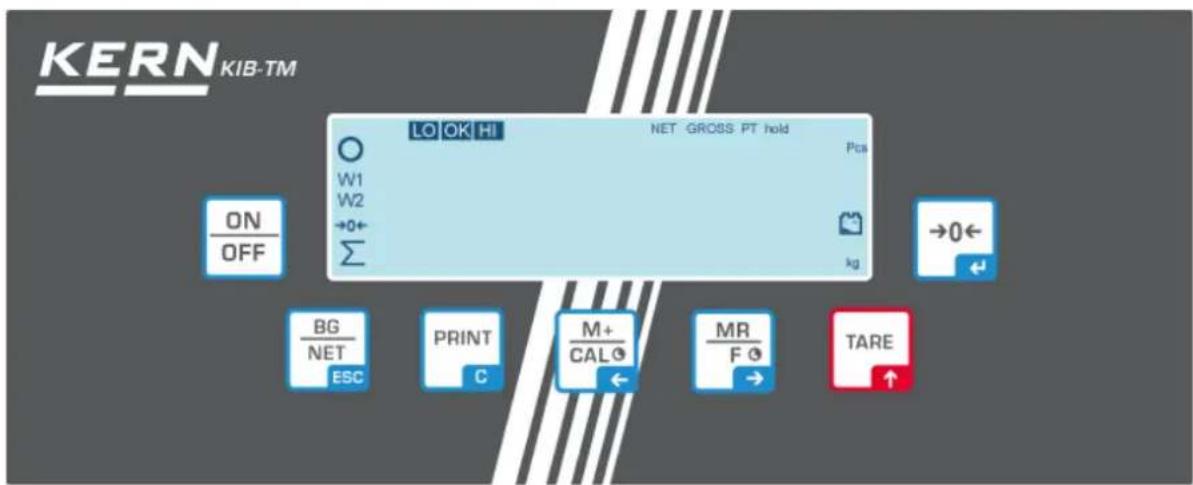
2 Appliance overview
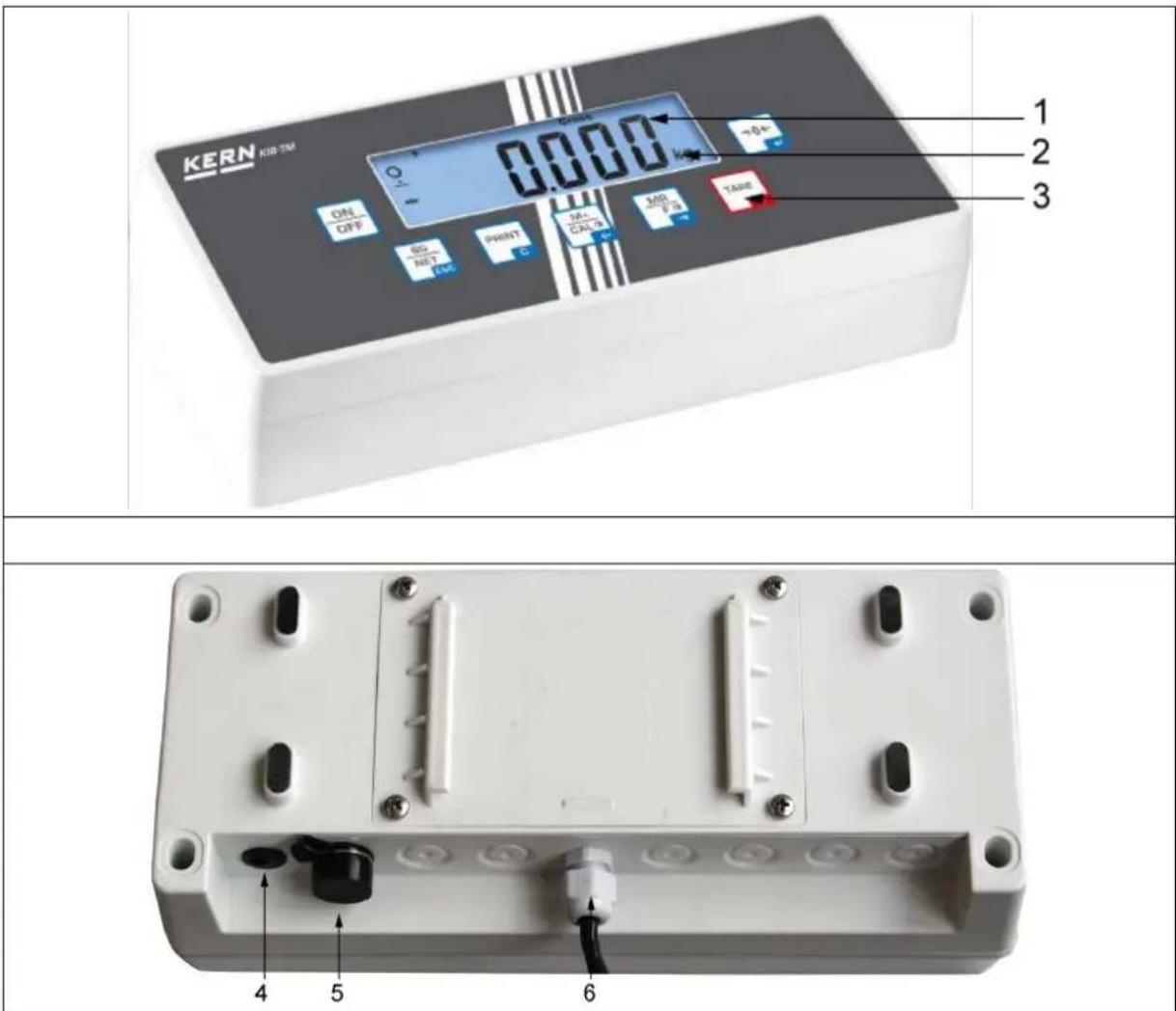
- Weight display
- Weighing unit
- Keyboard
- Connection of mains adapter
- RS232 interface
- Input connection load cell cable
2.1 Keyboard overview
| Button Function | |
 | Turn on/off |
 Navigation button ← Navigation button ← | ZeroingConfirm entry |
 Navigation button ↑ Navigation button ↑ | TaringAt numeric input increase flashing digitScroll forward in menu |
 Navigation button → Navigation button → | Display sum totalDigit selection to the right |
 Navigation button ← Navigation button ← | Add weighing value to summation memoryDigit selection to the left |
 C C | Calculate weighing data via interfaceDelete |
 ESC ESC | Change between gross ⇔ and net weightBack to menu/weighing mode |
 | Call up animal weighing function |
 | Retrieve tolerance weighing |
 | Delete total added memory |
2.1.1 Numeric entry via navigation keys
⇒ Press →0←, the current setting will be displayed. The first digit will be flashing and is ready for changing.
⇒ If you do not wish to change the first digit, press MR F 0 → and the second digit will start flashing.
Each time you press, t display will move to the subsequent digit, after the last digit the display will return to the first digit.
To change the selected (flashing) digit, press repeatedly until the desired value is displayed. Then press to access further digits and change them by TARE
⇒ Complete your entry by 0
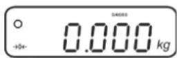
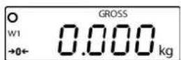
2.2 Overview of display
| Display Significance | |
| W1 Weighing range 1 | |
| W2 Weighing range 2 | |
 | Rechargeable battery very low |
 Stability display Stability display | |
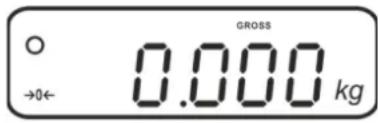
·  - - | Zero indicator |
| GROSS Gross weight | |
| NET Net weight | |
| PT Pre-Tare | |
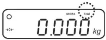
| hold Hold function | |
| Pcs Parts counting | |
| Kg Weighing unit | |
 | Totalization |
| LO OK HI | Indicators for weighing with tolerance range |
3 Basic Information (General)
3.1 Proper use
The display unit acquired by you is used in combination with a weighing plate and serves to determine the weighing value of material to be weighed. It is intended to be used as a “non-automatic weighing system”, i.e. the material to be weighed is manually and carefully placed in the centre of the weighing plate. As soon as a stable weighing value is reached the weighing value can be read.
3.2 Improper Use
Do not use display unit for dynamic weighing. In the event that small quantities are removed or added to the material to be weighed, incorrect weighing results can be displayed due to the “stability compensation” in the display unit. (Example: Slowly draining fluids from a container on the balance.)
Do not leave permanent load on the weighing pan. This may damage the measuring system.
Impacts and overloading exceeding the stated maximum load (max) of the weighing plate, minus a possibly existing tare load, must be strictly avoided. Both, the weighing plate and the display unit may be damaged during this process.
Never operate display unit in explosive environment. The serial version is not explosion protected.
Changes to the display unit's design are not permitted. This may lead to incorrect weighing results, safety-related faults and destruction of the display unit.
The display unit may only be operated in accordance with the described default settings. Other areas of use must be released by KERN in writing.
3.3 Warranty
Warranty claims shall be voided in case
• Our conditions in the operation manual are ignored
- The appliance is used outside the described uses
• The appliance is modified or opened
• Mechanical damage or damage by media, liquids, natural wear and tear
- The appliance is improperly set up or incorrectly electrically connected
• The measuring system is overloaded
3.4 Monitoring of Test Resources
In the framework of quality assurance the measuring-related properties of the display unit and, if applicable, the testing weight, must be checked regularly. The responsible user must define a suitable interval as well as type and scope of this test. Information is available on KERN's home page (www.kern-sohn.com with regard to the monitoring of display units' test substances and the test weights required for this. In KERN's accredited DKD calibration laboratory test weights and display units may be calibrated (return to the national standard) fast and at moderate cost.
4 Basic Safety Precautions
4.1 Pay attention to the instructions in the Operation Manual

→ Carefully read this operation manual before setup and commissioning, even if you are already familiar with KERN balances.
4.2 Personnel training
The appliance may only be operated and maintained by trained personnel.
5 Transport and storage
5.1 Testing upon acceptance
When receiving the appliance, please check packaging immediately, and the appliance itself when unpacking for possible visible damage.
5.2 Packaging / return transport

Keep all parts of the original packaging for a possibly required return.
⇒ Only use original packaging for returning.
Prior to dispatch disconnect all cables and remove loose/mobile parts.
→ Reattach possibly supplied transport securing devices.
⇒ Secure all parts such as the glass wind screen, the weighing platform, power unit etc. against shifting and damage.
6 Unpacking and installation
6.1 Installation Site, Location of Use
The display units are designed in a way that reliable weighing results are achieved in common conditions of use.
Precise and fast work is achieved by selecting the right place for your display unit and your weighing plate.
On the installation site observe the following:
- Place the display unit and the weighing plate on a stable, even surface.
- Avoid extreme heat as well as temperature fluctuation caused by installing next to a radiator or in the direct sunlight;
- Protect the display unit and the weighing plate against direct draft from open windows or doors.
- Avoid jarring during weighing;
- Protect the display unit and the weighing plate against high humidity, vapours and dust.
- Do not expose the display unit to extreme dampness for longer periods of time. Non-permitted condensation (condensation of air humidity on the appliance) may occur if a cold appliance is taken to a considerably warmer environment. In this case, acclimatize the disconnected appliance for ca. 2 hours at room temperature.
- Avoid static charge of goods to be weighed or weighing container.
Major display deviations (incorrect weighing results) may be experienced should electromagnetic fields (e.g. due to mobile phones or radio equipment), static electricity accumulations or instable power supply occur. Change location or remove source of interference.
6.2 Unpacking
Carefully remove the display unit from packaging, remove plastic cover and place it in the designated work area.
and place it in the designated work area.
Mount the display unit in a way that facilitates operation and where it is easy to see.
6.3 Scope of delivery / serial accessories:
- Display Unit
- Mains adapter
- Table leg
- Wall bracket
- Operating manual
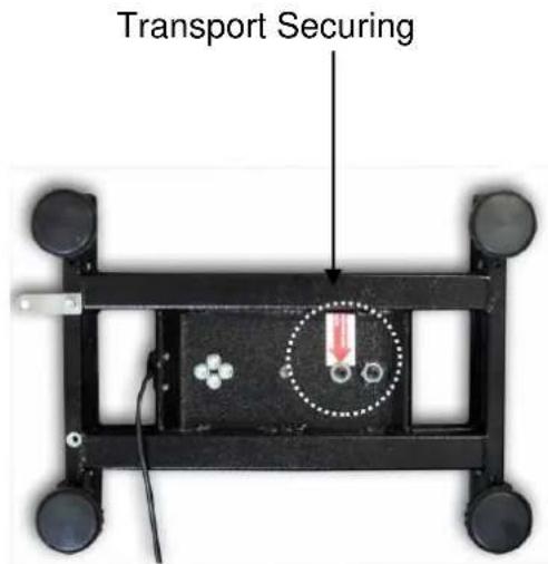
6.4 Transportation lock (illustration example)
Please note: if the display unit is used together with platform with transportation lock, this transportation lock must be released prior to use:
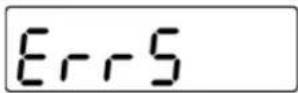
6.5 Error message

As soon as an error message appears in the balance display, the balance must not more be used, e.g. Err 4
6.6 Placing
Mount the display unit in a way that facilitates operation and where it is easy to see.
There are many ways of positioning the display unit, such as free-standing or wall-mounted (optional).
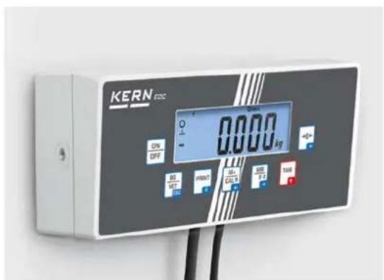
Wall-mounted (optional)
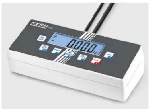
Free standing
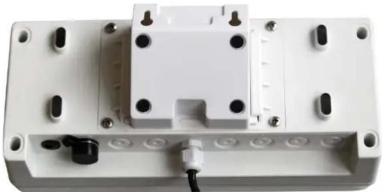
Version with support base/wall bracket
natural_image
White plastic electrical enclosure with mounting holes and a black connector (no visible text or symbols)Version with tripod EOC-A05 (optional)

natural_image
Exterior view of a modern office building (no signage)In order to raise the display, the display unit can be mounted on an optional stand.
Usage with fitting panel EOC-A03 (optional):
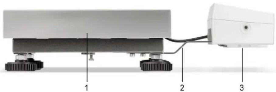
natural_image
Diagram of a robotic platform with three labeled components (1, 2, 3), showing base, wheels, and connected cable (no text or symbols beyond labels)- Platform
- Fitting panel
- Display Unit
6.7 Mains connection

Select a country-specific power plug and insert it in the mains adapter.

Check, whether the voltage acceptance on the scales is set correctly. Do not connect the scales to the power mains unless the information on the scales (sticker) matches the local mains voltage.
Only use KERN original mains adapter. Using other makes requires consent by KERN.

Important:
Before starting your weighing balance, check the mains cable for damage.
➢ Ensure that the power unit does not come into contact with liquids.
▶ Ensure access to mains plug at all times.
6.8 Storage battery operation (optional)
Before the first use, the battery should be charged by connecting it to the mains power supply for at least 12 hours.
If the weight display shows the flashing symbol 📄, this is an indication that the capacity of the rechargeable battery is almost exhausted. Charge the battery with the help of the supplied power pack.
6.9 Adjustment
As the acceleration value due to gravity is not the same at every location on earth, each display unit with connected weighing plate must be coordinated - in compliance with the underlying physical weighing principle - to the existing acceleration due to gravity at its place of location (only if the weighing system has not already been adjusted to the location in the factory). This adjustment process must be carried out for the first commissioning, after each change of location as well as in case of fluctuating environment temperature. To receive accurate measuring values it is also recommended to adjust the display unit periodically in weighing operation.

- Prepare the required adjustment weight. The adjustment weight to be used depends on the capacity of the weighing system. Carry out adjustment as near as possible to the weighing system's maximum weight. Info about test weights can be found on the Internet at: http://www.kern-sohn.com.
- Observe stable environmental conditions. Stabilisation requires a certain warm-up time.
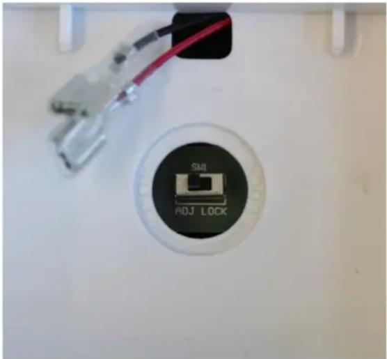
Adjustment switch:
The adjustment switch is located in the battery cartridge(see the photo).
natural_image
Close-up of a white appliance interior with a circular button labeled 'ADJ LOCK' and a red cable, no readable text or symbols beyond the label.Adjustment switch in the "ADJ" setting:
- All menu items are available.
Adjustment switch in the "LOCK" position:
- Some of the menu items are locked (see the section "Menu overview") To unblock these menu items, place the adjustment switch in the "ADJ" position.
Call up menu:
→ Switch-on balance and during the selftest press „Pn“ will be displayed
⇒ Press +CALO , , , subsequently, the first menu block „PO CHK“ will be displayed.
⇒ Press TARE repeatedly until „P3 CAL“ will be displayed.
Acknowledge with 0 . „CoUnt“ is displayed.
⇒ Press TARE repeatedly until „CAL“ will be displayed.
Acknowledge using 0 , the current setting is displayed.
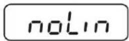
→ Press →0← to select the desired setting and confirm by noLin = adjustment
LineAr = linearization, see chap. 6.10


→ How to carry out adjustment:
→ Confirm menu setting „noLin“ by →0←
Ensure that there are no objects on the weighing plate.
→ Wait for stability display, then press →0←
→ The currently set adjustment weight will be displayed.
Either use adjustment weight displayed or
change with the help of the navigation keys (see chap.2.1.1), the active digit will be flashing.
⇒ Confirm value for adjustment weight by pressing →0←
→ Carefully place adjustment weight in the centre of the weighing plate. Wait for stability display, then press "PASS" will be shown briefly, followed by the weight of the placed adjustment weight.
→ Remove adjustment weight, balance will return into weighing mode automatically. An adjusting error or incorrect adjustment weight will be indicated by the error message; repeat adjustment procedure.

(example)

6.10 Linearization
Linearity shows the greatest deviation of a weight display on the scale to the value of the respective test weight according to plus and minus over the entire weighing range. If linearity deviation is discovered during a monitoring of test resources, you can improve this by means of linearization.

- In balances with a resolution of > 15 000 dividing steps carrying out a linearisation is recommended.
- Carrying out linearization is restricted to specialist staff possessing well acquainted with the workings of weighing scales.
- The test weights to be used must be adapted to the weighing scale's specifications; see chapter "Monitoring of test equipment".
- Observe stable environmental conditions. Stabilisation requires a certain warm-up time.
- After successful linearisation you will have to carry out calibration; see chapter 3.4 "Monitoring of test equipment".
Procedure:
→ Call-up menu item P3 CAL→Cal→Liner, see chap. 6.9
⇒ Confirm by 0 , the password query „Pn“ will be displayed.
⇒ Press , +CALO , subsequently.
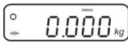
Ensure that there are no objects on the weighing pan.
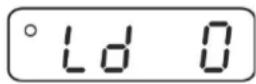
→ Wait for stability display, then press →0←
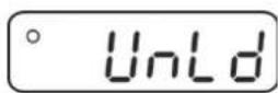
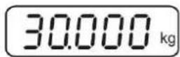
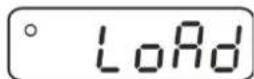
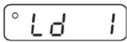
When "Ld 1" is displayed, put the first adjustment weight (1/3 max) carefully in the centre of the weighing platform.
Wait for stability display, then press 0
When "Ld 2" is displayed, put the second adjustment weight (2/3 max) carefully in the centre of the weighing platform.
Wait for stability display, then press →0←
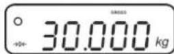
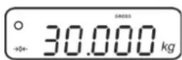
When "Ld 3" is displayed, put the third adjustment weight (max) carefully in the centre of the weighing platform.
Wait for stability display, then press →0←
"PASS" will be shown briefly, followed by the weight of the placed adjustment weight.
→ Remove adjustment weight, balance will return into weighing mode automatically. An adjusting error or incorrect adjustment weight will be indicated by the error message; repeat adjustment procedure.


7 Operation
7.1 Start-up
⇒ Press ON OFF, the appliance will carry out a self-test. As soon as the weight display appears, the instrument will be ready to weigh.
7.2 Switching Off
⇒ Press , the display will disappear.
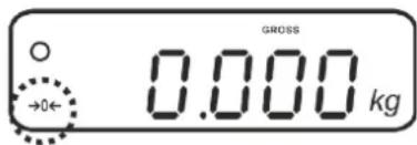
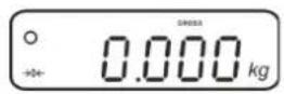
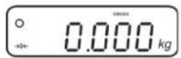
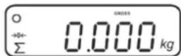
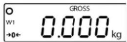
7.3 Zeroing
Resetting to zero corrects the influence of light soiling on the weighing plate. The unit is equipped with an automatic zero setting function. Therefore the unit can be reset to zero at any time as follows:
⇒ To unload the weighing system
⇒ Press 0 and zero display as well as indicator 0 will appear.
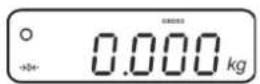
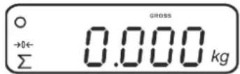
7.4 Simple weighing
→ Place goods to be weighed on balance.
→ Wait for stability display ○
→ Read weighing result.

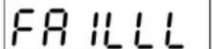
Overload warning
Overloading exceeding the stated maximum load (max) of the device, minus a possibly existing tare load, must be strictly avoided. This could damage the instrument.
Exceeding the maximum load is indicated by the display
HABBABB
and an audio sound. Unload weighing system or reduce preload.
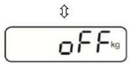
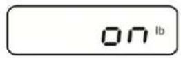
7.5 Switch-over weighing unit
How to enable weighing units:
→ Invoke menu item P5 Unt, see chap. 8
⇒ Press and the first weighing unit with the current setting will be displayed.
To enable [on] / disable [off] the displayed weighing unit, press TARE
Acknowledge with 0 the next unit with the current setting will be displayed.
⇒ To enable [on] / disable [off] the displayed weighing unit, press TARE
→ Acknowledge with →0←
⇒ Repeat sequence for each weighing unit.
Note:
„tj“ and „Hj“ cannot be activated at the same time,
only either ... or ... .
→ Press back to weighing mode BG NET EGC several times.
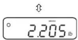
Switch-over weighing unit:
Keep pressed, the display changes over to the weighing units activated before (e.g. kg lb)

7.6 Weighing with tare
⇒ Deposit weighing vessel. After successful standstill control press the button. Zero display and indicator NET appear.
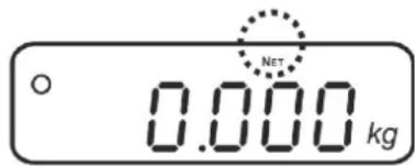
The weight of the container is now internally saved.
→ Weigh the material, the net weight will be indicated.
⇒ The weight of the weighing container will be displayed as a minus number after removing the weighing container.
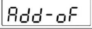
⇒ The tare procedure can be repeated as many times as necessary, for example with initial weighing of several components for a mix (add-on weighing). The limit is reached when the taring range capacity (see type plate) is full.
⇒ To change between gross weight and net weight, press
To delete the tare value, remove load from weighing plate and press
7.6.1 Pre-Tare
It is possible to enter a pre-tare value beforehand.
⇒ Ensure that there are no objects on the weighing pan.
⇒ Press TARE and hold until 0.0 is displayed and the left digit is flashing
⇒ Use the arrow keys to enter the pre-tare value and confirm by pressing The pre-tare value will be shown as a negative value.
7.7 Weighing with tolerance range
You can set an upper or lower limit when weighing with tolerance range and thus ensure that the weighed load remains exactly within the set limits.
During tolerance tests such as dosing, portioning and sorting the unit will indicate exceeded or undershot limits by emitting an optical or acoustic signal.
Audio signal:
The acoustic signal depends on the settings in menu block „BEEP“.
Options:
• no Acoustic signal turned off
- ok An acoustic signal sounds when load is within tolerance limits
- ng An acoustic signal sounds when load is beyond tolerance limits
Optical signal:
The indicators show whether the load is within the two set tolerance limits.
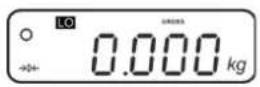
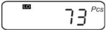
| LO | Target quantity / target weight below minimum tolerance limit |
| OK | Target quantity / target weight within tolerance range |
| HI | Target quantity / target weight exceeds maximum tolerance limit |
The settings for tolerance check may be called up either via menu block „P0 CHK“ (see chap. 8) or faster via the key combination

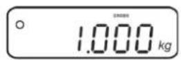
7.7.1 Tolerance check for target weight
Settings
⇒ Press and at the same time in weighing mode.
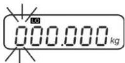
⇒ Press TARE until the display for entering the lower limit value nETL appears.
⇒ Press →0←, the current setting will be displayed.
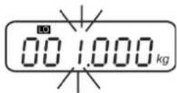
To enter the lower limit, e. g. 1000 Kg, press the navigation keys (See chap. 2.1.1); the currently enabled digit will be flashing.
→ Confirm input by →0←
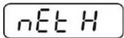
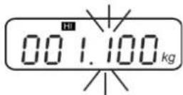
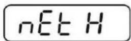
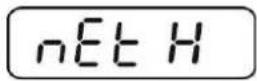
⇒ Press TARE repeatedly until nEt H is displayed.
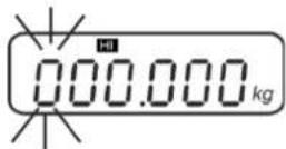
⇒ Press, the current setting for the upper limit will be displayed.
⇒ Press the navigation keys (See chap. 2.1.1) to enter the upper limit, e.g. 1100 kg; the currently enabled digit will be flashing.
→ Confirm input by →0←
⇒ Press TARE repeatedly until BEEP is displayed.
↓


⇒ Press, the current setting for the acoustic signal will be shown.

Select desired setting (no, ok, ng, s. chap. 8) by

→ Confirm input by →0←
⇒ Press : weighing system is in tolerance weighing mode. From here evaluation takes place whether the goods to be weighed are within the two tolerance limits.
Weighing with tolerance range
⇒ Tare when using a weighing container.
Put on goods to be weighed, tolerance control is started. The signal lights indicate whether the load is within the two set limits.
| Load below specified tolerance | Load within specified tolerance | Load exceeds specified tolerance |
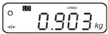 IndicatorLQbe displayed IndicatorLQbe displayed | 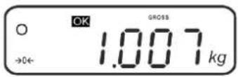 IndicatorCKbe displayed IndicatorCKbe displayed | 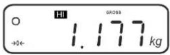 IndicatorHfbe displayed IndicatorHfbe displayed |

- The tolerance control is not active when the weight is under 20d. - To delete limits, enter "00.000 kg".
7.7.2 Tolerance check for target quantity
Settings
⇒ Press and at the same time in weighing mode.
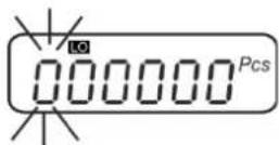
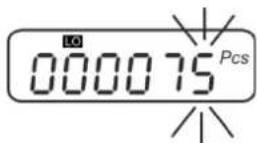
⇒ Press TARE until the display for entering the lower limit value PCSL appears.
⇒ Press →0←, the current setting will be displayed.
To enter the lower limit, e. g. 75 items, press the navigation buttons (see chap. 2.1.1); the currently enabled digit will be flashing.
→ Confirm input by →0←
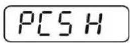
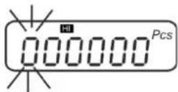
⇒ Press TARE repeatedly until PCS H is displayed.
⇒ Press, the current setting for the upper limit will be displayed.
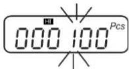
To enter the upper limit, e. g. 100 items, press the navigation buttons (see chap. 2.1.1); the currently enabled digit will be flashing.
→ Confirm input by →0←
⇒ Press TARE repeatedly until bEEP is displayed.

↓


⇒ Press, the current setting for the acoustic signal will be shown.

Select desired setting (no, ok, ng, s. chap. 8) by TARE

→ Confirm input by →0←
⇒ Press : weighing system is in tolerance weighing mode. From here evaluation takes place whether the goods to be weighed are within the two tolerance limits.
Weighing with tolerance range
→ Set item weight, see chap. 7.10.
→ Tare when using a weighing container.
Put on goods to be weighed, tolerance control is started. The signal lights indicate whether the load is within the two set limits.
| Load below specified tolerance | Load within specified tolerance | Load exceeds specified tolerance |
 IndicatorLQbe displayed IndicatorLQbe displayed | 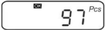 IndicatorCKbe displayed IndicatorCKbe displayed | 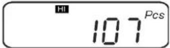 IndicatorHfbe displayed IndicatorHfbe displayed |

- The tolerance control is not active when the weight is under 20d.
• To delete limits, enter „00000 PCS“.
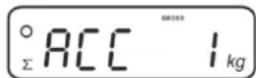
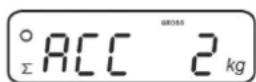
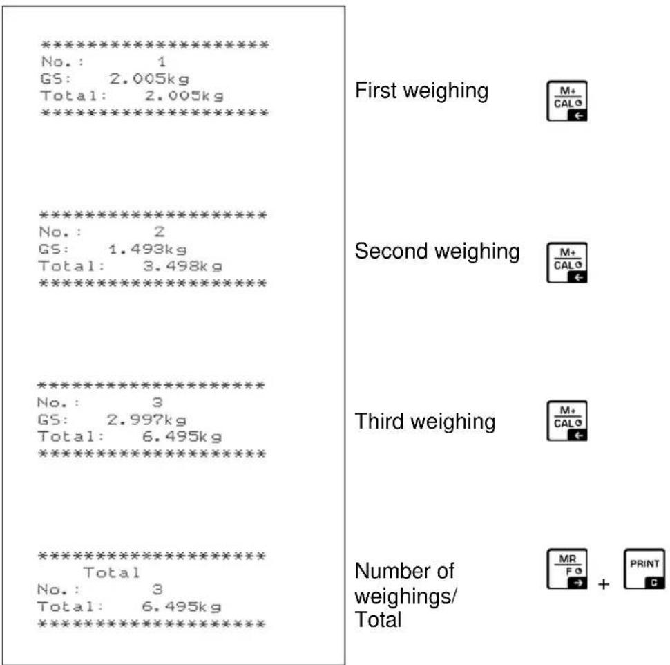
7.8 Manual totalizing
With this function the individual weighing values are added into the summation memory by pressing + and edited, when an optional printer is connected.

- Menu setting:
„P2 COM“ ⇒ „MODE“ ⇒ „PR2“, see chap. 8 - The totalizing function is not active when the weight is under 20d.
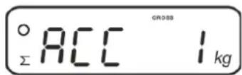
Add up:
→ Place load A.
Wait until the stability display ○ appears, then press M+ CALG. The weight value will be saved and printed if an optional printer is connected.
→ Remove the weighed good. More weighed goods can only be added when the display ≤ zero.
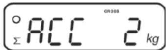
→ Place good to be weighed B.
Wait until the stability display appears, then press the weight value will be added to the summation memory and printed, as required. The number of weighings, the whole weight and the currently placed weight will be shown in succession.
→ Add more weighed goods as described before.
Please note that the weighing system must be unloaded between the individual weighing procedures.
This process may be repeated 99 times or till such time as the capacity of the weighing system has been exhausted.
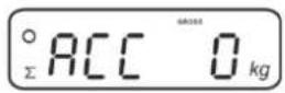
Display and edit sum „Total“:
⇒ Press MR F 0, the number of weighings, followed by the total weight will be displayed for 2 sec. Press PRINT to print out this display.
Delete weighing data:
⇒ Press +CALO and at the same time The data in the summation memory are deleted.
Sample log (KERN YKB-01N):
Menu setting "P2 COM" "Lab 2" / Prt 4 - 7"

For additional sample logs see chap. 0
7.9 Automatic adding-up
With this function the individual weighing values are automatically added into the summation memory when the balance is unloaded without pressing ____ edited, when an optional printer is connected.
- Menu settings:
Indicator will be displayed.

Add up:
→ Place load A.
After the standstill control sounds a signal tone. The weighing value will be added to the summation memory and printed.
→ Remove the weighed good. More weighed goods can only be added when the display ≤ zero.
→ Place good to be weighed B.
After the standstill control sounds a signal tone. The weighing value will be added to the summation memory and printed, as required. The number of weighings, followed by the currently placed weight will be shown in succession.
→ Add more weighed goods as described before.
Please note that the weighing system must be unloaded between the individual weighing procedures.
⇒ This process may be repeated 99 times or till such time as the capacity of the weighing system has been exhausted.

For how to display and delete weighing data as well as sample logs see chap. 7.8
7.10 Parts counting
Before the balance can count parts, it must know the average part weight (i.e. reference). Proceed by putting on a certain number of the parts to be counted. The balance determines the total weight and divides it by the number of parts, the so-called reference quantity. Counting is then carried out on the basis of the calculated average piece weight.
As a rule:
The higher the reference quantity the higher the counting exactness.
⇒ In weighing mode MR F0, press and hold until the message „P 10“ appears that is used to set the reference quantity.
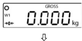
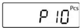
⇒ Use TARE to set the desired reference quantity (such as 100), options include P 10, P 20, P 50, P100, P 200.
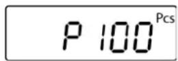
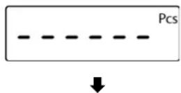
Place as many items to be counted (such as 100 items) as demanded by the set reference quantity and confirm by The weighing scales calculate the reference weight. The current quantity (such as 100 items) will be displayed.
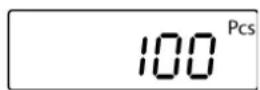
→ Remove reference weight. The balance is from now in parts counting mode counting all units on the weighing plate.
→ Back to Weighing mode by MR F 3
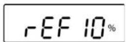
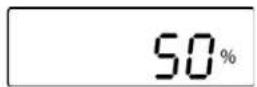
7.11 Percent weighing
Percentage weighing allows you to display the weight in percent related to reference weight.
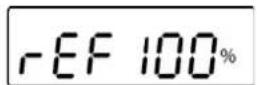
⇒ Press TARE in weighing mode (approx. 3 sec.) until "rEF 10%" is displayed.
⇒ Use TARE to set the desired percentage value to be applied as reference (selectable rEF 10, rEF 20, rEF 50, rEF 100, rEF 200, rEF 500).
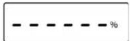
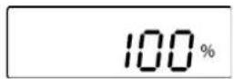
Place a sample matching the set percentage value on the weighing platform and press 0 “----%” will be briefly displayed.
→ The percentage value for the sample will be displayed.
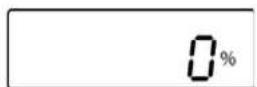
→ Remove reference weight
⇒ The display returns to „0.0 %“
→ Put on specimen
In the display appears the percentage of the specimen with reference to the reference weight.
⇒ Back to weighing mode by pressing the TARE button.
7.12 Animal weighing
The animal weighing function is suitable for weighing restless loads.
The weighing system will display a mean value derived from several weighing results.
The animal weighing program can be enabled by either calling up menu block
„P4 OTH“ ⇒ „ANM“ ⇒ „ON“ (see chap. 8) or faster via key combination.

The indicator shows HOLD as long as the animal weighing function remains enabled.
→ Place the load on the weighing system and wait until the scale is steady.
⇒ Press TARE and →0← at the same time; you will hear an acoustic signal, indicating that the mean value function is enabled.
Whilst averaging is taking place you can add or remove loads as the measuring value will be constantly updated.
⇒ To deactivate the animal weighing function press TARE and →0← at the same time.
7.13 Lock keyboard
In the menu item „P4 OTH“ ⇒ „LOCK“ (see chap. 8) the keyboard lock can be enabled/disabled.
Whilst the function is enabled the keyboard will self-lock after no key has been pressed for 10 minutes. „K-LCK“ will be displayed as soon as a key is pressed.

To disable the lock, keep PRINT, MR and 0 pressed at the same time (2 s) until "U LCK" appears.
7.14 Display background illumination
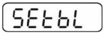
⇒ Keep 0 pressed (3s) until „setbl“ appears.
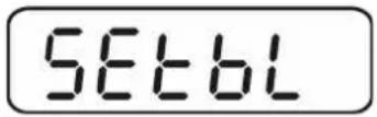
⇒ Press 0 again, the current setting will be displayed.
⇒ Press TARE to select the desired setting.
bl on Continuous background lighting
bl off Background illumination off
bl Auto Automatic background illumination on when weighing pate is loaded or key pressed.
⇒ Either save by 0 or cancel input by pressing ESC. Back to Weighing mode by ESC
7.15 Automatic switch-off function „AUTO OFF“
The unit is automatically switched off within the preset time when the display unit or the weighing bridge are not operated.
→ Keep →0← pressed (3s) until „setbl“ appears.
→ Press TARE to call up AUTO OFF-function
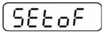
⇒ Press 0 , the current setting will be displayed.
⇒ Press TARE to select the desired setting.
of 0 Function deactivated
of 3 Weighing system will be turned off after 3 min.
of 5 Weighing system will be turned off after 5 min.
of 15 Weighing system will be turned off after 15 min.
of 30 Weighing system will be turned off after 30 min.
⇒ Either save by 0 or cancel input by pressing Esc Back to Weighing mode by , Esc
7.16 Setting time and date
To change date and time go to menu item "P8 ind" "dAtE" or "tIME"
(See chap. 8):
Setting date:
→ Select menu item "dAtE"
⇒ Press →0← to confirm and the last date entered will be displayed. The first digit is flashing
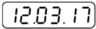
(example)
Use the navigation keys, as described in chap. 2.1.1, to enter the current date and press 0 to confirm.
The current date will be shown in standby mode.
Setting time:
→ Select menu item "tiME"
⇒ Press →0← to confirm and the last time entered will be shown. The first digit is flashing.
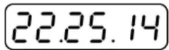
(example)
Use the navigation keys, as described in chap. 2.1.1, to enter the current time and press 0 confirm.
The time will be shown in standby mode.
7.17 Alphabet
Letters are ordered in the following order:
| A | B | b | C | D | E | F | G | H | h | I | J | K | L |
| I | M | N | O | P | Q | R | S | U | V | W | X | Y | Z |
8 Menu
8.1 Navigation in the menu:
| Call up menu | Switch-on balance and during the selftest press  Press, subsequently, the first menu block „PO CHK“ will be displayed. Press, subsequently, the first menu block „PO CHK“ will be displayed. |
| From the weighing mode:Press and hold until Pn appears.Z278]Enter the password (see above.) | |
| Select menu block | With help of, the individual menu items can be selected one after the other. |
| Select setting | Confirm select  g The current setting will be displayed. g The current setting will be displayed. |
| Change settings | To change to the available settings, press the navigations keys as described in chap. 2.1.1. |
| Acknowledge setting / exit the menu | Either save by  I by pressing I by pressing . . |
| Return to weighing mode | Press repeatedly to exit menu. |
8.2 Menu overview
| Menu blockMain menu | Menu item Submenu | Available settings / explanation | ||
| PO CHKWeighing with tolerance range, see chap. 7.7 | nEt H | Upper limit value „Tolerance check weighing“, input see chap. 7.7.1 | ||
| nEt L | Lower limit value „Tolerance check weighing“, input see chap. 7.7.1 | |||
| PCS H | Upper limit value „Tolerance check counting“, input see chap. 7.7.2 | |||
| PCS L | Lower limit value „Tolerance check counting“, input see chap. 7.7.2 | |||
| BEEP no | Acoustic signal for weighing with tolerance range switched off | |||
| ok | Audio sound when weighed load is within tolerance limits | |||
| nG | Audio sound when weighed load is beyond tolerance limits | |||
| rELAY on | Relay pilot light | |||
| oFF | ||||
| P1 rEF1Zero point settings | A2n0 | Automatic zero point correction (Autozero) by changing the display, digits selectable (0, 0.5d, 1d, 2d, 4d) | ||
| 0AUto Zero setting rangeLoad range where the display after switching-on the balance is set to zero. Selectable 0, 2, 5, 10, 20, 30, 50, 100 % | ||||
0rAGE Zero setting rangeLoad range where the display is set to zero by pressing  . Selectable 0, 2, 4, 10, 20*, 50, 100%. . Selectable 0, 2, 4, 10, 20*, 50, 100%. | ||||
| 0tArE | Automatic taring „on / off“, taring range adjustable in menu item „0Auto“. | |||
| P2 COMInterface parameter | MODE | CONT | S0 off | Continuous data output, selectable „sending 0“, yes / no |
| S0 on | ||||
| ST1 | One output for stable weighing value | |||
| STC | Continuous data output of stable weighing values | |||
| PR1 | Output after pressing  Precondition for alibi memory Precondition for alibi memory | |||
| PR2 | Manual totalizing, see chap. 7.8Press  and the weighing value will be added to the summation memory and issued. and the weighing value will be added to the summation memory and issued. | |||
| AUTO* | For automatic totalizing see chap. 7.9This function is used to issue and add individual weighing values automatically to the summation memory on unloading of weighing scale. | |||
| ASK | Remote control instructions | |||
| wirel | Not documented | |||
| BAUD | Available | Baudrate: 600, 1200, 2400, 4800, 9600* | ||
| Pr | 7E1 | 7 bits, even parity | ||
| 7o1 | 7 bits, odd parity | |||
| 8n1* | 8 bits, no parity | |||
| PTYPE | tPUP* | Standard printer setting | ||
| LP50 | Not documented | |||
| KCP | KERN Communication Protocol | |||
| LAb | LAb x | For data output format,see table below. 1 | ||
| Prt | Prt x | |||
| LAnG | eng* | Standard settings English | ||
| chn | Not documented | |||
| P3 CAL ^1 Configurationdatasee chap. 12.4 | COUNT | Display internal resolution | ||
| DECI | Position of the decimal dot | |||
| DUAL | Setting balance type, capacity (Max) and readability (d) | |||
| off | Single-range balance | |||
| R1 inc | Readability | |||
| R1 cap | Capacity | |||
| on | Dual range balance | |||
| R1 inc | Readability 1st weighing range | |||
| R1 cap | Capacity 1st weighing range | |||
 | ||||
| R2 inc | Readability 2nd weighing range | |||
| R2 cap | Capacity 2nd weighing range | |||
| CAL | noLin | For adjustment, see chap. 6.9.2 | ||
| Liner | For linearization, see chap. 6.10.2 | |||
| GrA | Gravitational constant at place of installation | |||
| GrB | Gravitational constant at place of manufacture | |||
| P4 OTH | LOCK | on | Keyboard lock enabled, see chap. 7.13 | |
| off* | Keyboard lock disabled | |||
| ANM ^1 | on | Animal weighing enabled, see chap. 7.12 | ||
| off* | Animal weighing disabled | |||
| SCr | on | watch as screensaver enabled | ||
| off* | watch as screensaver disabled | |||
| P5 Unt ^1 Change weighing unitsee chap. 7.5 | kg | on* | ||
| off | ||||
| g | on | |||
| off* | ||||
| lb | on | |||
| off* | ||||
| oz | on | |||
| off* | ||||
| tJ | on | |||
| off | ||||
| HJ | on | |||
| off | ||||
| P6 xcl ^1 | Not documented | |||
| P7 rst ^1 Factory setting | Use  to reset balance settings to factory default. to reset balance settings to factory default. | |||
| P8 ind | dAtE | Setting date: Format: TTMMJJ | ||
| tIME | Setting time: Format: HHMMSS | |||
| ALibi | Alibi memory | |||
| dAtA | Number of saved records | |||
| rdAtA | Read the record value | |||
| ErASE | Delete all data | |||
| ExPT | Export data (USB stick) | |||
| PrEt | Enter pre-tare value | |||
| P9 Prt | 485 | ModE | 2disP, Count | Export mode (2nd display) |
| bAUd | 600, 1200, 2400, 4800, 9600 | Baud rate | ||
| Pr | 7o1 | 7 Bit, odd Parity, 1 Stop bit | ||
| 7E1 | 7 Bit, equal Parity, 1 Stop bit | |||
| 8n1 | 8 Bit, no Parity, 1 Stop bit | |||
| io | i_tSt | Test input | ||
| o_tSt | Test output | |||
| oPt | intF | USB, UdiSK, Bt, WiFi, EnEt | Select connections | |
| ModE (output) | no, CoUnt (USB, Bt, Wi-Fi, EnEt) no, Expt (UdiSK) | |||
| iP_1 | IP addresses KIB-TM | |||
| iP_2 | ||||
| iP_3 | ||||
| iP_4 | ||||
| MASK_1 | Subnet mask | |||
| MASK_2 | ||||
| MASK_3 | ||||
| MASK_4 | ||||
| GAtE_1 | KIB-TM Gateway | |||
| GAtE_2 | ||||
| GAtE_3 | ||||
| GAtE_4 | ||||
Continuation menu item P9 Prt
| P9 Prt | oPt | riP_1 | remote (IP-Adresse PC) | |
| riP_2 | ||||
| riP_3 | ||||
| riP_4 | ||||
| rPort | Remote port (Port for communication between PC and KIB-TM | |||
| SSid_1 | SSID | |||
| SSid_2 | ||||
| PSW_1 | WLAN Password | |||
| PSW_2 |
Factory settings are marked by \*.
^1 Function blocked when the adjustment switch is in the position “balance is calibratable” (adjustment switch in the “LOCK” position).
Tab. 1.: Sample logs
- Menu setting P2 Com → Mode → PR2
• Data output after pressing of

| LabPrt | 0 1 2 3 | |||
| 0~3 | **********GS: 5,000kg********** | **********NT: 5,000kgTW: 5,000kgGW: 10,000kg********** | **********GS: 5,000kgTOTAL: 10,000kg********** | **********NT: 5,000kgTW: 5,000kgGW: 10,000kgTotal: 10,000kg********** |
| 4~7 | **********No.: 1GS: 5,000kg********** | **********No.: 1NT: 5,000kgTW: 5,000kgGW: 10,000kg********** | **********No.: 1GS: 5,000kgTotal: 10,000kg********** | **********No.: 1NT: 5,000kgTW: 5,000kgGW: 10,000kgTotal: 10,000kg********** |
| GS Gross weight | |
| NT Net weight | |
| TW Tare weight | |
| NO | Number weighing processes |
| Total | Total of all individual weighings |
9 Servicing, maintenance, disposal
9.1 Cleaning
- Before cleaning, disconnect the appliance from the operating voltage.
- Do not use aggressive detergents (solvents or similar).
9.2 Servicing, maintenance
The appliance may only be opened by trained service technicians who are authorized by KERN.
Before opening, disconnect from power supply.
9.3 Disposal
Disposal of packaging and appliance must be carried out by operator according to valid national or regional law of the location where the appliance is used.
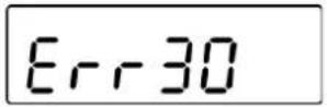
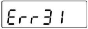
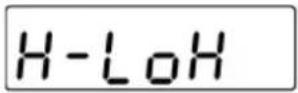
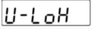
9.4 Error messages
| Error message | Description |
 | Excess load if weight exceeds capacity of +9d |
 | Underweight (less than 20 d) |
 | The weight is too low (less than -20 d) |
 | Zero setting range exceeded on start-up of balance. |
 | Zero setting range during start-up of weighing scale or on pressing of exceeded. |
 | Incorrectly connected verification plug |
 | Is displayed on setting weighing scale to zero with, without load |
 | For parts counting and percentage calculation:Weighed value ≤ zero |
 | For add-up:Total number of weighings above 999 |
 | For add-up:Total weight above 999999 |
 | Adjustment failed |
 | Keyboard locked |
 | Keyboard unlocked |
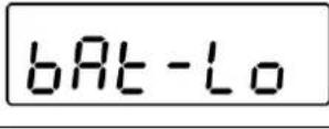 | Capacity of batteries exhausted.(Battery voltage below 5.7 V, automatic shutdown happens at less than 5.4 V) |
Should other error messages occur, switch balance off and then on again. If the error message remains inform manufacturer.
10 RS 232 interface
You can print weighing data automatically via the RS 232C interface or manually by pressing PRINT via the interface according to the setting in the menu.
This data exchange is asynchronous using ASCII - Code.
The following conditions must be met to provide successful communication between the weighing system and the printer.
- Use a suitable cable to connect the display unit to the interface of the printer. Faultless operation requires an adequate KERN interface cable.
- Communication parameters (baud rate, bits and parity) of display unit and printer must match. For a detailed description of interface parameters, please refer to chapter 8, Menu block "P2 COM"
10.1 Technical data
| Connection | 4 pin d-subminiature bushing | |||
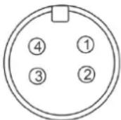 | Pin1 | RX | Input | |
| Pin2 | TX | Output | ||
| Pin3 | GND | Signal ground | ||
| Pin4 | N/C | Not connected | ||
| Baud rate | Optional 600/1200/2400/4800/9600 | |||
| Parity | 8 bits, no parity / 7 bits, even parity / 7 bits, odd parity | |||
10.2 Printer operation / sample logs (KERN YKB-01N)
- Weighing
- Continuous data output (menu setting P2 Com ➔ Mode ➔ Com ➔ S0 on)
Menu setting P2 Com → LAb 0 / Prt 0:
******************************************************************************************
ST, GS
53.2 kg
****************************************************************************************
US, GS
53.2 kg
- Data output after pressing of

(menu settings: P2 Com → Mode → Pr1,
Changes to the menu settings Lab and Prt do not affect the layout of the sample log)
Menu setting P2 Com → LAb 0 / Prt 0\~3 or LAb 3 / Prt 4\~7:
****************************************************************************************
ST, GS
53.2 kg
****************************************************************************************
ST, NT : 52.6 kg
**********************************************************************
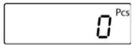
- Counting
****************************************************************************************
PCS
100
****************************************************************************************
- Totalization
- Data output after pressing of M+ CAL9 (menu setting P2 Com → Mode → Pr2)
P2 Com LAb 3 / Prt 4\~7:
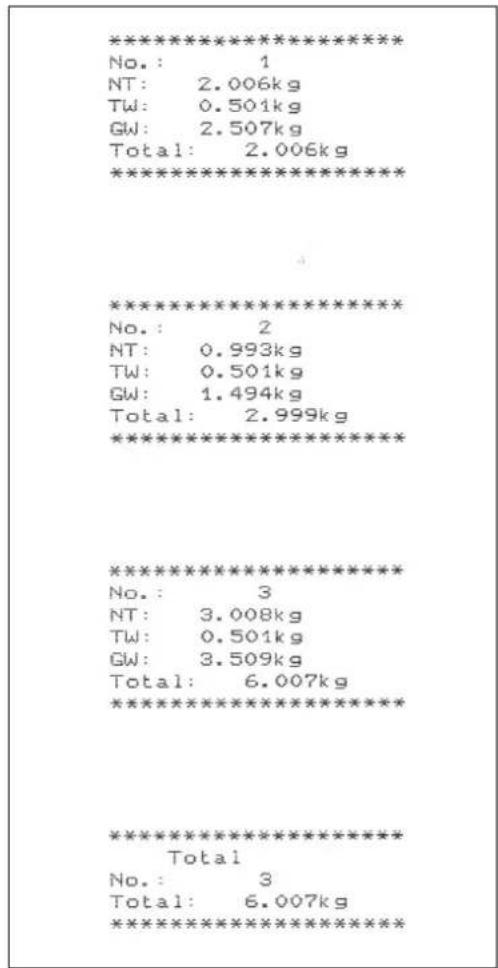
Menu setting P2 Com → LAb 0 / Prt 0:
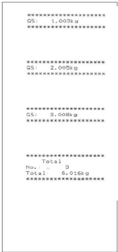
Symbols:
| ST | Stable value |
| US | Instable value |
| GS / GW | Gross weight |
| NT | Net weight |
| TW | Tare weight |
| NO | Number weighing processes |
| TOTAL | Total of all individual weighings |
| <lf> | Space line |
| <lf> | Space line |
10.3 Output log (continuous output)
- Weighing

HEADER1: ST=STABLE, US=UNSTABLE
HEADER2: NT=NET, GS=GROSS

Menu setting: P2 Com→PTYPE → tPUP or LP50
10.4 KERN Communications Protocol (KERN Interface Protocol)
KCP (KERN communication protocol) contains the commands that are used to control the KERN balances via the interface.

- Menu setting P2 Com → Mode → ASK
- Menu setting P2 Com PTYPE KCP
- Finish commands with CR/LF character.
- Consult the KCP manual for more information, available on our KERN website (www.kern-sohn.com).
The following commands are supported:
| @ Cancel | |
| I0 | List all implemented KCP commands |
| I1 | Query KCP level and KCP versions |
| I2 | Query device information (type, capacity) |
| I3 | Query device software version |
| I4 | Query serial number |
| I4_A_"xxxxxxxxx" | Set serial number (default value is K123456) |
| I5 | Query SW-Identification number |
| S | Send stable weight value |
| SI | Send weight value immediately |
| SIR | Send weight value immediately and repeat |
| Z | Zero |
| ZI | Zero immediately |
| D | Display: Write text to display |
| D_“_” | Clear Display (after D-Command) |
| DW | Display: Show weight |
| K | Keys: Set configuration |
| SR | Send weight value on weight change (send and repeat) |
| T | Tare |
| MM | Query/preset tare weight value |
| TAC | Clear tare value |
| TI | Tare immediately |

Polling-Intervall
- The time between periodic inquiries or when sending requests (queries) by the interface must be longer than 100 ms.
11 Instant help
In case of an error in the program process, briefly turn off the display unit and disconnect from power supply. The weighing process must then be restarted from the beginning.
Help:
Fault Possible cause
The displayed weight does not glow.
- The display unit is not switched on.
- Mains power supply interrupted (mains cable defective).
• Power supply interrupted. - (Rechargeable) batteries are inserted incorrectly or empty
- No (rechargeable) batteries inserted.
The displayed weight is permanently changing
- Draught/air movement
- Table/floor vibrations
- Weighing pan has contact with other objects.
- Electromagnetic fields / static charging (choose different location/switch off interfering device if possible)
The weighing result is obviously incorrect
• The display of the balance is not at zero
- Adjustment is no longer correct.
• Great fluctuations in temperature.
• Warm-up time was ignored.
- Electromagnetic fields / static charging (choose different location/switch off interfering device if possible)
Should other error messages occur, switch display unit off and then on again. If the error message remains inform manufacturer.
12 Installing display unit / weighing bridge

- Installation / configuration of a weighing system must be carried out by a well acquainted specialist with the workings of weighing balances.
12.1 Technical data
| Supply voltage 12 V / 1000mA | |
| Max. signal voltage 5V | |
| Zeroing range 0-2mV | |
| Sensitivity ≥ 0.15uV/d | |
| Resistance parameter | 87 - 1100 Ω |
12.2 Weighing system design
The display unit is suitable for connection to any analogue load cell in compliance with the required specifications.
The following data must be established before selecting a load cell:
- Weighing balance capacity
This usually corresponds to the heaviest load to be weighed.
- Preload
This corresponds to the total weight of all parts that are to be placed on the weighing cell such as upper part of platform, weighing pan etc.
• Total zero setting range
This is composed of the start-up zero setting range ( ± 2%) and the zero setting range available to the user via the ZERO-key (2%). The total zero setting range equals therefore 4 % of the scale's capacity.
The addition of weighing scales capacity, preload and the total zero setting range give the required capacity for the weighing cell.
To avoid overloading of the weighing cell, include an additional safety margin.
- Smallest desired display division
12.3 How to connect the platform
→ Disconnect the display unit from the power supply.
Solder the individual wires of the load cell cable to the printed circuit board (See fig.).
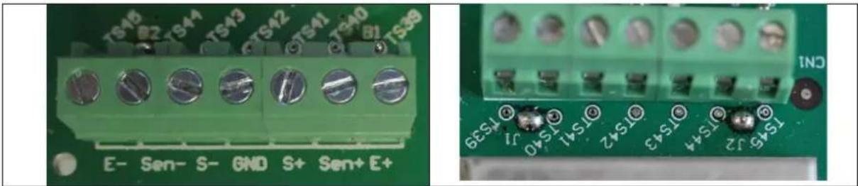
natural_image
Close-up of a green electronic circuit board with terminal connectors and pin labels (no readable text or symbols beyond component markings)
In 4-wire load cells or connection boxes (junction boxes), bridge the solder joints J1 and J2.
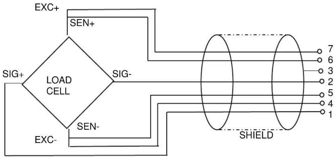
flowchart
graph TD
    A["LOAD CELL"] --> B["EXC+"]
    A --> C["SEN+"]
    A --> D["EXC-"]
    A --> E["SIG+"]
    A --> F["SIG-"]
    A --> G["SIGN-"]
    H["SHIELD"] --> I["7"]
    H --> J["6"]
    H --> K["3"]
    H --> L["2"]
    H --> M["5"]
    H --> N["4"]
    H --> O["1"]
12.4 Configure display unit
+ For menu overview see chap. 8.
| Call up menu:→ Switch-on balance and during the selftest pressM+CALO„Pn“ will be displayed |  |
| → PressM+CALO,BGNETTARE,subsequently, the first menu block „PO CHK“ will be displayed. |  |
| → PressTARErepeatedly until „P3 CAL“ will be displayed. |  |
| → Acknowledge with→0←, „CoUnt“ is displayed. |  |
| Navigation in the menu→ With help ofTARE, the individual menu items can be selected one after the other.→ Confirm selected menu item by pressing→0←the current setting will be displayed.→ To change to the available settings, press the navigations keys as described in chap. 2.1.1.→ Either save by pressing→0←or reject by pressingBGNETESC.→ PressBGNETREpeatedly to exit menu. | |
| Parameter selection1. Display internal resolution→ Press→0←, the internal resolution will be shown.→ Return to menu byBGNETESC→ UseTAREto select another menu item. |    |
| 2. Position decimal point⇒ Press →0←, the currently set position of the decimal dot is displayed.Press TARE to select the desired setting. Selectable 0, 0.0, 0.00, 0.000, 0.0000.Confirm input by →0←⇒ Use TARE to select another menu item. |    |
| 3. Weighing scales type, capacity and readability⇒ Press →0←, the current setting will be displayed.⇒ Select desired setting by TARE„off“ Single-range balance„on“ Dual range balance⇒ Press to confirm, the display for entering readability (for dual range scales for the first weighing range) appears.⇒ Press →0←, the current setting will be displayed.⇒ Select desired setting withTAREand acknowledge by→0↔ |   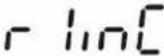  |
| ⇒ PressTARE, the display for entering capacity will appear (at dual range balance for the first range). |  |
| ⇒ Press→0←, the current setting will be displayed. | 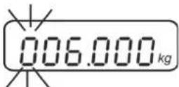 |
| ⇒ Using the navigation buttons (see chap. 2.1.1) select the desired setting, the active digit is flashing. |  |
| ⇒ Acknowledge with→0←In a single-range balancethe entry of capacity / readability is finished. | |
| either in single-range balance | |
| ⇒ PressBGNET, the unit will return to the menu PressTAREto call up next menu item „CAL“. | |
| or | |
| In a dual range balance enter readability and capacity of the second weighing range. | |
| ⇒ PressTARE, the display for entering the readability of the second weighing range will appear. |  |
| ⇒ Press→0←, the current setting will be displayed. |  |
| ⇒ Select desired setting withTAREand acknowledge by→0← |  |
| →Press [TARE], the display for entering the capacity of the second weighing range will appear. |  |
| →Press →0←, the current setting will be displayed. | 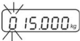 |
| →Using the navigation buttons (see chap. 2.1.1) select the desired setting, the active digit is flashing. |  |
| →Confirm input by →0← | |
| →Press BG/NET ESC, the unit will return to the menu |  |
| →Press TARE to call up next menu item „CAL“. | |
| 4. Adjustment or linearisationAdjustment or linearisation is required after entering configuration data.For carrying out adjustment see chap. 6.9 step 4 or chap. 6.10 for linearisation |  |
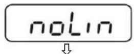
| →Acknowledge using →0←, the current setting is displayed. | 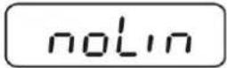 ↓↑ ↓↑ |
| →Press →0← to confirm, press TARE to select the desired setting noLin = AdjustmentLineAr = Linearisation |  |
13 Conformity explanation/ test certificate
The current EC/EU Conformity declaration can be found online in:


KERN KIB-TM
Version 1.2 2019-01
natural_image
White electrical enclosure with multiple mounting holes and a central connector (no visible text or symbols)natural_image
Exterior view of a modern office building (no signage)natural_image
Diagram of a robotic device with three labeled parts (1, 2, 3) showing base, wheels, and connected cable (no text or symbols beyond labels)natural_image
Close-up of a white appliance panel with a circular switch labeled 'SHI' and 'ADJ LOCK', connected to a cable (no additional text or symbols visible)Avertissement surcharge
| A | B | b | C | D | E | F | G | H | h | I | J | K | L |
| I | M | N | O | P | Q | R | S | U | V | W | X | Y | Z |
8 Menu
HEADER2: NT=NET, GS=GROSS

- Réglage du menu P2 Com PTYPE tPUP ou LP50
10.4 KERN Communications Protocol (KERN protocole d'interface)
| @ Cancel | |
| I0 | List all implemented KCP commands |
| I1 | Query KCP level and KCP versions |
| I2 | Query device information (type, capacity) |
| I3 | Query device software version |
| I4 | Query serial number |
| I4_A_"xxxxxxxx" | Set serial number (default value is K123456) |
| I5 | Query SW-Identification number |
| S | Send stable weight value |
| SI | Send weight value immediately |
| SIR | Send weight value immediately and repeat |
| Z | Zero |
| ZI | Zero immediately |
| D | Display: Write text to display |
| D_“_” | Clear Display (after D-Command) |
| DW | Display: Show weight |
| K | Keys: Set configuration |
| SR | Send weight value on weight change (send and repeat) |
| T | Tare |
| TA | Query/preset tare weight value |
| TAC | Clear tare value |
| TI | Tare immediately |

natural_image
Close-up of a green electronic circuit board with terminal connectors and pin labels (no readable text beyond component markings)