GC-PC 1535 I TC - Saw EINHELL - Free user manual and instructions
Find the device manual for free GC-PC 1535 I TC EINHELL in PDF.

User questions about GC-PC 1535 I TC EINHELL
0 question about this device. Answer the ones you know or ask your own.
Ask a new question about this device
Download the instructions for your Saw in PDF format for free! Find your manual GC-PC 1535 I TC - EINHELL and take your electronic device back in hand. On this page are published all the documents necessary for the use of your device. GC-PC 1535 I TC by EINHELL.
USER MANUAL GC-PC 1535 I TC EINHELL
GB Original operating instructions Petrol Chainsaw
natural_image
Close-up of a mechanical tool component with an arrow indicating motion direction (no text or symbols visible)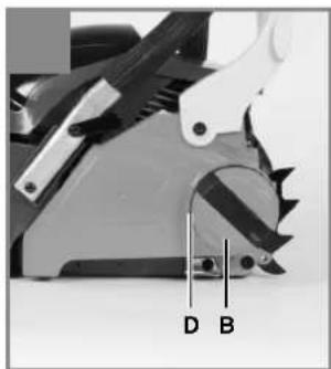
natural_image
Close-up of a mechanical tool with labeled parts D and B (no readable text or symbols beyond labels)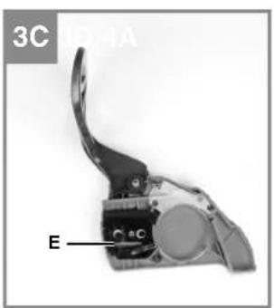
text_image
3C ID-4A E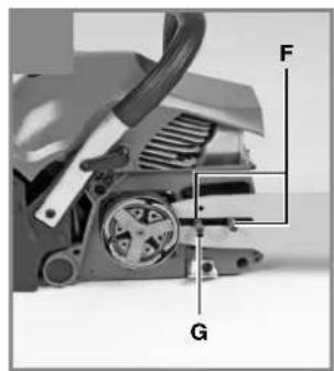
text_image
F G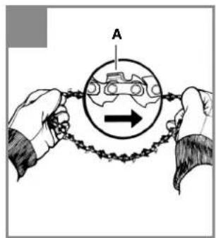
text_image
A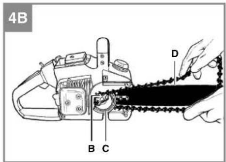
text_image
4B B C D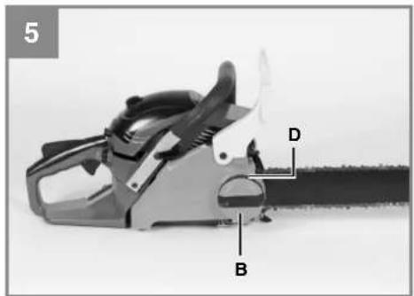
natural_image
Close-up of a chainocopper with labeled parts (B, D) and part number 5 (no text or symbols on the object itself)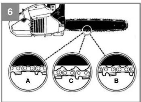
text_image
6 A C B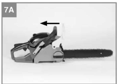
natural_image
Close-up of a chain-linking tool with an arrow indicating motion (no text or symbols visible)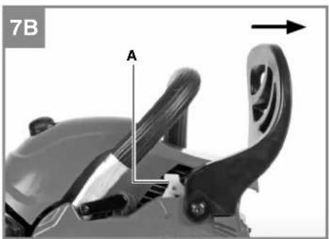
natural_image
Close-up of a mechanical device with labeled component A and directional arrow (no readable text or symbols)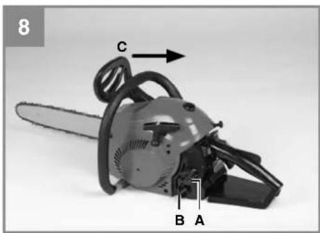
natural_image
Close-up of a chainingsaw with labeled parts (A, B, C) and an arrow indicating direction (no text beyond labels)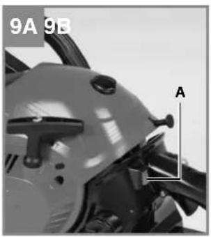
natural_image
Close-up of a motorcycle's head and side panel, labeled '9A 9B' with an arrow pointing to component A (no other text or symbols visible)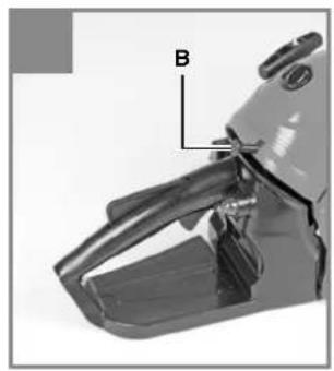
natural_image
Close-up of a mechanical component with labeled part B (no text or symbols beyond label)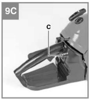
natural_image
Close-up of a mechanical component with labeled parts (C and 9C), no readable text or symbols beyond labels
natural_image
Line drawing of a person sitting on a platform wearing headphones, holding a device (no text or symbols)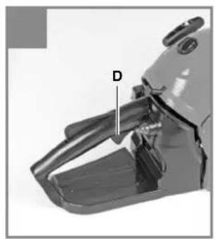
natural_image
Close-up of a mechanical component with labeled part D (no text or symbols beyond label)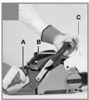
text_image
A B C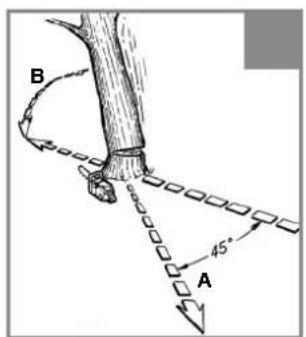
text_image
B 45° A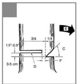
text_image
1.5"-2.0" 3/4 1/4 3-5 cm D C F E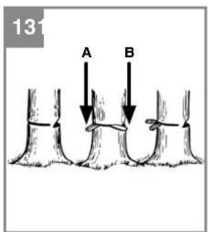
text_image
13 A B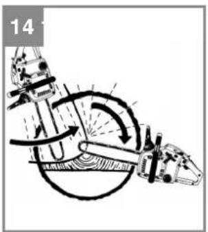
natural_image
Diagram of a mechanical device with rotating components and motion arrows, no visible text or symbols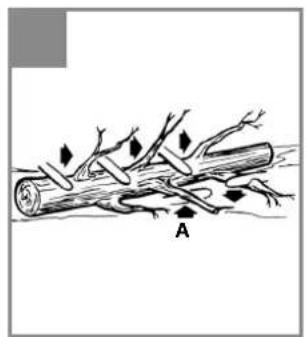
natural_image
Diagram of a tree branch with leaves and roots, labeled 'A' (no text or symbols beyond label)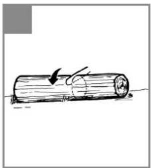
natural_image
Simple line drawing of a wooden log being pulled with a curved arrow (no text or symbols)
natural_image
Illustration of a wooden log being cut with a hammer, showing wood and grass (no text or symbols)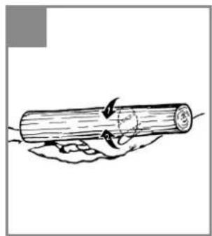
natural_image
Hand holding a cylindrical object with arrows indicating motion or rotation (no text or symbols)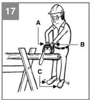
text_image
17 A B C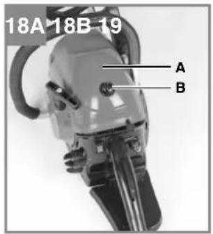
text_image
18A 18B 19 A B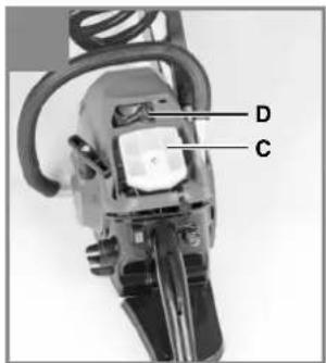
text_image
D C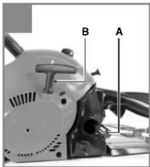
text_image
B A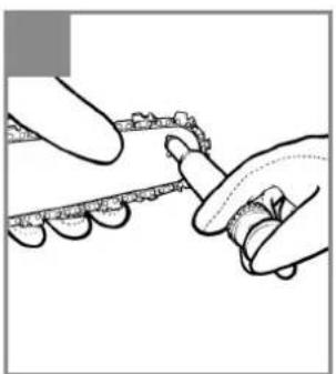
natural_image
Illustration of hands using a tool to apply material or tools (no text or symbols visible)
natural_image
Illustration of a hand holding a black object with a pen tip, no text or symbols present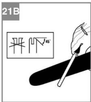
text_image
21B 45°
text_image
22 D 2 85° 30° 60° 0,65mm (0.025")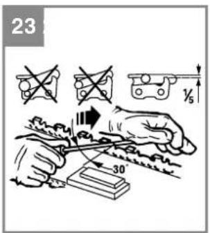
text_image
23 30
natural_image
Diagram of a mechanical device with a tool and clamped parts, showing motion (no text or symbols)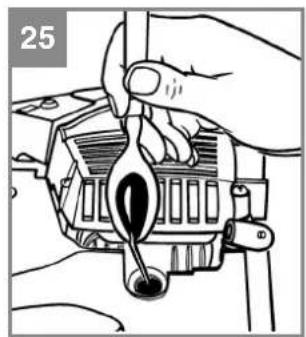
natural_image
Illustration of a hand using a tool to adjust or install a mechanical component (no text or symbols visible)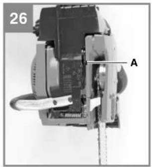
natural_image
Mechanical assembly diagram showing a motor or gear mechanism with labeled component A (no readable text or symbols)D
Inhaltsverzeichnis
natural_image
Simple black-and-white icons representing fuel, water, and a device (no text or symbols)- Safety regulations
- Layout and items supplied
- Proper use
- Technical data
- Before starting the equipment
- Operation
- Cleaning, maintenance, storage and ordering of spare parts
- Disposal and recycling
- Troubleshooting guide
GB
Danger!
When using the equipment, a few safety precautions must be observed to avoid injuries and damage. Please read the complete operating instructions and safety regulations with due care. Keep this manual in a safe place, so that the information is available at all times. If you give the equipment to any other person, hand over these operating instructions and safety regulations as well. We cannot accept any liability for damage or accidents which arise due to a failure to follow these instructions and the safety instructions.
1. Safety regulations
The corresponding safety information can be found in the enclosed booklet.
Danger!
Read all safety regulations and instructions. Any errors made in following the safety regulations and instructions may result in an electric shock, fire and/or serious injury.
Keep all safety regulations and instructions in a safe place for future use.
2. Layout and items supplied
2.1 Layout (Fig. 1)
- Chain bar
- Saw chain
- Sprocket wheel
- Stop claw
- Chain brake lever / front hand guard
- Front handle
- Starter handle
- Spark plug (under the air filter cover)
- Air fi Iter cover
- Stop switch
- Safety lock
- Oil tank cap
- Fan housing
- Fuel tank cap
- Rear handle / bootstrap
- Chain guard
- Choke / (carburetor setting)
- Bar fastening wheel
- Throttle lever
- Chain catch
Safety features (fi g.1)
2 LOW KICKBACK SAW CHAIN helps significantly reduce kickback, or the intensity of kickback, due to specially designed depth gauges and guard links.
5 CHAIN BRAKE LEVER / HAND GUARD protects the operator's left hand in the event it slips off the front handle while saw is running.
5 CHAIN BRAKE is a safety feature designed to reduce the possibility of injury due to kickback by stopping a moving saw chain in milliseconds. It is activated by the CHAIN BRAKE lever.
10 STOP SWITCH immediately stops the engine when tripped. Stop switch must be pushed to ON position to start or restart engine.
11 SAFETY TRIGGER prevents accidental acceleration of the engine. Throttle trigger (19) cannot be squeezed unless the safety latch is depressed.
20 CHAIN CATCHER reduces the danger of injury in the event saw chain breaks or derails during operation. The chain catcher is designed to intercept a whipping chain.
Note: Study your saw and be familiar with its parts.
2.2 Items supplied
Please check that the article is complete as specified in the scope of delivery. If parts are missing, please contact our service center or the sales outlet where you made your purchase at the latest within 5 working days after purchasing the product and upon presentation of a valid bill of purchase. Also, refer to the warranty table in the service information at the end of the operating instructions.
- Open the packaging and take out the equipment with care.
- Remove the packaging material and any packaging and/or transportation braces (if available).
- Check to see if all items are supplied.
- Inspect the equipment and accessories for transport damage.
- If possible, please keep the packaging until the end of the guarantee period.
Danger!
The equipment and packaging material are not toys. Do not let children play with plastic bags, foils or small parts. There is a danger of swallowing or suffocating!
GB
• Original operating instructions
• Safetyinstructions
3. Proper use
The chain is designed exclusively for sawing wood. You may only fell trees if you have received the appropriate training. The manufacturer cannot be held liable for damage caused by improper or incorrect usage.
The equipment is to be used only for its prescribed purpose. Any other use is deemed to be a case of misuse. The user / operator and not the manufacturer will be liable for any damage or injuries of any kind caused as a result of this.
Please note that our equipment has not been designed for use in commercial, trade or industrial applications. Our warranty will be voided if the machine is used in commercial, trade or industrial businesses or for equivalent purposes.
4. Technical data
Engine displacement 41 cm ^3
Maximum engine capacity 1.5 kW
Bar length 33.5 cm
Cutter rail length 14" (35 cm)
Chain pitch .....(3/8"), 9.525 mm
Chain thickness .....(0.05"), 1.27 mm
Idling speed 3300 ± 300 rpm
Maximum speed with
cutting equipment 11000 rpm
Tank capacity 260 ml
Oil tank capacity 210 ml
Anti-vibration function ....Yes
Chain wheel teeth 6 teeth x 9.525 mm
Chain brake Yes
Clutch Yes
Automatic chain lubrication ....Yes
Low-kickback chain Yes
Net weight without chain and chain bar .....4.5 kg
Net weight (dry) 5.4 kg
Fuel consumption (specific) 702 g / kWh
L_pA sound pressure level 99 dB(A)
K_p0^p1 uncertainty 3 dB(A)
L_WA sound power level ..... 114 dB(A)
K_WA uncertainty 1.5 dB(A)
Vibration a_w (front handle) ....max. 6.5 m/s²
K_bv uncertainty 1.5 m/s²
Vibration a_w (rear handle) ....max. 6.0 m/s²
Khv uncertainty 1.5 m/s²
Chain type ......OREGON 91P053X
Bar type ......OREGON 140SDEA041
Chain type (optional) ......KANGXIN 3/8LP-53
Cutter rail type (optional) ....
KANGXIN AP14-53-507P
Spark plug ....L8RTF
5. Before starting the equipment
Danger: Do not start the engine until the saw is fully assembled.
Caution: Wear protective gloves at all times when handling the chain.
5.1 Fit the chain bar
To ensure that the bar and the chain are supplied with oil, USE ONLY THE ORIGINAL BAR. The oil-ling hole (Fig. 2/Item A) must be kept clear of dirt and any build-up of residue.
-
Make sure the Chain brake lever is pulled back into the DISENGAGED position (Fig. 3A)
-
Remove the bar fastening wheel (B). Remove the cover (Fig. 3B).
-
Turn the chain tensioning wheel (D) IN COUNTER-CLOCKWISE DIRECTION until the HINGE (E) (projecting tip) is at the end of its sliding path in the direction of the coupling roller and gear wheel (Fig. 3B/3C).
-
Fit the open end of the chain bar over the bar pins (F). Align the bar such that the HINGE fi ts into the hole (G) in the chain bar (Fig. 3C/3D).
5.2 To install saw chain
-
Spread chain out in a loop with cutting edges (A) pointing CLOCKWISE around loop (Fig. 4A).
-
Slip the chain around the sprocket (B) behind the clutch (C). Make sure the links fit between the sprocket teeth (Fig. 4B).
-
Guide the drive links into the groove (D) and around the end of the bar (Fig. 4B).
NOTE: The saw chain may droop slightly on the lower part of bar. This is normal.
- Pull the chain bar forward until the chain is
GB
closely seated. Make sure that all the drive links are in the groove of the bar.
- Attach the coupling cover (Fig. 5) and turn the bar fastening wheel (B) clockwise to secure it. The chain is not allowed to slip off the guide bar when you do this. Tighten the bar fastening wheel by hand and then follow the instructions for adjusting the chain tension as described in the section ADJUSTING THE CHAIN TENSION.
5.3. Adjusting the chain tension
The correct tension of the saw chain is extremely important and must be checked before starting and during all sawing work. If you take time to adjust the saw chain correctly, you will be able to make better cuts and the life of the chain will be prolonged. Caution: Wear high-strength gloves at all times when handling or adjusting the saw chain.
- Hold the tip of the chain bar upwards and turn the chain tensioning wheel (D) IN CLOCKWISE DIRECTION in order to increase the chain tension (Fig. 5). If you turn the chain tensioning wheel IN COUNTER-CLOCKWISE DI- RECTION, the chain tension will be reduced. Check that the chain is seated around the entire chain bar (Fig. 6).
- After making the adjustment and with the tip of the bar still upwards, tighten the bar fastening wheel (B). The chain is correctly tension when it is closely seated and can be pulled right around by hand.
Note: If the chain is hard to turn around the chain bar or blocked, it is too tightly tensioned. Make the following small adjustments:
A. Undo the bar fastening wheel (B) by 1/2 revolution. Slacken the chain tension by slowly turning the chain tensioning wheel (D) IN COUNTER-CLOCKWISE DIRECTION. Pull the chain back and forth on the bar. Do this until the chain can be moved smoothly but is still closely seated. Increase the tension by turning the chain tensioning wheel IN CLOCKWISE DIRECTION.
B. When the saw chain is correctly tensioned, hold the tip of the bar upwards and tighten the bar fastening wheel (B).
Note: A new saw chain stretches, requiring adjustment after as few as 5 cuts. This is normal with a new chain, and the interval between future adjustments will lengthen quickly.
Note: If the saw chain is TOO LOOSE or TOO TAUT, the drive wheel, chain bar, chain and crank shaft bearing will suffer premature wear. Fig. 6 shows the correct tension A (when cold) and tension B (when warm). Fig. C shows a chain that is too loose.
5.4 Chain break mechanical test
Your chain saw is equipped with a Chain brake that reduces possibility of injury due to kickback. The brake is activated if pressure is applied against brake lever when, as in the event of kickback, operator's hand strikes the lever. When the brake is actuated, chain movement stops abruptly.
Danger: The purpose of the chain brake is to reduce the possibility of injury due to kickback; however, it cannot provide the intended measure of protection if the saw is operated carelessly. Always test the chain brake before using your saw and periodically while on the job.
To test chain brake
- The Chain brake is DISENGAGED (chain can move) when BRAKE LEVER IS PULLED BACK AND LOCKED (Fig. 7A).
- The chain brake is ENGAGED (the chain is locked) when the brake lever is pulled forward and the mechanism (Fig. 7B/Item A) can be seen. It should not be possible to move the chain (Fig. 7B).
Danger: The brake lever should snap into both positions. If strong resistance is felt, or lever does not move into either position, do not use your saw. Take it immediately to a professional Service Center for repair.
5.5 Fuel and lubrication
Fuel
Use regular grade unleaded gasoline mixed with 40:1 custom 2-cycle engine oil for best results.
Mixing fuel
Mix fuel with 2 cycle oil in an approved container. Shake container to ensure thorough mix.
Note: Never use straight gasoline in your unit. This will cause permanent engine damage and void the manufacturer's warranty for that product. Never use a fuel mixture that has been stored for over 90 days.
GB
Note: If 2-cycle lubricant is to be used, it must be a premium grade oil for 2-cycle air cooled engines mixed at a 40:1 ratio. Do not use any 2-cycle oil product with a recommended mixing ratio of 100:1. If insufficient lubrication is the cause of engine damage, it voids the manufacturer's engine warranty for that occurrence.

natural_image
Simple black-and-white icons representing fuel, water, and a container (no text or symbols)Gasoline and Oil Mix 40:1
Oil Only
Recommended fuels
Some conventional gasolines are being blended with oxygenates such as alcohol or an ether compound to meet clean air standards. Your engine is designed to operate satisfactorily on any gasoline intended for automotive use including oxygenated gasolines. It is recommended to use unleaded petrol as fuel.
Lubrication of chain and chain bar
Whenever you refi ll the fuel tank with petrol you must also top up the level of chain oil in the chain oil tank. It is recommended to use standard chain oil.
Engine pre-start checks
Danger: Never start or operate the saw unless the bar and chain are properly installed.
- Fill the fuel tank (A) with correct fuel mixture (Fig. 8).
- Fill the oil tank (B) with chain oil (Fig. 8).
- Be certain the chain brake is disengaged (C) before starting unit (Fig. 8).
Once you have filled the chain and oil tank, tighten the tank cover securely by hand. Do not use any tools to do so.
6. Operation
6.1 Starting the engine
- Set the On/Off switch (A) to "On (I)" to start the machine (Fig. 9A).
- Pull out the choke lever (B) (Fig. 9B) until it locks.
- Push the primer bulb (C) 10 times (Fig. 9C).
- Place saw on a firm, flat surface. Hold saw firmly as shown. Pull starter rapidly 2 times. Beware of moving chain! (Fig.9D)
-
Push in the choke lever (B) as far as it will go (Fig. 9B).
-
Hold saw firmly and pull starter rapidly 4 times. Engine should start (Fig. 9D).
- Let the engine run for 10 seconds to warm up. Press the throttle lever (D) briefly, the engine will go to "idling" speed (Fig. 9E).
If engine failed to start, repeat these instructions.
Note: Always pull the starter cable slowly until you feel the initial resistance before you then pull it quickly to start the engine. Do not allow the starter cable to whip back of its own accord.
6.2 Restarting a warm engine
- Make sure the switch is in the ON position.
- Pull the starter rope rapidly 6 times. The engine should start.
6.3 To stop engine
- Release trigger and allow engine to return to idle speed.
- Move STOP switch down to stop engine.
Note: To stop the engine in an emergency, activate the chain brake and switch the ON/OFF switch to "Stop (0)".
6.4 General cutting instructions
Danger: Felling trees is prohibited without the necessary training!
Felling
- Felling is the term for cutting down a tree. Small trees up to 6-7 inches (15-18cm) in diameter are usually cut in a single cut. Larger trees require notch cuts. Notch cuts determine the direction the tree will fall.
- A retreat path (A) should be planned and cleared as necessary before cuts are started. The retreat path should extend back and dia-
GB
gonally to the rear of the expected line of fall, as illustrated in Fig. 11.
- If felling a tree on sloping ground, the chain saw operator should keep on the uphill side of the terrain, as the tree is likely to roll or slide downhill after it is felled.
- Direction of fall (B) is controlled by the not-ching cut. Before any cuts are made, consider the location of larger branches and natural lean of the tree to determine the way the tree will fall (Fig. 11).
- Do not cut down a tree during high or changing winds or if there is a danger to property. Consult a tree professional. Do not cut down a tree if there is a danger of striking utility wires; notify the utility company before making any cuts.
General guidelines for felling trees (Fig. 12)
Normally felling consists of 2 main cutting operations, notching (C) and making the felling cut (D).
- Start making the upper notch cut (C) on the side of the tree facing the felling direction (E). Be sure you don't make the lower cut too deep into the trunk. The notch (C) should be deep enough to create a hinge (F) of sufficient width and strength. The notch should be wide enough to direct the fall of the tree for as long as possible.
- Never walk in front of a tree that has been notched. Make the felling cut (D) from the other side of the tree and 1.5 - 2.0 inches (3-5 cm) above the edge of the notch (C). Never saw completely through the trunk. Always leave a hinge. The hinge guides the tree. If the trunk is completely cut through, control over the felling direction is lost. Insert a wedge or felling lever in the cut well before the tree becomes unstable and starts to move. This will prevent the guidebar from binding in the felling cut if you have misjudged the falling direction. Make sure no bystanders have entered the range of the falling tree before you push it over.
- Before making the final cut, always recheck the area for bystanders, animals or obstacles.
Felling cut
• Use wooden or plastic wedges (A) to prevent binding the bar or chain (B) in the cut. Wedges also control felling (Fig. 13).
- When diameter of wood being cut is greater than the bar length, make 2 cuts as shown (Fig. 14).
- As the felling cut gets close to the hinge, the tree should begin to fall. When tree begins to fall, remove saw from cut, stop engine, put chain saw down, and leave area along retreat path (Fig. 11).
Limbing
- Limbing a tree is the process of removing the branches from a fallen tree. Do not remove supporting limbs (A) until after the log is bucked (cut) into lengths (Fig. 15). Branches under tension should be cut from the bottom up to avoid binding the chain saw.
- Never cut tree limbs while standing on tree trunk.
Bucking
- Bucking is cutting a fallen log into lengths. Make sure you have a good footing and stand uphill of the log when cutting on sloping ground. If possible, the log should be supported so that the end to be cut off is not resting on the ground. If the log is supported at both ends and you must cut in the middle, make a downward cut halfway through the log and then make the undercut. This will prevent the log from pinching the bar and chain. Be careful that the chain does not cut into the ground when bucking as this causes rapid dulling of the chain. When bucking on a slope, always stand on the uphill side.
- Log supported along entire length: Cut from top (overbuck), being careful to avoid cutting into the ground (Fig. 16A).
-
Log supported on 1 end: First, cut from bottom (underbuck) 1/3 diameter of log to avoid splintering. Second, cut from above (overbuck) to meet first cut and avoid pinching (Fig. 16B).
-
Log supported on both ends: First, over-buck 1/3 diameter of log to avoid splintering. Second, underbuck to meet first cut and avoid pinching (Fig. 16C).
- The best way to hold a log while bucking is to use a sawhorse. When this is not possible, the log should be raised and supported by the limb stumps or by using supporting logs. Be sure the log being cut is securely supported.
Bucking using a sawhorse (Fig. 17)
For personal safety and ease of cutting, the correct position for vertical bucking is essential (Fig. 17).
A. Hold the saw firmly with both hands and keep
GB
the saw to the right of your body while cutting.
B. Keep the left arm as straight as possible.
C. Keep weight on both feet.
Caution: When working with the saw, always make sure that the saw chain and chain bar are sufficiently lubricated.
7. Cleaning, maintenance, storage and ordering of spare parts
Disconnect the spark plug boot before doing any cleaning and maintenance work!
7.1 Cleaning
- Keep all safety devices, air vents and the motor housing free of dirt and dust as far as possible. Wipe the equipment with a clean cloth or blow it with compressed air at low pressure.
- We recommend that you clean the device immediately each time you have finished using it.
- Clean the equipment regularly with a moist cloth and some soft soap. Do not use cleaning agents or solvents; these could attack the plastic parts of the equipment. Ensure that no water can seep into the device.
7.2 Maintenance
Warning: All maintenance work on the chainsaw apart from the work described in this manual may only be carried out by authorized after-sales service personnel.
7.2.1 Chain brake operational test
Test the chain brake periodically to ensure proper function.
Perform a chain brake test prior to initial cutting, following extensive cutting, and definitely following any Chain brake service.
Test chain brake as follows (Fig. 10):
- Place saw on a clear, firm, flat surface.
- Start engine.
- Grasp the rear handle (A) with your right hand.
- With your left hand, hold the front handle (B) [not chain brake lever (C)] fi rmly.
- Squeeze the throttle trigger to 1/3 throttle, then immediately activate the chain brake lever (C).
Warning: Activate the chain brake slowly and deliberately. Keep the chain from touching anything; don't let the saw tip forward.
- Chain should stop abruptly. When it does, immediately release the throttle trigger.
Warning: If chain does not stop, turn engine off and take your unit to the nearest Talon Authorized Service Center for service.
- If chain brake functions properly, turn the engine off and return the chain brake to the DISENGAGED position.
7.2.2 Air fi Iter
Note: Never operate saw without the air filter. Dust and dirt will be drawn into engine and damage it. Keep the air filter clean! The air filter must be cleaned or replaced after every 20 hours of service.
Cleaning the air fi Iter (Fig. 18A/18B)
- Remove the top cover (A) by undoing the cover fastening screw (B) on the cover. You can then remove the cover (Fig. 18A).
- Lift out the air filter (C) (Fig. 18B).
- Clean air filter. Wash filter in clean, warm, soapy water. Rinse in clear, cool water. Air dry completely.
Note: It is advisable to have a supply of spare filters.
- Insert the air filter. Fit the cover for the engine/air filter. Make sure that the cover fits perfectly when you do so. Tighten the fastening screw for the cover.
7.2.3 Fuel fi Iter
Note: Never use the saw without a fuel filter. After 100 hours in operation the fuel fi liter should be cleaned or, in case of damage, replaced. Be sure to empty the fuel tank before changing the fi liter.
- Remove the fuel tank cap.
- Bend a piece of soft wire.
- Reach into fuel tank opening and hook fuel line. Carefully pull the fuel line toward the opening until you can reach it with your fingers.
Note: Do not pull hose completely out of tank.
- Lift fi Iter (A) out of tank (Fig. 19).
GB
- Pull off the filter with a twist and clean it; if the filter is damaged, dispose of it.
- Insert a new filter. Place one end of the filter into the tank opening. Make sure that the fi iter is seated in the lower corner of the tank. If necessary, use a long screwdriver to move the fi iter to its correct position, taking care not to damage in the process.
- Fill tank with fresh fuel / oil mixture. See Section Fuel and Lubrication. Install fuel cap.
7.2.4 Spark plug (Fig. 18B)
Note: To ensure that the saw's engine retains its power, the spark plug must be clean and have the correct electrode gap (0.6 mm). The spark plug must be cleaned or replaced after every 20 hours of service.
Set the On/Off switch to Stop (0)".
- Remove the top cover (A) by undoing the cover fastening screw (B) on the cover. You can then remove the cover (Fig. 18A).
- Disconnect the ignition cable (D) from the spark plug by pulling and twisting it simultaneously (Fig. 18B).
- Remove the spark plug using a spark plug wrench. DO NOT USE ANY OTHER TOOLS.
- Clean the spark plug with a copper wire brush or fit a new one.
7.2.5 Carburetor setting
The carburetor has been set to its perfect adjustment at the factory. If it requires adjusting, take the saw to your nearest authorized after-sales service outlet.
Setting the idling speed:
Note: Set the idling speed when the machine is warm. If the engine stalls when the throttle is not pressed and you have ruled out all the other causes listed in section 9 Troubleshooting, the idling speed must be adjusted. To do this turn the idling speed screw (Fig. 19/Item B) clockwise until the machine runs smoothly at idling speed.
If the idling speed is so fast that the cutting tool turns as well, it has to be reduced by turning the idling speed screw counter-clockwise (Fig. 19/Item B) for as long as is required for the cutting tool to stop turning as well.
7.2.6 Chain bar maintenance
Regular lubrication of the chain bar (guide rail for the chain and teeth) is essential. The chain bar needs the maintenance described in the following section in order for the saw to work at an optimum level of performance.
Note: The sprocket tip on your new saw has been pre-lubricated at the factory. Failure to lubricate the guide bar sprocket tip as explained below will result in poor performance and seizure, voiding the manufacturer's warranty.
Tools for lubrication
The Lube Gun (optional) is recommended for applying grease to the guide bar sprocket tip. The Lube Gun is equipped with a needle nose tip which is necessary for the efficient application of grease to the sprocket tip.
To lubricate sprocket tip
Lubrication of the sprocket tip is recommended after 10 hours of use or once a week, which ever occurs first. Always thoroughly clean guide bar sprocket tip before lubrication.
Note: The saw chain does not have to be removed in order to lubricate the teeth of the chain bar. Lubrication is possible during work, with the engine switched off.
Caution: Wear heavy duty work gloves when handling the bar and chain.
- Set the On/Off switch to Stop (0)".
- Clean the guide bar sprocket tip.
- Using the Lube Gun (optional), insert needle nose into the lubrication hole and inject grease until it appears at outside edge of sprocket tip (Fig .20).
- Rotate saw chain by hand. Repeat lubrication procedure until the entire sprocket tip has been greased.
Most guide bar problems can be prevented merely by keeping the chain saw well maintained. Insufficient guide bar lubrication and operating the saw with chain that is TOO TIGHT will contribute to rapid bar wear.
To help minimize bar wear, the following guide bar maintenance procedures are recommended.
Caution: Always wear protective gloves during maintenance operations. Do not carry out maintenance when the engine is hot.
Turning the chain bar
The bar should be reversed every 8 working hours to ensure uniform wear.
Keep the bar groove and lubrication hole clean using the bar groove cleaner supplied optional. (Fig. 21A)
Check the bar rails frequently for wear and, if ne-
GB
cessary, remove the burs and square-up the rails using the flat file. (Fig. 21B)
Caution: Never fit a new chain to a worn chain bar.
Oil passages
Oil passages on the bar should be cleaned to ensure proper lubrication of the bar and chain during operation.
Note: The condition of the oil passages can be easily checked. If the passages are clear, the chain will automatically give off a spray of oil within seconds of starting the saw. Your saw is equipped with an automatic oiler system.
Automatic chain lubrication.
The chain saw is equipped with an automatic oil lubrication system with a toothed wheel drive. It automatically supplies the bar and the chain with the right quantity of oil. The moment the engine is accelerated, the oil also starts to flow through the bar plate more quickly as well.
The chain lubrication system has been set to its perfect adjustment at the factory. If it requires adjusting, take the saw to your nearest authorized after-sales service outlet.
A setting screw for adjusting the chain lubrication (Fig. 26/ Item A) is located on the underside of the chain saw. Turning the screw counter-clockwise increases the chain lubrication, turning it clockwise decreases the chain lubrication.
To check the chain lubrication, hold the chain saw, with the chain, over a piece of paper and run it at full speed for a few seconds. You will be able to judge the set amount of oil from the paper.
7.2.7 Chain maintenance
Chain sharpening
Chain sharpening requires special tools to ensure that cutters are sharpened at the correct angle and depth. For the inexperienced chain saw user, we recommend that the saw chain be professionally sharpened by the nearest professional Service Center. If you feel comfortable sharpening your own saw chain, special tools are available from the professional Service Center.
Chain sharpening (Fig. 23)
Sharpen the chain using protective gloves and a round file of 3 / 16'' (4.8mm).
Always sharpen the cutters only with outward strokes (Fig. 23) observing the values given in Fig. 22.
After sharpening, the cutting links must all have the same width and length.
Note: A sharp chain produces well-defined chips. When your chain starts to produce sawdust, it is time to sharpen.
After the blades have been sharpened 3-4 times, check the height of the depth limiter and if necessary lower it with a flat file and then round off the front corner (Fig. 24).
Chain tension
Check the chain tension frequently and adjust as often as necessary to keep the chain snug on the bar, but loose enough to be pulled around by hand. (see also point 5.3)
Breaking in a new saw chain
A new chain and bar will need chain readjustment after as few as 5 cuts. This is normal during the break-in period, and the interval between future adjustments will begin to lengthen quickly.
Note: Never have more than 3 links removed from a loop of chain. This could cause damage to the sprocket.
Chain lubrication
Always make sure the automatic oiler system is working properly. Keep the oil tank filled with Chain, Bar and Sprocket Oil.
Adequate lubrication of the bar and chain during cutting operations is essential to minimize friction with the guide bar.
Never starve the bar and chain of lubricating oil. Running the saw dry or with too little oil will decrease cutting efficiency, shorten saw chain life, cause rapid dulling of chain, and lead to excessive wear of bar from overheating. Too little oil is evidenced by smoke or bar discoloration.
GB
7.3 Storage
Note: Never put a chain saw into storage for longer than 30 days without carrying out the following steps.
Storing a chain saw
Storing a chain saw for longer than 30 days requires storage maintenance. Unless the storage instructions are followed, fuel remaining in the carburetor will evaporate, leaving gum-like deposits. This could lead to difficult starting and result in costly repairs.
- Remove the fuel tank cap slowly to release any pressure in tank. Carefully drain the fuel tank.
- Start the engine and let it run until the unit stops to remove fuel from carburetor.
- Allow the engine to cool (approx. 5 minutes).
- Remove the spark plug (7.2.4).
- Pour 1 teaspoon of clean 2-cycle oil into the combustion chamber. Pull starter rope slowly several times to coat internal components. Replace spark plug (Fig. 25).
Note: Store the unit in a dry place and away from possible sources of ignition such as a furnace, gas hot water heater, gas dryer, etc.
Puttig the saw back into operation
- Remove spark plug (see also point 7.2.4).
- Pull starter rope briskly to clear excess oil from combustion chamber.
- Clean the spark plug and check that the electrode gap is correct.
- Prepare unit for operation.
- Fill fuel tank with proper fuel / oil mixture. See Fuel and Lubrication Section.
7.4 Ordering replacement parts:
Please quote the following data when ordering replacement parts:
• Type of machine
• Article number of the machine
• Identification number of the machine
• Replacement part number of the part required
For our latest prices and information please go to www.isc-gmbh.info
8. Disposal and recycling
The equipment is supplied in packaging to prevent it from being damaged in transit. The raw materials in this packaging can be reused or recycled. The equipment and its accessories are made of various types of material, such as metal and plastic. Never place defective equipment in your household refuse. The equipment should be taken to a suitable collection center for proper disposal. If you do not know the whereabouts of such a collection point, you should ask in your local council offices.
9. Troubleshooting guide
| Problem Probable cause Corrective Action | ||
| Unit won't start or starts but will not run. | -Incorrect starting procedures.- Incorrect carburetor mixture adjustment setting.- Fouled spark plug.- Fuel fi liter plugged. | - Follow instructions in the User Manual.- Have carburetor adjusted by an Authorized Service Center.- Clean / gap or replace plug.- Replace fuel fi liter. |
| Unit starts, but engine has low power. | - Incorrect lever position on choke.-Dirtyairfi liter.- Incorrect carburetor mixture adjustment setting. | - Move to RUN position.- Remove, clean and reinstall fi liter.- Have carburetor adjusted by an Authorized Service Center. |
| Engine hesitates. - | Incorrect carburetor mixture adjustment setting. | - Have carburetor adjusted by an Authorized Service Center. |
| No power under load. | - Incorrectly gapped spark plug. - Clean / gap or replace plug. | |
| Runs erratically. | - Incorrect carburetor mixture adjustment setting. | - Have carburetor adjusted by an Authorized Service Center. |
| Smokesexcessively. | - Incorrect fuel mixture. | - Use properly mixed fuel (40:1 mixture). |
| Poorperformance when operated | -Bluntchain- Loose chain | - Sharpen or replace the chain- Tension the chain |
| Engine dies | - Empty petrol tank- Fuel fi liter in the wrong position in the tank | - Fill up the petrol tank- Completely fi ll the petrol tank or or re-position the fuel fi liter in the petrol tank |
| Insufficient chain lubrication (the cutter rail and chain get hot) | - Empty oil tank for the chain- Oil lubrication openings moved | - Top up the oil tank for the chain- Clean the oil lubrication hole in the cutter bar (Fig. 2/Item A)Clean the groove in the cutter bar |
The reprinting or reproduction by any other means, in whole or in part, of documentation and papers accompanying products is permitted only with the express consent of the iSC GmbH.
Subject to technical changes
GB
Service information
We have competent service partners in all countries named on the guarantee certificate whose contact details can also be found on the guarantee certificate. These partners will help you with all service requests such as repairs, spare and wearing part orders or the purchase of consumables.
Please note that the following parts of this product are subject to normal or natural wear and that the following parts are therefore also required for use as consumables.
| Category Example | |
| Wear parts* | Cutter bar, spark plug, air filter, petrol filter |
| Consumables* Saw chain | |
| Missing parts |
* Not necessarily included in the scope of delivery!
In the effect of defects or faults, please register the problem on the internet at www.isc-gmbh.info. Please ensure that you provide a precise description of the problem and answer the following questions in all cases:
• Did the equipment work at all or was it defective from the beginning?
• Did you notice anything (symptom or defect) prior to the failure?
• What malfunction does the equipment have in your opinion (main symptom)?
Describe this malfunction.
GB
Warranty certifi cate
Dear Customer,
All of our products undergo strict quality checks to ensure that they reach you in perfect condition. In the unlikely event that your device develops a fault, please contact our service department at the address shown on this guarantee card. You can also contact us by telephone using the service number shown. Please note the following terms under which guarantee claims can be made:
- These warranty terms regulate additional warranty services, which the manufacturer mentioned below promises to buyers of its new products in addition to their statutory rights of guarantee. Your statutory guarantee claims are not affected by this guarantee. Our guarantee is free of charge to you.
- The warranty services cover only defects due to material or manufacturing faults on a product which you have bought from the manufacturer mentioned below and are limited to either the rectification of said defects on the product or the replacement of the product, whichever we prefer. Please note that our devices are not designed for use in commercial, trade or professional applications. A guarantee contract will not be created if the device has been used by commercial, trade or industrial business or has been exposed to similar stresses during the guarantee period.
-
The following are not covered by our guarantee:
-
Damage to the device caused by a failure to follow the assembly instructions or due to incorrect installation, a failure to follow the operating instructions (for example connecting it to an incorrect mains voltage or current type) or a failure to follow the maintenance and safety instructions or by exposing the device to abnormal environmental conditions or by lack of care and maintenance.
- Damage to the device caused by abuse or incorrect use (for example overloading the device or the use or unapproved tools or accessories), ingress of foreign bodies into the device (such as sand, stones or dust, transport damage), the use of force or damage caused by external forces (for example by dropping it).
-
Damage to the device or parts of the device caused by normal or natural wear or tear or by normal use of the device.
-
The guarantee is valid for a period of 24 months starting from the purchase date of the device. Guarantee claims should be submitted before the end of the guarantee period within two weeks of the defect being noticed. No guarantee claims will be accepted after the end of the guarantee period. The original guarantee period remains applicable to the device even if repairs are carried out or parts are replaced. In such cases, the work performed or parts fitted will not result in an extension of the guarantee period, and no new guarantee will become active for the work performed or parts fitted. This also applies if an on-site service is used.
-
Please report the defective device on the following internet address to register your guarantee claim: www.isc-gmbh.info. If the defect is covered by our guarantee, then the item in question will either be repaired immediately and returned to you or we will send you a new replacement device.
Of course, we are also happy offer a chargeable repair service for any defects which are not covered by the scope of this guarantee or for units which are no longer covered. To take advantage of this service, please send the device to our service address.
Also refer to the restrictions of this warranty concerning wear parts, consumables and missing parts as set out in the service information in these operating instructions.
F
Sommaire
Fonction anti-vibration.....oui
natural_image
Simple black-and-white icons representing fuel, water, and a droplet (no text or symbols)Mélange Essence Huile 40:1
Huile Seule
Carburants recommandes
natural_image
Simple black-and-white icons representing fuel, water, and a container (no text or symbols)Kædedeling .....(3/8"), 9,525 mm
natural_image
Simple line icons representing fuel, water, and a container (no text or symbols)Benzin- og olieblanding 40:1 Kun olie
Anbefalet brændstof
natural_image
Simple black-and-white icons representing fuel, water, and a vehicle (no text or symbols)natural_image
Simple black-and-white icons representing fuel, water, and a device (no text or symbols)Mješavina benzina i ulja 40:1 Samo ulje
PREPORUČENA GORIVA
Podela lanca .....(3/8"), 9,525 mm
Debljina lanca (0,05"), 1,27 mm
Broj obrtaja praznog hoda ....3300 ± 300 min ^-1
Maksimalan broj obrtaja
s garniturom za rezanje ....11000 min ^-1
Sadržaj tanka ....260 ml
natural_image
Simple line icons representing fuel, water, and a container (no text or symbols)Smeša benzina i ulja 40:1 Samo ulje
Preporučena goriva
Neki uobičajeni benzini pomešani su sa primesama, kao što su spojevi alkohola ili etera, kako bi odgovarali normama za čiste ispušne gasove. Motor radi na zadovoljavajući način sa svim vrstama benzina sa svrhom sopstvenog pogona, takođe i s benzinima obogaćenima kiseonikom. Najbolje je da koristite bezolovni, normalan benzin.
Podmazivanje lanca i klizne vodilice uljem Svaki put kad punite tank za gorivo benzinom, morate takođe da sipate ulje za podmazivanje lanca u njegov tank. Pritom preporučamo da koristite standardno ulje za lance.
Kontrole pre pokretanja motora
natural_image
Simple black-and-white icons representing fuel, water, and a bag (no text or symbols)natural_image
Simple black-and-white icons representing fuel, gas, and water droplets (no text or symbols)natural_image
Three black-and-white icons: a fuel pump, a funnel with droplets, and a bag with droplets (no text or symbols)natural_image
Simple black-and-white icons representing fuel, water, and a droplet (no text or symbols)natural_image
Simple black-and-white icons representing fuel, water, and a bag (no text or symbols)Mistura gasolina/óleo 40:1
Apenas óleo
Negotovost K_PA 3 dB (A)
natural_image
Simple line icons representing fuel, water, and a container (no text or symbols)natural_image
Simple black-and-white icons representing fuel, water, and a droplet (no text or symbols)X 2000/14/EC\_2005/88/EC
x Annex V
Annex VI
Noise: measured L_wA = 109.6 dB (A); guaranteed L_wA = 114 dB (A)
P = 1,5 KW; L/∅ = cm
Notified Body:
X 2004/26/EC
Emission No.: e11*97/68SA*2012/46*2698*01
Standard references: EN ISO 11681-1; EN ISO 14982
Subject to change without notice
Archive-File/Record: NAPR012218
Documents registrar: Markus Jehl
Wiesenweg 22, D-94405 Landau/Isar
EH 07/2015 (01)