PKS 55 - Circular saw BOSCH - Free user manual and instructions
Find the device manual for free PKS 55 BOSCH in PDF.
| Product type | Circular saw portable |
| Brand | Bosch |
| Model | PKS 55 |
| Rated power input | 1200 W |
| No-load speed | 5600 rpm |
| Max. cutting depth (0°) | 55 mm |
| Max. cutting depth (45°) | 38 mm |
| Max. blade diameter | 160 mm |
| Min. blade diameter | 150 mm |
| Max. blade thickness | 1.8 mm |
| Blade bore | 20 mm |
| Base plate dimensions | 288 x 153 mm |
| Weight (according to EPTA 01/2003) | 3.9 kg |
| Protection class | II (double insulation) |
| Spindle lock | Yes |
| Pendulum guard | Yes |
| Parallel guide | Yes, adjustable |
| Cutting depth adjustment | By clamping lever |
| Bevel angle adjustment | From 0° to 45°, by wing screw |
| Chip ejection | Yes, adaptable for external extraction or box (optional) |
| Sound pressure level | 101 dB(A) |
| Sound power level | 112 dB(A) |
| Vibration emission value (ah) | 4.0 m/s² |
| Maintenance and cleaning | Clean ventilation slots, guard and blade regularly; use compressed air |
| Safety | Double safety switch (unlock + on/off), pendulum guard, detailed safety instructions in the manual |
| Spare parts and repairability | Repair exclusively by Bosch authorized service; use original spare parts |
| General information | Manual available in several languages; CE certification; use: wood, non-ferrous metals (except ferrous) |
Frequently Asked Questions - PKS 55 BOSCH
User questions about PKS 55 BOSCH
0 question about this device. Answer the ones you know or ask your own.
Ask a new question about this device
Download the instructions for your Circular saw in PDF format for free! Find your manual PKS 55 - BOSCH and take your electronic device back in hand. On this page are published all the documents necessary for the use of your device. PKS 55 by BOSCH.
USER MANUAL PKS 55 BOSCH
natural_image
Technical illustration of a Bosch cutting cutter with visible components and mounting base (no text or symbols)Robert Bosch GmbH
Power Tools Division
70745 Leinfelden-Echterdingen
Germany
www.bosch-pt.com
1 609 929 S13 (2010.03) O / 153 WEU

1 609 929 S13
PKS
55 | 55 A | 66 A | 66 AF

BOSCH
natural_image
Mechanical assembly diagram showing a Bosch motor with gear and exhaust plume (no text or symbols)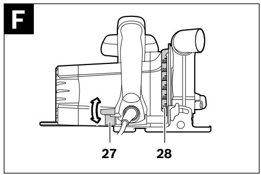
1 609 929 S13 | (19.3.10)
Bosch Power Tools
natural_image
Mechanical assembly diagram of a Bosch cutting tool on a workbench, showing hands operating the cutter (no text or symbols present)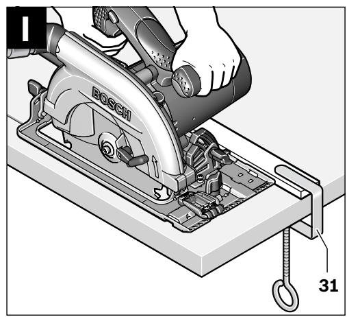
natural_image
Mechanical assembly diagram showing a person using a Bosch circular cutter on a workbench, with part number 31 indicated (no text or symbols beyond labels)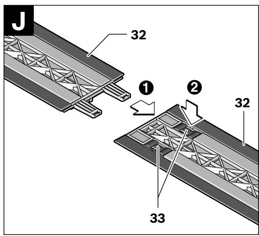
natural_image
Mechanical assembly diagram showing a hand operating a workpiece with labeled component '31' (no text or symbols beyond label)Bosch Power Tools
1 609 929 S13 | (19.3.10)


6 | Deutsch
Sicherheitshinweise
Dr. Egbert Schneider Dr. Eckerhard Strötgen Senior Vice President Head of Product Engineering Certification
ppa. dawala i.v. nuoyen
Robert Bosch GmbH, Power Tools Division D-70745 Leinfelden-Echterdingen 08.03.2010
Montage

General Power Tool Safety Warnings
WARNING Read all safety warnings and all instructions. Failure to follow
the warnings and instructions may result in electric shock, fire and/or serious injury.
Save all warnings and instructions for future reference.
The term “power tool” in the warnings refers to your mains-operated (corded) power tool or battery-operated (cordless) power tool.
1) Work area safety
a) Keep work area clean and well lit. Cluttered or dark areas invite accidents.
b) Do not operate power tools in explosive atmospheres, such as in the presence of flammable liquids, gases or dust. Power tools create sparks which may ignite the dust or fumes.
c) Keep children and bystanders away while operating a power tool. Distractions can cause you to lose control.
2) Electrical safety
a) Power tool plugs must match the outlet. Never modify the plug in any way. Do not use any adapter plugs with earthed (grounded) power tools. Unmodified plugs and matching outlets will reduce risk of electric shock.
b) Avoid body contact with earthed or grounded surfaces, such as pipes, radiators, ranges and refrigerators. There is an increased risk of electric shock if your body is earthed or grounded.
c) Do not expose power tools to rain or wet conditions. Water entering a power tool will increase the risk of electric shock.
d) Do not abuse the cord. Never use the cord for carrying, pulling or unplugging the power tool. Keep cord away from heat, oil, sharp edges and moving parts. Damaged or entangled cords increase the risk of electric shock.
e) When operating a power tool outdoors, use an extension cord suitable for outdoor use. Use of a cord suitable for outdoor use reduces the risk of electric shock.
f) If operating a power tool in a damp location is unavoidable, use a residual current device (RCD) protected supply. Use of an RCD reduces the risk of electric shock.
3) Personal safety
a) Stay alert, watch what you are doing and use common sense when operating a power tool. Do not use a power tool while you are tired or under the influence of drugs, alcohol or medication. A moment of inattention while operating power tools may result in serious personal injury.
b) Use personal protective equipment. Always wear eye protection. Protective equipment such as dust mask, non-skid safety shoes, hard hat, or hearing protection used for appropriate conditions will reduce personal injuries.
c) Prevent unintentional starting. Ensure the switch is in the off-position before connecting to power source and/or battery pack, picking up or carrying the tool. Carrying power tools with your finger on the switch or energising power tools that have the switch on invites accidents.
d) Remove any adjusting key or wrench before turning the power tool on. A wrench or a key left attached to a rotating part of the power tool may result in personal injury.
e) Do not overreach. Keep proper footing and balance at all times. This enables better control of the power tool in unexpected situations.
f) Dress properly. Do not wear loose clothing or jewellery. Keep your hair, clothing and gloves away from moving parts.
Loose clothes, jewellery or long hair can be caught in moving parts.


g) If devices are provided for the connection of dust extraction and collection facilities, ensure these are connected and properly used. Use of dust collection can reduce dust-related hazards.
4) Power tool use and care
a) Do not force the power tool. Use the correct power tool for your application. The correct power tool will do the job better and safer at the rate for which it was designed.
b) Do not use the power tool if the switch does not turn it on and off. Any power tool that cannot be controlled with the switch is dangerous and must be repaired.
c) Disconnect the plug from the power source and/or the battery pack from the power tool before making any adjustments, changing accessories, or storing power tools. Such preventive safety measures reduce the risk of starting the power tool accidentally.
d) Store idle power tools out of the reach of children and do not allow persons unfamiliar with the power tool or these instructions to operate the power tool. Power tools are dangerous in the hands of untrained users.
e) Maintain power tools. Check for misalignment or binding of moving parts, breakage of parts and any other condition that may affect the power tool's operation. If damaged, have the power tool repaired before use. Many accidents are caused by poorly maintained power tools.
f) Keep cutting tools sharp and clean. Properly maintained cutting tools with sharp cutting edges are less likely to bind and are easier to control.
g) Use the power tool, accessories and tool bits etc. in accordance with these instructions, taking into account the working conditions and the work to be performed. Use of the power tool for operations different from those intended could result in a hazardous situation.
5) Service
a) Have your power tool serviced by a qualified repair person using only identical replacement parts. This will ensure that the safety of the power tool is maintained.
Safety Warnings for Circular Saws
▶ DANGER: Keep hands away from cutting area and the blade. Keep your second hand on auxiliary handle, or motor housing. If both hands are holding the saw, they cannot be cut by the blade.
▶ Do not reach underneath the workpiece.
The guard cannot protect you from the blade below the workpiece.
▶ Adjust the cutting depth to the thickness of the workpiece. Less than a full tooth of the blade teeth should be visible below the workpiece.
▶ Never hold the workpiece being cut in your hands or across your leg. Secure the workpiece to a stable platform. It is important to support the work properly to minimize body exposure, blade binding, or loss of control.
Hold the power tool only by the insulated gripping surfaces when performing an operation where the cutting tool may contact hidden wiring or its own cord. Contact with a “live” wire will also make exposed metal parts of the power tool “live” and shock the operator.
▶ When ripping always use a rip fence or straight edge guide. This improves the accuracy of cut and reduces the chance of blade binding.
▶ Always use blades with correct size and shape (diamond versus round) of arbour holes. Blades that do not match the mounting hardware of the saw will run eccentrically, causing loss of control.
▶ Never use damaged or incorrect blade washers or bolt. The blade washers and bolt were specially designed for your saw, for optimum performance and safety of operation.


20 | English
▶ Causes and operator prevention of kick-back:
- Kickback is a sudden reaction to a pinched, bound or misaligned saw blade, causing an uncontrolled saw to lift up and out of the workpiece toward the operator. - When the blade is pinched or bound tightly by the kerf closing down, the blade stalls and the motor reaction drives the unit rapidly back toward the operator.
- If the blade becomes twisted or misaligned in the cut, the teeth at the back edge of the blade can dig into the top surface of the wood causing the blade to climb out of the kerf and jump back toward the operator. Kickback is the result of saw misuse and/or incorrect operating procedures or conditions and can be avoided by taking proper precautions as given below.
- Maintain a firm grip with both hands on the saw and position your arms to resist kickback forces. Position your body to either side of the blade, but not in line with the blade. Kickback could cause the saw to jump backwards, but kickback forces can be controlled by the operator, if proper precautions are taken.
When blade is binding, or when interrupting a cut for any reason, release the trigger and hold the saw motionless in the material until the blade comes to a complete stop. Never attempt to remove the saw from the work or pull the saw backward while the blade is in motion or kickback may occur. Investigate and take corrective actions to eliminate the cause of blade binding.
When restarting a saw in the workpiece, centre the saw blade in the kerf and check that saw teeth are not engaged into the material. If saw blade is binding, it may walk up or kickback from the workpiece as the saw is restarted.
▶ Support large panels to minimise the risk of blade pinching and kickback. Large panels tend to sag under their own weight. Supports must be placed under the panel on both sides, near the line of cut and near the edge of the panel.
▶ Do not use dull or damaged blades. Unsharpened or improperly set blades produce narrow kerf causing excessive friction, blade binding and kickback.
▶ Blade depth and bevel adjusting locking levers must be tight and secure before making cut. If blade adjustment shifts while cutting, it may cause binding and kickback.
▶ Use extra caution when making a “plunge cut” into existing walls or other blind areas. The protruding blade may cut objects that can cause kickback.
▶ Check lower guard for proper closing before each use. Do not operate the saw if lower guard does not move freely and close instantly. Never clamp or tie the lower guard into the open position. If saw is accidentally dropped, lower guard may be bent. Raise the lower guard with the retracting handle and make sure it moves freely and does not touch the blade or any other part, in all angles and depths of cut.
▶ Check the operation of the lower guard spring. If the guard and the spring are not operating properly, they must be serviced before use. Lower guard may operate sluggishly due to damaged parts, gummy deposits, or a build-up of debris.
▶ Lower guard should be retracted manually only for special cuts such as “plunge cuts” and “compound cuts”. Raise lower guard by retracting handle and as soon as blade enters the material, the lower guard must be released. For all other sawing, the lower guard should operate automatically.
▶ Always observe that the lower guard is covering the blade before placing saw down on bench or floor. An unprotected, coasting blade will cause the saw to walk backwards, cutting whatever is in its path. Be aware of the time it takes for the blade to stop after switch is released.
▶ Do not reach into the saw dust ejector with your hands. They could be injured by rotating parts.
▶ Do not work overhead with the saw. In this manner you do not have sufficient control over the power tool.

▶ Use suitable detectors to determine if utility lines are hidden in the work area or call the local utility company for assistance.
Contact with electric lines can lead to fire and electric shock. Damaging a gas line can lead to explosion. Penetrating a water line causes property damage or may cause an electric shock.
▶ Do not operate the power tool stationary. It is not designed for operation with a saw table.
▶ Do not use high speed steel (HSS) saw blades. Such saw blades can easily break.
▶ Do not saw ferrous metals. Red hot chips can ignite the dust extraction.
▶ When working with the machine, always hold it firmly with both hands and provide for a secure stance. The power tool is guided more secure with both hands.
- Secure the workpiece. A workpiece clamped with clamping devices or in a vice is held more secure than by hand.
▶ Always wait until the machine has come to a complete stop before placing it down. The tool insert can jam and lead to loss of control over the power tool.
▶ Never use the machine with a damaged cable. Do not touch the damaged cable and pull the mains plug when the cable is damaged while working. Damaged cables increase the risk of an electric shock.
Products sold in GB only: Your product is fitted with an BS 1363/A approved electric plug with internal fuse (ASTA approved to BS 1362).
If the plug is not suitable for your socket outlets, it should be cut off and an appropriate plug fitted in its place by an authorised customer service agent. The replacement plug should have the same fuse rating as the original plug.
The severed plug must be disposed of to avoid a possible shock hazard and should never be inserted into a mains socket elsewhere.
Products sold in AUS and NZ only: Use a residual current device (RCD) with a rated residual current of 30 mA or less.
Functional Description

Read all safety warnings and all instructions. Failure to follow the warnings and instructions may result in electric shock, fire and/or serious injury.
Intended Use
The machine is intended for lengthways and crossways cutting of wood with straight cutting lines as well as mitre cuts in wood while resting firmly on the workpiece. With suitable saw blades, thin-walled non-ferrous metals, e. g., profiles, can also be sawed.
Working ferrous metals is not permitted.
Product Features
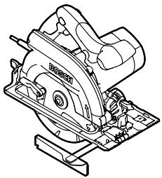
The numbering of the product features refers to the illustration of the machine on the graphics page.
1 Lock-off button for On/Off switch
2 On/Off switch
3 Auxiliary handle (insulated gripping surface)
4 Spindle lock button
5 Scale for mitre angle
6 Allen key
7 Wing bolt for bevel-angle preselection
8 Wing bolt for parallel guide
9 "CutControl" – Viewing window for cutting line (PKS 55 A/PKS 66 A/PKS 66 AF)
10 Parallel guide
11 Retracting blade guard
12 Base plate
13 Lever for retracting blade guard
14 Wing bolt for bevel-angle preselection
15 Blade guard
16 Sawdust ejector
17 Handle (insulated gripping surface)
18 Clamping bolt with washer
19 Clamping flange
20 Saw blade*
21 Mounting flange
22 Saw spindle


22 | English
23 Vacuum hose*
24 Deflection tube for chips
25 Dust/chip box*
26 Slider of dust/chip box
27 Clamping lever for cutting-depth preselection
28 Cutting-depth scale
29 Cutting mark, 45°
30 Cutting mark, 0^
31 Material clamp*
32 Guide rail*
33 Button for guide-rail lock
*Accessories shown or described are not part of the standard delivery scope of the product. A complete overview of accessories can be found in our accessories program.
Technical Data
| Circular Saw | PKS 55 | PKS 55 A | PKS 66 A PKS 66 AF* | |
| Article number | 3 603 E00 0.. | 3 603 E01 0.. | 3 603 E02 0.. | |
| Rated power input | W | 1200 | 1200 | 1600 |
| No-load speed | min^-1 | 5600 | 5600 | 5000 |
| Cutting depth, max. | ||||
| - for 0° bevel angle | mm | 55 | 55 | 66 |
| - for 45° bevel angle | mm | 38 | 38 | 48 |
| Spindle lock | ● | ● | ● | |
| CutControl | - | ● | ● | |
| Dust/chip box | - | ● | ● | |
| Base plate dimensions | mm | 288 x 153 | 288 x 153 | 327 x 160 |
| Saw blade diameter, max. | mm | 160 | 160 | 190 |
| Saw blade diameter, min. | mm | 150 | 150 | 184 |
| Blade thickness, max. | mm | 1.8 | 1.8 | 1.8 |
| Mounting bore | mm | 20 | 20 | 30 |
| Weight according to EPTA-Procedure 01/2003 | kg | 3.9 | 3.9 | 5.4 |
| Protection class | ☐ / II | ☐ / II | ☐ / II | |
The values given are valid for nominal voltages [U] of 230/240 V. For lower voltage and models for specific countries, these values can vary.
Please observe the article number on the type plate of your machine. The trade names of the individual machines may vary.
Only for power tools without reduced starting current: Starting cycles generate brief voltage drops. Interference with other equipment/machines may occur in case of unfavourable mains system conditions. Malfunctions are not to be expected for system impedances below 0.36 ohm.
* PKS 66 AF with guide rail


Noise/Vibration Information
Measured sound values determined according to EN 60745.
Typically the A-weighted noise levels of the product are: Sound pressure level 101 dB(A); Sound power level 112 dB(A). Uncertainty K=3 dB.
Wear hearing protection!
Vibration total values (triax vector sum) determined according to EN 60745:
Vibration emission value a_h=4.0 m/s^2 , Uncertainty K=1.5 m/s^2 .
The vibration emission level given in this information sheet has been measured in accordance with a standardised test given in EN 60745 and may be used to compare one tool with another. It may be used for a preliminary assessment of exposure.
The declared vibration emission level represents the main applications of the tool. However if the tool is used for different applications, with different accessories or poorly maintained, the vibration emission may differ. This may significantly increase the exposure level over the total working period.
An estimation of the level of exposure to vibration should also take into account the times when the tool is switched off or when it is running but not actually doing the job. This may significantly reduce the exposure level over the total working period.
Identify additional safety measures to protect the operator from the effects of vibration such as: maintain the tool and the accessories, keep the hands warm, organisation of work patterns.
Declaration of Conformity CE
We declare under our sole responsibility that the product described under “Technical Data” is in conformity with the following standards or standardization documents: EN 60745 according to the provisions of the directives 2004/108/EC, 2006/42/EC.
Technical file at:
Robert Bosch GmbH, PT/ESC,
D-70745 Leinfelden-Echterdingen
Dr. Egbert Schneider Senior Vice President Engineering
Dr. Eckerhard Strötgen Head of Product Certification

Robert Bosch GmbH, Power Tools Division
D-70745 Leinfelden-Echterdingen
08.03.2010
Assembly
Mounting/Replacing the Saw Blade
▶ Before any work on the machine itself, pull the mains plug.
- When mounting the saw blade, wear protective gloves. Danger of injury when touching the saw blade.
▶ Only use saw blades that correspond with the characteristic data given in the operating instructions.
▶ Do not under any circumstances use grinding discs as the cutting tool.
Selecting a Saw Blade
An overview of recommended saw blades can be found at the end of this manual.
Removal of the Saw Blade (see figure A)
For changing the cutting tool, it is best to place the machine on the face side of the motor housing.
- Press the spindle lock button 4 and keep it pressed.
▶ The spindle lock button 4 may be actuated only when the saw spindle is at a standstill. Otherwise, the power tool can be damaged. - With the Allen key 6, unscrew the clamping bolt 18 turning in rotation direction ①.
- Tilt back the retracting blade guard 11 and hold firmly.
- Remove the clamping flange 19 and the saw blade 20 from the saw spindle 22.
24 | English
Mounting the Saw Blade (see figure A)
For changing the cutting tool, it is best to place the machine on the face side of the motor housing.
- Clean the saw blade 20 and all clamping parts to be assembled.
- Tilt back the retracting blade guard 11 and hold firmly.
- Place the saw blade 20 on to the mounting flange 21. The cutting direction of the teeth (direction or arrow on saw blade) and the direction-of-rotation arrow on the blade guard 15 must correspond.
- Mount the clamping flange 19 and screw in the clamping bolt 18 turning in rotation direction ②. Observe correct mounting position of mounting flange 21 and clamping flange 19.
- Press the spindle lock button 4 and keep it pressed.
- With the Allen key 6, tighten the clamping bolt 18 turning in rotation direction ②. The tightening torque is between 6–9 Nm, which corresponds to hand tight plus 14 turn.
Dust/Chip Extraction (see figures B-E)
▶ Before any work on the machine itself, pull the mains plug.
Dusts from materials such as lead-containing coatings, some wood types, minerals and metal can be harmful to one's health. Touching or breathing-in the dusts can cause allergic reactions and/or lead to respiratory infections of the user or bystanders. Certain dusts, such as oak or beech dust, are considered as carcinogenic, especially in connection with wood-treatment additives (chromate, wood preservative). Materials containing asbestos may only be worked by specialists.
- Use dust extraction whenever possible.
- Provide for good ventilation of the working place.
- It is recommended to wear a P2 filter-class respirator.
Observe the relevant regulations in your country for the materials to be worked.
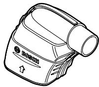
Note: While sawing, always use the deflection tube 24 or the dust/chip box 25 so that you will not be hit by thrown about chips.
The deflection tube 24 can be used with or without dust/chip extraction. Depending on the application, turn the deflection tube 24 in such a manner that you are not hit by chips and insert it firmly into the sawdust ejector 16.
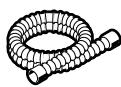
External Dust Extraction (see figure B)
Mount the vacuum hose 23 (accessory) on to the saw dust ejector 16. Connect the vacuum hose 23 to a vacuum cleaner (accessory). An overview for connecting to various vacuum cleaners can be found at the end of this manual.
The machine can be plugged directly into the receptacle of a Bosch all-purpose vacuum cleaner with remote starting control. The vacuum cleaner starts automatically when the machine is switched on.
The vacuum cleaner must be suitable for the material being worked.
When vacuuming dry dust that is especially detrimental to health or carcinogenic, use a special vacuum cleaner.
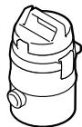
Integrated Dust Extraction (see figures C–E)
For smaller jobs, the dust/chip box 25 can be used with the slider 26 shut. For larger jobs, the slider 26 should be open so that the chips can fall out.
Insert the dust/chip box 25 firmly into the chip ejector 16.
Empty the dust/chip box 25 in time to maintain optimum efficiency.
To empty the dust/chip box 25, pull it off of the sawdust ejector 16. Press the slider 26 upward, turn the dust/chip box 25 aside and empty it.
Before reattaching, clean the connection sleeve of the dust/chip box 25.


Operation
Operating Modes
▶ Before any work on the machine itself, pull the mains plug.
Adjusting the Cutting Depth (see figure F)
▶ Adjust the cutting depth to the thickness of the workpiece. Less than a full tooth of the blade teeth should be visible below the workpiece.
Loosen the clamping lever 27. For a smaller cutting depth, pull the saw away from the base plate 12; for a larger cutting depth, push the saw toward the base plate 12. Adjust the desired cutting depth at the cutting-depth scale. Tighten the clamping lever 27 again.
Adjusting the Cutting Angle
Loosen the wing bolts 7 and 14. Tilt the saw sidewards. Adjust the desired measure on the scale 5. Tighten the wing bolts 7 and 14 again.
Note: For bevel cuts, the cutting depth is smaller than the setting indicated on the cutting-depth scale 28.
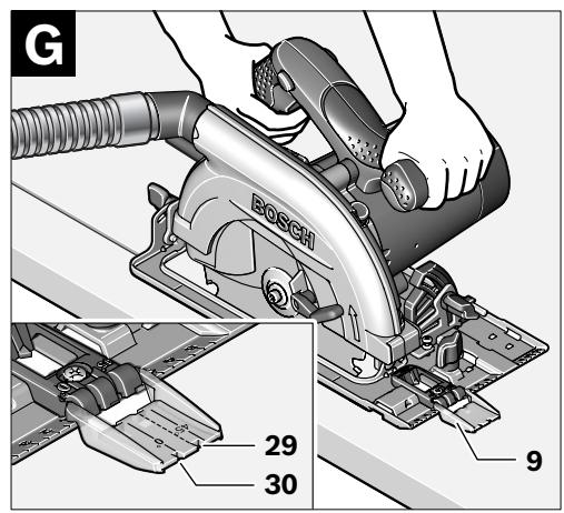
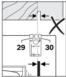
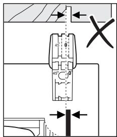
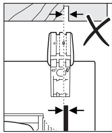
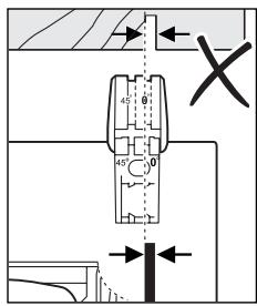
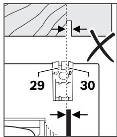
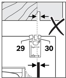
Cutting Marks (see figure G) (PKS 55 A/PKS 66 A/PKS 66 AF)
The “CutControl” 9 viewing window, which folds out to the front, is used for precise guiding of the circular saw alongside the cutting line on the workpiece. The “CutControl” 9 viewing window has a mark each for right-angled cuts and for 45° cuts.
The 0^ cutting mark (30) indicates the position of the saw blade for right-angled cuts. The 45^ cutting mark (29) indicates the position of the saw blade for 45^ cuts.
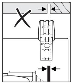
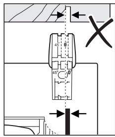
For precise cuts, position the circular saw against the workpiece as shown in the figure. It is best to carry out a trial cut.
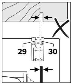
Cutting Marks (PKS 55)
The 0^ cutting mark (30) indicates the position of the saw blade for right-angled cuts. The 45^ cutting mark (29) indicates the position of the saw blade for 45^ cuts.
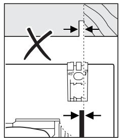

For precise cuts, position the circular saw against the workpiece as shown in the figure. It is best to carry out a trial cut.
Starting Operation
▶ Observe correct mains voltage! The voltage of the power source must agree with the voltage specified on the nameplate of the machine. Power tools marked with 230 V can also be operated with 220 V.
Switching On and Off
To start the machine, first push the lock-off button for the On/Off switch 1 and then press the On/Off switch 2 and keep it pressed.
To switch off the machine, release the On/Off switch 2.

26 | English
Note: For safety reasons, the On/Off switch 2 cannot be locked; it must remain pressed during the entire operation.
Working Advice
Protect saw blades against impact and shock.
Guide the machine evenly and with light feed in the cutting direction. Excessive feed significantly reduces the service life of the saw blade and can cause damage to the power tool.
Sawing performance and cutting quality depend essentially on the condition and the tooth form of the saw blade. Therefore, use only sharp saw blades that are suited for the material to be worked.
Sawing Wood
The correct selection of the saw blade depends on the type and quality of the wood and whether lengthway or crossway cuts are required.
When cutting spruce lengthways, long spiral chips are formed.
Beech and oak dusts are especially detrimental to health. Therefore, work only with dust extraction.
Sawing Non-ferrous Metals
Note: Use only a sharp saw blade that is suitable for non-ferrous metals. This ensures a clean cut and prevents blade binding.
Guide the switched on power tool against the workpiece and carefully start the cut. Continue the cut with low feed and without interruption.
When sawing profiles, always begin the cut from the narrow side; when sawing U-profiles, never start the cut from the open side. Support long profiles in order to avoid blade binding and kick-back of the power tool.
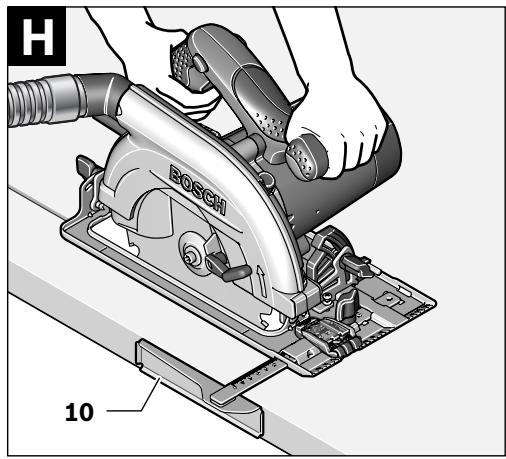
Sawing with Parallel Guide (see figure H)
The parallel guide 10 enables exact cuts along a workpiece edge and cutting strips of the same dimension.
Loosen wing bolt 8 and slide the scale of the parallel guide 10 through the guide in the base plate 12. Adjust the desired cutting width as the scale setting at the respective cutting mark 30 or 29; see Section “Cutting Marks”. Tighten wing bolt 8 again.
Sawing with Auxiliary Guide (see figure I)
For sawing large workpieces or straight edges, a board or strip can clamped to the workpiece as an auxiliary guide; the base plate of the circular saw can be guided alongside the auxiliary guide.
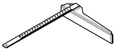
Sawing with Guide Rail (see figures J-L)
The guide rail 32 is used to carry out straight cuts.
The adhesive coating prevents the guide rail from slipping and protects the surface of the workpiece.
The guide rail 32 can be extended. For this, turn around both guide rails 32 by 180° and connect both guide rails 32 by inserting them. Press button 33 to lock the guide rails. To disassemble the guide rails, press the opposite button 33 and pull the guide rails 32 apart.
The guide rail 32 has two marks on the top side. The side with the “90°” mark is used for right-angled cuts, and the side with the “45°” mark is used for all other mitre cuts.
The rubber lip on the guide rail acts as a splinter guard for 90° and 45° cuts; it prevents fraying of the surface while sawing wooden materials.
Upon initial sawing, the rubber lip is adapted to your circular saw, and slightly cut off in this process.
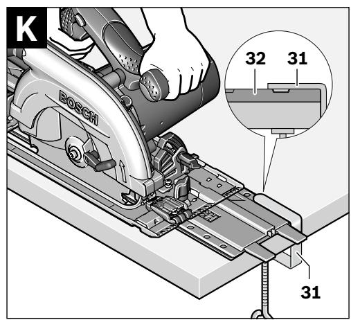
Note: On the workpiece side where the cut is being started, the guide rail 32 must always face flush against the workpiece, and may not project beyond it.
Should the guide rail 32 project beyond the workpiece end, do not rest the circular saw on the guide rail 32 without holding the circular saw. The guide rail 32 is made of plastic and cannot hold the circular saw.


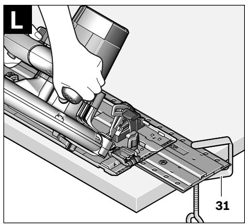
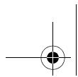
Fasten the guide rail 32 to the workpiece using the special screw clamps 31. Take care that the cam on the inside of the screw clamp 31 is seated in the corresponding recess of the guide rail 32.
Switch the machine on and guide it in the cutting direction applying moderate and steady feed.
Maintenance and Service
Maintenance and Cleaning
▶ Before any work on the machine itself, pull the mains plug.
▶ For safe and proper working, always keep the machine and ventilation slots clean.
The retracting blade guard must always be able to move freely and retract automatically. Therefore, always keep the area around the retracting blade guard clean. Remove dust and chips by blowing out with compressed air or with a brush.
Saw blades that are not coated can be protected against corrosion with a thin coat of acid-free oil. Before use, the oil must be removed again, otherwise the wood will become soiled.
Resin and glue residue on the saw blade produces poor cuts. Therefore, clean the saw blade immediately after use.
If the machine should fail despite the care taken in manufacturing and testing procedures, repair should be carried out by an after-sales service centre for Bosch power tools.
In all correspondence and spare parts order, please always include the 10-digit article number given on the type plate of the machine.
After-sales Service and Customer Assistance
Our after-sales service responds to your questions concerning maintenance and repair of your product as well as spare parts. Exploded views and information on spare parts can also be found under:
www.bosch-pt.com
Our customer service representatives can answer your questions concerning possible applications and adjustment of products and accessories.
Great Britain
Robert Bosch Ltd. (B.S.C.)
P.O. Box 98
Broadwater Park
North Orbital Road
Denham
Uxbridge
UB 9 5HJ
Tel. Service: +44 (0844) 736 0109
Fax: +44 (0844) 736 0146
E-Mail: boschservicecentre@bosch.com
Ireland
Origo Ltd.
Unit 23 Magna Drive
Magna Business Park
City West
Dublin 24
Tel. Service: +353 (01) 4 66 67 00
Fax: +353 (01) 4 66 68 88
Australia, New Zealand and Pacific Islands
Robert Bosch Australia Pty. Ltd.
Power Tools
Locked Bag 66
Clayton South VIC 3169
Customer Contact Center
Inside Australia:
Phone: +61 (01300) 307 044
Fax: +61 (01300) 307 045
Inside New Zealand:
Phone: +64 (0800) 543 353
Fax: +64 (0800) 428 570
Outside AU and NZ:
Phone: +61 (03) 9541 5555
www.bosch.com.au
Republic of South Africa
Customer service
Hotline: +27 (011) 6 51 96 00
28 | English
Gauteng - BSC Service Centre
35 Roper Street, New Centre
Johannesburg
Tel.: +27 (011) 4 93 93 75
Fax: +27 (011) 4 93 01 26
E-Mail: bsctools@icon.co.za
KZN - BSC Service Centre
Unit E, Almar Centre
143 Crompton Street
Pinetown
Tel.: +27 (031) 7 01 21 20
Fax: +27 (031) 7 01 24 46
E-Mail: bsc.dur@za.bosch.com
Western Cape - BSC Service Centre
Democracy Way, Prosperity Park
Milnerton
Tel.: +27 (021) 5 51 25 77
Fax: +27 (021) 5 51 32 23
E-Mail: bsc@zsd.co.za
Bosch Headquarters
Midrand, Gauteng
Tel.: +27 (011) 6 51 96 00
Fax: +27 (011) 6 51 98 80
E-Mail: rbsa-hq.pts@za.bosch.com
Disposal
The machine, accessories and packaging should be sorted for environmental-friendly recycling.
Only for EC countries:
Do not dispose of power tools into household waste!
According to the European Guideline 2002/96/EC for Waste Electrical and Electronic Equipment and its implementation into national
right, power tools that are no longer usable must be collected separately and disposed of in an environmentally correct manner.
Subject to change without notice.
Dr. Egbert Schneider Senior Vice President Engineering
Dr. Eckerhard Strötgen Head of Product Certification
ppa. Macau i.v. Nuoyen
Robert Bosch GmbH, Power Tools Division D-70745 Leinfelden-Echterdingen 08.03.2010
Montage

Robert Bosch (France) S.A.S.
Dr. Egbert Schneider Senior Vice President Engineering
Dr. Eckerhard Strötgen Head of Product Certification
ppa. Macena i.v. Nuoyen
Robert Bosch GmbH, Power Tools Division D-70745 Leinfelden-Echterdingen 08.03.2010
Montaje
Dr. Egbert Schneider Senior Vice President Engineering
Dr. Eckerhard Strötgen Head of Product Certification

Robert Bosch GmbH, Power Tools Division D-70745 Leinfelden-Echterdingen 08.03.2010
Montagem

Senior Vice President
Engineering
Dr. Eckerhard Strötgen
Head of Product
Certification

Robert Bosch GmbH, Power Tools Division
D-70745 Leinfelden-Echterdingen
08.03.2010
Montaggio
Senior Vice President
Engineering
Dr. Eckerhard Strötgen
Head of Product
Certification

Robert Bosch GmbH, Power Tools Division
D-70745 Leinfelden-Echterdingen
08.03.2010
Montage

Dr. Egbert Schneider Senior Vice President Engineering
Dr. Eckerhard Strötgen Head of Product Certification

Robert Bosch GmbH, Power Tools Division
D-70745 Leinfelden-Echterdingen
08.03.2010
Montering


Bosch Service Center
Telegrafvej 3
2750 Ballerup
Tel. Service Center: +45 (4489) 8855
Fax: +45 (4489) 87 55
E-Mail: vaerktoej@dk.bosch.com
Bortskaffelse
Dr. Egbert Schneider Senior Vice President Engineering
Dr. Eckerhard Strötgen Head of Product Certification

Robert Bosch GmbH, Power Tools Division D-70745 Leinfelden-Echterdingen 08.03.2010
Montage
Bosch Service Center
Telegrafvej 3
2750 Ballerup
Danmark
Tel.: +46 (020) 41 44 55
Fax: +46 (011) 18 76 91
Avfallshantering
Dr. Egbert Schneider Senior Vice President Engineering
Dr. Eckerhard Strötgen Head of Product Certification

Robert Bosch GmbH, Power Tools Division
D-70745 Leinfelden-Echterdingen
08.03.2010
Montering


Dr. Egbert Schneider Senior Vice President Engineering
Dr. Eckerhard Strötgen Head of Product Certification

Robert Bosch GmbH, Power Tools Division D-70745 Leinfelden-Echterdingen 08.03.2010
Asennus

Dr. Egbert Schneider Senior Vice President Engineering
Dr. Eckerhard Strötgen Head of Product Certification

Robert Bosch GmbH, Power Tools Division
D-70745 Leinfelden-Echterdingen
08.03.2010
Συναρμολόγηση
Dr. Egbert Schneider Dr. Eckerhard Strötgen Senior Vice President Head of Product Engineering Certification

Robert Bosch GmbH, Power Tools Division D-70745 Leinfelden-Echterdingen 08.03.2010
Montaj
Bosch San. ve Tic. A.S.
Ahi Evran Cad. No:1 Kat:22
Polaris Plaza
80670 Maslak/Istanbul
natural_image
Technical line drawing of a mechanical assembly with mounting holes and clamping brackets (no text or symbols)2 609 225 732
natural_image
Technical line drawing of a mechanical tool with a ruler and bracket (no text or symbols)2 608 005 018
2 609 225 731
natural_image
Technical line drawing of a mechanical device with no visible text or symbols

∅ 35 mm
3 m 2 600 002 149
5 m 1 610 002 150
PAS 11-21
PAS 12-27
PAS 12-27 F

152 |
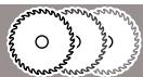
optiline WOOD


speedline WOOD


MULTI MATERIAL


CONSTRUCT WOOD