HNU61422B - Basket BEKO - Free user manual and instructions
Find the device manual for free HNU61422B BEKO in PDF.

User questions about HNU61422B BEKO
0 question about this device. Answer the ones you know or ask your own.
Ask a new question about this device
Download the instructions for your Basket in PDF format for free! Find your manual HNU61422B - BEKO and take your electronic device back in hand. On this page are published all the documents necessary for the use of your device. HNU61422B by BEKO.
USER MANUAL HNU61422B BEKO
natural_image
Simple line icon of a chimney emitting steam (no text or symbols)HNU 61422 B
EN - PL - ET - LV - LT - FR - NL - DE - SK - CS
CONTENTS
| ENGLISH | 3-16 |
| POLSKI | 17-32 |
| EESTI | 33-45 |
| LATVIEŠU | 46-58 |
| LIETUVIŲ K | 59-72 |
| FRANÇAIS | 73-87 |
| NEDERLANDS | 88-102 |
| DEUTSCH | 103-118 |
| SLOVENSKÝ | 119-132 |
| ČESKY | 133-146 |
Please read this user manual first!
Dear Valued Customer,
Thank you for preferring this Beko appliance. We hope that you get the best results from your appliance which has been manufactured with high quality and state-of-the-art technology. For this reason, please read this entire user manual and all other accompanying documents carefully before using the appliance and keep it as a reference for future use. If you handover the appliance to someone else, give the user manual as well. Follow the instructions by paying attention to all the information and warnings in the user manual.
Remember that this user manual may also apply to other models. Differences between models are explicitly described in the manual.
Meanings of the Symbols
Following symbols are used in various sections of this user manual:

Important information and useful hints about usage.

WARNING: Warnings against dangerous situations concerning the security of life and property.
WARNING: Warning for danger of fire.
WARNING: Warning for electric shock.
1 Important safety and environmental instructions
1.1 General Safety
Important Safety Instructions Read Carefully And Keep For Future Reference This section contains safety instructions that will help protect from risk of fire, electric shock, exposure to leak microwave energy, personal injury or property damage. Failure to follow these instructions shall void any warranty.
•Beko products comply with the applicable safety standards; therefore, in case of any damage on the appliance or power cable, it should be repaired or replaced by the dealer, service center or a specialist and authorized service alike to avoid any danger. Faulty or unqualified repair work may be dangerous and cause risk to the user.
•This appliance is intended
to be used in household and similar applications such as:
-Staff kitchen areas in shops, offices and other working environments;
-Farm houses
-By clients in hotels, and other residential type environments;
-Bed and Breakfast type environments.
- Operate the appliance for its intended purpose only as described in this manual.
•The manufacturer cannot be held liable for damages resulting from improper installation or misuse of the product.
•This appliance can be used by children aged from 8 years and above and persons with reduced physical, sensory or mental capabilities or lack of experience and knowl-
1 Important safety and environmental instructions
edge if they have been given supervision or instruction concerning use of the appliance in a safe way and understand the hazards involved.
•Children shall not be allowed play with the appliance. Cleaning and user maintenance shall not be made by children without supervision.
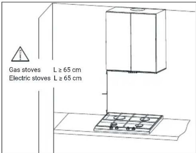
•The minimum distance between the supporting surface for the cooking vessels on the hob and the lowest part of your product must be at least 65 cm.
- If the instructions for installation for the gas hob specify a greater distance, this has to be taken into account.
- Make sure that your mains power supply complies with the information supplied on the rating plate of the appliance.
- Never use the appliance if the power cable or the appliance itself is damaged.
- Prevent damage to the power cable by not squeezing, bending, or rubbing it on sharp edges. Keep the power cable away from hot surfaces and naked flame.
- Use the appliance with a grounded outlet only.
WARNING: Do not connect the appliance to the mains until the installation is fully complete.
- Place the appliance in a way so that the plug is always accessible.
- Do not touch the lamps if they have operated for a long time. They can burn your hands since they will be hot.
- Follow the regulations set out by competent authorities on discharge of the exhaust air (this warning is not applicable for use
1 Important safety and environmental instructions
without flue).
- Operate your appliance after putting a pot, pan etc. on the hob. Otherwise, high heat may cause deformation in some parts of your product.
- Turn off the hob before taking the pot, pan etc. from it.
- Do not leave hot oil on the hob. Pans with hot oil may cause self combustion.
- Pay attention to your curtains and covers since oil may catch fire while cooking food such as fries.
- Grease filter must be cleaned at least monthly. Carbon filter must be replaced at least every 3 months.
- Product shall be cleaned accordance with user manual. If cleaning was not carried out in accordance with user manual, there may be fire risk.
- Do not use non-fire-resist-
ant filtering materials in- stead of the current filter.
- Only use the original parts or parts recommended by the manufacturer.
- Do not operate the product without the filter and do not remove the filters while the product is running.
• In the event of be started any flame, de-energize your product and cooking appliances.
• In the event of be started any flame, cover the flame and never use water to extinguish.
- Unplug the appliance before each cleaning and when the appliance is not in use.
•The negative pressure in the environment should not exceed 4 Pa (4x10 bar) while the hood for electric hob and appliances running on another type of energy but electricity op-
1 Important safety and environmental instructions
erate simultaneously.
•In the environment where the appliance is being used, the exhaust of devices running on fuel oil or gas, such as room heater must be absolutely isolated or device must be hermetical type.
- When connecting the flue, use pipes with a diameter of 120 or 150 ~mm . Pipe connection must be as short as possible and have as few elbows as possible.
- Danger of choking! Keep all the packaging materials away from children.
CAUTION: Accessible parts may become hot when used with cooking appliances.
•The product outlet must not be connected to air channels that include other smoke.
•The ventilation in the room may be insufficient when the hood for electric hob
is used simultaneously with the devices operating on gas or other fuels (this may not apply to appliances that only discharge the air back into the room).
- Objects placed on the product may fall. Do not place any objects on the product. - Do not flambe under the your product.
WARNING: Before installing the Hood, remove the protective films.
- Never leave high naked flames under the hood when it is in operation
- Deep fat fryers must be continuously monitored during use: overheated oil can burst into flames.
1.2 Compliance with the WEEE Directive and Disposing of the Waste Product:
This product complies with EU WEEE Directive (2012/19/EU). This product bears a classification symbol for waste electrical and electronic equipment (WEEE).
1 Important safety and environmental instructions
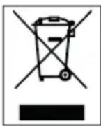
This symbol indicates that this product shall not be disposed with other household wastes at the end of its service life. Used device must be returned to offical collection point for recycling of electrical and electronic devices. To find these collection systems please contact to your local authorities or retailer where the product was purchased. Each household performs important role in recovering and recycling of old appliance. Appropriate disposal of used appliance helps prevent potential negative consequences for the environment and human health.
1.3 Compliance with RoHS Directive
The product you have purchased complies with EU RoHS Directive (2011/65/EU). It does not contain harmful and prohibited materials specified in the Directive.
1.4 Package Information
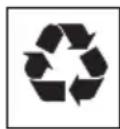
Packaging materials of the product are manufactured from recyclable materials in accordance with our National Environment Regulations. Do not dispose of the packaging materials together with the domestic or other wastes. Take them to the packaging material collection points designated by the local authorities.
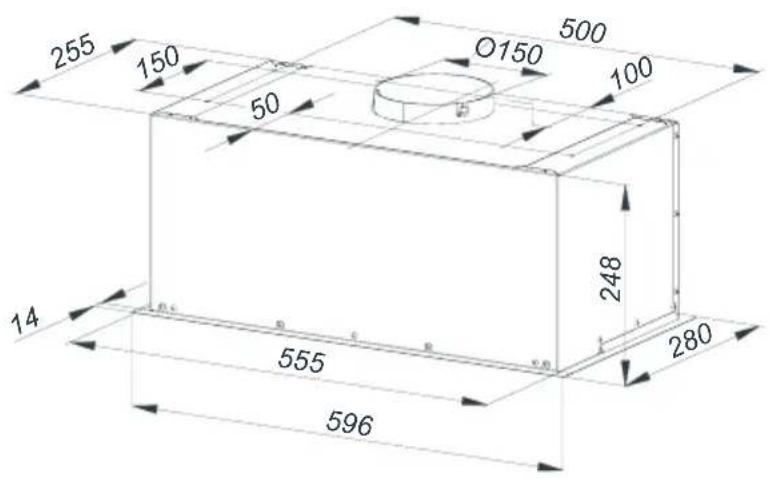
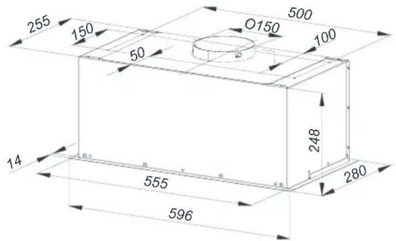
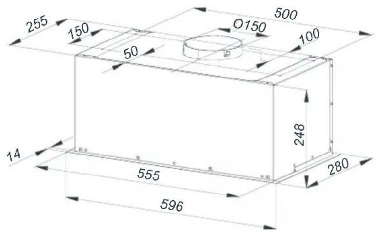
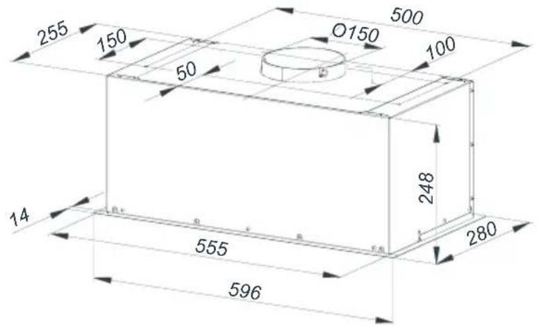
2 General appearance
2.1 Overview
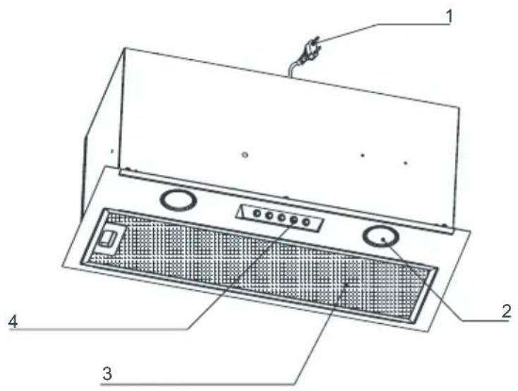
- Power cord
- Lighting
- Grease filter
- Mechanical control
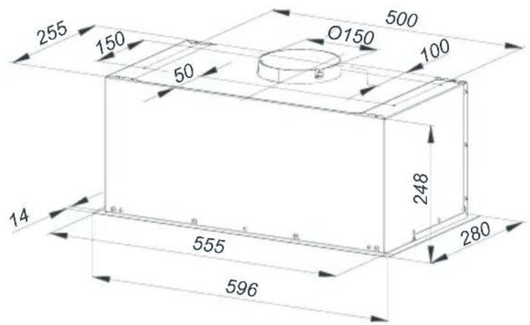
2.2 Technical data
| Model HNU 61422 B | |
| Supply voltage and frequency | 220-240 V 50 Hz |
| Lamp power | 2x3 W |
| Motor power | 115 W |
| Air flow – 3. Level 415 m3/h | |
| Motor insulation class class F | |
| Insulation class class II |
3 Using the appliance
3.1 Use of the rocker switch
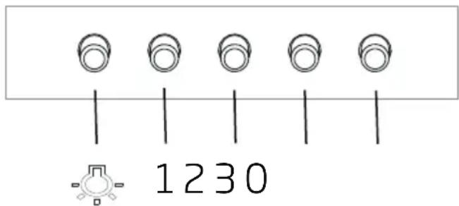
The hood is equipped with a mechanical control.
- Pressing the "0" - disables the hood.
- Pressing the "1" - to turn the hood with a minimum speed.
- Pressing the "2" - turns the hood with an average speed.
- Pressing the "3" - turns the hood at maximum speed.
- Press the button to turn on the lights. Repeat pressing the button to turn off the lighting.
3.2 Energy efficient usage
- When using your appliance, adjust the speed settings according to vapour and odour intensity, in order to save energy.
- Use low speeds (1-2) under normal conditions, and high speed (3) and boost mode for intense odour and vapour.
- The hood is equipped with lamps in order to illuminate the cooking area.
- Using them for environmental lighting shall cause unnecessary energy expenditure and insufficient lighting.
- For your device to consume less energy, run it at a low speed level.
- Your device will reduce energy consumption as it will run more efficiently when you provide sufficient air intake to it.
- Set your device to the intense suction power level before the formation of steam, in cases where you know that the dense steam will occur. So, you reduce energy consumption by using your device for a shorter time as it will have a sufficient air intake.
- Keep the lids of the cookware closed to reduce the steam evolving.
3.3 Operating the Hood
- Hood is equipped with a motor having various speed settings.
- For a better performance, we advise you to use low speeds in normal conditions, and high speeds when smell and vapors are intensified.
- You can start the hood by pressing the desired speed level key.(1,2,3)
- You can illuminate the cooking area by pressing the light key. (-)
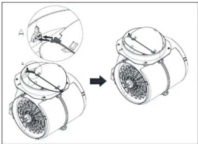
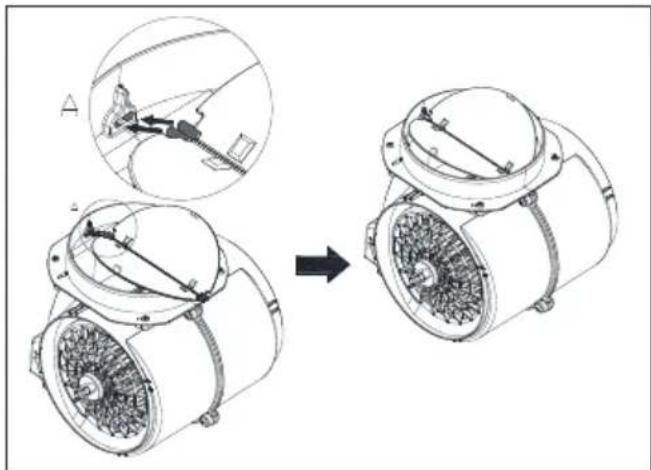
3.4 Lamp replacement

- Before replacing the light bulbs, disconnect the power supply of the hood.
- Do not touch the light bulbs when they are hot.
- Be careful not to touch the replaced light bulb directly with hands.

You may procure lamps from Authorised Service Agents.
Disconnect the hood from the mains supply. This appliance is equipped with 3 W spot LED lamps.
3 Using the appliance
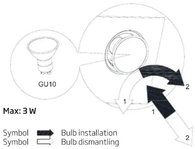
| Lamp | 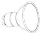 |
| Bulb power 3 W | |
| Holder/Socket GU10 | |
| Bulb voltage 230 V | |
| ILCOS Code DR/F-3-2 | 30-GU10-50 |
| Size 50 mm | |
| Luminous flux 260 lm | |
| Correlated colour temperature | 3000 K |
This product contains a light source of energy efficiency class "F".
3.5 Operation with chimney connection
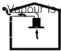
extracted through the flue duct, which is fastened to the connection head on the hood.
- The diameter of the flue duct must be the same as the connection ring. In horizontal settings, the pipe has to have a slight upward slope (around 10^ ) so that the air can exit the room easily.
3.6 Operation without chimney connection
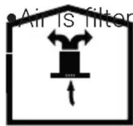
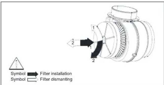
ed through the carbon filter and recircu- lated in the room. Carbon filter is used when it is im- possible to use a flue in
the house.
- In flueless use, remove the flaps inside the flue adapter.
- Remove the aluminum grease filter. To install the carbon filter, fit the filter to the tabs by centring it on the plastic piece on both sides of the fan body. tighten it by turning right or left.
-Replace aluminum grease filter.
4 Cleaning and maintenance
The device should be cleaned and maintained regularly. Failure to keep the device clean will adversely affect the service life of the device. For cleaning and maintenance, follow the instructions stated in the manual.

Before cleaning and maintenance, unplug the product or turn off the switch.
Non-compliance with the provisions associated with the cleaning of the device and replacement of the filters may result in a risk of fire. Therefore, it is recommended to follow the guidelines stated here. The manufacturer is not responsible for the engine damages or fires originating from the improper use.
Clean using only a cloth dampened with a neutral liquid detergent. Do not use abrasive products or alcohol.
4.1 Cleaning of Grease Filter
This filter captures oil particles in the air. You are recommended to clean your filter every month under normal usage conditions. First remove the grease filters for this process. Wash the filters with liquid detergent and rinse them with water and install them back after they get dry. Aluminium grease filters may get discolored as they are washed; this is normal and you don't need to change your filter.

You may wash your grease filter in the dishwasher.

CAUTION: In case of normal use, clean your filter once in a month.
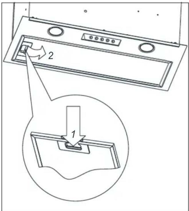
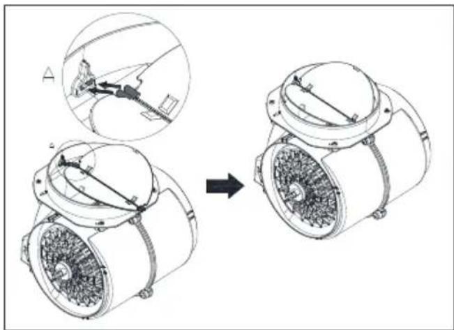
4.2 Changing of Carbon Filter (Air Circulation Mode)
The hood can be fitted with an active carbon filter. The carbon filter is applied only in case the hood is not connected to the vent duct.
4 Cleaning and maintenance
natural_image
Technical illustration of a mechanical assembly showing two views of a motor or fan with internal components, no text or symbols present.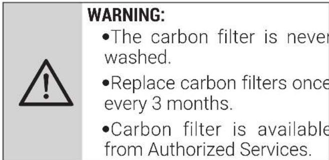
5 Setting up the device

WARNING: Before starting the installation, read the safety information on user manual.

WARNING: Failure to install with screws and stabilizers in accordance with these instructions may result in electric shock.
For the installation of the hood, please contact the nearest Authorized Service.
It is the customer's responsibility to prepare the location and electrical installation of the hood.
5.1 Position of the appliance
- Distance between the cooker and the cooker hood must be considered prior to assembly. This distance should be 65 cm.
- Distance must be measured from the surface of grate for gas cookers, from surface of glass for electric cookers.
5 Setting up the device
5.2 Installation accessories
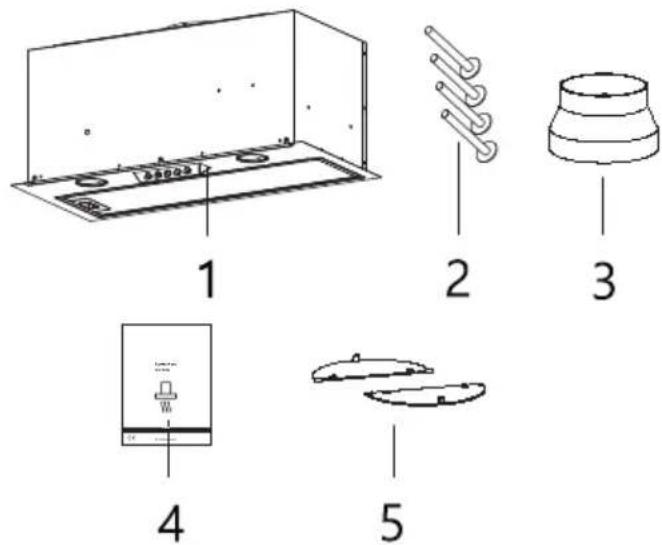
- Hood
- 4x3,9x13 mm Screw
- ∅150/ ∅120 plastic adapter
- User Manual
- Blower flaps
5.3 Installation of the device
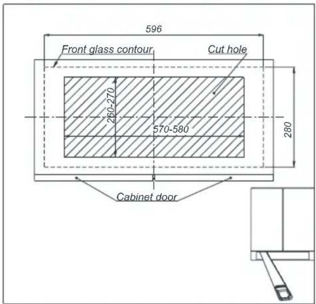
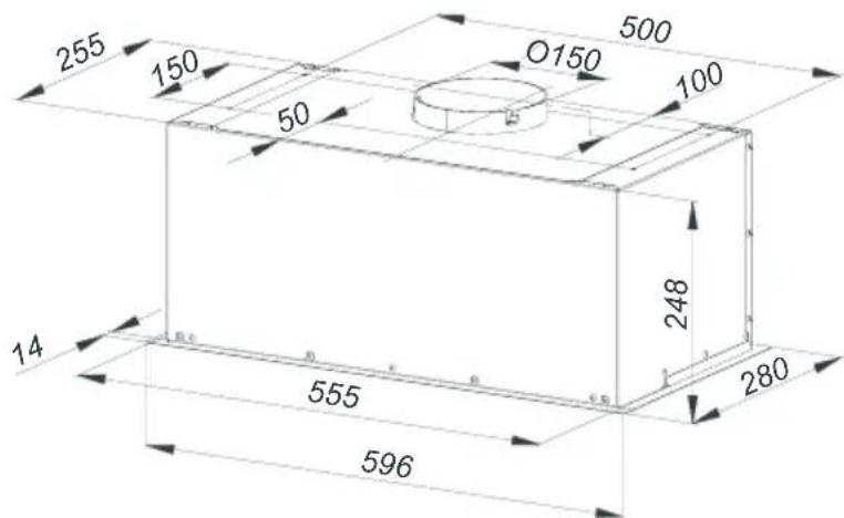
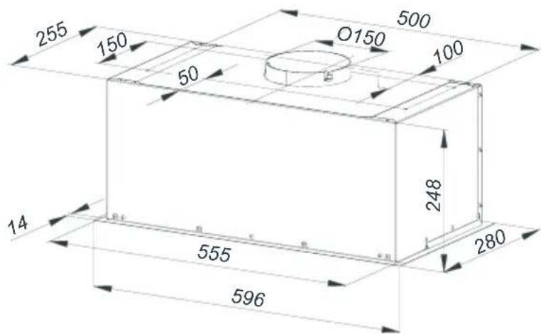
- Prepare the cabinet for the installation of the hood, cut the hole in the bottom of the cabinet in accordance with the drawing.
Preparation of the cabinet
- Remove the grease grease filters
- Carefully insert the hood into the previously cut hole, hold the hood with one hand or ask an additional person for help. Screw in the bolts / screws choosing one mounting variant a-fixing to the top of the cabinet, b- fixing to the side of the cabinet.
Installation of the hood - top mounting version
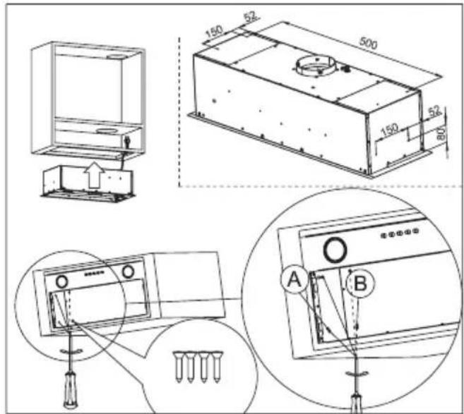
- When attaching the hood to the top of the cabinet, prepare holes in the shelf of the cabinet according to the dimensions shown in the drawing. However, in the case of a side variant, the side skirts should be prepared as described in
5 Setting up the device
Installation of the hood - side mounting version
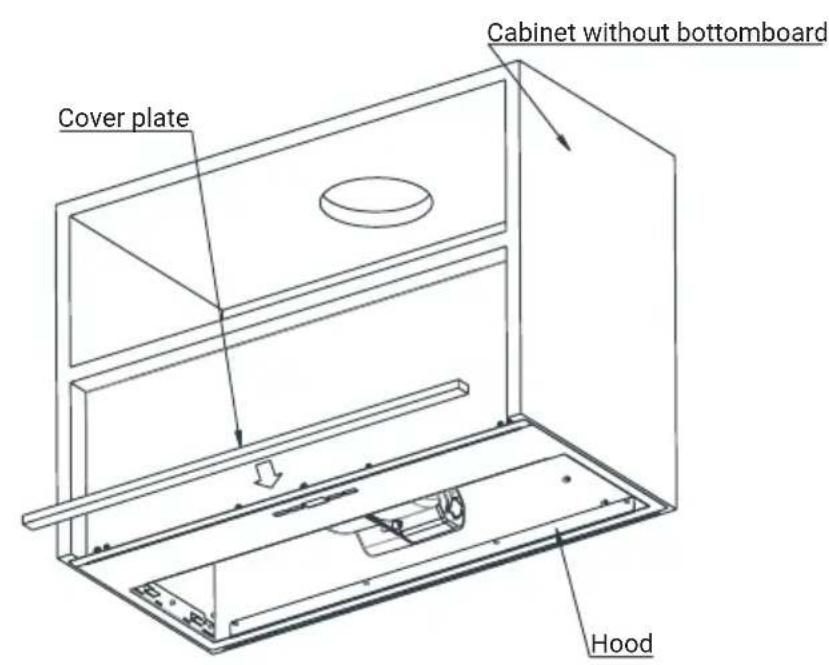

The installation of an additional masking strip applies only to cabinets without a bottom
5.4 Electrical connections
The network voltage shall correspond to the voltage indicated at the plate placed inside the hood. If the hood is equipped with a plug, insert it into the socket complying with the applicable requirements, and located in the easily accessible place. If the hood is not equipped with a plug, the hood installations shall be performed by a person having the required authorizations (such as electrician).
5.5 Storage
- If you do not intend to use the appliance for a long time, please store it carefully.
-
Please make sure that the appliance is unplugged, cooled down and totally dry.
-
Store the appliance in a cool and dry place.
- Keep the appliance out of the reach of children
5.6 Handling and transportation
- During handling and transportation, carry the appliance in its original packaging. The packaging of the appliance protects it against physical damages.
- Do not place heavy loads on the appliance or the packaging. The appliance may be damaged.
- Dropping the appliance will render it non-operational or cause permanent damage.
6 Troubleshooting
| Troubleshooting Root cause Help | ||
| Appliance is not working. | Check your fuses. Fuse | may be blown, inspect and restore it. |
| Appliance is not working. | Check the electrical connection. | Mains voltage shall be between 220 and 240 V. |
| Appliance is not working. | Check the electrical connection. | Check if other appliance in your kitchen operate. |
| Illumination light does not operate. | Check the electrical connection. | Mains voltage shall be between 220 and 240 V. |
| Illumination light does not operate. | Inspect the lamp switch. | Lamp switch shall be at “on” position. |
| Illumination light does not operate. | Inspect the lamps. The lamps of the appliance shall illuminate. | |
| Air inlet of the appliance is inadequate. | Inspect the grease filter. | Under normal operating conditions, grease filter shall be cleaned at least once in a month. |
| Air inlet of the appliance is inadequate. | Check the air discharge chimney. | The air discharge chimney shall be at “on” position. |
| Air inlet of the appliance is inadequate. | Inspect the carbon filter. | The filters of the appliances with carbon filters shall be replaced once in every 3 months under normal conditions. |

natural_image
Simple line drawing of a box inside a house shape with arrows indicating direction (no text or symbols)
natural_image
Technical line drawing of a mechanical assembly showing a disassembly process with labeled components (no text or symbols present)

natural_image
Technical illustration of a mechanical assembly showing a disassembly process with labeled components (no text or symbols present)HOIATUS:


natural_image
Technical line drawing of a mechanical assembly showing a disassembly process with labeled components (no text or symbols present)UZMANIBU


natural_image
Technical illustration of a mechanical assembly showing two views of a motor or fan with internal components and a directional arrow (no text or symbols present)DÉMESIO


natural_image
Diagram showing a mechanical assembly before and after transformation, with no visible text or symbols.
ATTENTION
- Netsnoer
- Verlichting
- Aluminium vetfilter
- Bedieningspaneel
Symbol Symbol

Bulb installation
Bulb dismantling

natural_image
Technical illustration of a mechanical assembly showing a disassembly process with labeled components (no text or symbols present)
OPGELET
Symbol Symbol

Bulb installation Bulb dismantling

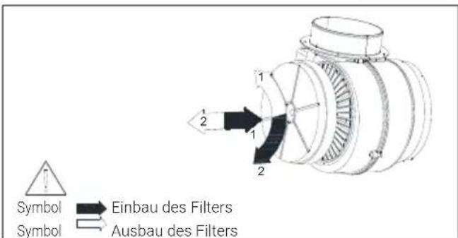
4.2 Changing of Carbon Filter (Air Circulation Mode)
The hood can be fitted with an active carbon filter. The carbon filter is applied only in case the hood is not connected to the vent duct.
natural_image
Technical illustration of a mechanical assembly showing two views of a motor with internal components and a directional arrow (no text or symbols)WARNUNG

Symbol Symbol

Bulb installation
Bulb dismantling
| Lampa | 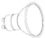 |
| Moc | 3 W |
| Zásuvka | GU10 |
| Napätie | 230 V |
| Kód ILCOS | DR/F-3-230-GU10-50 |
| Rozmer | 50 mm |
| Svetelný tok | 260 lm |
| Súvisiaca teplota farby | 3000 K |
4 Čistenie a údržba
natural_image
Technical illustration of a mechanical assembly showing two stages of assembly, with no visible text or symbols.
VÝSTRAHA
5.1 Umiestnenie spotrebiča

4 Čištění a údržba
natural_image
Technical illustration of a mechanical assembly showing two views of a motor with rotating components and a close-up view of the mechanism (no text or symbols present)