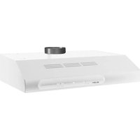
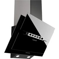
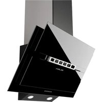
Classic ECH 930 WH - Range hood Elba - Free user manual and instructions
Find the device manual for free Classic ECH 930 WH Elba in PDF.


| Brand | Elba |
| Model | Classic ECH 930 WH |
| Product Type | Wall-mounted cooker hood |
| Width | 90 cm |
| Minimum safety distance from hob | 65 cm (higher if specified by the hob) |
| Electrical supply | 220-240 V / 50-60 Hz (check rating plate) |
| Electrical class | Class I or II (depending on model, check plate) |
| Lighting power | 28W-40W lamp (halogen or similar) |
| Number of motor speeds | Multiple speeds (adjustable via switches) |
| Usage version | External evacuation or recirculation (with charcoal filter) |
| Exhaust connection diameter | 100 mm or 120 mm (depending on model) |
| Grease filter | Multilayer metal, washable in dishwasher or washing machine |
| Active carbon filter (recirculation) | Replacement every 3 months (depending on use) |
| Grease filter maintenance | Monthly wash with warm water and neutral detergent or in dishwasher |
| Replacement frequency of disposable grease filter | Every 2 months (if thin disposable filter) |
| External cleaning | Warm water and neutral liquid detergent (no abrasive products) |
| Safety | Do not flambé under the hood, monitor frying, adequate ventilation if simultaneous extraction with combustion appliances |
| Installation | Wall-mounted or under-cabinet, by a competent technician |
| Spare parts | Grease filters, charcoal filters, lamps |
| Repairability | Replacement of lamps and filters by user; for cable or motor, contact after-sales service |
Frequently Asked Questions - Classic ECH 930 WH Elba
User questions about Classic ECH 930 WH Elba
0 question about this device. Answer the ones you know or ask your own.
Ask a new question about this device
Download the instructions for your Range hood in PDF format for free! Find your manual Classic ECH 930 WH - Elba and take your electronic device back in hand. On this page are published all the documents necessary for the use of your device. Classic ECH 930 WH by Elba.
USER MANUAL Classic ECH 930 WH Elba
SAFETY INFORMATION......12
GENERAL INFORMATION - SAFETY WARNINGS 15
INSTALLATION....16
USE - MAINTENANCE 17
SOMMAIRE
FR
CONSIGNES DE SÉCURITÉ....20
GENERALITES - CONSEILS CONCERNANT LA SECURITE....23
INSTALLATION....24
UTILISATION - ENTRETIEN 25
INHALTSVERZEICHNIS
DE
natural_image
Line drawing of a hand holding a tool, no text or symbols present| Lampada | Assorbimento (W) | Attacco Voltaggio | (V) Dimensione (mm) | Codice ILCOS | |
| 28 E14 220 | -240 104 x 35 | HSGSB/C/UB-28-220/240-E14 | |||
| 28 | E14 | 230 | 85x25HDG-28-230-E14-25 | ||
| 20 G4 12 33 x 9 HSG/C/UB-20-12-G4 | |||||
 | 35 | GU10 | 230 | 51 x 50,7 | HAGS-35-230-GU10-51/40 |
| 50 | GU10 | 230 | 51 x 50,7 | HAGS-35-230-GU10-51/20 | |
 | 20 | GU4 | 12 | 40 x 35 | HRGS-20-12-GU4-35/30 |
| 20 | GU5.3 | 12 | 46 x 51 | HRGS-20-12-GU5.3-50/10 | |
| 16 | G13 | 95 | 720 x 26 | FD-16/40/1B-E-G13-26/720 | |
| 18 | G13 | 57 | 589,8 x 26 | FD-18/40/1B-E-G13-26/600 | |
| 9 | G23 | 60 (lampada)220-240 (starter) | 167 x 28 | FSD-9/27/1B-I-G23 | |
| 11 | G23 | 91 (lampada)220-240 (starter) | 235,8 x 28 | FSD-11/40/1B-I-G23 | |
ILLUMINAZIONE
natural_image
Line drawing of a hand using a tool to adjust or install a mechanical component, no text or symbols present| Lampada | Assorbimento (W) | Attacco | Voltaggio | (V) | Dimensione (mm) | Codice ILCOS | |
| [x000x] | 4 | E14 220 | - | 240 | 107 x 37 | DRBB/F-4-220-240-E14-35/100 | |
 | 5 | GU10 230 | 52 x 50 | DRPAR-5/840-220/240-GU10-35/36DRPAR-5/830-220/240-GU10-35/36 |

For your safety and correct operation of the appliance, read this manual carefully before installation and use. Always keep these instructions with the appliance even if you move or sell it. Users must fully know the operation and safety features of the appliance.

The wire connection has to be done by specialized technician.
- The manufacturer will not be held liable for any damages resulting from incorrect or improper installation.
- The minimum safety distance between the cooker top and the extractor hood is 650 mm (some models can be installed at a lower height, please refer to the paragraphs on working dimensions and installation).
- If the instructions for installation for the gas hob specify a greater distance, this must be respected.
- Check that the mains voltage corresponds to that indicated on the rating plate fixed to the inside of the hood.
- Means for disconnection must be incorporated in the fixed wiring in accordance with the wiring rules.
- For Class I appliances, check that the domestic power supply guarantees adequate earthing.
- Connect the extractor to the exhaust flue through a pipe of minimum diameter 120 mm. The route of the flue must be as short as possible.
• Regulations concerning the discharge of air have to be fulfilled. - Do not connect the extractor hood to exhaust ducts carrying combustion fumes (boilers, fireplaces, etc.).
- If the extractor is used in conjunction with non-electrical appliances (e.g. gas burning appliances), a sufficient degree of aeration must be guaranteed in the room in order to prevent the backflow of exhaust gas. When the cooker hood is used in conjunction with appliances supplied with energy other than electric, the negative pressure in the room must not exceed 0,04 mbar to prevent fumes being drawn back into the room by the cooker hood.
- The air must not be discharged into a flue that is used for exhausting fumes from appliances burning gas or other fuels.
- If the supply cord is damaged, it must be replaced from the manufacturer or its service agent.
- Connect the plug to a socket complying with current regulations, located in an accessible place.
- With regards to the technical and safety measures to be adopted for fume discharging it is important to closely follow the regulations provided by the local authorities.
⚠ WARNING: Before installing the Hood, remove the protective films.
- Use only screws and small parts in support of the hood.
⚠ WARNING: Failure to install the screws or fixing device in accordance with these instructions may result in electrical hazards.
- Do not look directly at the light through optical devices (binoculars, magnifying glasses...).
- Do not flambè under the range hood; risk of fire.
- This appliance can be used by children aged from 8 years and above and persons with reduced physical, sensory or mental capabilities or lack of experience and knowledge if they have been given supervision or instruction concerning use of the appliance in a safe way and understand the hazards involved. Children shall not play with the appliance. Cleaning and user maintenance shall not be made by children without supervision.
- Children should be supervised to ensure that they do not play with the appliance.
- The appliance is not to be used by persons (including children) with reduced physical, sensory or mental capabilities, or lack of experience and knowledge, unless they have been given supervision or instruction.
▲ Accessible parts may become hot when used with cooking appliances.
- Clean and/or replace the Filters after the specified time period (Fire hazard). See paragraph Care and Cleaning.
- There shall be adequate ventilation of the room when the range hood is used at the same time as appliances burning gas or other fuels (not applicable to appliances that only discharge the air back into the room).
- The symbol on the product or on its packaging indicates that this product may not be treated as household waste. Instead it shall be handed over to the applicable collection point for the recycling of electrical and electronic equipment. By ensuring this product is disposed of correctly, you will help prevent potential negative consequences for the environment and human health, which could otherwise be caused by inappropriate waste handling of this product. For more detailed information about recycling of this product, please contact your local city office, your household waste disposal service or the shop where you purchased the product.

"In case of replacement with halogen lamp use only self-shielded tungsten halogen lamps or self-shielded metal halide lamps."
GENERAL INFORMATION
This canopy hood is designed to be fixed to any rigid vertical surface, over a gas or electric hotplate and can be used either in the extraction mode (ducted to the outside) or in the recirculation mode (internal recycling). All cookers hood perform better when used in extraction mode. During winter time it may be convenient to use the hood in the recycling mode to avoid heat loss from the kitchen.
Before starting the installation, consideration should be given to the difficulties that can be found during installation. The installation work must be undertaken by a qualified and competent person in conformity to the rules concerning the evacuation of contaminated air.
The manufacturer disclaims all liability for any damage or injury caused as a result of not following the instructions for installation contained in the following text.
1 - SAFETY WARNINGS
1.1 - When used in the extraction mode, the cooker hood ducting must not be connected to a flue which is used for exhausting fumes from appliances supplied with energy other than electric, such as a central heating flue or water heating flue.
1.2 - Before connecting to the mains supply ensure that the mains voltage corresponds with the voltage on the rating plate inside the hood.
1.3 - Connect the cookerhood to the mains via a double poled switch which has 3mm clearance between the contacts.
1.4 - For cooker hoods featuring an earth cable, make sure the electric plant of your house is correctly earthed.
1.5 - Appliance in class II are provided with a double insulation; therefore do not connect them through earthed plugs but through a double poled plugs.
1.6 - When installed, the hood must be positioned at least 65cm above the hotplate.
Warning: Failure to install the screws or fixing device in accordance with these instructions may result in electrical hazards.
1.7 - Never do flambé cooking under this cooker hood.
1.8 - Never leave frying pans unattended during use as overheated fat and oil may catch fire.
1.9 - Before carrying out any kind of maintenance or cleaning, disconnect the hood from the mains supply.
1.10- If the room where the cooker hood is to be used contains a fuel burning appliance such as a central heating boiler then this must be of the room sealed or balanced flue type. If other types of flue or appliance are fitted, ensure that there is an adequate supply of air into the room. When the cooker hood is used in conjunction with appliances supplied with energy other than electric, the negative pressure in the room must not exceed 0,04 mbar to prevent fumes being drawn back into the room by the cooker hood.
1.11- The appliance must be positioned so that the plug is accessible.
1.12- If the supply cord is damaged, it must be replaced by a special cord or assembly available from the manufacturer or its service agent.
1.13- This appliance is not intended for use by persons (including children) with reduced physical, sensory or mental capabilities, or lack of experience and knowledge, unless they have been given supervision or instruction concerning use of the appliance by a person responsible for their safety.
1.14- Children should be supervised to ensure that they do not play with the appliance.
2 - INSTALLATION INSTRUCTIONS
Some installation systems require the opening and removal of the metal grille panel.
2.1 - Instructions for opening and removing the metal grille panel
To open the grille panel, press inwardly on the two slider catches at each side of the grille panel and the grille will pivot down.
To remove the metal grille, pull forward on the right hand side so that the hinge pin on the back of the grille will be released from the slot in the side of the casing.
2.2 - Wall cabinet fixing
a - Predrilled wall cabinet: fix the hood onto the wall cabinet base panel using the four screws 4.2 x 45 mm (supplied with the fixing kit).
It is not necessary to open the metal grille.
b - No predrilled wall cabinet:
b.1 - If the hood is provided with a paper fixing template, follow the instructions.
b.2 - If the hood is not provided with a paper fixing template, position the hood on the wall cabinet base panel and pilot drill the 3.5 x 16 mm screws (not supplied with the fixing kit) from the inside onto the wood.
2.3 - Wall mounting
a - Drill two ∅ 8 mm holes on the wall using the paper template, insert two rawl plugs and two 4.2 x 44,4 mm screws leaving 5 mm untightened. Open the metal grille panel, hook the hood on and fully tighten the screws.
b - If the hood is not provided with a paper fixing template, drill two 8 mm holes (see draw.), insert the plugs and screws, proceeding as directed under paragraph a.
c - For wall mounting using wallbrackets (optional), follow the instructions of the fixing template.
d - Pay attention to the safety regulation of point 1.6.
2.4 - Choice of operating mode
a - Evacuation mode
To check that the hood is set up for evacuation, open the grille panel and make sure that the conversion lever or the change-over knob on the centrifugal unit is in the DUCTING position. The charcoal filter is not required.
For ducting to the outside, the hood is supplied with a rear and top outlet. A flange spigot of 100 mm diameter (120 mm in certain models) is usually fitted on the top outlet and a blanking plug on the rear outlet. If you choose to duct the hood from the rear of the casing, you should invert the position of the flange and of the blanking plug. Pay attention to the safety regulation 1.1.
b - Internal recirculation mode
To check that the hood is set up for recycling, open the grille panel and make sure that the conversion lever or the change-over knob on the centrifugal unit is in the RECYCLING position.
The charcoal filter is to be fitted. To fit the charcoal filter, support the filter with one hand and turn the thumb screw through the centre of the charcoal filter. If the filter is of the interlocking type, turn the filter clockwise. The hood can remain connected to the outside.
2.5 - Electrical connection and working test
1 - The safety measures 1.2, 1.3, 1.4 and 1.5 of paragraph 1 are to be strictly observed.
2 - Once the electrical connection has been completed, check that the worktop illumination, motor and speeds work properly.
3 - OPERATION
3.1- Controls are located on the right hand side of the front to operate worktop illumination and select the most suitable working speed for your cooking. To increase the area of extraction, the glass visor should be pulled open. The top speed should be used when frying or cooking foods with strong odours, while a lower speed can be used for normal cooking. To obtain the best performance from your hood, turn it on before you start cooking and leave it running for a few minutes after your cooking is over to clear the air.
3.2- Pay attention to safety regulations 1.7 and 1.8.
4 - MAINTENANCE AND CLEANING
Regular maintenance and cleaning will ensure good performance and reliability, while extending the working-life of the hood. Special attention should be reserved to the grease filter and to the charcoal filter (recycling mode).
4.1 - Grease filter
This retains the solid grease particles and can be supplied in different types. It is fitted onto the reverse side of the metal grille panel. Maintenance of the grease filter varies according to the used type.
a-Whatever type of filters used, the filter is easily removed from the grille by pushing the metal wire clips to one side and removing.
b-Thin synthetic filter (1 mm thick). It should not be washed and should be replaced every two months. If the filter is provided with a saturation indicator, replace when:
b.1-The violet colour of the dots, which are visible through the metal grille, is spread over the whole surface of the filter.
b.2-The red colour of the stripes, which is not visible through the metal grille when the filter is clean, becomes visible from the outside of the metal grille.
c-Multi-layer metal filter. It should be washed once a month in hot water using mild detergent or liquid soap. It can be washed in a dish-washer. It should not be bent and should be left to drain dry.
WARNING: An excess of grease in the filter not only would affect the performance of the hood, but it is also a possible fire risk. We strongly recommend therefore to clean and replace filters in accordance with the manufacturer instructions.
4.2 - Cleaning Metal self-supporting Grease Filters
- The filters are washable and must be cleaned at least every 2 months of operation, or more frequently for particularly heavy usage.
- Remove the filters one at a time by pushing them towards the back of the group and pulling down at the same time.
- Wash the filters, taking care not to bend them. Allow them to dry before refitting.
- When refitting the filters, make sure that the handle is visible on the outside.
4.3 - Charcoal filter
The charcoal filter is a chemical filter to be used only when the hood is in the recycling position. To replace the charcoal filter, open the grille and remove the thumb screw through the centre of the charcoal filter. If the filter is of the interlocking type, turn the filter anticlockwise. Replace by reversing the operation. For a good performance replace the charcoal filter on average every three months.
4.4 - Worktop illumination
If a lamp fails to function at any time, open the metal grille panel and check that the lamp is fully screwed into the holder. When changing the lamp, an identical replacement must be fitted to ensure a safe working of the hood.
4.5 - Cleaning
The metal work should be cleaned regularly, at least once a month, using mild household cleaner and polish. Never use abrasives. For all operations from point 4.1 to point 4.4 and in particular for point 4.3, pay special attention to the safety regulation 1.9.
Lighting
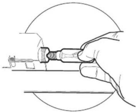
LIGHT REPLACEMENT
28W-40W light.
- Remove the metal grease filters.
- Unscrew the bulbs and replace them with new ones having the same characteristics.
- Replace the metal grease filters.
natural_image
Line drawing of a hand holding a tool, no text or symbols present| Lamp Power (W) Socket Voltage (V) Dimension (mm) ILCO$ Code | |||||
 | 28 E14 220 - 240 104 x | 35 | HSGSB/C/UB-28-220/240-E14 | ||
| (AW46) | 28 | E14 | 230 | 85x25 HDG-28-230-E14-25 | |
| (HCT) | 20 | G4 | 12 | 33 x 9 | |
 | 35 | GU10 | 230 | 51 x 50,7 | HAGS-35-230-GU10-51/40 |
| 50 | GU10 | 230 | 51 x 50,7 | HAGS-35-230-GU10-51/20 | |
 | 20 | GU4 | 12 | 40 x 35 | HRGS-20-12-GU4-35/30 |
| 20 | GU5.3 | 12 | 46 x 51 | HRGS-20-12-GU5.3-50/10 | |
| (KDD) | 16 | G13 | 95 | 720 x 26 | FD-16/40/1B-E-G13-26/720 |
| 18 | G13 | 57 | 589,8 x 26 | FD-18/40/1B-E-G13-26/600 | |
| (CD75) | 9 | G23 | 60 (lamp)220-240 (starter) | 167 x 28 | FSD-9/27/1B-I-G23 |
| 11 | G23 | 91 (lamp)220-240 (starter) | 235,8 x 28 | FSD-11/40/1B-I-G23 | |
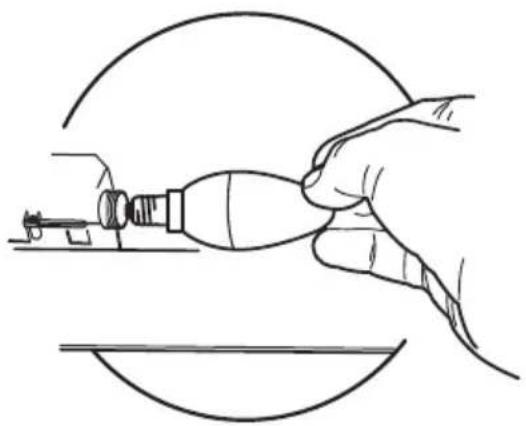
WORKTOP ILLUMINATION
If a lamp fails to function at any time, open the metal grille panel and check that the lamp is fully screwed into the holder.
When changing the lamp, an identical replacement must be fitted to ensure a safe working of the hood.
natural_image
Line drawing of a hand using a tool to adjust or install a component, no text or symbols present| Lamp Power (W) Socket | Voltage (V) Dimension (mm) ILCOS Code | ||||
| [74AW] | 4 | E14 | 220-240 | 107 x 37 | DRBB/F-4-220-240-E14-35/100 |
 | 5 | GU10 | 230 | 52 x 50 | DRPAR-5/840-220/240-GU10-35/36DRPAR-5/830-220/240-GU10-35/36 |

natural_image
Line drawing of a hand holding a tool, no text or symbols present| Ampoule | Absorption (W) | Culot Voltage | (V) Dimensions (mm) | Code ILCOS | |
| [0004] | 28 E14 220 | -240 104 x 35 | HSGSB/C/UB-28-220/240-E14 | ||
| [02YS] | 28 | E14 | 230 | 85x25 | HDG-28-230-E14-25 |
 | 20 | G4 | 12 | 33 | x 9 |
 | 35 | GU10 | 230 | 51 x 50,7 | HAGS-35-230-GU10-51/40 |
| 50 | GU10 | 230 | 51 x 50,7 | HAGS-35-230-GU10-51/20 | |
 | 20 | GU4 | 12 | 40 x 35 | HRGS-20-12-GU4-35/30 |
| 20 | GU5.3 | 12 | 46 x 51 | HRGS-20-12-GU5.3-50/10 | |
| [###] | 16 | G13 | 95 | 720 x 26 | FD-16/40/1B-E-G13-26/720 |
| 18 | G13 | 57 | 589,8 x 26 | FD-18/40/1B-E-G13-26/600 | |
| [###] | 9 | G23 | 60 (ampoule)220-240 (starter) | 167 x 28 | FSD-9/27/1B-I-G23 |
| 11 | G23 | 91 (ampoule)220-240 (starter) | 235,8 x 28 FSD- | 1/40/1B-I-G23 |
HSG/C/UB-20-
ECLAIRAGE
natural_image
Line drawing of a hand using a tool to adjust or install a component, no text or symbols present| Ampoule Absorption (W) Culot Voltage (V) Dimensions (mm) Code ILCOS | |||||
| [40WK2] | 4 | E14 | 220-240 | 107 x 37 | DRBB/F-4-220-240-E14-35/100 |
 | 5 | GU10 230 | 52 x 50 | DRPAR-5/840-220/240-GU10-35/36DRPAR-5/830-220/240-GU10-35/36 | |

natural_image
Line drawing of a hand holding a tool, no text or symbols present| Lampe Leistung (W) Fassung Spannung (V) | Größe (mm) ILCOS-Code | ||||
| (Z483) | 28 E14 220 | -240 104 x 35 | HSGSB/C/UB-28-220/240-E14 | ||
| (C8VT) | 28 | E14 | 230 | 85x25 | HDG-28-230-E14-25 |
| (W776) | 20 G4 12 33 x 9 | HSG/C/UB-20-12-G4 | |||
| (CHDZ) | 35 | GU10 | 230 | 51 x 50,7 | HAGS-35-230-GU10-51/40 |
| 50 | GU10 | 230 | 51 x 50,7 | HAGS-35-230-GU10-51/20 | |
 | 20 | GU4 | 12 | 40 x 35 | HRGS-20-12-GU4-35/30 |
| 20 GU5.3 | 12 | 46 x 51 | HRGS-20-12-GU5.3-50/10 | ||
| ---- | 16 | G13 | 95 | 720 x 26 | FD-16/40/1B-E-G13-26/720 |
| 18 | G13 | 57 | 589,8 x 26 | FD-18/40/1B-E-G13-26/600 | |
| ---- | 9 | G23 | 60 (Lampe)220-240 (Starter) | 167 x 28 | FSD-9/27/1B-I-G23 |
| 11 | G23 | 91 (Lampe)220-240 (Starter) | 235,8 x 28 | FSD-11/40/1B-I-G23 | |
BELEUCHTUNG
natural_image
Line drawing of a hand using a tool to apply material, no text or symbols presentnatural_image
Line drawing of a hand holding a tool, no text or symbols present| Lamp Stroomopname (W) Aansluiting Voltage (V) Afmeting (mm) ILCOS-code | |||||
| [602A] | 28 E14 220 | -240 104 x 35 | HSGSB/C/UB-28-220/240-E14 | ||
| [20X7] | 28 | E14 | 230 | 85x25 | HDG-28-230-E14-25 |
| [643H] | 20 G4 12 33 x 9 | HSG/C/UB-20-12-G4 | |||
 | 35 | GU10 | 230 | 51 x 50,7 | HAGS-35-230-GU10-51/40 |
| 50 | GU10 | 230 | 51 x 50,7 | HAGS-35-230-GU10-51/20 | |
 | 20 | GU4 12 | 40 x 35 | HRGS-20-12-GU4-35/30 | |
| 20 | GU5.3 | 12 | 46 x 51 | HRGS-20-12-GU5.3-50/10 | |
| ### | 16 | G13 | 95 | 720 x 26 | FD-16/40/1B-E-G13-26/720 |
| 18 | G13 | 57 | 589,8 x 26 | FD-18/40/1B-E-G13-26/600 | |
| ### | 9 | G23 | 60 (lamp)220-240 (starter) | 167 x 28 | FSD-9/27/1B-I-G23 |
| 11 | G23 | 91 (lamp)220-240 (starter) | 235,8 x 28 | FSD-11/40/1B-I-G23 | |
VERLICHTING
natural_image
Line drawing of a hand using a tool to adjust or install a mechanical component, enclosed in a circular frame (no text or symbols)| Lamp Stroomopname (W) Aansluiting Voltage (V) Afmeting (mm) ILCOS-code | |||||
| [37DS] | 4 | E14 | 220-240 | 107 x 37 | DRBB/F-4-220-240-E14-35/100 |
 | 5 | GU10 | 230 | 52 x 50 | DRPAR-5/840-220/240-GU10-35/36DRPAR-5/830-220/240-GU10-35/36 |

natural_image
Line drawing of a hand holding a tool, no text or symbols present| Lámpara | Consumo de Casquillo energía (W) | Voltaje (V) Dimensión (mm) Código ILCOS | |||
| 28 E14 2 | 35 | HSGSB/C/UB-28-220/240-E14 | |||
| 28 | E14 | 230 | HSGSB/28-230-E14-25 | ||
| 20 G4 12 | 33 x 9 HSG/C/UB-20-12-G4 | ||||
 | 35 GU10 | 230 51 x 50,7 | HAGS-35-230-GU10-51/40 | ||
| 50 GU10 | 230 51 x 50,7 | HAGS-35-230-GU10-51/20 | |||
 | 20 GU4 12 | 40 x 35 | HRGS-20-12-GU4-35/30 | ||
| 20 | GU5.3 | 12 | 46 x 51 | HRGS-20-12-GU5.3-50/10 | |
| 16 | G13 | 95 | 720 x 26 | FD-16/40/1B-E-G13-26/720 | |
| 18 | G13 | 57 589,8 x 26 | FD-18/40/1B-E-G13-26/600 | ||
| 9 | G23 | 60 (lámpara)220-240 (starter) | 167 x 28 | FSD-9/27/1B-I-G23 | |
| 11 | G23 | 91 (lámpara)220-240 (starter) | 235,8 x 28 FSD | -11/40/1B-I-G23 | |
ILUMINACION
natural_image
Line drawing of a hand using a tool to adjust or install a mechanical component, no text or symbols present| Lámpara Consumo de energía (W) Casquillo Voltaje (V) Dimensión (mm) Código ILCOS | |||||
 | 4 | E14 | 220-240 | 107 x 37 | DRBB/F-4-220-240-E14-35/100 |
 | 5 | GU10 | 230 | 52 x 50 | DRPAR-5/840-220/240-GU10-35/36DRPAR-5/830-220/240-GU10-35/36 |
natural_image
Line drawing of a hand holding a tool, no text or symbols present| Lâmpada | Absorção (W) | Ligação Tensão (V) (mm) | Código-se 60S | ||
| [84-7] | 28 E14 220 | -240 104 x 35 | HSGSB/C/UB-28-220/240-E14 | ||
| [4-607] | 28 | E14 | 230 | 85x25 | HDG-28-230-E14-25 |
| [3708] | 20 G4 12 33 x 9 HSG/C/UB-20-12-G4 | ||||
 | 35 | GU10 | 230 | 51 x 50,7 | HAGS-35-230-GU10-51/40 |
| 50 | GU10 | 230 | 51 x 50,7 | HAGS-35-230-GU10-51/20 | |
 | 20 | GU4 | 12 | 40 x 35 | HRGS-20-12-GU4-35/30 |
| 20 GU5.3 | 12 46 x 51 HRGS-20-12-GU5.3-50/10 | ||||
| [64W] | 16 | G13 | 95 | 720 x 26 | FD-16/40/1B-E-G13-26/720 |
| 18 | G13 | 57 | 589,8 x 26 | FD-18/40/1B-E-G13-26/600 | |
| [60W] | 9 | G23 | 60 (lâmpada) 220-240 (starter) | 167 x 28 | FSD-9/27/1B-I-G23 |
| 11 | G23 | 91 (lâmpada) 220-240 (starter) | 235,8 x 28 | FSD-11/40/1B-I-G23 | |
ILUMINAÇÃO
natural_image
Line drawing of a hand using a tool to adjust or install a component, no text or symbols present" Product family name for MEA market: 2726 "
natural_image
Line drawing of a hand holding a tool, no text or symbols present| ILCOS - رمر-ال | (الابعاد مم) | الفولنتاج (واط) | التوصيلة | الإستهلاك (واط) | المصباح |
| HSGSB/C/UB-28-220/240-E14 | 104 x 35 | 220 – 240 | E14 | 28 | [7042] |
| HDG-28-230-E14-25 | 85x25 | 230 | E14 | 28 |  |
| HSG/C/UB-20-12-G4 | 33 x 9 | 12 | G4 | 20 | [7XXX] |
| HAGS-35-230-GU10-51/40 | 51 x 50,7 | 230 | GU10 | 35 |  |
| HAGS-35-230-GU10-51/20 | 51 x 50,7 | 230 | GU10 | 50 | |
| HRGS-20-12-GU4-35/30 | 40 x 35 | 12 | GU4 | 20 |  |
| HRGS-20-12-GU5.3-50/10 | 46 x 51 | 12 | GU5.3 | 20 | |
| FD-16/40/1B-E-G13-26/720 | 720 x 26 | 95 | G13 | 16 | ### |
| FD-18/40/1B-E-G13-26/600 | 589,8 x 26 | 57 | G13 | 18 | |
| FSD-9/27/1B-I-G23 | 167 x 28 | 60 (مصباح)220-240 (محرف) | G23 | 9 | [642D] |
| FSD-11/40/1B-I-G23 | 235,8 x 28 | 91 (مصباح)220-240 (محرف) | G23 | 11 |
natural_image
Line drawing of a hand using a tool to adjust or install a component, no text or symbols present
- SOMMAIRE
- INHALTSVERZEICHNIS
- ILLUMINAZIONE
- GENERAL INFORMATION
- - SAFETY WARNINGS
- - INSTALLATION INSTRUCTIONS
- - Instructions for opening and removing the metal grille panel
- - Wall cabinet fixing
- - Wall mounting
- - Choice of operating mode
- - Electrical connection and working test
- - OPERATION
- - MAINTENANCE AND CLEANING
- - Grease filter
- - Cleaning Metal self-supporting Grease Filters
- - Charcoal filter
- - Worktop illumination
- - Cleaning
- Lighting
- LIGHT REPLACEMENT
- 28W-40W light.
- WORKTOP ILLUMINATION
- ECLAIRAGE
- BELEUCHTUNG
- VERLICHTING
- ILUMINACION
- ILUMINAÇÃO
Brand : Elba
Model : Classic ECH 930 WH
Category : Range hood