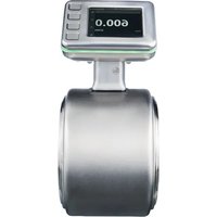
SMF720 - Flow Meter IFM - Free user manual and instructions
Find the device manual for free SMF720 IFM in PDF.


User questions about SMF720 IFM
0 question about this device. Answer the ones you know or ask your own.
Ask a new question about this device
Download the instructions for your Flow Meter in PDF format for free! Find your manual SMF720 - IFM and take your electronic device back in hand. On this page are published all the documents necessary for the use of your device. SMF720 by IFM.
USER MANUAL SMF720 IFM
Operating instructions
Magnetic-inductive flow meter
SMFx2x
Contents
1 Preliminary note.... 4
1.1 Symbols used.... 4
1.2 Warnings.... 4
2 Safety instructions 5
2.1 Cybersecurity 5
3 Transport, handling and storage 7
4 Intended use 8
4.1 Application area 8
5 Function 9
5.1 Output OUT1 selection options 10
5.2 Output OUT2 selection options 10
5.3 IO-Link 10
6 Mounting 12
6.1 Device dimensions 12
6.2 Installation position.... 12
6.3 Inlet and outlet pipe lengths.... 15
6.4 Process connection.... 15
6.4.1 Clamp adapters 17
6.4.2 Welding adapter 18
6.4.3 Screw adapter 21
6.4.4 Flange adapter.... 22
6.5 Use in hygienic areas 23
6.6 Use in hygienic areas according to 3-A.... 23
7 Electrical connection 25
8 Operating and display elements.... 27
9 Menu.... 29
9.1 Main menu 29
9.2 Submenus 30
10 Set-up 36
10.1 Guided installation via an installation wizard.... 36
11 Parameter setting 37
11.1 Parameter setting via the unit keys 37
11.2 Parameter setting via IO-Link 37
11.3 Output configuration 38
11.3.1 Analogue signal.... 38
11.3.2 Switching signal diagnostics.... 39
11.3.2.1 Switching signal for flow direction.... 40
11.3.2.2 Switching signal for fluid detection.... 40
11.3.3 Consumed quantity monitoring (totaliser function) 41
11.3.3.1 Switching signal totaliser 42
11.3.3.2 Pulse signal totaliser 43
11.3.4 Digital switching signal 44
11.3.5 Output off 46
11.4 Application configuration 47
11.4.1 Standard unit of measurement 47
11.4.2 Process value for OUT2 47
11.4.3 Error behaviour of the analogue output.... 48
11.4.4 Damping 48
11.4.5 Low flow cut-off 49
11.4.6 Output polarity 49
11.4.7 Flow direction.... 50
11.4.8 Zero calibration.... 50
11.4.9 Calibration of the measurement characteristic.... 51
11.4.10 Influence of the medium on the temperature.... 52
11.4.11 Date and Time 53
11.4.12 Energy-saving mode 53
11.4.13 Totaliser reset 54
11.4.14 Counting method of the totalisers 55
11.4.15 Reset the device 56
11.5 Display settings 57
11.5.1 Display language.... 57
11.5.2 Display rotation 58
11.5.3 Display brightness.... 58
11.5.4 Display update rate 58
11.5.5 Display layout.... 59
11.5.6 Display colour setting.... 60
11.6 Diagnostics 61
11.6.1 Read totaliser values 61
11.6.2 Memory 62
11.6.3 Operating hours counter 62
11.6.4 Internal temperature.... 62
11.6.5 Operating status LED 63
11.6.6 Event history 63
11.7 Service functions.... 64
11.7.1 Device information 64
11.7.2 Configuration 64
11.7.3 Simulation 65
11.7.4 Documents 65
11.7.5 Binary data transmission (BLOB).... 66
11.7.6 Optical localisation 66
11.7.7 Lock/unlock 67
11.7.8 Guided installation (wizard) 67
12 Operation.... 68
13 Troubleshooting.... 69
13.1 Warning messages.... 69
13.2 Error messages.... 70
14 Maintenance, repair and disposal 71
14.1 Maintenance 71
14.2 Replacing the electronic unit 71
14.3 Disposal 75
15 Factory settings.... 76
1 Preliminary note
You will find instructions, technical data, approvals and further information using the QR code on the unit / packaging or at documentation.ifm.com.
1.1 Symbols used
√ Requirement
Instruction
Reaction, result
bold Designation of keys, buttons or indications
→ Cross-reference without link
→ Cross-reference with link

Important note
Non-compliance may result in malfunction or interference

Information
Supplementary note
1.2 Warnings
Warnings indicate the possibility of personal injury and damage to property. This enables safe product handling. Warnings are graded as follows:

WARNING
Warning of serious personal injury
▷ If the warning is not observed, fatal and serious injuries are possible.

CAUTION
Warning of minor to moderate personal injury
▷ If the warning is not observed, minor to moderate injuries are possible.

ATTENTION
Warning of damage to property
▷ If the warning is not observed, damage to property is possible.
2 Safety instructions
- The unit described is a subcomponent for integration into a system.
- The system architect is responsible for the safety of the system.
-
The system architect undertakes to perform a risk assessment and to create documentation in accordance with legal and normative requirements to be provided to the operator and user of the system. This documentation must contain all necessary information and safety instructions for the operator, the user and, if applicable, for any service personnel authorised by the architect of the system.
-
Read this document before setting up the product and keep it during the entire service life.
- The product must be suitable for the corresponding applications and environmental conditions without any restrictions.
- Only use the product for its intended purpose (→ Intended use).
- Only use the product for permissible media.
- If the operating instructions or the technical data are not adhered to, personal injury and/or damage to property may occur.
- The manufacturer assumes no liability or warranty for any consequences caused by tampering with the product or incorrect use by the operator.
- Installation, electrical connection, set-up, operation and maintenance of the product must be carried out by qualified personnel authorised by the machine operator.
- Protect units and cables against damage.

ATTENTION
Applications where steam is applied
▷ Risk of mechanical damage of the sensor or the piping system due to steam surge.
▶ Protect the sensor from excessive stress due to cavitation and steam surge.
▶ Design the piping system according to the state of the art.
▶ Do not install the sensor in the direct vicinity of fittings, pipe bends and the like in order to prevent unnecessary maximisation of steam surges.
▶ Preheat the system before the steam enters and remove liquid residues from the pipes, for example by blowing out or other suitable measures.
▷ The permissible temperatures of the sensor must not be exceeded ➕ Data sheet.

ATTENTION
Direct UV radiation
▷ The display may become cloudy or yellow.
▶ Ensure that the display is not exposed to direct sunlight.
▶ If this cannot be avoided, use a protective cap. This can be ordered as an accessory at www.ifm.com.
2.1 Cybersecurity
Installation
The device is suitable for operation in a secure environment according to IEC 62443-1-1.
The device was designed for operation behind a firewall.
▶ Carry out a risk assessment of the system according to IEC 62443-1-1.
▶ Take measures to ensure physical security.
Operation
▶ Observe the security functions described in the product documentation and the recommendations for their use.
Maintenance
- ▶ Back up system configuration and system data in accordance with your company’s change management processes.
Decommissioning
▶ Ensure that no sensitive information can fall into unauthorised hands.
▶ Always reset the system settings to the factory settings before decommissioning the device.
3 Transport, handling and storage
▶ Store the device in its original packaging.
▶ When the device is to be stored again, use the original packaging.
▶ Otherwise, provide unused connections with either a mating connector or a protective cap and pack the device in suitable packaging.
▶ Observe the permissible ambient conditions for the device during storage (→ Technical data).

CAUTION
Transport of heavy devices.
▷ Personal injury or damage to devices is possible if heavy devices fall during transport.
▶ Transport the device to the assembly site in its original packaging.
▶ After unpackaging the device but leaving the protective caps in place, transport it using suitable tools (e.g. carrying straps).
4 Intended use
The unit monitors liquid media.
The device measures the flow velocity, the volume flow (consumed quantity / time), the consumed quantity, the medium temperature and the conductivity.
4.1 Application area
Use in hygienic areas for liquid media with a conductivity of ≥ 5 µS/cm .

This is a class A product. This product may cause radio interference in domestic areas.
▶ If required, take appropriate EMC screening measures.

Pressure Equipment Directive (PED): The units comply with the Pressure Equipment Directive and are designed and manufactured for group 2 fluids in accordance with the sound engineering practice. Use of media from group 1 fluids on request.
5 Function
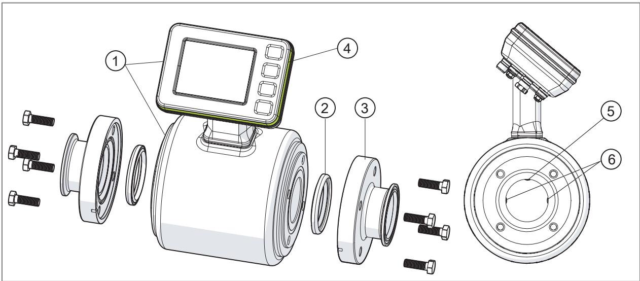
Fig. 1: Product description
1: SMFxxx device (measuring circuit and display)
2: Exxxxx seal, can be ordered separately from www.ifm.com
3: Exxxxx process adapter, can be ordered separately from www.ifm.com
4: Operating status LED (LED ring)
5: Temperature-measuring electrode in the measuring pipe
6: Flow-measuring electrodes in the measuring pipe
Operating principle:
- The device detects the volumetric flow on the magnetic-inductive volumetric flow measuring principle.
- As additional process values the device measures the temperature of the medium.
- The unit displays the current process values.
- The unit can be operated in SIO mode (standard input-output) or in IO-Link mode.
- The device indicates all self-diagnostic options through the colour signals of an operating status LED.
-
A simulation mode and guided installation via a wizard enable simplified set-up of the sensor.
• The device has the following output functions: -
Analogue signal ➞ 38:
flow, temperature, conductivity - Consumed quantity monitoring (totaliser function) ➞ 41:
switching signal or pulse signal - Switching signal diagnostics ➕ 39:
Flow direction, fluid detection - Digital switching signal → 44:
limit value monitoring of flow, temperature, conductivity, totaliser
- The device provides the following options for application configuration:
- Standard unit of measurement → 47, Error behaviour of the analogue output → 48, Damping → 48, Low flow cut-off → 49, Output polarity → 49, Flow direction → 50, Zero calibration → 50, Calibration of the measurement characteristic → 51, Influence of the medium on the temperature → 52, Energy-saving mode → 53, Totaliser reset → 54, Counting method of the totalisers → 55.
• In addition, the device provides other diagnostic and service functions:
- Read totaliser values ➞ 61
- Memory ➞ 62
- Operating hours counter → 62
- Internal temperature → 62
- Operating status LED ➕ 63
- Event history ➞ 63
- Device information ➞ 64
- Simulation ➞ 65
- Configuration → 64
- Documents ➕ 65
- Binary data transmission (BLOB) → 66
- Optical localisation ➞ 66
- Lock / unlock ➕ 67
- Reset the device ➞ 56
- Display settings ➞ 57
5.1 Output OUT1 selection options
- Pulse signal totaliser
- Switching signal totaliser
- Switching signal diagnosis
– Direction of flow -
Fluid detection
-
IO-Link
• OFF (output switched to high impedance)
5.2 Output OUT2 selection options
- Pulse signal totaliser
- Switching signal totaliser
- Analogue signal flow
• Analogue signal temperature
• Analogue signal for conductivity - Switching signal diagnosis
– Direction of flow
- Fluid detection
• Input for external totaliser reset
• OFF (output switched to high impedance)
5.3 IO-Link
IO-Link is a communication system for connecting intelligent sensors and actuators to automation systems. IO-Link is standardised in the IEC 61131-9 standard.

General information on IO-Link at io-link.ifm

Input Output Device Description (IODD) with all parameters, process data and detailed descriptions of the device at documentation.ifm.com
IO-Link offers the following advantages:
• Interference-free transmission of all data and process values
• Parameter setting in the running process or presetting outside the application
- Parameters for identifying the connected devices in the system
• Additional parameters and diagnostic functions
• Automatic backup and restore of parameter sets in case of device replacement (data storage)
- Logging of parameter sets, process values and events
• Device description file (IODD - Input Output Device Description) for easy project planning
• Standardised electrical connection
- Remote maintenance
6 Mounting

CAUTION
If the medium temperature is above 50\ °C ( 122\ °F ), parts of the housing can increase in temperature to over 65\ °C ( 149\ °F ).
▷ Risk of burns.
▶ Protect the housing against contact with flammable substances and unintentional contact.
▶ Apply the supplied warning label to the sensor cable.

ATTENTION
No functional earthing when installed in an ungrounded pipe system (e.g. plastic pipes).
▷ Reduction in measurement accuracy or damage to the device.
▶ Attach the grounding cable to the ground connection and establish an equalisation of potential between the medium and the device (→ Electrical connection).
▶ Make sure that no pressure is applied to the system.
▶ Ensure that no media can leak at the mounting location during installation.
▶ Avoid deposits, accumulated gas and air in the pipe system.

After installation, air bubbles in the system can affect the measurement.
▶ Rinse the system after installation for ventilation.
6.1 Device dimensions


| DN[mm] | L[mm] | G[mm] | H[mm] | diA[mm] |
| 15 | 86 | 241.4 | 114.3 | 16 |
| 25 | 86 | 241.4 | 114.3 | 26 |
| 40 | 140 | 252.6 | 125 | 34.3 |
| 50 | 140 | 267.5 | 139.7 | 47 |
| 65 | 140 | 281.6 | 154 | 59.7 |
| 80 | 140 | 295.9 | 168.3 | 72.4 |
| 100 | 140 | 319.6 | 192 | 96.9 |
| 125 | 200 | 346.7 | 219.1 | 119.5 |
| 150 | 200 | 381.6 | 254 | 146.4 |
Fig. 2: Dimensions of the sensors depending on the design (nominal width DN)
6.2 Installation position
▶ Install the unit so that the measuring pipe is always completely filled.
▶ Install in front of or in a rising pipe.

Fig. 3: Orientation of the flow-measuring electrodes

When installed in a vertical position, the electrodes for flow measurement (1) should be in the same plane. Any deviation from this can lead to measurement inaccuracies.
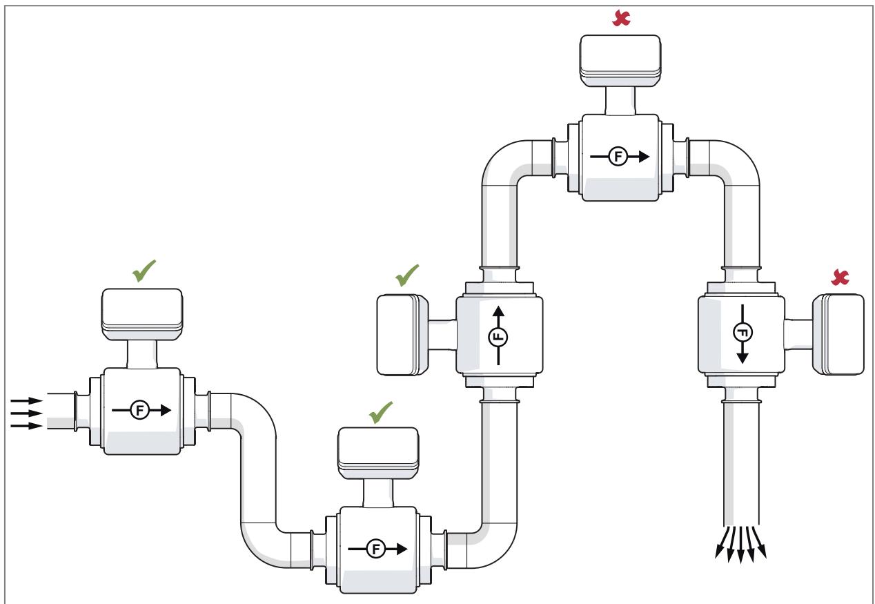
Fig. 4: Recommended and non-recommended installation positions

Flow direction ➕ 50

The unit can be installed independently of the orientation if the following is ensured:
- No air bubbles can form in the pipe system.
- The pipes are always completely filled.

In case of horizontal installation: as a result of design requirements a small quantity of the medium always remains in the measuring channel after switching off the pump.
▶ Ensure that no medium remains in the measuring channel.
Avoid the following installation positions:
- At the highest point of the pipe system.
- Directly upstream of a free pipe spout in a downpipe
• On the suction side of a pump.
Installation in the vicinity of control valves:
▶ Install the device upstream of the control valve in the direction of flow:
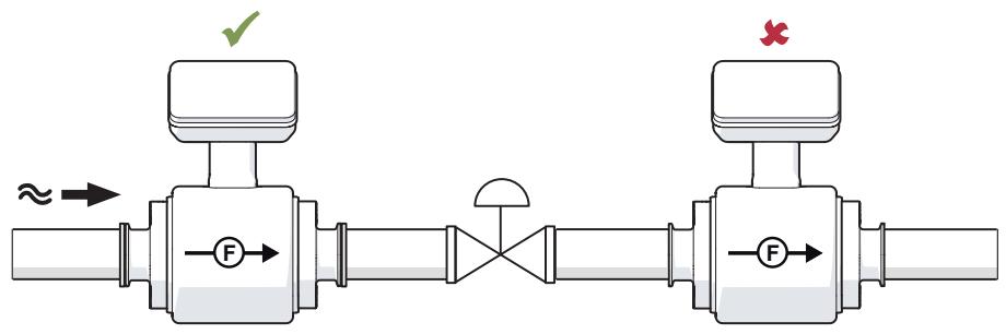
Installation in the vicinity of pumps:
▶ Install the device downstream of the pump in the direction of flow to avoid negative pressure in the measuring pipe:
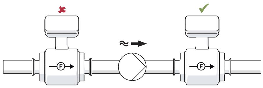

When installed upstream of a pump, cavitation may occur if the pump is under low pressure or high vacuum conditions.
▷ This can lead to the sensor being damaged.

When using piston pumps, piston diaphragm pumps or peristaltic pumps:
▶ Install pulsation damper.
Installation with very strong vibrations:
▶ Support and secure the device and the pipe:


6.3 Inlet and outlet pipe lengths
Structures in the pipe, bends, valves, reducing pieces and the like affect the function of the unit.
▶ Adhere to the distances between sensor and interference.

Shut-off valves and control devices are not allowed directly in front of the unit.
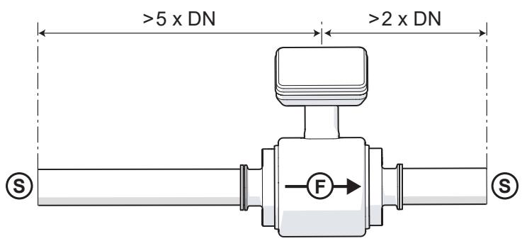
Fig. 5: Inlet and outlet pipe lengths
DN: Nominal width of the sensor
S: Interference
6.4 Process connection
Using process adapters the unit can be adapted to different process connections.
ifm offers hygienic process adapters and seals made of the materials FKM, EPDM and VMQ, which must be ordered separately as accessories.

Information about available accessories at documentation.ifm.com.

▶ Adhere to the installation instructions for use in hygienic areas.

ATTENTION
Sensitive sealing areas on the flange of the process adapters.
▷ The PFA material on the flange can be easily damaged after removing the protective caps, which can lead to leaks in the process connection.
▶ Carefully remove the protective caps.
▶ Avoid any impact on or scratching of the PFA sealing area.

Fig. 6: Installation of the device in the process
1: Process adapters
2: Seal
3: Protective cap
4: Sensor
How to proceed:

The sensor, the process adapters and the seals must be ordered separately.

Additional instructions for the respective process adapters are described in the following chapters.
▶ Remove the seal that fixes the protective caps to the sensor.

No replacement is possible after the product seal has been removed.
▶ Carefully remove the protective caps from the sensor.
▶ Insert the seals carefully into the grooves of the process adapters. Ensure that the seals are clean, undamaged and correctly centered.
▶ Fasten the process adapters to the device hand-tight using the enclosed screws.
▶ Tighten the screw heads evenly in three steps and observe the maximum tightening torque:
- Step 1 approx. 50% of the specified maximum tightening torque.
- Step 2: approx. 80% of the specified maximum tightening torque.
- Step 3: 100% of the specified maximum tightening torque.
| Nominal width | Pressure rating | Screws | Maximum tightening torque |
| DN 15 | PN 40 | 4 x M6x18 | 6.5 Nm |
| DN 25 | PN 40 | 4 x M6x18 | 6.5 Nm |
| DN 40 | PN 40 | 4 x M8x25 | 16 Nm |
| DN 50 | PN 25 | 4 x M8x25 | 16 Nm |
| DN 65 | PN 25 | 6 x M8x25 | 16 Nm |
| DN 80 | PN 25 | 6 x M8x25 | 16 Nm |
| DN 100 | PN 25 | 6 x M8x25 | 16 Nm |
| DN 125 | PN 10 | 6 x M10x35 | 32.5 Nm |
| DN 150 | PN 10 | 6 x M10x35 | 32.5 Nm |
Tab. 1: Maximum tightening torque
▶ Connect the device with the mounted process adapters to the pipe on both sides in the marked direction of flow.
6.4.1 Clamp adapters
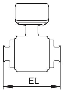

Fig. 7: Installation with clamp adapter
EL: Installation depth of sensor + adapter
∅ A: Outer diameter of the adapter
∅ B: Inner diameter of the adapter
ifm electronic offers clamp adapters in compliance with ISO 2852, DIN 32676-A (DIN) and DIN 32676-C (ASME BPE) for various pipe standards:
| Type | Nominal width | ifm adapter E4048x | Dimensions in mm ➕ Figure above | Applicable pipe standard | ||||||
| ISO 2852 | EL | ∅ B | ∅ A | ISO 2037 | DIN EN 10357 series D | BS 4825 part 1 | DIN EN 10357 series C | JIS G3447 | ||
| SMF1xx | DN15 | × | ||||||||
| SMF2xx | DN25 | √ | 175 | 23 | 50.4 | √ | √ | × | × | × |
| SMF3xx | DN40 | √ | 220 | 36 | 50.5 | √ | √ | × | × | √ |
| SMF4xx | DN50 | √ | 220 | 49 | 64 | √ | √ | × | × | × |
| SMF5xx | DN65 | √ | 220 | 60 | 77.5 | √ | √ | √ | √ | × |
| SMF6xx | DN80 | √ | 220 | 73 | 91 | √ | √ | × | √ | × |
| SMF7xx | DN100 | √ | 220 | 98 | 119 | √ | √ | √ | × | √ |
| SMF8xx | DN125 | √ | 300 | 136 | 155 | √ | × | √ | × | × |
| SMF9xx | DN150 | √ | 300 | 163 | 183 | √ | × | √ | × | × |
Tab. 2: Clamp ISO 2852
| Type | Nominal width | ifm adapter E4049x | Dimensions in mm ➔ Figure above | Applicable pipe standard | |||||
| DIN 32676-A (DIN) | EL | ∅ B | ∅ A | DIN EN 10357 series A | DIN 11850 series 2 | DIN 11850 series 1 | DIN 11866 series A | ||
| SMF1xx | DN15 | √ | 168 | 16.1 | 33.9 | √ | √ | √ | √ |
| SMF2xx | DN25 | √ | 175 | 26.1 | 50.4 | √ | √ | √ | √ |
| SMF3xx | DN40 | √ | 220 | 38.1 | 50.5 | √ | √ | √ | √ |
| SMF4xx | DN50 | √ | 220 | 50.1 | 64 | √ | √ | √ | √ |
| SMF5xx | DN65 | √ | 220 | 66.1 | 91 | √ | √ | × | √ |
| SMF6xx | DN80 | √ | 220 | 81.1 | 106 | √ | √ | × | √ |
| SMF7xx | DN100 | √ | 220 | 100.1 | 119 | √ | √ | × | √ |
| SMF8xx | DN125 | √ | 300 | 125 | 155 | √ | √ | × | √ |
| SMF9xx | DN150 | √ | 300 | 150 | 183 | √ | √ | × | √ |
Tab. 3: Clamp DIN 32676-A (DIN)
| Type | Nominal width | ifm adapter E4061x | Dimensions in mm ➕ Figure above | Applicable pipe standard | ||||||
| DIN 32676-C (ASME BPE) | EL | ∅ B | ∅ A | DIN EN 10357 series C | DIN 11866 series C | BS 4825 part 1 | ISO 2037 | DIN EN 10357 series D | ||
| SMF1xx | DN15 | √ | 168 | 9.5 | 25.1 | √ | √ | × | × | × |
| SMF2xx | DN25 | √ | 175 | 22.2 | 50.4 | √ | √ | √ | × | × |
| SMF3xx | DN40 | √ | 220 | 35 | 50.5 | √ | √ | √ | √ | × |
| SMF4xx | DN50 | √ | 220 | 48 | 64 | √ | √ | √ | × | × |
| SMF5xx | DN65 | √ | 220 | 60 | 77.5 | √ | √ | √ | √ | √ |
| SMF6xx | DN80 | √ | 220 | 73 | 91 | √ | √ | √ | √ | √ |
| SMF7xx | DN100 | √ | 220 | 97 | 119 | √ | √ | √ | √ | √ |
| SMF8xx | DN125 | × | ||||||||
| SMF9xx | DN150 | √ | 300 | 146.96 | 167 | √ | √ | × | × | × |
Tab. 4: DIN 32676-C (ASME BPE)
6.4.2 Welding adapter
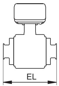
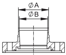
Fig. 8: Installation with welding adapter
EL: Installation depth of sensor + adapter
∅ A: Outer diameter of the adapter
∅ B: Inner diameter of the adapter
ifm electronic offers welding adapters in compliance with EN 10357 series A (DIN), C (ASME BPE) and D (SMS) for various pipe standards:
| Type | Nominal width | ifm adapter E4047x | Dimensions in mm ➔ Figure above | Applicable pipe standard | |||||
| EN 10357 series A (DIN) | EL | ∅ A | ∅ B | DIN EN 10357 series A | DIN 11850 series 2 | DIN 11866 series A | DIN 11850 series 1 | ||
| SMF1xx | DN15 | √ | 132.6 | 19 | 16 | √ | √ | √ | √ |
| SMF2xx | DN25 | √ | 132.6 | 29 | 26 | √ | √ | √ | √ |
| SMF3xx | DN40 | √ | 220 | 41 | 38 | √ | √ | √ | √ |
| SMF4xx | DN50 | √ | 220 | 53 | 50 | √ | √ | √ | √ |
| SMF5xx | DN65 | √ | 220 | 70 | 66 | √ | √ | √ | × |
| SMF6xx | DN80 | √ | 220 | 85 | 81 | √ | √ | √ | × |
| SMF7xx | DN100 | √ | 220 | 104 | 100 | √ | √ | √ | × |
| SMF8xx | DN125 | √ | 300 | 129 | 125 | √ | √ | √ | × |
| SMF9xx | DN150 | √ | 300 | 154 | 150 | √ | √ | √ | × |
Tab. 5: Welding adapter EN 10357 series A (DIN)
| Type | Nominal width | ifm adapter E4062x | Dimensions in mm ➕ Figure above | Applicable pipe standard | ||||||
| EN 10357 series C (ASME BPE) | EL | ∅ A | ∅ B | DIN EN 10357 series C | DIN 11866 series C | BS 4825 part 1 | ISO 2037 | DIN EN 10357 series D | ||
| SMF1xx | DN15 | √ | 132.6 | 12.7 | 9.4 | √ | √ | × | × | × |
| SMF2xx | DN25 | √ | 132.6 | 25.4 | 22.1 | √ | √ | √ | × | × |
| SMF3xx | DN40 | √ | 220 | 38 | 35 | √ | √ | √ | √ | × |
| SMF4xx | DN50 | √ | 220 | 51 | 48 | √ | √ | √ | × | × |
| SMF5xx | DN65 | √ | 220 | 64 | 60 | √ | √ | √ | √ | √ |
| SMF6xx | DN80 | √ | 220 | 76 | 73 | √ | √ | √ | √ | √ |
| SMF7xx | DN100 | √ | 220 | 102 | 97 | √ | √ | √ | √ | √ |
| SMF8xx | DN125 | × | ||||||||
| SMF9xx | DN150 | √ | 300 | 152 | 147 | √ | √ | × | × | × |
Tab. 6: Welding adapter EN 10357 series C (ASME BPE)
| Type | Nominal width | ifm adapter E4063x | Dimensions in mm ➕ Figure above | Applicable pipe standard | |||||
| EN10357 series D (SMS) | EL | ∅ A | ∅ B | ISO 2037 | DIN EN 10357 series D | BS 4825 part 1 | JIS G3447 | ||
| SMF1xx | DN15 | × | |||||||
| SMF2xx | DN25 | √ | 132.6 | 25 | 22.6 | √ | √ | × | × |
| SMF3xx | DN40 | √ | 220 | 38 | 36 | √ | √ | × | √ |
| SMF4xx | DN50 | √ | 220 | 51 | 49 | √ | √ | × | × |
| SMF5xx | DN65 | * | |||||||
| SMF6xx | DN80 | * | |||||||
| SMF7xx | DN100 | √ | 220 | 102 | 98 | √ | √ | √ | √ |
| SMF8xx | DN125 | × | |||||||
| SMF9xx | DN150 | × | |||||||
Tab. 7: Welding adapter EN 10357 series D (SMS)
* design identical to welding adapter EN 10357 series C
How to proceed:

ATTENTION
Welding work
▷ Destruction of the measuring electronics due to improper welding.
▶ The welding must only be carried out by qualified personnel according to the state of the art.
▶ Prepare the pipe ends carefully. The surfaces must be free from any contamination.
▶ The welding materials must be suitable for the adapter and pipe materials.
▶ The weld seams should be executed in such a way that the pipe and adapter do not warp during welding.
▶ Only install the device after the welding and subsequent cooling phase.
▶ Do not ground the welding system via the device.
▶ Carefully remove the protective caps from the sensor.
▶ Fasten the process adapters to the device hand-tight using the enclosed screws.
▶ Insert the device with the pre-mounted process adapters into the pipe and weld the adapters to the pipe with sufficient adhesive force using several welding spots.
▶ Disconnect the device from the process adapters by loosening the screws and carefully remove the device.
▶ Carefully replace the protective caps on the two sensor connections.
▶ Now weld the two process adapters firmly to the pipe.
▶ Ensure sufficient intervals between the individual welding operations to avoid glowing through or warping of the adapter due to overheating.
▶ Let the adapters and the pipe cool down.
▶ Clean welding residue from the adapters, pipe and weld seams.
▶ Carefully remove the protective caps from the sensor.
▶ Insert the seals carefully into the grooves of the process adapters. Ensure that the seals are clean, undamaged and correctly centered.
▶ Position the device in the marked flow direction between the two process adapters.
▶ Fasten the process adapters to the device hand-tight using the enclosed screws.
▶ Tighten the screw heads in three steps with the maximum tightening torque ➞ 16.
6.4.3 Screw adapter


Fig. 9: Installation with screw adapter
EL: Installation depth of sensor + adapter
∅ A: Outer diameter of the adapter
∅ B: Inner diameter of the adapter
ifm electronic offers screw adapters in compliance with DIN 11851 (pipe fitting) and SMS 1145 for various pipe standards:
| Type | Nominal width | ifm adapter E4050x | Dimensions in mm ➕ Figure above | Applicable pipe standard | |||||
| DIN 11851 | EL | ∅ B | ∅ A | DIN EN 10357 series A | DIN 11850 series 2 | DIN 11850 series 1 | DIN 11866 series A | ||
| SMF1xx | DN15 | √ | 174 | 16.1 | Rd 34 x 1/8 | √ | √ | √ | √ |
| SMF2xx | DN25 | √ | 190 | 26.1 | Rd 52 x 1/6 | √ | √ | √ | √ |
| SMF3xx | DN40 | √ | 260 | 38 | Rd 65 x 1/6 | √ | √ | √ | √ |
| SMF4xx | DN50 | √ | 260 | 50 | Rd 78 x 1/6 | √ | √ | √ | √ |
| SMF5xx | DN65 | √ | 270 | 66 | Rd 95 x 1/6 | √ | √ | × | √ |
| SMF6xx | DN80 | √ | 280 | 81 | Rd 110 x 1/4 | √ | √ | × | √ |
| SMF7xx | DN100 | √ | 290 | 100 | Rd 130 x 1/4 | √ | √ | × | √ |
| SMF8xx | DN125 | √ | 380 | 125 | Rd 160 x 1/4 | √ | √ | × | √ |
| SMF9xx | DN150 | √ | 390 | 150 | Rd 190 x 1/4 | √ | √ | × | √ |
Tab. 8: Screw connection DIN 11851 (pipe fitting)
| Type | Nominal width | ifm adapter E4051x | Dimensions in mm ➕ Figure above | Applicable pipe standard | ||||||
| SMS 1145 | EL | ∅ B | ∅ A | ISO 2037 | DIN EN 10357 series D | BS 4825 part 1 | DIN EN 10357 series C | JIS G3447 | ||
| SMF1xx | DN15 | × | ||||||||
| SMF2xx | DN25 | √ | 148 | 22.6 | Rd 40 x 1/6 | √ | √ | × | × | × |
| SMF3xx | DN40 | √ | 256 | 35.6 | Rd 60 x 1/6 | √ | √ | × | × | √ |
| SMF4xx | DN50 | √ | 256 | 48.6 | Rd 70 x 1/6 | √ | √ | × | × | × |
| SMF5xx | DN65 | √ | 266 | 60.3 | Rd 85 x 1/6 | √ | √ | √ | √ | × |
| SMF6xx | DN80 | √ | 276 | 72.9 | Rd 98 x 1/6 | √ | √ | × | √ | × |
| SMF7xx | DN100 | √ | 286 | 97.6 | Rd 132 x 1/6 | √ | √ | √ | × | √ |
| SMF8xx | DN125 | × | ||||||||
| SMF9xx | DN150 | × | ||||||||
Tab. 9: Screw connection SMS 1145
6.4.4 Flange adapter


Fig. 10: Installation with flange adapter
EL: Installation depth of sensor + adapter
∅ A: Outer diameter of the adapter
∅ B: Inner diameter of the adapter
ifm electronic offers aseptic flange adapters in compliance with DIN 11864-2A:
| Type | Nominal width | ifm adapter E4052x | Dimensions in mm ➔ Figure above | Applicable pipe standard | |||||
| DIN 11864-2A | EL | ∅ B | ∅ A | DIN EN 10357 series A | DIN 11850 series 2 | DIN 11850 series 1 | DIN 11866 series A | ||
| SMF1xx | DN15 | √ | 183 | 16 | 59 | √ | √ | √ | √ |
| SMF2xx | DN25 | √ | 183 | 26 | 70 | √ | √ | √ | √ |
| SMF3xx | DN40 | √ | 246 | 38 | 82 | √ | √ | √ | √ |
| SMF4xx | DN50 | √ | 246 | 50 | 94 | √ | √ | √ | √ |
| SMF5xx | DN65 | √ | 246 | 66 | 113 | √ | √ | × | √ |
| SMF6xx | DN80 | √ | 270 | 81 | 133 | √ | √ | × | √ |
| SMF7xx | DN100 | √ | 278 | 100 | 159 | √ | √ | × | √ |
| SMF8xx | DN125 | √ | 362 | 125 | 183 | √ | √ | × | √ |
| SMF9xx | DN150 | √ | 362 | 150 | 213 | √ | √ | × | √ |
Tab. 10: Aseptic flange adapter DIN 11864-2A
6.5 Use in hygienic areas

The sensor is suited for CIP (cleaning in process) and SIP (sterilisation in place) when installed correctly.
▶ Observe the application limits (temperature and material resistance) according to the data sheet.
▶ Install the device so that there is a minimum gradient in the measuring channel and no medium remains in the pipe after switching off the pump.
▶ Use self-draining installation.
▶ Align the leakage ports of the process adapters so that they are clearly visible and point downwards.
6.6 Use in hygienic areas according to 3-A
▶ Ensure that the installation of the device in the system complies with 3-A guidelines.
▶ Use only process adapters and seals with 3-A certification and marked with the 3-A symbol (→ Accessories at www.ifm.com).

▶ For use according to 3-A, take note of the corresponding regulations for cleaning and maintenance.
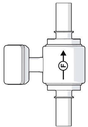

Fig. 11: Process connection according to 3-A
1: Minimum gradient
▶ To allow the medium to flow out of the process adapter, mount the device in the following installation position:
• Vertical installation in a rising pipe ➞ 12.
- or -
• Horizontal position with a slight gradient so that the medium does not come to a standstill:
| DN | DIN3267 6-A | DIN3267 6-C | ISO 2852 | EN10357 -A | EN10357 -C | EN10357 -D | DIN1186 4-2A | DIN1185 1 | SMS 114 5 |
| DN 15 | 3° | 17° | × | 3° | * | × | 3° | 3° | × |
| DN 25 | 3° | 10° | 6° | 3° | * | * | 3° | 3° | 9° |
| DN 40 | 6° | 3° | 4° | 6° | 3° | 4° | 6° | 6° | 4° |
| DN 50 | 6° | 3° | 4° | 6° | 3° | 4° | 6° | 6° | 4° |
| DN 65 | 10° | 3° | 3° | 10° | 3° | × | 7° | 7° | 3° |
| DN 80 | 13° | 3° | 3° | 13° | 3° | × | 8° | 8° | 3° |
| DN 100 | 6° | 3° | 3° | 6° | 3° | 3° | 6° | 6° | 3° |
| DN 125 | 7° | × | 16° | 7° | × | × | 5° | 5° | × |
| DN 150 | 5° | 3° | 16° | 5° | 3° | × | 4° | 4° | × |
Tab. 11: Minimum gradient for drainage capacity
* installation in rising pipe recommended; × adapter not available
▶ Regularly check the seals between the device and the process adapter for deposits and damage.
▶ In case of soiling, clean the seals with a suitable cleaning liquid (e.g. alcoholic solution).
▶ Replace the seals if necessary.

The frequency of the seal replacement depends on the frequency of the cleaning cycles, the media temperature and the cleaning temperature.
▶ Define regular cleaning cycles according to the process requirements.
7 Electrical connection
The device has two M12 connectors:
- The operating connector is for the operation of the device.
- The service connector must only be used by ifm staff when the device is being serviced.
▶ Cover the connectors with protective caps when they are not in use. Protective caps can be ordered individually from documentation.ifm.com.

Fig. 12: Connectors
1: Operating connectors (see wiring diagram)
2: Service connector (only for service personnel; on delivery: with protective cap)
3: Ventilation diaphragm (ensures reliable pressure compensation in the housing to prevent moisture build-up inside the housing. The ventilation diaphragm is protected against damage by a screwed filter cover with circumferential ports.)
4: Ground connection. Grounding clamps for M12 connectors can be ordered at www.ifm.com.

The unit must be connected by a qualified electrician.
Observe the national and international regulations for the installation of electrical equipment. Voltage supply according to SELV, PELV.
The input and output circuits are insulated from each other and from device surfaces that could be touched with basic insulation according to IEC 61010-1 (secondary circuit with max. 32 V DC, supplied from the mains circuit up to 300 V of overvoltage category II).
The external wiring has to be carried out in a way that ensures the required separation from other circuits.
▶ Disconnect power.
▶ Connect the unit as follows:


Fig. 13: Wiring diagram; MP: multifunction (IN, OUT, Data)
| Pin | Assignment |
| 1 | L+ |
| 3 | L- |
| 4 (MP1) | Pulse signal totaliser Switching signal totaliser Switching signal diagnosisIO-LinkOFF (output switched to high impedance) |
| 2 (MP2) | Pulse signal totaliser Switching signal totaliser Analogue signal flow Analogue signal temperature Analogue signal for conductivity Switching signal diagnosis Input for external totaliser resetOFF (output switched to high impedance) |
Circuit examples:


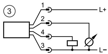

1: 2 x positive switching
3: 1 x positive switching / 1 x analogue
2: 2 x negative switching
4: 1 x negative switching / 1 x analogue

ifm offers a connection set with article number ZZ8903 which makes it easy to replace a conventionally wired flow meter with an SMF sensor using the existing electrical connections ("Retrofit").
→ Accessories at ifm.com.
8 Operating and display elements

Fig. 14: Operating and display elements
1: TFT-Display 3.5": Shows 1 to 4 process values ➞ 59.
2: Title line: Describes the status of the device (normal operation, warning messages, error messages).
3: Operating status LED (LED ring): Changes colour to signal the status of the device. ➕ 63
4: Device keys: Keys for changing views and setting parameters ➞ 37.
5: Key symbols: Indicate the functions of the corresponding device keys on the display. The key symbols may be different on the process value display and in the individual menus.

If the device measures a high internal temperature, the display brightness is automatically adjusted:
Internal temperature > 75 °C: brightness is reduced to 25%.
Internal temperature ≥ 90 ° C: display is automatically switched off.
Switching between display screens:
The device keys can be used to switch between different process value displays during operation:
▶ Press ◎ or ◀.
▷ The display shows the various display options.
▶ Press ▶ or ◀ until the desired display screen is highlighted.
▶ Press Ⓞ.
▷ The display shows all of the available information about the selected display screen.
▶ Press ⬇ or Ⓔ to scroll through the selected display screen.
▷ After 30 s, the device returns to the standard display.

Fig. 15: Switching between display screens
1: Standard display according to the set display layout ➕ 59.
2: Fourfold display:
4 process values or 3 process values and arrow for flow direction ➕ 50.
3: Detailed view of the selected process value

The maximum resolution of the process value display is up to 3 decimal places. The unit in which the totaliser is displayed depends on the parameter settings of the uni. F parameter.
9 Menu
The figures in which the menus are displayed show the parameters that can be set on the unit by key input. These parameters and other functions are also available via the IO-Link interface.

The designation of the parameters in the parameter setting software may differ from the designations in the device display.
9.1 Main menu
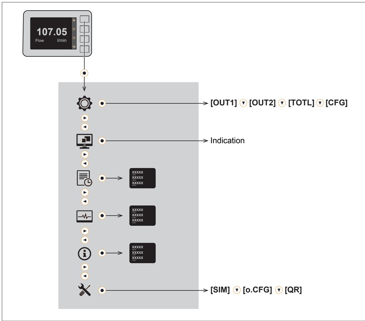
| Symbol | Name | Explanation | |
 | Settings | Switch to the following submenus ➕ 30: OUT1: output 1, OUT2: output 2, TOTL: totaliser, CFG: configuration. | |
 | Indication | Switch to the display menu. | |
 | Event history | Shows previous events ➕ 63. | |
 | Diagnostics | Shows diagnostics information ➕ 61: minimum and maximum flow, operating hours, internal temperature. | |
 | Device info | Shows device-specific information ➕ 64. | |
| Symbol | Name | Explanation |
| Service | Transition to the following submenus and display screens:• SIM: Simulation ➕ 35. • o. CFG: Configuration ➕ 64. • QR: Shows the QR codes with links to the data sheet, the operating instructions and the certificate at www.ifm.com ➕ 65. |
9.2 Submenus

The displayed parameters change when the factory setting is changed. The following menu displays show the maximum available parameters.
Output 1 menu OUT1:

| Parameter | Explanation |
| ou1 | Output function for output OUT1 |
| dOU | Diagnostic function |
| ImP | Totaliser function |
| OFF | Output off |
| ImPS1 | Pulse value (= flow value at which 1 pulse is provided) |
| ImPR1 | Totaliser function: pulse signal (ImPR1 = YES) or switching signal (ImPR1 = NO) |
| dFUx | Diagnostic switching signal for flow:flow direction (= dir. F) or fluid detection (= FD) |
Output 2 menu OUT2:

| Parameter | Explanation |
| ou2 | Output function for output OUT2 |
| In. D | Totaliser reset via external signal |
| dOU | Diagnostic function |
| ImP | Totaliser function |
| I | Analogue function |
| OFF | Output off |
| SEL2 | Process value for output OUT2 |
| dFUx | Diagnostic switching signal for flow:flow direction (= dir. F) or fluid detection (= FD) |
| ASP2 | Analogue start point for OUT2 = process value at which the output signal is 4 mA. |
| AEP2 | Analogue end point for OUT2 = process value at which the output signal is 20 mA. |
| ImPS2 | Pulse value (= flow value at which 1 pulse is provided) |
| ImPR2 | Totaliser function: pulse signal (ImPR2 = YES) or switching signal (ImPR2 = NO) |
| DIn2 | Reset signal for external totaliser reset |
| FOU2 | Behaviour of output OUT2 in case of error |
Totaliser menu TOTL:
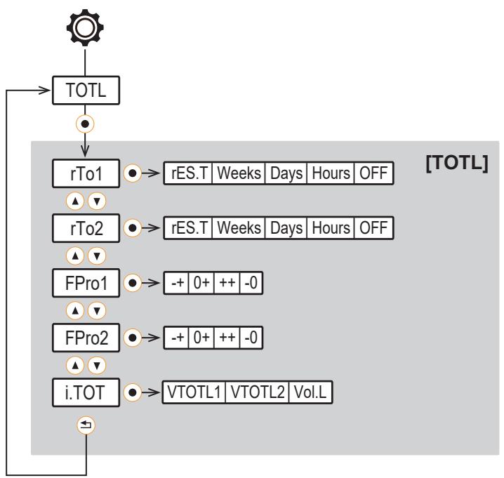
| Parameter | Explanation |
| rTox | Setting for the totaliser reset:Manual reset (= rES. T), time-controlled reset (= weeks, days, hours) or reset via overflow (= OFF) |
| FProx | Counting method of the totaliser: consideration of the direction of flow |
| i. TOT | Indication of totaliser values |
Basic settings menu CFG:
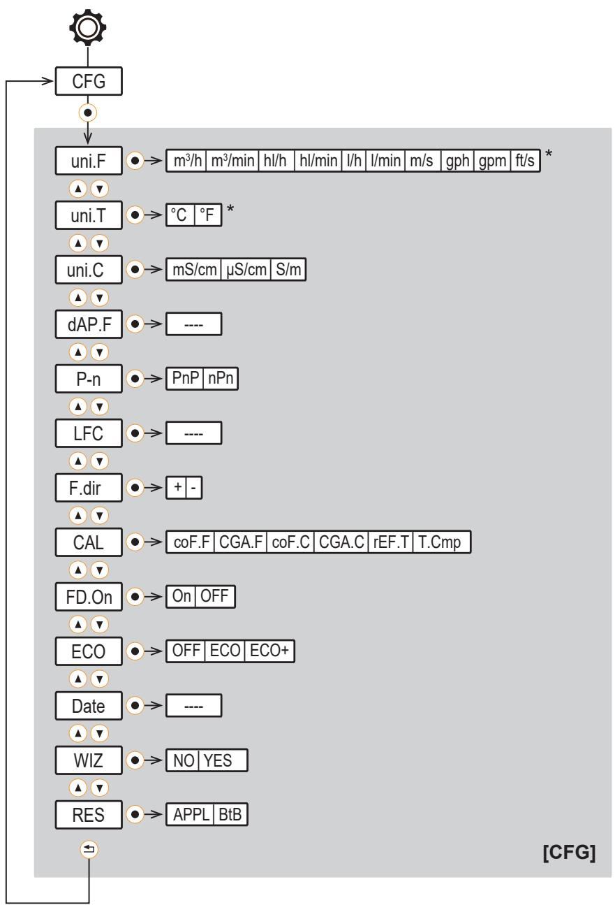
* The options depend on the device type.
| Parameter | Explanation |
| uni. F | Standard unit of measurement for flow |
| uni. T | Standard unit of measurement for temperature |
| uni. C | Standard unit of measurement for conductivity |
| dAP. F | Damping constant in seconds for flow (63 % rise time τ ) |
| P-n | Output polarity for the switching outputs |
| LFC | Low flow cut-off |
| Fdir | Direction of flow |
| CAL | Calibration: zero-point calibration for flow and conductivity (coF.x); measurement characteristic for flow and conductivity (CGA.x); reference temperature (rEF. T) and constant temperature coefficient (T. Cmp) for conductivity. |
| FD. On | Activate or deactivate fluid detection indication via the operating status LED. If On is set, the LED flashes red if no fluid is detected. |
| ECO | Energy-saving mode ECO or ECO+ or energy-saving mode OFF. Setting options for ECO and ECO+: E.dib = display brightness and E. LED = LED ring. Additionally only for ECO+: E.rAt = measuring rate. |
| Date | Real-time clock (date/time) |
| WIZ | Activation of the guided installation |
| rES | Reset to factory settings (Back to Box) or reset of parameter settings (application reset). |
Display menu DIS:
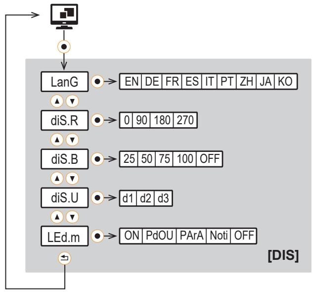
| Parameter | Explanation |
| LanG | Language selection for the display |
| diS. R | Orientation of the display |
| diS. B | Brightness of the display |
| diS. U | Update rate of the display |
| LED.m | LED mode: setting of the operating status LED |
Simulation menu SIM:
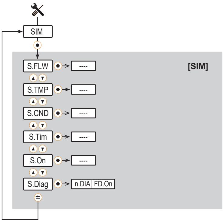
| Parameter | Explanation |
| S. FLW | Simulated flow value in simulation mode |
| S. TMP | Simulated temperature value in simulation mode |
| S. CND | Simulated conductivity value in simulation mode |
| S. Tim | Duration of the simulation in minutes |
| S. On | Starts the simulation mode |
| S. Diag | No diagnostic case simulated (= n. DIA); no medium in the measuring tube (= FD. On) |
10 Set-up
After power on and expiry of the power-on delay time, the unit is in the normal operating mode. It carries out its measurement and evaluation functions and generates output signals according to the set parameters.
During the power-on delay time, the outputs are in the following status according to the set parameters:
• ON for diagnostic function (dOU)
• ON for detection of direction (F. Dir)
• OFF for consumed quantity monitoring (ImP)
• 20 mA for current output (I)

When an IO-Link master is connected, the device automatically goes from SIO mode (standard input-output) into IO-Link mode if the port of the master is set to IO-Link mode.
10.1 Guided installation via an installation wizard
New unboxed and factory reset devices – setup via main menu. When changing from process value display to main menu you will be given the option to use the guided installation wizard (if the device has been set up using IO-Link this option is no longer available).
▶ Select Yes or No.
▷ If Yes is selected, parameters, questions and instructions appear in succession. Use the ▲ and ▼ keys to choose from the available options and the ● key to confirm the selection.
▷ If No is selected, the main menu appears and the sensor functions according to the factory settings. If necessary, change the parameter settings, see chapter Parameter setting.

The guided installation can be called up again at any time via the parameter CFG > WIZ.
After the message that the guided installation is completed, you are asked whether you want to start the measurement.
▶ Select Yes, No or Info.
▷ If Yes is selected, the installation process is completed.
▷ If No is selected, individual parameters can be accessed and modified again, or the guided installation can be restarted from the beginning using the Restart wizard command.
▷ If Info is selected, the device displays the previously set device configuration.
11 Parameter setting
Parameter setting can be carried out via the IO-Link interface or via the operating elements on the unit. Parameters can be set before installation or during operation.

If you change parameters during operation, this will influence the function of the installation. ▶ Ensure that there will be no malfunctions in your installation.
During parameter setting the unit remains in the operating mode. It continues to monitor with the existing parameter until the parameter setting has been completed.

Depending on the parameter setting, the parameters available in the menu may change.
11.1 Parameter setting via the unit keys
Parameters are set on the device using capacitive pushbuttons. The buttons must be pressed firmly with a finger to operate them; they do not respond to touch alone.
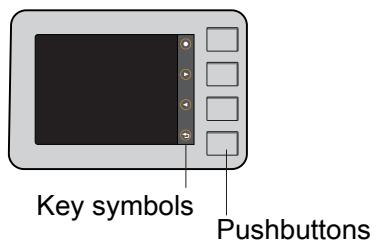

The key symbols on the display show the function of the corresponding device key and may differ in the process value display and the individual menus.
Parameter setting process in general:
| Intention | Action |
| Change from the process value display to the main menu | ◎ * |
| Change from main menu to submenu / other display screens | With ▶ to the symbol, e.g. ✕, then ◎ |
| Select the required parameter / the required display screen | ▲ or ▼ |
| Change to the setting mode / change to lower-level display screens | ◎ |
| Modify the parameter value | ▲ or ▼ |
| Apply the set parameter | ◎ |
| Exit parameter setting without saving | ⇨ or Back in the device menu |
| Return to the next higher menu level (repeat several times to reach process value display) | ⇨ or Back in the device menu |
| Return to the process value display | >30 seconds (timeout) |
Tab. 12: Function of the device keys
* Guided installation is offered for initial set-up ➕ 36.
11.2 Parameter setting via IO-Link
The device parameters can be set via the IO-Link interface in the following ways, for example:
- Parameter setting via a suitable parameter setting software, e.g. ifm moneo|configure
• Parameter setting via a PLC
• Parameter setting via an IIoT application
Requirements for parameter setting via the IO-Link interface:
√ The Input Output Device Description (IODD) for the device in case of parameter setting via a parameter setting software, see documentation.ifm.com
√ The IO-Link interface description (PDF) for the device in case of parameter setting via a PLC or IIoT application, see documentation.ifm.com
√ An IO-Link master
▶ Connect the IO-Link master to the parameter setting software, the PLC or the IIoT application.
▶ Connect the device to a suitable free port of the IO-Link master.
▶ Set the port of the IO-Link master to the IO-Link operating mode.
▷ The device changes to the IO-Link mode.
▶ Change the parameter settings in the software.
▶ Write the parameter settings to the device.

Support for system integration and parameter setting via IO-Link:
→ Manual of the parameter setting software (e.g. moneo)
Explanations and startup packages at ifm.com/cnt/io-link-system-integration.
11.3 Output configuration
11.3.1 Analogue signal
The device provides an analogue signal proportional to the process value.
Within the measuring range the analogue signal is between 4...20 mA.
The measuring range can be scaled between -100% and 100% of the final value of the measuring range.

A negative flow value means flow against the flow direction set under Fdir ➞ 50.
- ASP2 determines at which measured value the output signal is 4 mA.
• AEP2 determines at which measured value the output signal is 20 mA.

Minimum distance between ASP2 and AEP2 = 20 % of the final value of the measuring range.
If the measured value is outside the measuring range or in the event of an internal error, the current signal indicated in the following figure is provided.
For measured values outside the display range or in case of an error, messages are displayed (cr. UL, UL, OL, cr. OL, Err).
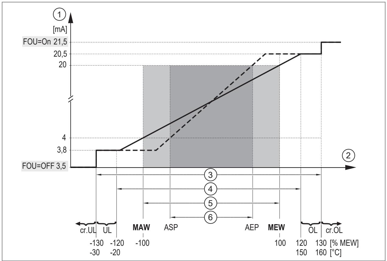
Fig. 16: Characteristics of the analogue output according to the standard IEC 60947-5-7
1: Analogue signal MAW: Initial value of the measuring range
2: Measured value MEW: Final value of the measuring range
3: Detection range ASP: Analogue start point
4: Display range AEP: Analogue end point
5: Measuring range UL: Below the display range
6: Scaled measuring range cr. UL: Below the detection range
OL: Above the display range
cr. OL: Above the detection range

The analogue signal in case of a fault can be set via the parameter FOU ➕ 48. The analogue signal can be stabilised by setting the damping time dAP. F ➕ 48.
Parameter setting via unit keys: Analogue signal
√ The standard unit of measurement is selected: ⚙️ Settings > CFG > uni.x.
▶ Go to ⚙️ menu Settings > OUT2 to configure output OUT2.
▶ Select ou2 and set the function: I (analogue signal 4...20 mA.).
▶ Select SEL2 and set the process value: FLOW, TEMP or COND.
▶ Select ASP2 and set the measurement value at which the output signal is 4 mA.
▶ Select AEP2 and set the measurement value at which the output signal is 20 mA.
11.3.2 Switching signal diagnostics
The device features an integrated diagnostic function. When the diagnostic function is used, a switching signal is provided via the hardware output.
The switching output is switched on in normal operation (normally closed). If the device detects a diagnostic case, the output will be switched off.
Diagnostic cases include:
• reversal of the flow direction ➞ 40
• no medium detected ➞ 40
11.3.2.1 Switching signal for flow direction
A flow direction change can be monitored by providing a switching signal.
The output is switched on until the flow rate falls below the set minimum flow rate in negative flow direction (- LFC)(1).
Then the following applies:
• The output switches ON when + LFC is exceeded (2).
- The output switches OFF when - LFC is not reached (3).

LFC = Low flow cut-off: Low flow cut-off ➕ 49.

Fig. 17: Monitoring of the flow direction by switching signals
+Q: Flow in positive flow direction
-Q: Flow in negative flow direction
+LFC: Minimum flow in positive flow direction
-LFC: Minimum flow in negative flow direction
An arrow with the text “flow direction” on the device indicates the positive flow direction. The direction of the flow measurement can be reversed using the parameter Fdir.
→ Flow direction → 50.
11.3.2.1.1 Parameter setting via unit keys: switching signal for flow direction
▶ Go to ⚙️ menu Settings > OUTx.
▶ Select oux and set dOU.
▶ Select dFUx and set dir. F.
11.3.2.2 Switching signal for fluid detection
The device can provide a switching signal when it cannot detect a medium in the pipe.
The device uses this diagnostic function to identify whether the temperature electrode is wetted by fluid. If this is not the case, the device interprets this as an empty pipe and provides a switching signal. The flow process value is set to zero.


Fig. 18: Fluid detection
1: Medium detected
2: Medium not detected
11.3.2.2.1 Parameter setting via the device keys: Switching signal for fluid detection
▶ Go to ⚙️ menu Settings > OUTx.
▶ Select oux and set dOU.
▶ Select dFUx and set FD.
▷ The OUTx output switches as soon as the device detects no medium in the pipe.
▶ Go to ⚙️ menu Settings > CFG.
▶ Select FD. On and set On.
▷ The operating status LED flashes red as soon as the device does not detect any medium in the pipe.
11.3.3 Consumed quantity monitoring (totaliser function)
The device has 3 internal quantity meters (totalisers VTOTL1, VTOTL2 and Vol. L). The totalisers continuously sum up the consumed quantity and provide this process value both on the display and via the IO-Link interface.
| Totaliser | Process value | Read access via IO-Link |
| VTOTL1 | Consumed quantity 1(This value is used for consumed quantity monitoring by switching or pulse signals) | Cyclic |
| VTOTL2 | Consumed quantity 2 | Acyclic |
| Vol. L | Consumed quantity over the whole lifetime (lifetime totaliser) | Acyclic |
- The totalisers VTOTL1 and VTOTL2 can be reset. Totaliser Vol. L cannot be reset.
→ Totaliser reset → 54. -
The totalisers VTOTL1 and VTOTL2 take account of the following parameter settings when totalising the consumed quantity:
-
Flow direction ➕ 50.
- Counting method of the totalisers ➞ 55.
-
Low flow cut-off ➕ 49.
-
The Life Time Totalisator Vol. L totals all flow quantities regardless of the flow direction and counting method.
- When the detection range (cr. OL) is exceeded, the totalisers use the last valid flow rate value (measuring range end value) and continue counting with this value.
- In addition to the current consumed quantity, the value before the last reset is saved. This value and the time since the last reset can also be displayed ➞ 61.

The totaliser saves the totalled consumed quantity at regular intervals. After a power failure this value is available as the current meter reading. If a time-controlled reset is set, the elapsed time of the set reset interval is also saved. This means that the possible data loss can amount to one minute.
- The accuracy of the consumed quantity measurement depends on the accuracy of the flow measurement.
- A switching signal or pulse signals can be provided for consumed quantity monitoring:
→ Switching signal totaliser → 42.
→ Pulse signal totaliser → 43.

OUT1 and OUT2 cannot be used simultaneously for the consumed quantity monitoring.
11.3.3.1 Switching signal totaliser
A switching signal can be provided for consumed quantity monitoring.
When totaliser VTOTL1 has totalled the flow quantity (pulse value) set under ImPS, the output provides a switching signal.
The flow direction is taken into account when totalling the flow quantity → 55.
The output remains switched until a reset of totaliser VTOTL1 is carried out. When the totaliser has been reset, metering starts again.
▷ The totaliser is reset automatically or manually.
The conditions for the totaliser VTOTL1 reset and the switching signal can be set via the parameter rTo1:
- rTo = OFF:
- The totaliser is only reset with a manual reset or after overflow.
- The output is switched when the totaliser has reached the flow quantity ImPS.
- rTo = ...h / d / w (hours / days / weeks):
- ▷ The totaliser is automatically reset after the set time.
- The output is only switched when the totaliser reaches the flow quantity ImPS by the set time.

The totalisers can be reset manually at any time via the rES. T parameter. Totaliser VTOTL1 can additionally be reset via an external signal at pin 2.
→ Totaliser reset → 54.
11.3.3.1.1 Parameter setting via unit keys: Switching signal totaliser
√ The standard unit of measurement is selected: ⚙ Settings > CFG > uni. F.
√ Only for OUT2: the process value is selected: ⚙️ Settings > OUT2 > SEL2 = FLOW.
▶ Go to ⚙️ menu Settings > OUTx to configure output OUTx.
▶ Select oux and set ImP.
▶ Select ImPSx and set the volumetric flow quantity at which the output switches.
- Press ▲ or ▼ to select the setting range.
- Briefly press • to confirm the setting range.
- Press ▲ or ▼ to set the requested numeric value.
- Briefly press • to apply the value.
▶ Select ImPRx and set No.
▶ Set the rTo1 parameter: Totaliser reset ➞ 54.
11.3.3.2 Pulse signal totaliser
Pulse signals can be provided for consumed quantity monitoring.

Pulse signals are not available via the IO-Link interface.
The output provides a pulse signal each time totaliser VTOTL1 has totalled the flow quantity (pulse value) set under ImPS.
The flow direction is taken into account when totalling the flow quantity → 55.
The pulse signal consists of a short switching on and off of the output.
The pulse width depends on the pulse value and the flow velocity: The greater the pulse value and the lower the flow velocity, the greater the pulse width. This applies up to a pulse width of 2 s. Beyond this, it remains at 2 s.
| DN | Minimum pulse value ImPS1 | ||
| SMFx20 | SMFx21 | ||
| 15 | 1 ml | 2 ml | 0.0005 gal |
| 25 | 1 ml | 4 ml | 0.001 gal |
| 40 | 2 ml | 4 ml | 0.001 gal |
| 50 | 2 ml | 4 ml | 0.001 gal |
| 65 | 4 ml | 38 ml | 0.01 gal |
| 80 | 5 ml | 38 ml | 0.01 gal |
| 100 | 9 ml | 38 ml | 0.01 gal |
| 125 | 13 ml | 38 ml | 0.01 gal |
| 150 | 17 ml | 38 ml | 0.01 gal |
Tab. 13: Lower setting range for ImPS1 by device
11.3.3.2.1 Parameter setting via unit keys: Pulse signal totaliser
√ The standard unit of measurement is selected: ⚙ Settings > CFG > uni. F.
√ Only for OUT2: the process value is selected: ⚙ Settings > OUT2 > SEL2 = FLOW.
▶ Go to ⚙️ menu Settings > OUTx to configure output OUTx.
▶ Select oux and set ImP.
▶ Select ImPSx and set the volumetric flow quantity at which 1 pulse is provided (pulse value).
- Press ▲ or ▼ to select the setting range.
- Briefly press • to confirm the setting range.
- Press ▲ or ▼ to set the requested numeric value.
- Briefly press • to apply the value.
▶ Select ImPRx and set Yes.
11.3.4 Digital switching signal
The device provides digital switching signals via switching signal channels (SSC = Switching Signal Channel).
The device has 2 digital switching signal channels SSCx.1 and SSCx.2 for each process value:
- SSC1.1 and SSC1.2 = switching signal channels for consumed quantity (totaliser)
- SSC2.1 and SSC2.2 = switching signal channels for flow
- SSC3.1 and SSC3.2 = switching signal channels for temperature
- SSC4.1 and SSC4.2 = switching signal channels for conductivity

Explanation of the numbering of the switching signal channels SSCx.y: x = process value; y = switching signal channel
The switching signal channels can only be evaluated via the IO-Link interface.
The parameters for each switching signal channel can be set individually.
During parameter setting, the switch points, mode and logic of the switching signal channels are set.

The parameters for switching signal channels can only be set via the IO-Link interface.
Mode
You can choose between the following modes according to the IO-Link smart sensor profile – Function Class “Quantity Detection”:
- Deactivated
- Single Point Mode
- Two Point Mode
- Window Mode
The switching signal channel changes to the active state depending on the process data value (PDV).

The active state is above the switch point in Single Point Mode and Two Point Mode and within the window section in Window Mode.
Logic
By setting the logic High active or Low active, you can specify which value the switching signal channel has in the active state:
- High active: The switching signal channel is “high” in the active state (= ON = normally open = 1)
- Low active: The switching signal channel is "low" in the active state (= OFF = normally closed = 0)
The following figures show the status of the switching signal channels depending on the mode, logic and process data value (PDV).
Deactivated
If the Deactivated mode is set for a switching signal channel, the switching signal channel will permanently have the following value regardless of the process value:
- For logic High active: permanently "low".
- For logic Low active: permanently “high”.

Fig. 19: Deactivated / High active

Fig. 20: Deactivated / Low active
Single-point mode
Only one switch point SP1 is manually set or taught.
The reset point SP1-H results from the switch point and the set hysteresis.
When teaching, the switch point is set below the taught process value TP1 by the hysteresis.

Fig. 21: Single Point Mode / High active
H: Hysteresis
SP1: Switch point
TP1: Teach point
TP1-H: Switch point during teach (= SP1)
SP1-H Reset point

Fig. 22: Single Point Mode / Low active
H: Hysteresis
SP1: Switch point
TP1: Teach point
TP1-H: Switch point during teach (= SP1)
SP1-H Reset point
Two-point mode
A switch point SP1 and a switch point SP2 are manually set or taught.
The position of the switch points is freely selectable: SP1 can be below or above SP2. The lower switch point is the reset point. In the example shown, SP1 is the setpoint and SP2 is the reset point.
When teaching, the switch point is set directly to the respective taught process value TPx.
The hysteresis will be ignored in Two Point Mode.
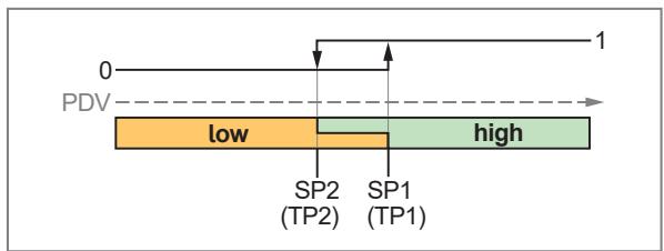
Fig. 23: Two Point Mode / High active
SP1: Switch point 1
SP2: Switch point 2
TP1: Teach point 1 (= SP1)
TP2: Teach point 2 (= SP2)
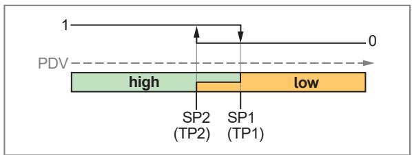
Fig. 24: Two Point Mode / Low active
SP1: Switch point 1
SP2: Switch point 2
TP1: Teach point 1 (= SP1)
TP2: Teach point 2 (= SP2)
Window mode
Two switch points SP1 and SP2 are manually set or taught.
The two switch points define a window area.
The position of the switch points is freely selectable: SP1 can be below or above SP2. The lower switch point is the lower limit value, the higher switch point is the upper limit value of the window area.
When teaching, the switch point is set directly to the respective taught process value TPx.
When the process data value enters the window area, the status of the switching signal channel changes when the switch points are exceeded/not reached.
When the process data value leaves the window area, the status of the switching signal channel changes when the switch point plus/minus the hysteresis is exceeded/not reached.

Fig. 25: Window Mode / High active
H: Hysteresis
SP1: Switch point 1
SP2: Switch point 2
TP1: Teach point 1 (= SP1)
TP2: Teach point 2 (= SP2)

Fig. 26: Window Mode / Low active
H: Hysteresis
SP1: Switch point 1
SP2: Switch point 2
TP1: Teach point 1 (= SP1)
TP2: Teach point 2 (= SP2)
Parameter setting of the switching channels via IO-Link
The switching channels can only be configured via the IO-Link interface.
▶ Set the following parameters:
• Mode SSCx.y Config. Mode
- Switch points SSCx.y Param. SPx
• Hysteresis SSCx.y Config. Hyst
• Logic SSCx.y Config. Logic
- Switch-on delay SSCx.y Switching delay
- Switch-off delay SSCx.y Reset delay
11.3.5 Output off
- The physical hardware outputs OUT1 and OUT2 can be switched off via the parameter oux = OFF . The corresponding output becomes highly resistive so that no signal can be output. The state of the switching channels SSCx.y is still transmitted if the IO-Link connection is active.
- The switching channels can be deactivated individually via the parameter SSCx.y Konfig. Modus = Deactivated. The switching status of the corresponding switching channel is then permanently in the disabled state: With High active setting permanently “low”, with Low active setting permanently “high”.

The parameters for switching signal channels can only be set via the IO-Link interface.
Parameter setting via unit keys: output off
▶ Go to ⚙️ menu Settings > OUTx.
▶ Select oux and set OFF.
11.4 Application configuration
The chapter describes the setting options for adaptation to your specific application.
11.4.1 Standard unit of measurement
A unit of measurement can be selected with which the process value is shown in the display by default. All further parameter settings are based on this unit.
Selectable values:
- uni. F for flow:
- SMFxx0: m/s, l/min, l/h, hl/h, hl/min, m3 /h, m3 /min
- SMFxx1: m/s, l/min, l/h, hl/h, hl/min, m3 /h, m3 /min, ft/s, gpm, gph
• uni. T for temperature:
- SMFxx0: °C - SMFxx1: °C or °F
• uni. C for conductivity:
- SMFxx0: mS/cm, μS/cm, S/m - SMFxx1: mS/cm, μS/cm, S/m
▶ Select the unit of measurement before configuring further parameters for OUTx.
Parameter setting via unit keys: Standard unit of measurement
▶ Go to ⚙️ menu Settings > CFG.
▶ Select uni.x and set the unit of measurement.
11.4.2 Process value for OUT2
For output OUT2, you can select which process value is to be output.

No selection is possible for the OUT1 output. OUT1 is only for monitoring flow.
Selectable values:
- FLOW: Flow
• TEMP: Temperature
• COND: conductivity:
▶ Select the process value before configuring further parameters for OUT2.
Parameter setting via the device keys: Process value OUT2
√ Analogue signal is selected as the output function for OUT2: ⏻ > OUT2 > ou2 = I.
▶ Go to ⚙️ menu Settings > OUT2.
▶ Select SEL2 and set the process value for output OUT2.
11.4.3 Error behaviour of the analogue output
The behaviour of the analogue output OUT2 in the event of an error can be set via the parameter FOU2. The following signals are output in the event of an error:
| FOU2 | SEL2 | Output signal | Explanation |
| ON | FLOWTEMPCOND | In case of an error the output goes to 21.5 mA. | As soon as a defective process value is present, the device sets all process values to invalid. |
| OFF | FLOWTEMPCOND | In case of an error the output goes to 3.5 mA. | |
| OU | FLOW | In case of an error the output goes to 3.5 mA. | If the process value “Flow” is defective, the device continues to provide the other process values. |
| TEMP | In case of an error the output goes to 21.5 mA. | If the process value “Temperature” is defective, the device continues to provide the other process values. | |
| COND | In case of an error the output goes to 3.5 mA. | If the process value “Conductivity” is defective, the device continues to provide the other process values. |

The parameter FOU has no influence on the pulse signal, the diagnostic switching signal and the IO-Link process data transmission.
Parameter setting via unit keys: Error behaviour of the outputs
√ Analogue signal is selected as the output function for OUT2: Ⓞ > OUT2 > ou2 = I.
▶ Go to ⚙️ menu Settings > OUT2.
▶ Select FOU2 and set the error behaviour for output OUT2.
11.4.4 Damping
The set damping constant stabilises the output signals. Abrupt changes in the physical process values are smoothed out.
This concerns the switching outputs, the display and the process value transmission via the IO-Link interface.
The damping constant dAP is used to set after how many seconds the output signal reaches 63% of the final value if the measured value changes suddenly.
The damping constant is added to the response time of the sensor (→ Technical data).
The UL and OL signals are defined under consideration of the damping time.

Measured value damping only has an effect on the process value flow.
Setting range:
0...5 s
Parameter setting via unit keys: Measured value damping
▶ Go to ⚙️ menu Settings > CFG.
▶ Select dAP. F and set the damping time in seconds ( τ value 63%).
11.4.5 Low flow cut-off
Low flow quantities can be ignored using the parameter LFC (Low flow cut-off). Flow below the LFC value is evaluated by the sensor as standstill (Q = 0).
The LFC value influences:
• the process value for flow shown on the display
• the digital switching signal for flow
• the analogue signal for flow
• the memory values for minimum and maximum flow
• the consumed quantity monitoring (switching or pulse signal for flow)
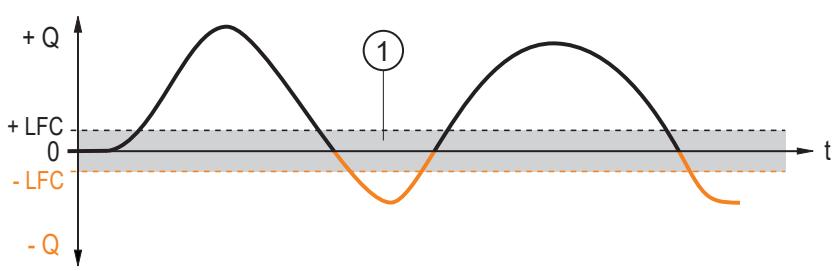
Fig. 27: Low flow cut-off
+LFC: Minimum flow in positive flow direction
-LFC: Minimum flow in negative flow direction
1: Flow which is evaluated as standstill

The unit of the minimum flow rate corresponds to the selection under uni. F.

The accuracy indicated in the data sheet applies to the factory-set LFC value. If a lower LFC value is set, the accuracy of the sensor will decrease.
Parameter setting via unit keys: low flow cut-off
▶ Go to ⚙️ menu Settings > CFG.
▶ Select LFC and set the limit below which a flow is evaluated as standstill.
11.4.6 Output polarity
The output polarity is set via the parameter P-n.
The setting affects both switching outputs.
- PnP: The switching output is positive switching.
- nPn: The switching output is negative switching.
Parameter setting via unit keys: Output polarity
▶ Go to ⚙️ menu Settings > CFG.
▶ Select P-n and set PnP or nPn.
11.4.7 Flow direction
The positive flow direction can be defined by the user. This setting affects the following functions:
• Consumed quantity monitoring (totaliser function) → 41
• Flow direction monitoring via switching signal ➞ 40
An arrow with the text “flow direction” on the device indicates the positive flow direction (factory setting).
The direction of the flow rate measurement can be reversed using the parameter Fdir:
| Fdir | Direction of flow |
| + | Flow direction in case of factory setting |
| - | Flow direction contrary to the factory setting |
Parameter setting via unit keys: flow direction
▶ Go to ⚙️ menu Settings > CFG.
▶ Select Fdir and set the direction of media flow.
11.4.8 Zero calibration
The combination of display unit (converter) and measuring circuit can lead to measurement inaccuracies, particularly depending on the respective ambient conditions.
If there is a systematic deviation between the measured value and the actual process value, this measurement inaccuracy can be corrected using the parameter coF.x.
• coF. F = calibration offset for the flow measurement
• coF. C = calibration offset for the conductivity measurement

The unit for [coF. F] and [coF. C] is the set standard unit of measurement for the process values flow and conductivity → 47.
The internal zero point is shifted by the set value.


Fig. 28: Zero-point calibration (calibration offset)
MEW: Final value of the measuring range
t: time
V0: Curve of measured values at factory setting
V1: Curve of measured values after offset
V2: Curve of measured values after offset
Setting range:
coF. F = -10 % to +10 %; coF. C = -50000 μS/cm to +50000 μS/cm

The parameter is reset to the factory setting both via an application reset and a back-to-box reset.
Factory calibration:
The sensor is calibrated for flow measurement at the factory.
The calibration offset that was used to calibrate the device in the factory can be read on the device or via the IO-Link interface and cannot be configured.
The calibration offset is also listed in the calibration certificate.
Read the factory calibration offset using the device keys:
▶ Go to ⓘ menu Device information and read the calibration offset.
Parameter setting via unit keys: Zero calibration
▶ Go to ⚙️ menu Settings > CFG > CAL.
▶ Select coF.x and set the calibration offset.
11.4.9 Calibration of the measurement characteristic
The calibration factor CGA.x is used to adjust the temperature-viscosity compensation of the sensor to the characteristics of the medium used. The calibration factor influences the gradient of the flow measurement characteristic.
• CGA. F = calibration factor for flow measurement
• CGA. C = calibration factor for conductivity measurement

The slope modification of the measurement characteristic is indicated in percent. The factory setting is CGA = 100%. After a change the calibration can be reset to factory setting.

Fig. 29: Calibration of the measurement characteristic
MW: Measured value
V0: Measurement characteristic at factory setting
V1: Measurement characteristic after offset by +50%
V2: Measurement characteristic after offset by -50%
Setting range:
50 % to 150 %

The parameter is reset to the factory setting both via an application reset and a back-to-box reset.
Factory calibration:
The sensor is calibrated for flow measurement at the factory.
The calibration factor that was used at the factory calibration can be read on the device or via the IO-Link interface and cannot be configured.
The calibration factor is also listed in the calibration certificate.
Reading the factory-set calibration factor via the device keys:
▶ Go to ⓘ menu Device information and read the calibration factor.
Parameter setting via the device keys: calibration of the measurement characteristic
▶ Go to ✅ menu Settings > CFG > CAL.
▶ Select CGA.x and set the gradient of the measurement characteristic in per cent.
11.4.10 Influence of the medium on the temperature
The conductivity depends on the temperature. When the temperature increases, the conductivity changes. This temperature influence depends on the respective medium and can be compensated by the device if the temperature coefficient (TK) of the medium is known.
The temperature compensation is set with the T. Cmp parameter. Then the temperature-compensated conductivity value corresponds to the conductivity at standard temperature (25 °C; factory setting of the parameter rEF. T).
For medium that is not changed the same TK value has to be set for all sensors (device-independent characteristic value). There is no further dependence on the measuring principle, the lot or the manufacturer of the sensors.
If the temperature coefficient of the medium is not known, it can be determined. → Determination of the temperature coefficient tempco
In an IO-Link environment, existing TK values of the media can be stored as recipe in the controller so that the accuracy of the values to be detected is improved.
Determining the temperature coefficient TK
▶ Set the parameters T. Cmp and dAP to zero: T. Cmp = 0, dAP = 0.
▶ Write the changed values to the sensor.
▶ Adjust the medium to 25\ °C , for example, and take down the value of the conductivity after 2 minutes.
▶ Heat up the medium to 45\ °C , for example, and take down the value of the conductivity after 2 minutes.
Example of values taken down:
Medium at 25° C = 500 µ S/cm; medium at 45° C = 800 µ S/cm; temperature change = 20 K
▶ Calculate the change of the conductivity in percent.
▷ The conductivity has increased by 300 µ S/cm. The percentage change is 300/500 = 60 %.
▶ Calculate the temperature coefficient TK: the TK is calculated from the change in percent and the temperature change: TK = 60 % / 20 K = 3 % / K
▶ The calculated TK can now be adopted into the parameter T. Cmp.
Example: T. Cmp = 3. If necessary, set the damping (parameter dAP) again.
▶ Write values to the sensor.
11.4.10.1 Parameter setting via the device keys: Temperature compensation
▶ Go to ⚙️ menu Settings > CFG > CAL.
▶ Select T. Cmp and set the temperature coefficient of the medium.
▶ Select rEF. T and enter the standard temperature.
11.4.11 Date and Time
Setting the date and time serves to provide events and measurements with a time stamp.
For this, the date and time must be set during set-up. When setting the time, wither a 12hr or 24hr format can be chosen. If the time is not set, the clock will start from an initial value (2024/01/01).

The device contains an internal energy storage unit so that, in the event of a power failure, the settings are saved for a transitional period. If the power supply is interrupted for too long, the display will show the ⏻ symbol and the message that the date and time are no longer set.
▶ Reset the date and time.
Parameter setting via the device keys: Date/time
▶ Go to ⚙️ menu Settings > CFG.
▶ Select Date and set the date and time:
• Date: year, month, day
• Clock format: 24h or 12h
• Time: hour, minute

▶ Change numerical values with ▼or ▲.
▶ Confirm numerical value and jump to next setting with Ⓞ.
11.4.12 Energy-saving mode
The device can be operated in energy-saving mode.
The ECO parameter can be used to select between two energy-saving levels: ECO and ECO+.
The energy-saving mode is switched off via the OFF setting.
Both energy-saving modes can be configured via the parameters E.dib and E. LED. In ECO+ mode, the measuring rate can also be set.
| ECO = | Setting options | ||
| Display brightnessE.dib | Operating status LDE. LED | Measuring rateE.rAt | |
| [ECO] | 25 %, 50 %, 75 %, 100 %, OFF | On, OFF, Noti, PdOU, PArASee Operating status LED ➕ 63 | --- |
| [ECO+] | Current measuring rate*:60...900 s | ||
Tab. 14: Setting options for the two energy-saving modes.
* The accuracy indicated in the data sheet applies to the factory settings. Changing the measuring rate in ECO+ mode has a direct impact on the sensor's measurement accuracy.

If ECO = OFF is set, the general settings for Display brightness and Operating status LED → 63 apply.
Parameter setting via the device keys: Energy-saving mode
▶ Go to ⚙️ menu Settings > CFG.
▶ Select ECO and set the mode: OFF, ECO or ECO+.
▶ Select E.dib and set the display brightness: 25 %, 50 %, 75 %, 100 %, OFF.
▶ Select E. LED and select the display options for the operating status LED: On, OFF, Notification, PA-rA, PdOU.
Only if ECO+ is selected
▶ Select E.rAt and set the measuring rate.
11.4.13 Totaliser reset
The totalisers VTOTL1 and VTOTL2 can be reset in different ways:
| Type of reset | Parameter | |
| 1. | Manual reset | rTox = rES. T |
| 2. | Time-controlled reset | rTox = ... Hours = reset after ... hours ... Days = reset after ... days ... Weeks = reset after ... weeks |
| 3. | Reset via external signal | ou2 = In. DDIn2: +EDG = reset for rising edge -EDG = reset for falling edge HIGH = reset for high signal LOW = reset for low signal |
| 4. | Reset via overflow (maximum display range is reached) | rTox = OFF |

Only totaliser VTOTL1 can be reset via an external signal.
Totaliser Vol. L cannot be reset.
If totaliser VTOTL1 is reset in one of the above ways, the output is also reset in the case of consumed quantity monitoring.
→ Switching signal totaliser → 42.
Parameter setting via unit keys: Totaliser reset
1. Manual reset:
▶ Go to ⚙️ menu Settings > TOTL.
▶ Select rTox and set rES. T.
▷ The totaliser is reset.
2. Time-controlled reset:
▶ Go to ⚙️ menu Settings > TOTL.
▶ Select rTox, then set time in weeks (w), days (d) or hours (h).
The totaliser is automatically reset after the set time.
3. Reset via external signal:
▶ Go to ⚙️ menu Settings > OUT2.
▶ Select ou2 and set digital input: In. D.
▶ Select DIn2 and set the reset signal: HIGH, LOW, +EDG or -EDG.
▷ The totaliser is reset when receiving the reset signal via pin 2.
4. Reset via overflow:
▶ Go to ⚙️ menu Settings > TOTL.
▶ Select rTox and set OFF.
The totaliser is reset as soon as the maximum display range is exceeded.
11.4.14 Counting method of the totalisers
The totalisers VTOTL1 and VTOTL2 take account of the flow direction when totalising the consumed quantity. The following counting methods can be defined via the parameter FProx:
| FProx | Counting method |
| 0+ | Negative volumetric flow values (against the marked flow direction) are not taken into account for totalling. |
| -0 | Positive volumetric flow values (corresponding to the marked flow direction) are not taken into account for totalling. |
| -+ | Negative flow values are subtracted from the consumed quantity. |
| ++ | All volumetric flow values are totalled irrespective of the volumetric flow direction. |
Tab. 15: Counting method of the totalisers
The counting method of Vol. L cannot be set. The lifetime totaliser totals all volumetric flow quantities irrespective of the flow direction.
The counting method affects the output signals for consumed quantity monitoring.
→ Consumed quantity monitoring (totaliser function) → 41.

Fig. 30: Taking into account the flow direction when totalling the consumed quantity
+Q: Flow quantity in positive direction
-Q: Flow quantity in negative direction
V: Flow quantity absolute (= sum of negative and positive flow)
1: Flow changes to negative direction
2: Flow changes to positive direction
3: Flow taken into account for totalisation
When the direction of flow is changed, the minimum flow quantity LFC is taken into account.
→ Low flow cut-off → 49.
Parameter setting via unit keys: counting method of the totalisers
▶ Go to ✅ menu Settings > TOTL.
▶ Select FPro1 and set the counting method for totaliser VTOTL1.
▶ Select FPro2 and set the counting method for totaliser VTOTL2.
11.4.15 Reset the device
The device can be reset in two ways.

With both reset applications, the operating hours since the first set-up are not reset.
APPL = application reset
The following is reset to the factory setting:
- All parameters and device settings except the device identification parameters such as Application Specific Tag, Function Tag and Location Tag.

If IO-Link data storage is activated, this immediately triggers a parameter update in the master.
BtB = Back to Box
The following is reset to the factory setting:
- All parameters and device settings including the device identification parameters such as Application Specific Tag, Function Tag and Location Tag.
• Diagnostic parameters, status parameters, events.
• Minimum and maximum memory value

After the Back to Box reset, the sensor suspends communication and measurement operation until the voltage is interrupted. The IO-Link data storage is not triggered.
Resetting the device using device keys
▶ Go to ⚙️ menu Settings > CFG > RES.
▶ Select APPL or BtB and set Yes.
Only if BtB is selected:
▶ Disconnect and reconnect the voltage supply.
▷ The device carries out a reboot.
11.5 Display settings
The presentation in the display can be adjusted via various parameters.
The parameters described below are set either in the ☐ Display menu, via the IO-Link interface or the wizard.
11.5.1 Display language
The display language can be set via the parameter LanG.
Selectable languages:
• DE: German
• EN: English
• ES: Spanish
- FR: French
- IT: Italian
• JA: Japanese
• KO: Korean
• PT: Portuguese
- ZH: Chinese
Parameter setting via unit keys: display language
▶ Go to the 📋 Display menu.
▶ Select LanG and set the language.
11.5.2 Display rotation
Use the parameter diS. R to rotate the text in the display clockwise for better readability.
Selectable values:
- 0° (not rotated)
• 90°
• 180°
• 270°
Parameter setting via unit keys: display rotation
▶ Go to the 📋 Display menu.
▶ Select diS. R and set the display rotation.
11.5.3 Display brightness
The display brightness can be set via the parameter diS. B.
Selectable values:
• 25%
- 50%
• 75%
• 100 %
• OFF: the display is switched off in the operating mode.
Display activation by pressing any key. After 30 s of inactivity, the display is switched off again.

In case of warnings or error messages and in case of optical localisation, the display will come back on even with the setting OFF.

If the device measures a high internal temperature, the display brightness is automatically adjusted:
Internal temperature > 75 °C: brightness is reduced to 25%.
Internal temperature ≥ 90 ° C: display is automatically switched off.
Parameter setting via unit keys: display brightness
▶ Go to the 📋 Display menu.
▶ Select diS. B and set the brightness of the display.
11.5.4 Display update rate
The update rate of the display can be set via the parameter diS. U.
Selectable values:
- d1: fast
- d2: medium
- d3: slow
Parameter setting via unit keys: display update rate
▶ Go to the 📋 Display menu.
▶ Select diS. U and set the update rate.
11.5.5 Display layout
The standard display can be set via the parameter diS. L.

This function is only available via the IO-Link interface or the wizard ➞ 67.
A maximum of 4 of the following displays can be selected for the standard display:
- Process value current flow
- Process value current consumed quantity (totaliser)
- Process value current temperature
• Process value current conductivity
• Arrow for flow direction ➕ 27


Fig. 31: Display layouts
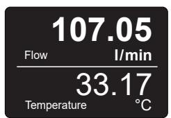

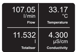
Fig. 32: Examples of layout settings. The order of the process values is freely selectable.
Parameter setting via the device keys: Display layout
▶ Go to ⚙️ menu Settings > CFG.
▶ Select WIZ, confirm with YES and select dis. L.
▶ Select a display layout.
▶ Select the process values one after the other: FLOW, TOTL, F_Dir, TEMP, COND (a maximum of 4 out of 5 possible).
11.5.6 Display colour setting

This function is only available via the IO-Link interface.
The font colour in the display can be set via the parameter col.x.
• coL. F: font colour for flow
• coL. T: font colour for temperature
• coL. C: font colour for conductivity
The colour can be defined individually for each process value using the following parameter settings.

The font colour for the totaliser cannot be set.
Permanent colour selection

Fig. 33: Example: coL. F = bk/wh
The font colour is permanently white on a black background:
| coL. F = | coL. T = | coL. C = | Font colour |
| bk/wh | White | ||
Colour change depending on freely definable limit values
If the measured value is within the limits of cFL.x...cFH.x, the following applies depending on the parameter selection:
| coL. F = | coL. T = | coL. C = | Font colour |
| r-cF | red | ||
| G-cF | green | ||

A

B

Fig. 34: Example: temperature coL. T = bk/wh; A: flow coL. F = r-cF; B: conductivity coL. C = G-cF
The limit values of the window range can be freely selected within the measuring range and are independent of the output function:
- Flow: cFL. F = lower limit value; cFH. F = upper limit value
• Temperature: cFL. T = lower limit value; cFH. T = upper limit value - Conductivity: cFL. C = lower limit value; cFH. C = upper limit value
Configuration of colour setting via IO-Link
The colour setting can only be made via the IO-Link interface.
▶ Set the following parameters:
• Colour configuration: coL. F; coL. T; coL. C.
Only for coL.x = r-cF or G-cF:
• Lower value for colour change: cFL. F; cFL. T; cFL. C.
• Upper value for colour change: cFH. F; cFH. T; cFH. C.
11.6 Diagnostics
The device continuously monitors itself during operation and provides the results of its self-diagnosis in the following ways:
• The device shows a message on the display ➞ 69.
- The device indicates a warning or error by changing the colour of the LED ring ➕ 63.
- The device provides diagnostic messages as a switching signal or via the IO-Link interface ➞ 39.
In addition, the following diagnostic information can be read via the display and/or the IO-Link interface:
- Read totaliser values ➞ 61
- Memory → 62
• Operating hours counter → 62
• Internal temperature ➕ 62
• Operating status LED ➕ 63
• Event history ➕ 63
11.6.1 Read totaliser values
For the totalisers VTOTL1 and VTOTL2 and the lifetime totaliser Vol. L, the following values can be read at any time on the display or via the IO-Link interface:
Totaliser values VTOTL1 and VTOTL2
- Current flow quantity (= consumed quantity since the last totaliser reset)
• Value before the last totaliser reset
• Time since the last totaliser reset
Totaliser values Vol. L (lifetime totaliser for the entire operating time)
• Volumetric flow quantity in preferred direction (= positive flow direction)
• Volumetric flow quantity in non-preferred direction (= negative flow direction)
• Total flow quantity (= positive + negative flow direction)
Reading totaliser values on the device
▶ Go to ⚙️ menu Settings > TOTL.
▶ Open the i. TOT.
▶ Select the totaliser and read the consumed values.
11.6.2 Memory
The unit stores the maximum and minimum measured process values.
The current value can be read from the unit's display or via the IO-Link interface.
Selectable values:
- minimum flow value
• maximum flow value
• minimum temperature value
• maximum temperature value
• Minimum conductivity value
• Maximum conductivity value

It makes sense to delete the memories as soon as the unit operates under normal operating conditions for the first time.
Show memory:
▶ Go to ☐ menu Diagnostics.
▶ Select Lo.x or Hi.x to show the highest or lowest process value measured.
Clear memory:
▶ Go to ☐ menu Diagnostics.
▶ Lo.x or Hi.x > select Reset and Yes.
▷ The memory for process value x (F = flow, T = temperature or C = conductivity) is reset.
11.6.3 Operating hours counter
The operating hours since the first set-up are stored by the unit.
The current value can be read from the unit's display or via the IO-Link interface.

In case of a voltage interruption, no more than the count of the last hour will be lost.
Read operating hours on device
▶ Go to ☐ menu Diagnostics.
▶ Select Operating hours and read value.
11.6.4 Internal temperature
The sensor measures the internal temperature.
The current value can be read from the unit's display or via the IO-Link interface.
A high internal temperature is signalled by the operating status LED ring turning red.

If the device measures a high internal temperature, the display brightness is automatically adjusted:
Internal temperature > 75 °C: brightness is reduced to 25%.
Internal temperature ≥ 90 ° C: display is automatically switched off.
Read internal temperature on device
▶ Go to ☐ menu Diagnostics.
▶ Select Internal temperature and read value.
11.6.5 Operating status LED
The device is equipped with an operating status LED ring, which is clearly visible from all sides and shows the current status of the device ➕ 27:
| LED signal | Device status |
| LED ring flashes red (1 Hz) | Device operating outside the specification. The device does not detect any medium in the pipe (only with setting CFG > FD. On = On). |
| LED ring red | Error |
| LED ring blue | Maintenance required |
| LED ring green | Voltage supply and operation normal |
Tab. 16: Status signals in compliance with Namur NE107 standard
If several diagnostic events occur simultaneously, only the diagnostic message of the event with the highest priority is displayed.
→ Warning messages → 69
→ Error messages → 70
The function and colour of the operating status LED can be changed:
| LED mode | Operating status LED |
| On | The LED ring is permanently on. Green in normal operation, blue or red for diagnostics. |
| OFF | The LED ring is permanently off. |
| Noti | The LED ring is off during normal operation. The LED ring is only on for diagnostics (blue or red). |
| PdOU* | The LED ring is controlled via the IO-Link process data interface PD OUT. |
| PArA* | The LED ring is permanently lit in the set colour (red, green, blue or yellow). |
*can only be set via IO-Link
Parameter setting via unit keys: operating status LED
▶ Go to the 📄 Display menu.
▶ Select LED.m and set operating status LED.

To activate the operating status LED for fluid detection ➞ 40:
▶ Call up menu ⚙️ Settings > CFG > FD. On and set On.
11.6.6 Event history
The device records incoming and outgoing events with an event description and time stamp. For this, it is important that the date and time are set on the sensor ➞ 53.
The last 20 events can be read on the device display.
A total of 200 events can be saved on the device. These can be exported from the device via the IO-Link interface → 66.
Read events on device
▶ Go to ☐ menu Event History and read the events.
11.7 Service functions
11.7.1 Device information
Unalterable device information is stored on the unit. This includes:
- Product name
- Product family
- Manufacturer
- Manufacturer ID
- Device ID
- Serial number
• Hardware / firmware revision - Description
In addition, further freely definable tags with a maximum length of 32 characters can be assigned to the unit via the IO-Link interface using suitable parameter setting software. This includes:
- application-specific tag
- function tag
- location tag
Reading device information on the device
▶ Go to ⓘ Device information menu and read the device information.
11.7.2 Configuration
All the device settings can be shown on the device display via the Service menu. The parameters, currently set values and original factory settings are shown in a list.
Read settings on the device.
▶ Go to the ✗ Service menu > o. CFG.
▶ Select Current settings.
▷ Only the parameters that have been changed from the factory settings are listed.
- or -
▶ Select All settings.
▷ All parameters are listed.
11.7.3 Simulation
With this function, process values are simulated and their signal path is checked.
Process values that lead to an error message or warning can be simulated (e.g. OL).
When the simulation is started, the values of the totaliser are frozen and the simulated totaliser is set to 0. The simulated flow value then has an effect on the simulated totaliser. When the simulation is ended, the initial totaliser values are restored.
During the simulation:
- The simulation has no effect on the current process values. The outputs operate as previously set.
- The original totaliser value remains saved without any changes even if there is a real flow.
- No error messages of the current application are available. They are suppressed by the simulation.
The following values can be simulated:
- Process values for flow, temperature and conductivity
- process values outside the measuring range (cr. UL, UL, OL, cr. OL)
• The sensor is receiving no data (NoData)
• No medium in the measuring pipe (Fluid Detection).
Parameter setting via unit keys: simulation
▶ Go to ✗ menu Service > SIM.
▶ Select S. FLW and set the flow value to be simulated.
▶ Select S. TMP and set the temperature value to be simulated.
▶ Select S. CND and set the conductivity value to be simulated.

The parameters crUL, UL, OL, crOL and NoData become visible only when the value is above or below the measuring range during throughput.
▶ Select S. DIAG and select settings:
• n. DIA: Device operating normally
• FD. On: No medium in the measuring pipe
▶ Select S. Tim and set the time of the simulation in minutes.
▶ Select S. On and set the function:
- On: The simulation starts. The values are simulated for the time set under S. Tim. Abort by pressing any key.
• OFF: The simulation is not active.
11.7.4 Documents
The device display can show QR codes which link directly to further product information on the website www.ifm.com.


This function is not available via the IO-Link interface.
Read QR codes on device
▶ Go to the ✕ Service menu > QR.
▶ Press the keys ▶ and ◀ to show the desired QR code.
▶ Scan the QR-code using a smartphone camera and open the link that appears on the smartphone.
11.7.5 Binary data transmission (BLOB)
The device offers a function for reading binary data from the device as one large file (BLOB = Binary Large Object).
The data is exported as a BIN file.
This requires a software tool (e.g. ifm moneo) that supports the IO-Link BLOB interface.
The BIN file contains the following logbook information:
• device information for identification
• number of operating hours
- event logging:
– event history with time stamp
- event code
– event description
- event frequency
- device restarts
Only the last 200 events are saved.

In case of a voltage interruption, the events of the last 10 minutes can be lost.
11.7.6 Optical localisation
The sensor can be located remotely in the system via the IO-Link interface.
When using the command Locator Start, the LED ring flashes green.
▶ Exit the function with the command Locator Stop.

If the function is not terminated by command, the status LED stops flashing automatically after 10 minutes.
11.7.7 Lock / unlock
The unit can be locked electronically to prevent unauthorised setting.
This lock prevents the settings from being changed via the keys on the unit.
Factory setting: not locked.
Parameter setting via unit keys: lock / unlock
Locking:
▶ Make sure that the unit is in the normal operating mode.
▶ Press the ◀ and ▶ keys simultaneously for approx. 10 s until menu locked is displayed.
Unlocking:
▶ Make sure that the unit is in the normal operating mode.
▶ Press the ◀ and ▶ keys simultaneously for approx. 10 s until menu unlocked is displayed.
11.7.8 Guided installation (wizard)
The wizard can be used to help set the parameters via the device keys.
This guided installation will be offered on the display the first time the device is switched on ➞ 36 and can be launched at any time after that via the WIZ parameter.
Guided installation via the device keys
▶ Go to ⚙️ menu Settings > CFG.
▶ Select WIZ.
▶ Use the keys to set the parameters displayed one after the other and confirm each with ●.
▷ Once all the requested parameters have been set, the installation is completed with a success message and the device changes to the process value display.

The settings can be shown on the device display: Configuration ➞ 64.
12 Operation
After power on and expiry of the power-on delay time, the unit is in the normal operating mode. It carries out its measurement and evaluation functions and generates output signals according to the set parameters.
13 Troubleshooting
The unit has many self-diagnostic options. It monitors itself automatically during operation.
Warnings and error states are displayed even if the display is switched off. Error indications are also available via IO-Link.
The status signals are classified according to NAMUR recommendation NE107.
If several diagnostic events occur simultaneously, only the diagnostic message of the event with the highest priority is displayed.
In addition, warning and error messages are displayed by the device as follows:
- Switching signals when using the diagnostic function → 39.
• Colour signals of the operating status LED ➕ 63.
If a process value fails, the other process values are still available. Exception: If the process value for flow fails, no other process values are output.

Additional diagnostic functions are available via IO-Link ➕ IO-Link interface description at documentation.ifm.com.
13.1 Warning messages
| Status* | Display | Operating status LED | IO-Link event | Problem | Solution | |
| Title line | Process value display | |||||
| 2 | Temperature overrun | Current valid process values | red, flashing (1 Hz) | 0x4210 | Admissible device temperature exceeded. | ▶ Eliminate heat sources. |
| 2 | Internal temperature | Current valid process values | red, flashing (1 Hz) | 0x4220 | Admissible device temperature not reached. | ▶ Insulate device. |
| 3 | alternately: "Simulation active" / "Application Tag" | Simulated process value | depending on the simulated value | 0x8C01 | Simulation active. | ▶ Stop simulation. |
| 2 | Upper limit | OL | red, flashing (1 Hz) | 0x8C10 | Process value above the valid range. | ▶ Check the application. |
| 2 | Lower limit | UL | red, flashing (1 Hz) | 0x8C30 | Process value below the valid range. | ▶ Check the application. |
| 1 | Interface disturbed | Current valid process values | blue | 0x8CE0 | Local user interface disturbed. | ▶ Check the device's user interface. |
| 2 | No medium detected | 0 | red, flashing (1 Hz) | 0x8CC1 | Measuring tube not sufficiently filled or medium has too low conductivity. | ▶ Check the application. ▶ FD. On = OFF set. ➕ 63 |
Tab. 17: Warning messages. * Status: 1 = maintenance required; 2 = outside the specification; 3 = function test

In case of a warning the analogue output behaves according to the setting FOU = OU. Exception: Short circuit.
13.2 Error messages
| Status* | Display | Operating status LED | IO-Link event | Problem | Corrective measures | |
| Title line | Process value display | |||||
| 4 | Device error | ---- | red | 0x5000 | Hardware error in the device / device is defective. | ► Replace the device. |
| 3 | Component malfunction | All process values that are still valid. The defective process value is displayed as “Err”. | red flashing (1 Hz) | 0x5010 | A process value is defective. | ► Repair or replace the device. |
| 3 | Parameter error | PArA | red | 0x6320 | Parameter error | ► Perform a back-to-box reset. |
| 3 | Short circuit | SC OUTx | red flashing (1 Hz) | 0x7710 | Short circuit | ► Check device wiring. |
| 3 | Critical limit | cr. OL | red flashing (1 Hz) | 0x8C20 | Measurement range exceeded | ► Check the application. |
| 3 | Critical limit | cr. UL | red flashing (1 Hz) | 0x8C20 | Measurement range underrun | ► Check the application. |
Tab. 18: Warning messages. * Status: 3 = function test; 4 = failure

In case of a fault the analogue output behaves as set under FOU2.
14 Maintenance, repair and disposal
The goods can only be replaced if the product seal on the packaging is not damaged.
A defective device can be returned to the manufacturer for repair.
Only the manufacturer is allowed to repair the unit.
▶ In case of return shipment, ensure that the unit is free from soiling, especially from dangerous and toxic substances.
14.1 Maintenance
Calibration:
▶ Define regular calibration intervals according to the process requirements. Recommendation: every 12 months.
More frequent calibration may be necessary when used in particularly demanding environments. Examples:
• High temperature load
• High mechanical loads (vibration and shock)
• Use of media that tend to form deposits

ifm calibration service ➕ Calibration certificates at www.ifm.com.
Cleaning the seals:
▶ Regularly check the two seals between the device and the process adapter for deposits and damage.
- ▶ Clean the device from dirt using a soft, chemically untreated and dry micro-fibre cloth, or replace the seals. The time between replacing the seals depends on the frequency of the cleaning cycles, the media temperature and the cleaning temperature.
Cleaning the device:
▶ Before cleaning the device, activate the button lock.

If the buttons are not locked, unintentional button pushes can occur due to temperature changes or pressure being applied by a high-pressure cleaner. In extreme cases, it may take up to one minute for the button to be actively reset by the software.
▶ Do not touch the measuring electrodes with your fingers when cleaning the device ➕ 9.

Touching the electrodes with your fingers, especially when touching the temperature electrode, can lead to measurement deviations in conductivity. Finger perspiration and finger grease influence the measurement signal.
14.2 Replacing the electronic unit
A defective electronic unit can be replaced with a new one by the customer.

An electronic unit with display cannot be replaced by an electronic unit without display. Information about suitable accessories at www.ifm.com.

When replacing the electronic unit, the original factory calibration certificate loses its validity as the serial number on the factory calibration certificate does not match the serial number of the new electronic unit.
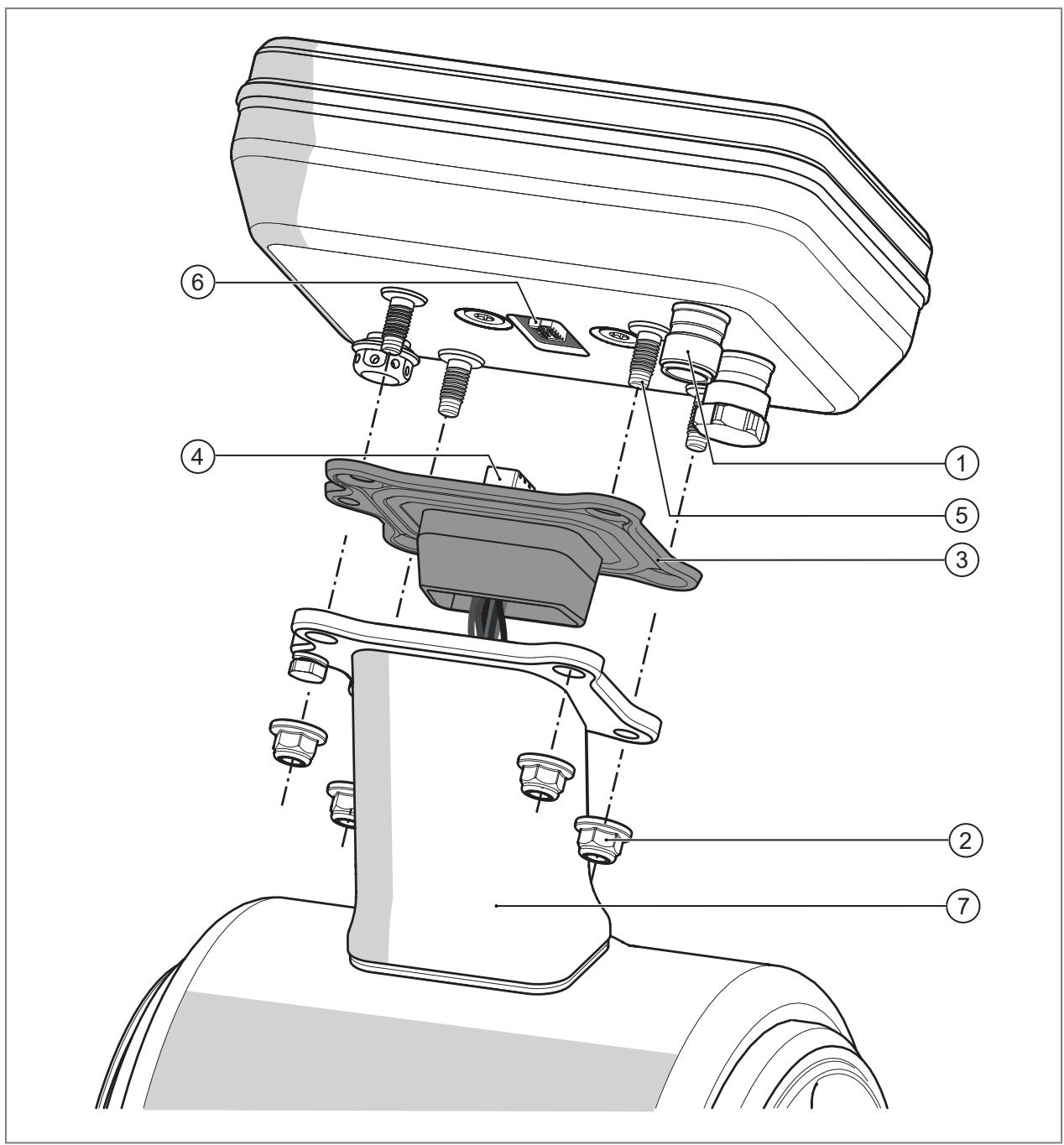
Fig. 35: Mounting / removal
1: Connector for electrical connection
2: 4 x M5 hexagon nuts
3: Seal (firmly bonded to circuit board and socket)
4: Circuit board with socket (permanently wired to the electronics in the measuring tube)
5: Threaded bolt
6: Plug of the electronic unit
7: Bracket

The electronic unit is supplied without a seal. In case of replacement, the original seal is reused.

CAUTION
Risk of electric shock
▷ Touching live parts can result in personal injury.
▶ Ensure that the power supply is disconnected before installing or removing the electronic unit.
How to proceed:

ATTENTION
Damage to the device when replacing the electronic unit
▷ Improper replacement will invalidate the warranty.
▶ Ensure that the internal cabling is not damaged.
▶ Ensure that ingress of moisture and foreign substances is avoided when the device is open.

Fig. 36: Unscrew the defective electronic unit.
▶ Loosen the connector for the electrical connection (1).
▶ Loosen the four M5 hexagonal nuts (2) at the bottom of the electronic unit.
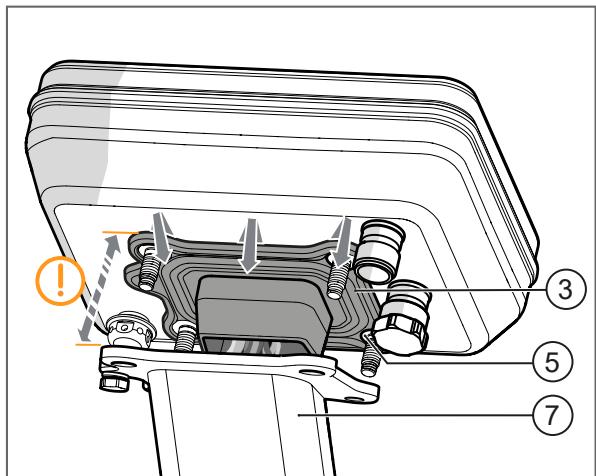
Fig. 37: Remove seal.
▶ Lift the defective electronic unit slightly off the bracket (7).
▶ Remove the seal (3) from the threaded bolts (5).

Do not pull the cabling too far out of the bracket.

Fig. 38: Remove the defective electronic unit.
▶ Remove the seal together with the circuit board and socket (4) from the electronic unit to release the plug connection.

Do not pull the cabling too far out of the bracket.
▶ Remove the faulty electronic unit.

Fig. 39: Connect the new electronic unit.
▶ Have the new electronic unit ready.
▶ Carefully plug the socket (4) onto the plug (6) of the new electronic unit.

Do not pull the cabling too far out of the bracket.
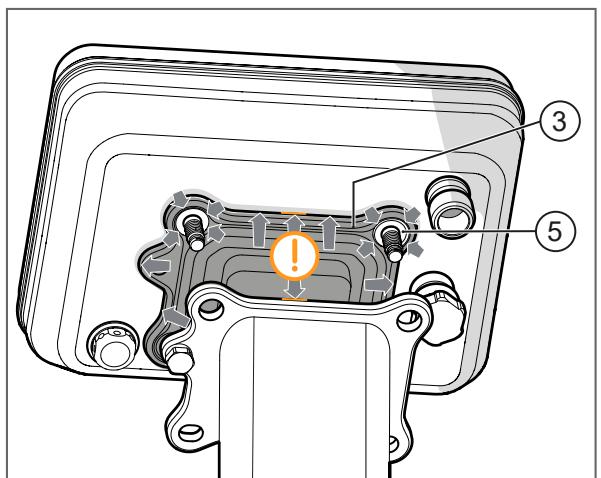
Fig. 40: Install the seal.
▶ Press the seal (3) with the four outer holes precisely onto the collar of the four threaded bolts (5) of the new electronic unit.

Do not pull the cabling too far out of the bracket.
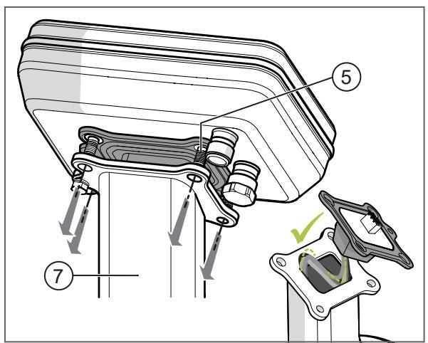
Fig. 41: Install the new electronic unit.
▶ Insert the new electronic unit with the threaded bolts (5) into the holes of the bracket (7).

Do not pinch the cabling. If the cabling has been pulled out too far, insert it into the bracket in an S-shape without kinks.

Fig. 42: Screw on the new electronic unit.
▶ Screw the new electronic unit to the bracket (7) using the four M5 hexagon nuts (2). Tightening torque: 4 Nm.

The seal must lie completely flat against the electronic unit.
▶ Restore the electrical connection via the connector (1).
▷ The device carries out a reboot.

When rebooting, the electronic unit automatically adopts the basic data relevant to the measuring tube (e.g. nominal width, calibration, device type). All other parameter settings are reset to the factory setting.
▶ Reconfigure the device.
14.3 Disposal
▶ After use dispose of the product or components in an environmentally friendly way in accordance with the applicable national regulations.
▶ Dispose of used batteries in accordance with national environmental regulations. Do not dispose of used batteries as household waste.
15 Factory settings
General settings:
| Parameter | Factory setting | ||
| uni. F | SMFxx0: m3/h | SMFxx1: gpm | |
| uni. T | SMFxx0: °C | SMFxx1: °F | |
| uni. C | µS/cm | ||
| FPro1 | 0+ | ||
| FPro2 | 0+ | ||
| rTo1 | OFF | ||
| rTo2 | OFF | ||
| dAP. F | 0.6 | ||
| P-n | PnP | ||
| LFC | SMF120: 0.06 m3/h SMF220: 0.15 m3/h SMF320: 0.3 m3/h SMF420: 0.6 m3/h SMF520: 1.2 m3/h SMF620: 1.8 m3/h SMF720: 3.0 m3/h SMF820: 4.5 m3/h SMF920: 6.0 m3/h | SMF121: 0.26 gpmSMF221: 0.66 gpmSMF321: 1.4 gpmSMF421: 2.6 gpmSMF521: 5.5 gpmSMF621: 8.0 gpmSMF721: 13.0 gpmSMF821: 20.0 gpmSMF921: 26.0 gpm | |
| F.dir | + | ||
| coF. F | 0 | ||
| CGA. F | 100 | ||
| rEF. T | 25 °C | ||
| diS. R | 0 | ||
| LanG | EN | ||
| diS. L | L1 | ||
Settings for OUT1:
| Parameter | Factory setting | |
| ou1 | ImP | |
| ImPS1 | SMF120: 0.0002 ISMF220: 0.001 ISMF320: 0.002 ISMF420: 0.002 ISMF520: 0.004 ISMF620: 0.005 ISMF720: 0.009 ISMF820: 0.013 ISMF920: 0.017 I | SMF121: 0.0005 gallonsSMF221: 0.001 gallonsSMF321: 0.001 gallonsSMF421: 0.001 gallonsSMF521: 0.01 gallonsSMF621: 0.01 gallonsSMF721: 0.01 gallonsSMF821: 0.01 gallonsSMF921: 0.01 gallons |
| ImPR1 | YES | |
| dFu | dir. F | |
Settings for OUT2:
| Parameter | Factory setting | |
| ou2 | I / 4...20 mA | |
| SEL2 | FLOW | |
| ASP2 | SMFx20: 0 m3/h | SMFx21: 0 gpm |
| AEP2 | SMF120: 2 m3/h SMF220: 4 m3/h SMF320: 11 m3/h SMF420: 18 m3/h SMF520: 30 m3/h SMF620: 45 m3/h SMF720: 70 m3/h SMF820: 110 m3/h SMF920: 160 m3/h | SMF121: 7 gpmSMF221: 20 gpmSMF321: 50 gpmSMF421: 80 gpmSMF521: 130 gpmSMF621: 200 gpmSMF721: 310 gpmSMF821: 485 gpmSMF921: 700 gpm |
| FOU2 | OFF | |
| dFu | dir. F | |
| DIn2 | +EDG | |
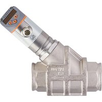
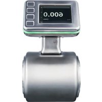
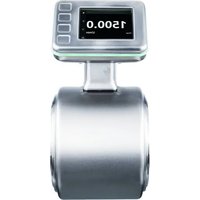
- 1 PRELIMINARY NOTE
- 1.1 SYMBOLS USED
- 1.2 WARNINGS
- 2 SAFETY INSTRUCTIONS
- 2.1 CYBERSECURITY
- 3 TRANSPORT, HANDLING AND STORAGE
- 4 INTENDED USE
- 4.1 APPLICATION AREA
- 5 FUNCTION
- 5.1 OUTPUT OUT1 SELECTION OPTIONS
- 5.2 OUTPUT OUT2 SELECTION OPTIONS
- 5.3 IO-LINK
- 6 MOUNTING
- 6.1 DEVICE DIMENSIONS
- 6.2 INSTALLATION POSITION
- 6.3 INLET AND OUTLET PIPE LENGTHS
- 6.4 PROCESS CONNECTION
- 6.4.1 CLAMP ADAPTERS
- 6.4.2 WELDING ADAPTER
- 6.4.3 SCREW ADAPTER
- 6.4.4 FLANGE ADAPTER
- 6.5 USE IN HYGIENIC AREAS
- 6.6 USE IN HYGIENIC AREAS ACCORDING TO 3-A
- 7 ELECTRICAL CONNECTION
- 8 OPERATING AND DISPLAY ELEMENTS
- 9 MENU
- 9.1 MAIN MENU
- 9.2 SUBMENUS
- 10 SET-UP
- 10.1 GUIDED INSTALLATION VIA AN INSTALLATION WIZARD
- 11 PARAMETER SETTING
- 11.1 PARAMETER SETTING VIA THE UNIT KEYS
- 11.2 PARAMETER SETTING VIA IO-LINK
- 11.3 OUTPUT CONFIGURATION
- 11.3.1 ANALOGUE SIGNAL
- 11.3.2 SWITCHING SIGNAL DIAGNOSTICS
- 11.3.2.1 SWITCHING SIGNAL FOR FLOW DIRECTION
- 11.3.2.2 SWITCHING SIGNAL FOR FLUID DETECTION
- 11.3.3 CONSUMED QUANTITY MONITORING (TOTALISER FUNCTION)
- 11.3.3.1 SWITCHING SIGNAL TOTALISER
- 11.3.3.2 PULSE SIGNAL TOTALISER
- 11.3.4 DIGITAL SWITCHING SIGNAL
- 11.3.5 OUTPUT OFF
- 11.4 APPLICATION CONFIGURATION
- 11.4.1 STANDARD UNIT OF MEASUREMENT
- 11.4.2 PROCESS VALUE FOR OUT2
- 11.4.3 ERROR BEHAVIOUR OF THE ANALOGUE OUTPUT
- 11.4.4 DAMPING
- 11.4.5 LOW FLOW CUT-OFF
- 11.4.6 OUTPUT POLARITY
- 11.4.7 FLOW DIRECTION
- 11.4.8 ZERO CALIBRATION
- 11.4.9 CALIBRATION OF THE MEASUREMENT CHARACTERISTIC
- 11.4.10 INFLUENCE OF THE MEDIUM ON THE TEMPERATURE
- 11.4.11 DATE AND TIME
- 11.4.12 ENERGY-SAVING MODE
- 11.4.13 TOTALISER RESET
- 11.4.14 COUNTING METHOD OF THE TOTALISERS
- 11.4.15 RESET THE DEVICE
- 11.5 DISPLAY SETTINGS
- 11.5.1 DISPLAY LANGUAGE
- 11.5.2 DISPLAY ROTATION
- 11.5.3 DISPLAY BRIGHTNESS
- 11.5.4 DISPLAY UPDATE RATE
- 11.5.5 DISPLAY LAYOUT
- 11.5.6 DISPLAY COLOUR SETTING
- 11.6 DIAGNOSTICS
- 11.6.1 READ TOTALISER VALUES
- 11.6.2 MEMORY
- 11.6.3 OPERATING HOURS COUNTER
- 11.6.4 INTERNAL TEMPERATURE
- 11.6.5 OPERATING STATUS LED
- 11.6.6 EVENT HISTORY
- 11.7 SERVICE FUNCTIONS
- 11.7.1 DEVICE INFORMATION
- 11.7.2 CONFIGURATION
- 11.7.3 SIMULATION
- 11.7.4 DOCUMENTS
- 11.7.5 BINARY DATA TRANSMISSION (BLOB)
- 11.7.6 OPTICAL LOCALISATION
- 11.7.7 LOCK / UNLOCK
- 11.7.8 GUIDED INSTALLATION (WIZARD)
- 12 OPERATION
- 13 TROUBLESHOOTING
- 13.1 WARNING MESSAGES
- 13.2 ERROR MESSAGES
- 14 MAINTENANCE, REPAIR AND DISPOSAL
- 14.1 MAINTENANCE
- 14.2 REPLACING THE ELECTRONIC UNIT
- 14.3 DISPOSAL
- 15 FACTORY SETTINGS
Brand : IFM
Model : SMF720
Category : Flow Meter