RM 4223 - Fridge DOMETIC - Free user manual and instructions
Find the device manual for free RM 4223 DOMETIC in PDF.

User questions about RM 4223 DOMETIC
0 question about this device. Answer the ones you know or ask your own.
Ask a new question about this device
Download the instructions for your Fridge in PDF format for free! Find your manual RM 4223 - DOMETIC and take your electronic device back in hand. On this page are published all the documents necessary for the use of your device. RM 4223 by DOMETIC.
USER MANUAL RM 4223 DOMETIC
Model No. Serial No.
Product No
Date Purchased Place of Purchase
USA
SERVICE OFFICE
The Dometic Corp.
509 So. Poplar St.
La Grange, IN 46761
Phone: 219 463 4858
CANADA
Dometic Dist.
866 Langs Dr.
Cambridge, Ontario
Canada N3H 2N7
Phone: 519 653 4390
FOR SERVICE CENTER
ASSISTANCE
CALL: 800 544 4881

text_image
SP CERTIFIED
text_image
DESIGN CERTIFIED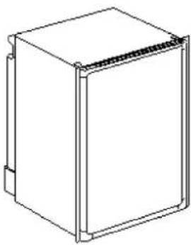
natural_image
Line drawing of a rectangular box with a side panel and mounting bracket (no text or symbols)REFRIGERATOR MODEL
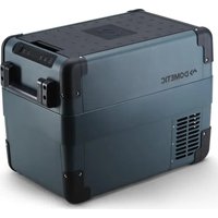
RM 4223
For Mobile Home or Recreational Vehicle Installation
Operation by LP Gas, 12V DC or 120V AC
FOR CHILD SAFETY
DANGER: Risk of child entrapment. Before you throw away your old refrigerator: Take off the doors, leave the shelves in place, so that children may not easily climb inside.
FOR YOUR SAFETY
If you smell gas:
- Shut off gas supply at main valve.
- Open windows.
- Don't touch electrical switches.
- Extinguish any open flame.
- Immediately call your gas supplier.
FOR YOUR SAFETY
Do not store or use gasoline or other flammable vapors and liquids in the vicinity of this or any other appliance.
WARNING
Improper installation, adjustment, alteration, service or maintenance can cause injury or property damage. Refer to this manual. For assistance or additional information consult a qualified installer, service agency or the gas supplier.
AVIS
Operating Instructions 7
Maint. & Service 10
Français page 13
IMPORTANT INSTRUCTIONS
READ CARFULLY
1. GENERAL INSTRUCTIONS
This appliance is designed for storage of food and storage of frozen food and making ice.
The refrigerators outlined herein have been design certified by A.G.A. under ANSI Z21.19 Refrigerator Standard for installation in a mobile home or recreational vehicle and are approved by the Canadian Gas Association. The certifications are, however, contingent on the installation being made in accordance with the following instructions as applicable.
In the U.S.A., the installation must conform with:
- National Fuel Gas Code ANSI Z223.1-(latest edition)
- Manufactured Home Construction and Safety Standard, Title 24 CFR, Part 3280
- Recreational Vehicles ANSI A119.2-(latest edition).
The unit must be electrically grounded in accordance with the National Electric Code ANSI/NFPA 70-(latest edition) when installed if an external alternating current electrical source is utilized.
- Any applicable local code.
In Canada, the installation must conform with:
- Current CGA B 149 Gas Installation Codes
- Current CSA Standard Z 240.4 GAS-EQUIPPED RECREATIONAL VEHICLES AND MOBILE HOUSING
- Any applicable local code
The unit must be electrically grounded in accordance with the CANADIAN ELECTRICAL CODE C 22 Parts 1 and 2.
2. VENTILATION
The installation shall be made in such a manner as to separate the combustion system from the living space of the mobile home or recreational vehicle. Louver openings must have a minimum dimension of 1/4 inch for air supply or venting of combustion products.
Proper installation requires one fresh air intake and one upper exhaust vent. The ventilation kits shown in this instruction manual have been certified for use with the refrigerator model listed in the Table. For "Certified Vent System Kits" see Section B. The ventilation kits must be installed and used without modification. An opening toward the outside at floor level in the refrigerator compartment must be provided for ventilation of heavier-than-air fuel gases. The lower vent of the recommended kits is provided with properly sized openings. The flow of combustion and ventilation air must not be obstructed. The lower side vent is fitted with a panel which provides an adequate access opening for ready serviceability of the burner and control manifold of the refrigerator. This should be centered on the back of the refrigerator.
3. CERTIFIED INSTALLATION
Certified installations require one upper side vent and one lower side vent.
For certified vent system kits, see Section B.
For further information, contact your dealer or distributor.
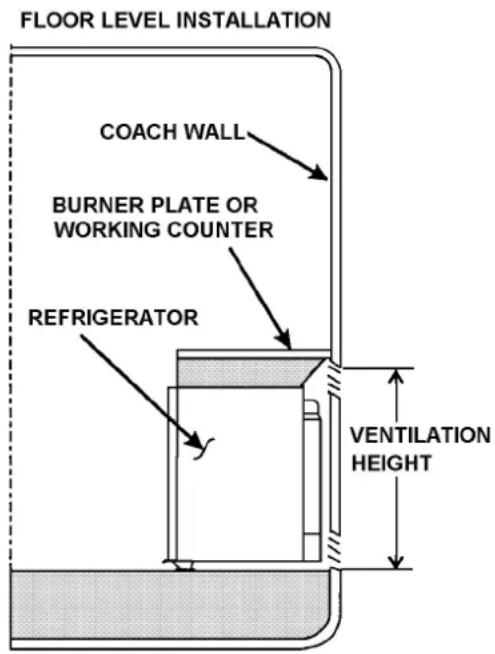
4. METHOD OF INSTALLATION
The methods of installation are shown in FIG. 1 & FIG. 1A. It is essential that all maximum or minimum dimensions are strictly maintained as the performance of the refrigerator is dependent on adequate flow of air over the rear of the refrigerator.
NOTE: The upper vent should be centered over the condenser coil at the back of the refrigerator.
FIG.1
text_image
FLOOR LEVEL INSTALLATION COACH WALL BURNER PLATE OR WORKING COUNTER REFRIGERATOR VENTILATION HEIGHTFIG.1a
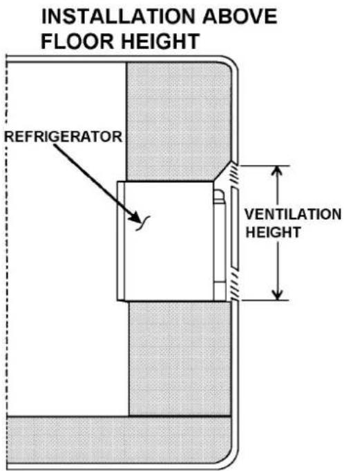
text_image
INSTALLATION ABOVE FLOOR HEIGHT REFRIGERATOR VENTILATION HEIGHT5. VENTILATION HEIGHTS
Refer to FIG 1 & FIG. 1A., Pages 1 & 2
| Installation with Upper side vent And lower side vent | * Minimum Ventilation Height “N” | |
| REFRIGERATOR | INCHES | MM |
| RM 4223 Metal Side Vents 21.0 533 (2) RM 183 Vents | ||
| RM 4223 Plastic Side Vents (1) 3107560.041 22.0 558.8 (1) 3107560.009 | ||
| * These dimensions represent the minimum height allowable. It is recommended the Upper Vent be located to the maximum possible height of the vehicle for optimum performance in warmer climates. | ||
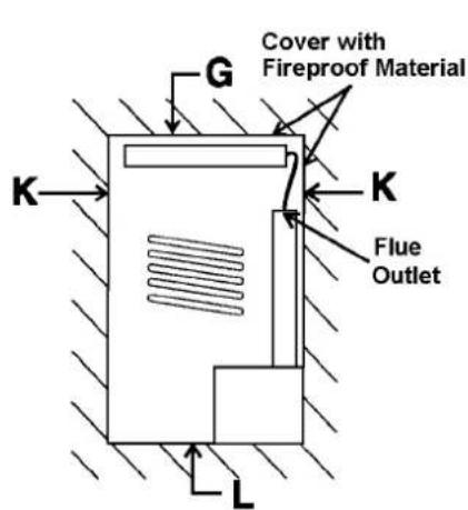
6. CLEARANCES
Minimum clearances in inches to combustible materials are:
G: T o p 0 "
K: Side 0"
L: Bottom 0"
M: Rear 9/32"
N: See NOTE
P: See NOTE
NOTE: Clearance "M" is between the rearmost part of the refrigerator and the wall behind the refrigerator.
NOTE: Clearance "N" is the distance between the bottom of the lower vent to the top of upper side vent. For ventilation height, refer to Section A. Installation, Item 5. Ventilation Heights. See FIG. 2.
Surfaces directly above and sides adjacent to the flue outlet must be of, or covered with, fireproof material. See FIG. 2.
NOTE: Clearance "P" over top of unit condenser fins is 1/4 inch. This is the minimum height which can be allowed over the condenser fins. Whenever possible, increase this height by up to 11 inches; the more ventilation you provide, the better the performance you can expect from the refrigerator.
text_image
G Cover with Fireproof Material K K Flue Outlet LFig. 2
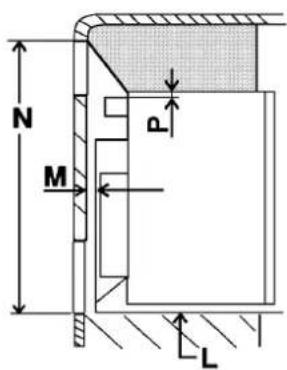
text_image
N M P L7. INSTALLING REFRIGERATOR IN ENCLOSURE
NOTE: DO NOT install the appliance directly on carpeting. Carpeting must be removed or protected by a metal or wood panel beneath the appliance, which extends at least the full width and depth of the appliance.
The dimensions shown in FIG.3 will give you adequate space for service and proper installation.
FIG. 3
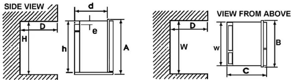
| RM 4223 Overall Installation Recess Distance between Dimensions Dimensions Dimensions Top of condenser and | Top of refrigerator | ||||||||||
| Vent Type | Height A | Width B | Depth C | Heighth | Width w | Depth d | Height H | Width W | Depth D | e | |
| Dual Metal (inches) | 21-7/32 | 21-5/32 | 25-6/32 | 20-21/32 | 19-11/32 | 23-23/32 | 20-29/32 | 19-9/16 | 24 | 1/4" | |
| Side Vents (mm) | 539 | 537 | 641,5 | 524,5 | 491 | 602,5 | 530,5 | 497 | 610 | 6 | |
| Dual Plastic (Inches) | 21-7/32 | 21-5/32 | 25-6/32 | 20-21/32 | 19-11/32 | 23-23/32 | 20-29/32 | 19-9/16 | *24 | 1/4" | |
| Side Vents (MM) | 539 | 537 | 641,5 | 524,5 | 491 | 602,5 | 530,5 | 497 | *610 | 6 | |
| * Depth "D" Dimensions Requirement with Plastic Vent System is Dependant on Vehicle Side Wall Thickness. If the Vehicle Side Wall Thickness is less than 1,5 inches (38mm), the Recessed Depth Dimensions will be required to be Increased Proportionally to the Vehicle Wall Thickness. | |||||||||||
A. INSTALLATION
The refrigerator must be installed in a substantial enclosure and must be level. When installing the refrigerator in the enclosure, all areas within the recess in which the refrigerator is installed must be sealed from the living space.
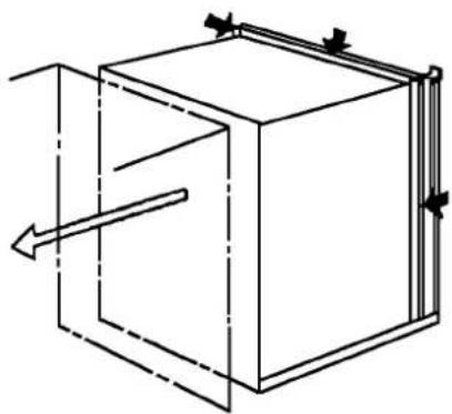
Make sure that there is a complete seal between the front frame of the refrigerator and the top, sides and bottom of the enclosure. A length of sealing strip is applied to the rear surface of the front frame for this purpose, see FIG. 4. The sealing should provide a complete isolation of the appliance's combustion system from the vehicle interior.
Note: Be careful not to damage the sealing strip when refrigerator is put in place.
FIG. 4
natural_image
Pure technical line drawing of a 3D cube with internal arrows indicating direction (no text or symbols)B. SECURING REFRIGERATOR IN ENCLOSURE
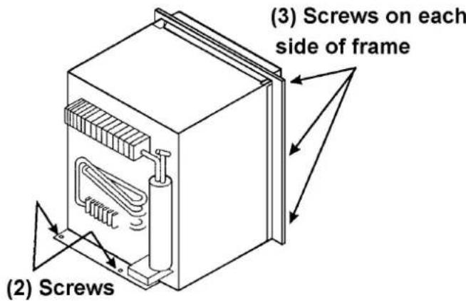
The refrigerator is installed in the enclosure with eight screws. Six screws are in the front frame and two are in the plate on the rear. See FIG. 5.
FIG. 5
text_image
(2) Screws (3) Screws on each side of frameNOTE: Push refrigerator into enclosure until front frame is tight against the cabinet. First, secure the frame to cabinet with six screws. Second, install the two screws to the floor at the rear of the refrigerator.
Failure to follow the sequence in securing the refrigerator in the enclosure can cause leakage between the frame and cabinet. Any space between the counter, storage area or ceiling and top of the refrigerator should be blocked. The heat produced at the rear of the refrigerator will become trapped in this space, making the top of the refrigerator hot and reducing the efficiency.
The dimensions shown in FIG. 3 will give you adequate space for service and proper installation.
8. GAS CONNECTION
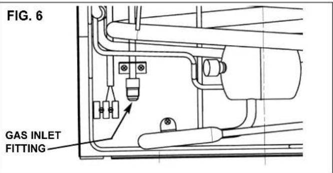
Hook-up to the gas supply line is accomplished at the manual gas shutoff valve, which is furnished with a 3/8" SAE (UNF 5/8" - 18) male flare connection. Always use a backup wrench when connecting the gas supply line to the gas inlet fitting. All completed connections should be checked for leaks with a noncorrosive leak detector. (See FIG. 6 - Gas inlet fitting may have a different orientation than shown).
! WARNING
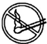
DO NOT use a flame to check for gas leaks.
text_image
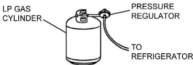
FIG. 6 GAS INLET FITTINGThe gas supply system must incorporate a pressure regulator to maintain a supply pressure of not more than 13.5 inches water column, static (no load).
text_image
LP GAS CYLINDER PRESSURE REGULATOR TO REFRIGERATORWhen testing the gas supply system at test pressures in excess of 1/2 psig, the refrigerator and its individual shutoff valve must be disconnected from the gas supply piping system.
When testing the gas supply system at pressures less than or equal to 1/2 psig, the appliance must be isolated from the gas supply piping by closing its individual manual shutoff valve.
In case detailed instructions on the installation and connection to the gas supply are required, contact your dealer or distributor.
9. TESTING LP GAS SAFETY SHUTOFF
The gas safety shutoff must be tested after the refrigerator is connected to LP gas supply.
To test the gas safety shutoff, proceed as follows:
A. Start the refrigerator according to the instructions for LP Gas Operation. See "Section C. Operation Instructions."
B. Check that the gas flame is lit. Allow it to burn a few minutes to ensure a full, stable flame.
C. Turn the gas safety valve (D, FIG. 8) to the "OFF" position. Within 1-2 minutes the gas safety device within the valve should automatically close. An audible "click" from the valve may be heard.
D. Turn the gas safety valve to the "ON" position (D, FIG. 8).
E. Without pushing in the knob (D, FIG. 8) of the gas safety device, apply a commercial leak detection solution to the burner jet. No bubbles should appear. Bubbles indicate a gas leak and the safety valve must be replaced by a qualified serviceman.
F. Rinse the burner jet with water. Light the burner and allow it to burn for five minutes.
10. 120 VOLT AC ELECTRICAL CONNECTION
The refrigerator is equipped with a three-prong (grounded) plug for protection against shock hazards, and should be plugged directly into a properly grounded three-prong receptacle. DO NOT cut or remove the grounding prong from this plug. The power cord should be routed to avoid direct contact with the burner cover, fuel cover or manual gas shutoff valve knob.
11. 12 VOLT DC CONNECTION
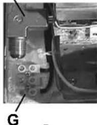
The 125 watt heating element operates the cooling unit when the refrigerator is connected to the battery of the vehicle. It has a current rating of about 10.5 amps; therefore, the wiring from the battery to the refrigerator must be of heavy enough gauge to carry this load satisfactorily without undue voltage drop. To ensure this, the minimum size of wire to be used is 14 A.W.G. The terminal block for connecting the 12V supply cable to the battery is positioned at the lower lefthand corner of the rear side (G, FIG. 8). From this terminal, the connection to the battery should be made using ring-type clamps with tightening bolts to ensure good contact with the battery terminals. Polarity is not important, therefore it does not matter which wire leads to which battery terminal.
DO NOT connect lights or any other electrical components to the same circuit that is used by the refrigerator.
IMPORTANT:
To prevent the refrigerator from being left on and draining the battery when the vehicle's engine is not running and charging the battery, it is recommended that an automatic cutout relay be installed between the battery and the refrigerator toggle switch so that the refrigerator will not draw current when the vehicle ignition is switched off. Alternatively, a suitable plug and receptacle should be installed in the 12V supply line so that the refrigerator can be disconnected from the supply, as necessary.
FUSE
A 12 amp (continuous rating) fuse should be incorporated in the wiring of the DC supply, as near to the battery as possible. The fuse must be in the side of the wiring which is not connected to the chassis. For example, if the vehicle has a negative ground, the fuse must be in the positive side of the wiring.
12. CHANGING DOOR HINGES FROM ONE SIDE TO THE OTHER
If required, the door hinges can be moved to the opposite side. Reverse the door hang in the following way:
A. Unscrew the upper hinge pin, taking care not to lose the set of washers and bushings.
B. Lift the door from the lower hinge pin. If decorative door panel is to be installed, proceed to Step 13.
C. Unscrew the pin and mount it on the opposite side hinge.
D. Unscrew the travel catch and mount it on the opposite side.
E. Replace door on lower hinge pin. Replace upper hinge pin and bushings removed in Step A.
F. Check that the door closes properly and seals all around.
13. INSTALLATION OF DECORATIVE DOOR PANEL
The door panel can easily be mounted. The dimensions of the panel must be:
Height 19-3/4"
Width 17-27/32"
Thickness Up to 1/8"
Weight 49 lbs.
A. Remove the door. See Section 12.
B. Remove the lower trim molding. (NOTE: Trim molding is not installed on new units in cartons)
C. Fit the new panel in place and slide it up as far as possible.
D. Fit the trim molding back in place.
SECTION B. CERTIFIED VENT SYSTEMS
| VENT KIT OPTIONS COMPONENTS PART NO. | ||
| DUAL METAL SIDE VENTS * RM 183 | * RM 183 Upper Metal Side Vent | 8030211.332 |
| Upper Metal Side Vent 8030211.332 | ||
| ** Power Ventilator Optional | 3108705.751 | |
| DUAL PLASTIC SIDE VENTS * Lower Pl | * Upper Plastic Side Vent | 3107560.041 |
| plastic Side Vent 3107560.009 | ||
| ** Power Ventilator Optional | 3108705.751 | |
| * Vent System Requires One Each. ** Alternative instructions forwarded with ventilator kit. Used in conjunction with upper and lower side vents at minimum vent heights for optimum performance. | ||
SECTION C. OPERATING INSTRUCTIONS
1. IMPORTANCE OF LEVELING A REFRIGERATOR
In an absorption refrigerator system, ammonia is liquefied in the finned condenser coil at the top of the refrigerator. The liquid ammonia then flows into the evaporator (inside the freezer section) and is exposed to a circulating flow of hydrogen gas, which causes the ammonia to evaporate, creating a cold condition in the freezer.
The tubing in the evaporator section is specifically sloped to provide a continuous movement of liquid ammonia downward by gravity through this section. If the refrigerator is operated when it is not level and the vehicle is not moving, liquid ammonia will accumulate in sections of the evaporator tubing. This will slow the circulation of hydrogen and ammonia gas, or in severe cases, completely block it, resulting in a loss of cooling.
Remember to level the vehicle when stopping for more than an hour, otherwise the cooling unit could be permanently damaged due to overheating if it is left "ON".
When the vehicle is moving, the leveling is not critical as the rolling and pitching motion of the vehicle will pass to either side of level, keeping the liquid ammonia from accumulating in the evaporator tubing.
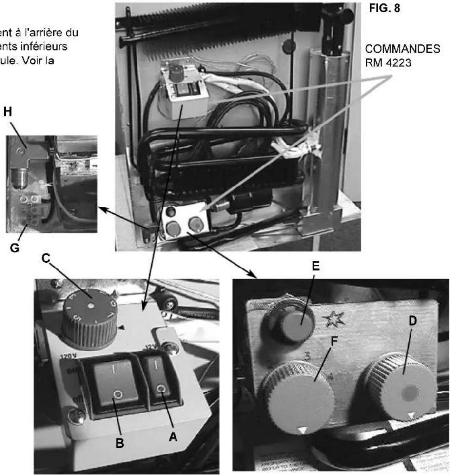
2. CONTROLS
The gas and electric controls are located at the rear of the refrigerator and are accessible through the lower vents in the outside wall of the vehicle. See FIG. 8.
A = DC ON/OFF SWITCH
B = AC ON/OFF SWITCH
C = ELECTRIC
THERMOSTAT
D = GAS ON/OFF VALVE
E = PIEZO IGNITER
F = GAS THERMOSTAT
G = DC TERMINAL BLOCK
H = GAS INLET FITTING
H
natural_image
Close-up of a mechanical component with labeled point G (no readable text or symbols)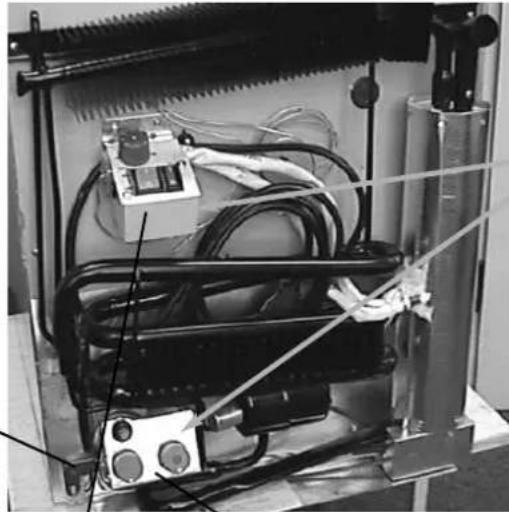
natural_image
Interior view of an industrial machine with coiled tubing, wires, and control panel (no visible text or symbols)FIG. 8
CONTROLS
RM 4223
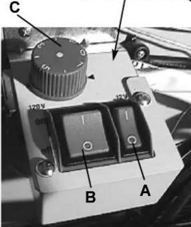
text_image
C 120V 015 B AE
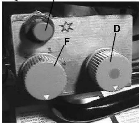
text_image
F D3. OPERATING INSTRUCTIONS
A. LP GAS OPERATION
After initial installation, servicing, or changing gas cylinders, etc., the gas line may contain some air which should be allowed to escape by briefly turning on the refrigerator or other gas appliances. This will ensure that the flame lights immediately. See FIG. 8 for control location and identification.
1) Open the shutoff valve of the gas bottle. Check that there is enough gas. Open any on-board shutoff valve which is in the gas line to the refrigerator.
2) Open the lower vent at the rear of the refrigerator on the outside of the vehicle, and switch the electrical toggle switches A and B to the "OFF" position.
3) Turn the gas thermostat control (F) to the highest setting.
4) Depress the knob (D) of the flame failure device, turn it to position "ON", and hold it down while depressing the piezo igniter button (E) several times in quick succession (a click should be heard each time it is depressed).
5) Keep the knob depressed for a further 10-15 seconds.
6) Release the knob and check for flame by looking through the opening in the metal burner cover.
7) If the burner has not lit, repeat the lighting procedure. If the burner fails to light within a couple of attempts, contact a qualified technician or your dealer.
NOTE: The refrigerator has a flame failure device which will automatically shut off the gas to the burner if the flame is blown out. While the knob (D) is being held in, this device is temporarily inoperative.
8) If the ambient temperature is above 80^ F and/or the door of the refrigerator is opened frequently the knob (F) should be left in higher position.
9) To terminate gas operation, turn knob (D) to the "OFF" position.
DO NOT attempt to operate the refrigerator by both gas and electricity at the same time. Always ensure that one method of operation is turned off before using the alternate energy source.
! WARNING
Most LP gas appliances used in recreational vehicles are vented to the outside of the vehicle. When parked close to a gasoline pump, it is possible that the gasoline fumes could enter this type of appliance and ignite from the burner flame, CAUSING A FIRE OR AN EXPLOSION.
FOR YOUR SAFETY, it is recommended that all LP gas appliances which are vented to the outside should be shut off when refueling.
The refrigerator must be shut off during refueling.
In the case of the RM4223, the refrigerator works continuously on DC operation (no thermostat control).
On AC operation, the temperature is controlled by a thermostat. The thermostat knob (C, in FIG. 8) should be set to position 4-5 in normal working conditions. If the ambient temperature is high and/or fresh food is put into the refrigerator you may set the refrigerator to a higher setting.
If you wish a higher temperature in the cooling compartment, set the knob to a lower position.
3. TO TERMINATE ELECTRIC OPERATION
To terminate electric operation, turn switches (A and B) to the "OFF" position.
NOTE: NEVER OPERATE THE REFRIGERATOR ON MORE THAN ONE ENERGY SOURCE AT A TIME.
4.HOW TO USE THE REFRIGERATOR
A. FOOD STORAGE COMPARTMENT
The storage compartment is completely closed and unventilated, which is necessary to maintain the required low temperature for food storage. Consequently, foods having a strong odor or those that absorb odors easily should be covered. Vegetables, salads, etc. should be covered to retain their crispness. The coldest positions in the refrigerator are under the cooling fins and at the bottom of the refrigerator. The warmer areas are on the upper door shelves. This should be considered when placing different types of food in the refrigerator.
The refrigerator is designed for the storage of fresh foods, milk, etc. It is not intended for the storage of frozen food. The internal volume of the refrigerator is 2,5 cubic feet, net.
Avoid using large dishes and do not stack food or food containers too closely as this interferes with the circulation of cold air within the cabinet.
If possible, start the refrigerator on gas or AC the day before it is to be used, to allow time for the interior to be cooled. It is then preferable to load the refrigerator with food which has been precooled in your household refrigerator, or in the market.
Before moving the vehicle, make sure that all containers are tightly covered to avoid spills. If required, crumpled paper may be packed between bottles and other items to prevent shifting while traveling.
Engage the travel catch at the top of the front corner of the door before moving the vehicle.
B. DEFROSTING
To defrost, take out any food, etc. then turn off the gas valve or switch of the DC/AC supply to the refrigerator. Leave the refrigerator door open and place a suitable dish or other receptacle under the evaporator to catch the defrost water.
When all the frost has melted, any remaining drops of water in the refrigerator should be wiped up with a clean cloth.
! CAUTION
DO NOT use a hot air blower. Permanent damage could result from warping the metal or plastic parts. DO NOT use a knife or an ice pick, or other sharp tools to remove frost from the freezer shelf.
natural_image
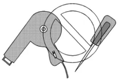
Technical line drawing of a mechanical device with a circular component and tool (no text or symbols)E. CLEANING
Cleaning the refrigerator is usually done after it is defrosted or put into storage. To clean the interior of the refrigerator, use lukewarm water and a mild dishwashing detergent. Use only warm water to clean the finned evaporator, gaskets, ice trays and shelves. NEVER use strong chemicals or abrasives to clean these parts as the protective surfaces will be damaged. It is important to always keep the refrigerator clean.
F. SHUTOFF (STORAGE PROCEDURE)
Place the toggle switches for DC and AC operation to the "OFF" position or turn the gas valve to position "OFF", as applicable. See FIG. 8.
When not in use, the refrigerator should be emptied, cleaned and dried and the door left open so that fresh air can circulate inside.
The travel latch placed in the second hole will hold the door ajar and allow air to circulate.
! CAUTION
DO NOT store explosive substances in the refrigerator, such as cigarette lighter gas, petrol, ether or the like.
SECTION D. MAINTENANCE & SERVICE TIPS FOR THE SERVICE TECHNICIAN
The user should be aware of service that must be done on a regular schedule to keep the refrigerator operating properly. The service should only be performed by a qualified technician who is familiar with LP gas systems and refrigerators.
1. REFRIGERATOR REMOVAL
Before working on, or removing the refrigerator, make sure the electrical supply (AC and DC) is turned OFF before leads are disconnected. Shut off the gas supply. Disconnect and cap the gas supply line. Loosen the screws anchoring the refrigerator to the enclosure and slide the refrigerator out of the compartment.
Replacement is the reverse of removal. Check all connections for gas leaks. Refer to Section A, Item 1 through 13 of Installation Instructions.
2. PERIODIC MAINTENANCE
To keep a Dometic refrigerator operating efficiently and safely, periodic inspection and cleaning of several components once or twice a year is recommended.
A. It is important to keep the area at the back of the refrigerator clean. Check the lower vent, upper vent and area between these openings for any obstructions such as bird/insect nests, spider webs, etc. Clean the coils on the back of the refrigerator. Use a soft brist led brush to dust off the coils..
NOTE: AVOID SPRAYING WATER THROUGH THE REFRIGERATOR VENTS WHEN WASHING THE RV.
It is important to keep the refrigerator vent area free from combustible material, gasoline and other flammable vapors or liquids.
B. Check all connections in the LP gas system (at the back of the refrigerator) for gas leaks. The LP gas supply must be turned on. Apply a noncorrosive bubble solution to all LP gas connections. The appearance of bubbles indicates a leak and should be repaired immediately by a qualified serviceman who is familiar with LP gas systems and refrigerators.
! WARNING
DO NOT USE A FLAME TO CHECK FOR GAS LEAKS.
C. Examination and Cleaning of Flue, Burner and Jet
Once or twice a year, look through the opening (see FIG. 9) in the burner box and examine the appearance of the burner flame which should be predominantly blue in color when the gas thermostat knob is set to its highest position. (Refer to FIG. 10).
If this is not the case, clean the flue, burner, jet, etc. (see section D and E).
FIG. 9
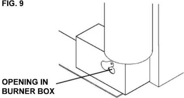
text_image
FIG. 9 OPENING IN BURNER BOXFIG. 10
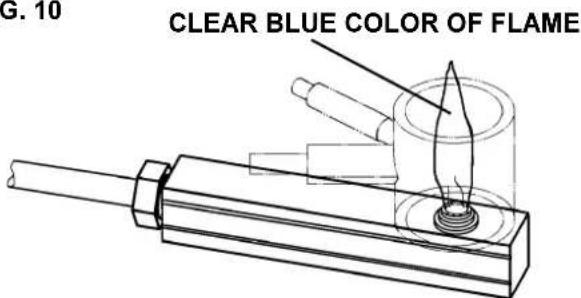
text_image
G. 10 CLEAR BLUE COLOR OF FLAMED. Cleaning of Burner, Burner Jet (Refer to FIG.11)
Proceed as follows:
1) Turn off the gas at the gas bottle.
2) By using a phillips screwdriver, remove the screw (B) and carefully withdraw the burner cover box. Clean the inside of the box of soot and other deposits.
3) To clean the burner, unscrew the screw (C) that fixes the burner on the boiler tube and be careful in order not to lose the washer.
4) Clean the inside of the burner.
5) To examine and eventually clean the burner jet, unscrew the gas pipe union (K) and pull out the burner jet (L).
6) Clean the jet by washing it in alcohol and blowing it through with air.
! CAUTION
DO NOT use a wire or pin when cleaning the burner jet as damage can occur to the precision opening. This can cause damage to the refrigerator or create a fire hazard.
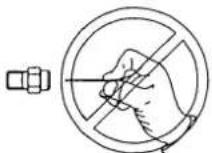
NOTE: The jet fitted to this refrigerator is a size "43" which is suitable for use on propane gas at 11 inches water column. The orifice in the jet is very small and must never be cleaned by means of a pin or similar instrument as this would damage the orifice. It must only be cleaned as described above.
7) Reassemble the components in the reverse order to that described above.
FIG. 11
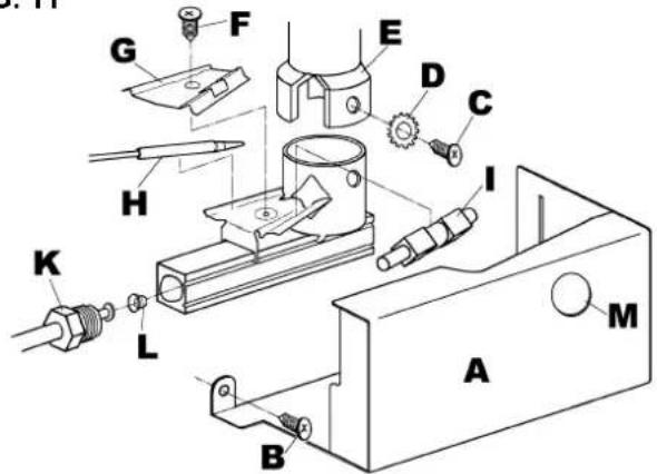
text_image
Technical diagram of a mechanical assembly with labeled parts A through M, showing exploded and assembled views.E. CLEANING OF FLUE TUBE, FLUE BAFFLE
Proceed as follows:
1) To clean the flue tube and the flue baffle, it is necessary to withdraw the refrigerator out of the recess. See Section D, Item 1.
2) By using a phillips screwdriver, remove the screw (B, in FIG. 11) and carefully withdraw the burner cover box.
3) Place a piece of paper or cloth between the boiler tube (E, in FIG. 11) and the burner assembly, to catch falling deposits.
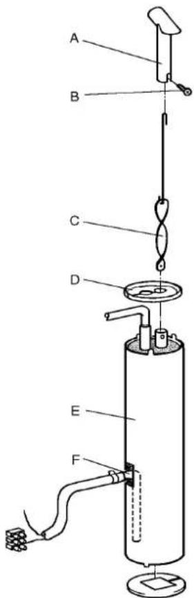
4) Remove the "T-piece" (A, in FIG. 12) at the top of the flue by unscrewing the screw (B, in FIG. 12) that fixes it to the flue pipe.
5) Carefully takeout the flue baffle (C, FIG. 12) and clean.
6) Clean the flue tube of soot, etc. with the aid of a special flue brush, available from your supplier.
FIG. 12
text_image
Labeled diagram of a laboratory apparatus with components A through F, showing internal components and connections.7) Reassemble the components in the reverse order to that described for removal, taking care to remake the gas connections soundly, and not forgetting to refit the flue baffle.
8) Reinstall the refrigerator in its recess. Connect the gas and electrical supplies, and check for gas leaks. Light the burner and check the appearance of the flame to ensure that it is predominantly blue (when the thermostat is at "HIGH"), then leave the refrigerator on "test" for at least an hour.
3. TROUBLESHOOTING
If the refrigerator fails to work, check the following points before calling a service technician:
A. Instructions for STARTING THE REFRIGERATOR, Section C, have been followed.
B. The refrigerator is level.
C. If it is possible to start the refrigerator on any of the connected sources of energy.
D. If the refrigerator fails to work on GAS, check:
1) That the gas bottle is not empty.
2) That all LP Gas valves in the supply line to the refrigerator are open.
NOTE: The following checks should be performed only by a qualified technician.
3) That sparks are generated by the piezo ignitor.
4) That the flame continues to burn after releasing the knob of the flame failure device (B, in FIG.8). If not, the thermocouple may be loose or defective.
E. If the refrigerator fails to work DC, check:
1) That the DC supply is connected to the refrigerator.
2) That the fuse on the DC supply is intact.
3) That the DC switch is set to the "ON" position (A, in FIG. 8).
F. If the refrigerator fails to work on AC, check:
1) That the AC supply is connected to the refrigerator.
2) That the fuse on the AC supply is intact.
3) That the AC switch is set to the "ON" position.
4) That the AC thermostat is not set to the "0" position.
G. If the refrigerator is not cold enough it may be because:
1) The ventilation is inadequate, because of reduced area of the ventilation passages (partial blockage of grilles from wire mesh, etc.).
2) The evaporator is frosted up.
3) The temperature control setting is incorrect.
4) The gas pressure is incorrect. Check the pressure regulator.
5) The ambient temperature is too high.
6) Too much warm food is loaded at one time.
7) The door is not properly closed or the magnetic sealing strip is defective.
All of the previous instructions are to be followed closely. This refrigerator is quality guaranteed; however, we are not responsible for any failures caused by improper adjustments and unfavorable installation conditions. If assistance is required, contact the service point or distributor service department.
DOMETIC
ÉTATS-UNIS
SERVICE OFFICE
The Dometic Corp.
509 So. Poplar St.
La Grange, IN 46761
Téléphone
(219) 463-4858
CANADA
Dometic Dist.
866 Langs Dr.
Cambridge, Ontario
Canada N3H 2N7
Téléphone :
(519) 653-4390
NUMÉRO DU SERVICE
D'ASSISTANCE À LA
CLIENTÈLE
800 544-4881

text_image
SP CERTIFIED
text_image
DESIGN SP CERTIFIED
natural_image
Line drawing of a rectangular box or enclosure with no text, numbers, or symbolsVEUILLEZ PRENDRE CETTE INFORMATION EN NOTE POUR RÉFÉRENCE ULTÉRIEURE
natural_image
Pure technical line drawing of a 3D cube with internal structure and directional arrows, no text or symbols present.B. FIXATION DU RÉFRIGÉRATEUR DANS L'ESPACE PRÉVU À CET EFFET
F = THERMOSTAT AU GAZ
G = BLOC TERMINAL EN C.C.
H = ENTRÉE DE GAZ