PROTIG 250 DC TRI - Welding machine GYS - Free user manual and instructions
Find the device manual for free PROTIG 250 DC TRI GYS in PDF.

User questions about PROTIG 250 DC TRI GYS
0 question about this device. Answer the ones you know or ask your own.
Ask a new question about this device
Download the instructions for your Welding machine in PDF format for free! Find your manual PROTIG 250 DC TRI - GYS and take your electronic device back in hand. On this page are published all the documents necessary for the use of your device. PROTIG 250 DC TRI by GYS.
USER MANUAL PROTIG 250 DC TRI GYS
natural_image
Line drawing of a portable electronic device with control knobs and buttons (no text or symbols)| FR | 02 / 03-17 / 110-116 |
| EN | 02 / 18-32 / 110-116 |
| DE | 02 / 33-48 / 110-116 |
| ES | 02 / 49-63 / 110-116 |
| RU | 02 / 64-79 / 110-116 |
| NL | 02 / 80-94 / 110-116 |
| IT | 02 / 95-109 / 110-116 |
PROTIG 250 DC TRI
Poste à souder TIG et MMA TIG (GTAW) and MMA (SMAW) welding machine Schweissgerät für WIG und E-Hand (MMA) Equipo de soldadura TIG y MMA Сварочный аппарат ТИГ и MMA TIG en MMA lasapparaat Dispositivo saldatura TIG e MMA
|
text_image
Technical diagram of an electronic device with labeled ports and connectors, showing internal components and connection points.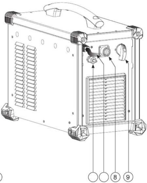
text_image
Technical diagram of a heat exchanger unit with labeled components and numbered parts||
text_image
250 A V s Hz % JOB In Out 6 7 5 I % I 10s F (Hz) 0s 20s 4 TIG - HF TIG - Lift MMA 2T 4T 4TL0G + Pulse Spot MMA Pulse 1 2 3AVERTISSEMENTS - RÈGLES DE SÉCURITÉ
CONSIGNE GÉNÉRALE
INSTALLATION – FONCTIONNEMENT PRODUIT
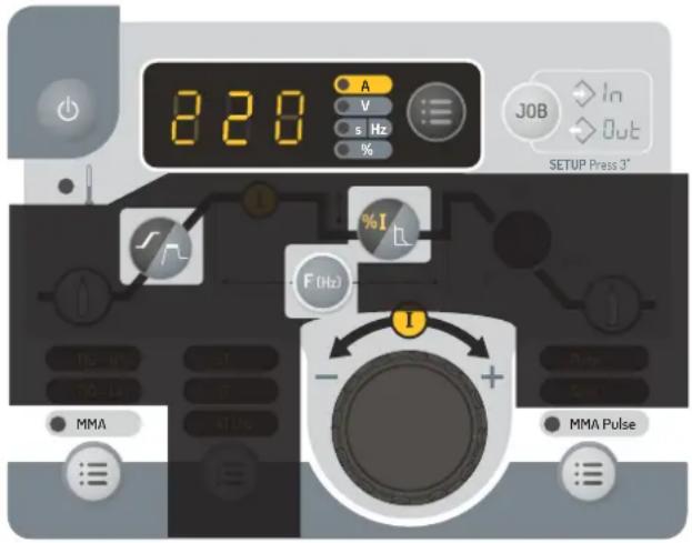
INTERFACE HOMME-MACHINE (IHM) (II)
text_image
820 A V s Hz % %I F (Hz) I TIG 10 TIG 14 AT ATUR MMA Pulse Spin MMA Pulse JOB In Out SETUP Prato 3"text_image
1 2 3 TIG HFtext_image
1 TIG LIFT 2 3text_image
850 A V s Hz % JOB In Out SETUP Press 3 10s 20s I I - + TIG - HF 2T TIG - Lift 4T 4T LOGtext_image
250 A V s Hz % JOB In Out SETUP Press 3 I % I 10s 20s F(Hz) - + TIG - HF 2T TIG - Lift 4T Pulsetext_image
250 A V s/Hz % JOB In Out SETUP: Press 3" F/Hz1 TIG - HF TIG - L/R 2T Spottext_image
Bouton principal T1 T2MODE 4T
flowchart
graph TD
    A["Bouton principal T1"] --> B["Step 1"]
    B --> C["t"]
    C --> D["T2"]
    D --> E["Step 2"]
    E --> F["t"]
    F --> G["T3"]
    G --> H["Step 3"]
    H --> I["T4"]
    style A fill:#f9f,stroke:#333
    style B fill:#ccf,stroke:#333
    style C fill:#cfc,stroke:#333
    style D fill:#fcc,stroke:#333
    style E fill:#cff,stroke:#333
    style F fill:#ffc,stroke:#333
    style G fill:#cfc,stroke:#333
    style H fill:#fcc,stroke:#333
    style I fill:#ffc,stroke:#333
MODE 4T log
text_image
Bouton principal ou Bouton secondaire T1 T2 T3 T4 <0.5s <0.5s >0.5sMESSAGES D'ERREUR, ANOMALIES, CAUSES, REMÈDES
CONDITIONS DE GARANTIE
Read and understand the following safety instructions before use.
Any modification or updates that are not specified in the instruction's manual should not be undertaken.
The manufacturer is not liable for any injury or damage caused due to non-compliance with the instructions featured in this manual. If there is any issue or if you are unsure, please ask a qualified person to handle the installation.
ENVIRONMENT
This equipment must only be used for welding operations in accordance with the limits indicated on the descriptive panel and/or in the user manual. Safety instructions must be followed. In case of improper or unsafe use, the manufacturer cannot be held liable.
This equipment must be used and stored in a room free from dust, acid, flammable gas or any other corrosive agent. The same rules apply for storage. Operate the machine in an open, well-ventilated area.
Temperature range:
Use between -10 and +40°C (+14 and +104°F).
Storage between -20 and +55°C (-4 and 131°F).
Air humidity:
Lower or equal to 50% at 40°C (104°F).
Lower or equal to 90% at 20°C (68°F).
Altitude:
Up to 1000 meters above sea level (3280 feet).
INDIVIDUAL PROTECTION & OTHERS
Arc welding can be dangerous and can cause serious injury or even death.
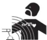
Welding exposes the user to dangerous heat, arc rays, electromagnetic fields, risk of electric shock, noise and gas fumes. People wearing pacemakers are advised to consult a doctor before using the welding machine.
To protect oneself as well as others, ensure the following safety precautions are taken:

In order to protect you from burns and radiations, wear clothing without turn-up or cuffs. These clothes must be insulating, dry, fireproof, in good condition and cover the whole body.

Wear protective gloves which guarantee electrical and thermal insulation.

Use sufficient welding protective gear for the whole body: hood, gloves, jacket, trousers... (varies depending on the application/operation). Protect the eyes during cleaning operations. Contact lenses are prohibited during use.
It may be necessary to install fireproof welding curtains to protect the area against arc rays, weld spatter and sparks. Inform the people around the working area to never look at the arc nor the molten metal, and to wear protective clothes.

Ensure ear protection is worn by the operator if the work exceeds the authorised noise limit (the same applies to any person in the welding area).
Keep hands, hair and clothes away from moving parts such as fans, and engines.
Never remove the safety covers from the cooling unit when the machine is plugged in. The manufacturer is not liable for any injury or damage due to non-compliance with the safety precautions.
Parts that have just been welded will be hot and may cause burns when touched. During maintenance work on the torch or the electrode holder, you should make sure that temperature is cold enough and wait at least 10 minutes before any intervention. When using a water-cooled torch, make sure that the cooling unit is switched on to avoid any burns that could potentially be caused by the liquid.
It is important to secure the working area before leaving it to ensure protection of the goods and the safety of people.
WELDING FUMES AND GAS

Fumes, gas and dust produced during welding are hazardous to health. It is mandatory to ensure adequate ventilation and/or extraction to keep fumes and gas away from the work area. Using an air fed welding helmet is recommended in case of insufficient ventilation in the workplace.
Check that the air supply is suitable by referring to the recommended safety regulations.
Precautions must be taken when welding in small areas, and the operator will need supervision from a safe distance. Welding specific pieces of metal containing lead, cadmium, zinc, mercury or beryllium can be extremely toxic. The user will also need to remove the grease from the workpiece before welding.
Gas cylinders must be stored in an open or ventilated area. They must be stored vertically and held by a support or trolley to limit the risk of fall. Do not weld in areas where grease or paint are stored.
FIRE AND EXPLOSION RISKS

Protect the entire welding area. Flammable materials must be moved to a minimum safe distance of 11 meters. A fire extinguisher must be readily available near the welding operations.
Be careful of spatter and sparks, even through cracks. If not careful then this could potentially lead to a fire or an explosion.
Keep people, flammable materials/objects and containers that are under pressure at a safe distance.
Welding in closed containers or pipes should be avoided and, if they are opened, they must be emptied of any flammable or explosive material (oil, fuel, gas ...).
Grinding operations should not be carried out close to the power supply or any flammable materials.
GAS CYLINERS
Gas leaking from the cylinders can lead to suffocation if present in high concentration around the work area (ventilation required). Transport must be done safely: cylinders closed and the welding current source switched off. They must be stored vertically and held by a support to limit the risk of falling.
Close the cylinder between two uses. Beware of temperature variations and sun exposure.
The cylinder must not be in contact with a flame, electric arc, torch, earth clamp or all other sources of heat.
Always keep gas cylinders away from electrical circuits, and therefore never weld a cylinder under pressure.
Be careful when opening the valve on the gas bottle, it is necessary to remove the tip of the valve and to ensure that the gas meets your welding requirements.
ELECTRICAL SAFETY

The electrical mains used must have an earth terminal. Use the recommended fuse size. An electric shock could cause serious injuries or potentially even deadly accidents.
Do not touch any live part of the machine (inside or outside) when it is plugged in (Torches, earth cable, cables, electrodes) because they are connected to the welding circuit.
Before opening the device, it is imperative to disconnect it from the mains and wait 2 minutes, so that all the capacitors are discharged.
Do not touch the torch or electrode holder and the earth clamp at the same time.
Damaged cables and torches must be changed by a qualified technician. Make sure that the cable cross section is adequate with the usage (extensions and welding cables). Always wear dry clothes which are in good condition in order to be isolated from the welding circuit. Wear insulating shoes, regardless of the workplace/environment in which you work in.
EMC CLASSIFICATION

This Class A machine is not intended to be used on a residential site where the electric current is supplied by the domestic low-voltage power grid. There may be potential difficulties in ensuring electromagnetic compatibility at these sites, due to conducted interferences as well as radiation.
This equipment complies with the IEC 61000-3-11 standard.
This equipment does not comply with IEC 61000-3-12 and is intended to be connected to private low-voltage systems interfacing with the public supply only at the medium- or high-voltage level. On a public low-voltage power grid, it is the responsibility of the installer or user of the device to ensure, by checking with the operator of the distribution network, which device can be connected.
ELECTROMAGNETIC INTERFERENCES
The electric current flowing through any conductor causes electrical and magnetic fields (EMF). The welding current generates an EMF around the welding circuit and the welding equipment.
The EMF electromagnetic fields can interfere with certain medical implants, such as pacemakers. Protective measures must be taken for people having medical implants. For example, by restricting access to passers-by or conducting an individual risk evaluation for the welders.
All welders should use the following procedures to minimise exposure to electromagnetic fields from the welding circuit:
- position the welding cables together - secure them with a clamp, if possible;
- position your torso and head as far as possible from the welding circuit
- never wrap the cables around the body.
-
do not position the body between the welding cables. Hold both welding cables on the same side of the body;
-
connect the earth clamp as close as possible to the area being cut;
- do not work next to the welding power source, do not sit or lean on it.
- do not weld when transporting the welding current source or the wire feeder.
People wearing pacemakers are advised to consult their doctor before using this device.
Exposure to electromagnetic fields while welding may have other health effects which are not yet identified.
RECOMMENDATIONS FOR EVALUATING THE WELDING AREA AND INSTALLATION
General points
The user is responsible for the installation and use of the arc welding equipment according to the manufacturer's instructions. If electromagnetic disturbances are detected, the user is responsible for resolving the situation with the manufacturer's technical assistance. In some cases, this corrective action may be as simple as earthing the welding circuit. In other cases, it may be necessary to build an electromagnetic shield around the welding power source and around the entire piece by fitting input filters. In all cases, electromagnetic interferences must be reduced until they are no longer an issue.
Welding area assessment
Before installing the machine, the user must evaluate the possible electromagnetic problems that may arise in the area where the installation is planned. The following should be taken into account:
a) the presence (above, below and next to the arc welding machine) of other power cables, remote cables and telephone cables;
b) Radio/TV transmitters and receptors;
c) computers and other control equipment;
d) safety-critical equipment, e.g. protection of industrial equipment;
e) the health of neighbouring persons, e.g. use of pacemakers or hearing aids;
f) the equipment used for calibration or measurement;
g) the immunity of other materials in the environment.
The operator has to ensure that the devices and equipment used in the same area are compatible with each other. This may require additional protective measures;
h) the time of day during the welding or other activities have to be performed.
The dimension of the cutting area that has to be considered depends on the size and shape of the building and the type of work undertaken. The area taken into consideration might go beyond the limits of the installations.
Welding area assessment
Besides the welding area assessment, the assessment of the arc welding systems installation itself can be used to identify and resolve cases of disturbances. The assessment of emissions must include in situ measurements as specified in Article 10 of CISPR 11. In situ measurements can also be used to confirm the effectiveness of mitigation measures.
RECOMMENDATION ON METHODS OF ELECTROMAGNETIC EMISSIONS REDUCTION
a. National power grid: The arc welding machine must be connected to the national power grid in accordance with the manufacturer's recommendation. In case of interferences, it may be necessary to take additional precautions such as the filtering of the power supply network. Consideration should be given to shielding the power supply cable in a metal conduit or equivalent of permanently installed arc welding equipment. It is necessary to ensure the electrical continuity of the frame along its entire length. The shielding should be connected to the welding current source to ensure a good electrical contact between the conduit and the casing of the welding current source.
b. Maintenance of arc welding equipment: The arc welding machine should be subject to a routine maintenance check according to the recommendations of the manufacturer. All accesses, service doors and covers should be closed and properly locked when the arc welding equipment is on. The arc welding equipment must not be modified in any way, except for the changes and settings outlined in the manufacturer's instructions. The spark gap of the arc starts and arc stabilization devices must be adjusted and maintained according to manufacturer's recommendations.c.
c. Welding cables: Welding cables: Cables must be as short as possible, close to each other and close to the ground, if not on the ground.
d. Equipotential bonding: Consideration should be given to bond all metal objects in the surrounding area. However, metal objects connected to the workpiece increase the risk of electric shock if the operator touches both these metal elements and the electrode. It is necessary to insulate the operator from such metal objects.
e. Earthing of the welded part: When the part is not earthed - due to electrical safety reasons or because of its size and its location (which is the case with ship hulls or metallic building structures), the earthing of the part can, in some cases but not systematically, reduce emissions It is preferable to avoid the earthing of parts that could increase the risk of injury to the users or damage other electrical equipment. If necessary, it is appropriate that the earthing of the part is done directly, but in some countries that do not allow such a direct connection, it is appropriate that the connection is made with a capacitor selected according to national regulations.f.
f. Protection and shielding: The selective protection and shielding of other cables and devices in the area can reduce perturbation issues. The protection of the entire welding area can be considered for specific situations.
TRANSPORT AND TRANSIT OF THE WELDING MACHINE

The machine is equipped with a handle to easy transportation. Be careful not to underestimate the weight of the machine. The handle cannot be used to hang or attach the machine on something else.
Do not use the cables or torch to move the machine. The welding equipment must be moved in an upright position.
Never lift the machine while there is a gas cylinder on the support shelf. The transport rules applying to each item are different.
Do not place/carry the unit over people or objects.
EQUIPMENT INSTALLATION
- Place the machine on the floor (maximum slope of 10^ ).
- Provide an adequate area to ventilate the machine and access the controls.
• This equipment must be used and stored in a place protected from dust, acid, gas or any other corrosive substance. - The machine must be placed in a sheltered area away from rain or direct sunlight.
• The machine protection level is IP23, which means : - Protection against access to dangerous parts from solid bodies of a ≥12.5mm diameter and,
- Protection against the rain inclined at 60° towards the vertical.
These devices can be used outside in accordance with the IP23 protection index.
Power cables, extension leads and welding cables must be fully uncoiled to prevent overheating.

The manufacturer does not accept any liability in relation to damages caused to objects or harm caused to persons as the result of incorrect and/or dangerous use of the machine.
MAINTENANCE / RECOMMENDATIONS


- Maintenance should only be carried out by a qualified person. A yearly maintenance is recommended.
- Ensure the machine is unplugged from the mains, and then wait 2 minutes before carrying out maintenance work. Inside, voltages and currents are high and dangerous.
- Remove the casing regularly and any excess of dust. Take this opportunity to have the electrical connections checked by a qualified person, with an insulated tool.
- Regularly check the condition of the power supply cable. If the power cable is damaged, it must be replaced by the manufacturer, its after sales service or an equally qualified person to prevent danger.
- Ensure the vents of the device are not blocked to allow adequate air circulation.
- Do not use this equipment to thaw pipes, to charge batteries, or to start any engine.
INSTALLATION – PRODUCT OPERATION
Only qualified personnel authorised by the manufacturer should perform the installation of the welding equipment. During the installation, the operator must ensure that the machine is disconnected from the mains. Connecting generators in series or in parallel is forbidden. It is recommended to use the welding cables supplied with the unit in order to obtain the optimum product settings.
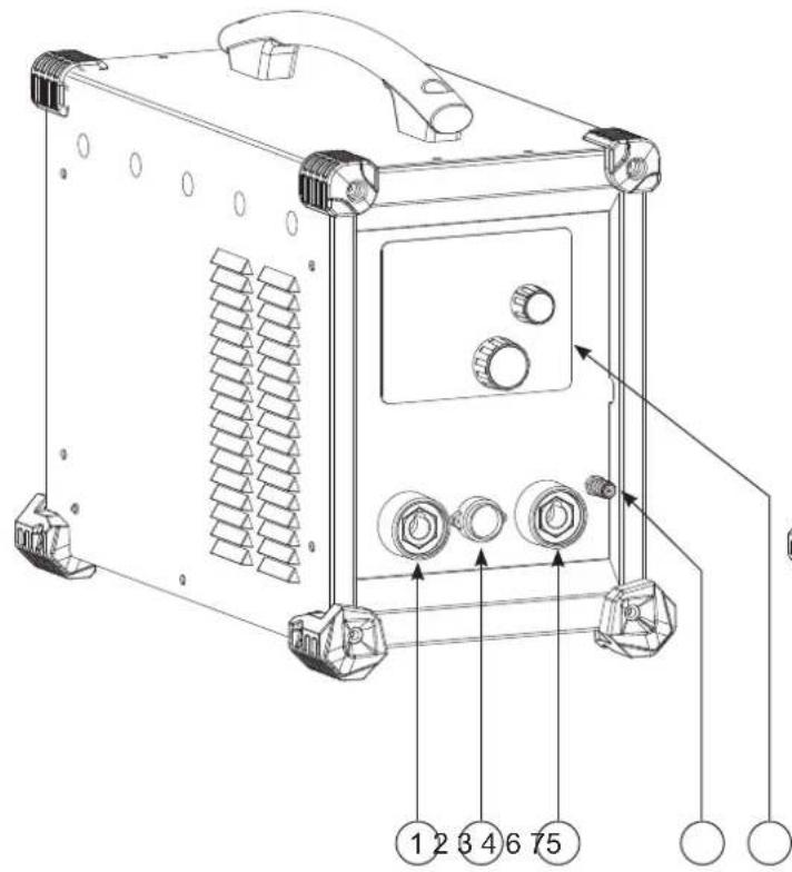
EQUIPMENT DESCRIPTION (I)
This welding machine is an inverter welding unit designed for use on refractory electrodes (TIG) in direct current (DC) and electrode welding (MMA). TIG welding requires gas shield protection of pure gas (Argon).
The MMA process can be used to weld any type of electrodes: rutile, basic, stainless steel and cast iron.
1- Positive polarity plug 6- Gas inlet
2- Trigger connection 7- Power supply cable (3 m)
3- Polarity plug 8- Remote control cable connector
4- Gas connection for torch 9- ON / OFF switch
5- Keyboard + buttons
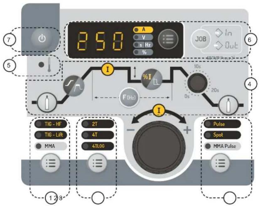
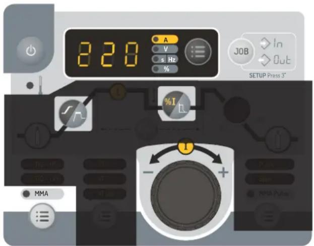
INTERFACE (MMI) (II)
1- Process section 5- Thermal protection indicator
2- Trigger selection mode 6- Display and options
3- Process options selection 7- Sleep button
4- Welding parameters settings.
POWER SWITCH
- This machine is fitted with a 16 A socket type EN 60309-1 which must be connected to a three-phase 400V (50 - 60 Hz) power supply fitted with four wires and one earthed neutral. The absorbed effective current (I1eff) is indicated on the machine, for optimal use. Check that the power supply and protection (fuse and/or circuit breaker) are compatible with the current required by the machine. In some countries, it may be necessary to change the plug to allow the use at maximum settings.
- This machine is started up by turning the on/off switch to position I. Conversely, to turn the machine off, turn the switch back to position O.
- This machine will enter a protection mode if the supply voltage is higher or lower than 15% of the specified voltage(s) (a fault code will appear on the keypad display). Normal operation resumes as soon as the supply voltage returns to its nominal range.
• Fan behaviour: In MMA mode, the fan works continuously. In TIG mode, the fan works only when welding, then stops after cooling. - The arc priming and stabilisation device is designed for manual and mechanically guided operation.
CONNECTION TO A GENERATOR
This equipment may operate with generators provided that the auxiliary power meets the following requirements:
- The voltage must be alternating, adjusted as specified and with a peak voltage of less than 700 V,
- The frequency must be between 50 and 60 Hz.
It is imperative to check these requirements as many generators generate high voltage peaks that can damage the machine.
USE OF EXTENSION LEADS
All extension cables must have an adequate size and section, relative to the machine's voltage. Use an extension lead that complies with national safety regulations.
| Voltage input | Length and thickness of the extension lead | |
| <45 m <100 m | ||
| 400 V 2.5 mm ^2 | ||
GAS CONNECTION
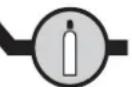
This equipment is equipped with two connections. A cylinder connector for the gas inlet into the station, and a torch gas connector for the gas outlet at the end of the torch. We recommend that you use the adaptors supplied with your set to ensure an optimal connection.
RESETTING THE WELDING STATION
It is possible to restore the factory settings of the welding machine. When the product is in sleep mode, press the sleep exit push button (II-7) for 3 seconds. The product then displays «3», «2», «1» and then resets the unit.
FUNCTION, MENU AND PICTOGRAM DESCRIPTIONS
| FUNCTION PICTOGRAM | TIG DC | MMA | Comments | |
| HF ignition TIG process with | HF ignition HF | ✓ | ||
| Lift ignition TIG process with | LIFT ignition lift | ✓ | ||
Pre-gas Time to purge the torch and  | act the area with gas before ignition | |||
Up slope current Up slope current  | ✓ | |||
| Welding current Second welding current | ✓ | |||
| Cold current/Background current) |  | ✓ | Second welding current or «cold» current in standard 4TLOG or in PULSE mode | |
| PULSE frequency PULSATION | ON frec  of the PULSE mode (Hz) of the PULSE mode (Hz) | |||
| Down slope current. | 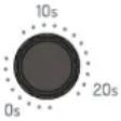 | ✓ | Downslope current to minimum current, I Stop (S) to prevent weld defects and craters. | |
| Post-gas |  | ✓ | Duration for which gas is released after the arc has stopped. It protects the weld pool and the electrode against oxidization when the metal is cooling (S). | |
HotStart Adjustable overcurrent at t  | ning of the welding (%) | |||
| ArcForce |  | ✓ | Overcurrent delivered to avoid sticking when the electrode enters the welding pool | |
| TIG PULSE Pulse mode | Pulse | ✓ | ||
| TIG SPOT Spot Mode | Spot | ✓ | ||
| TIG SPOT PULSE | Spot & Pulse | ✓ | Pulse spot Mode | |
| MMA PULSE MMA process | in PULSE PMode | ✓ | ||
| 2T | 2T | ✓ | 2 time torch mode | |
| 4T | 4T | ✓ | 4 time torch mode | |
| 4T LOG | 4T LOG | ✓ | 4 time LOG torch mode | |
| Ampere (unit) | A | ✓ | ✓ | Amperes unit for welding current settings |
| Volt (unit) | V | ✓ | ✓ | Volt unit for displaying welding voltage |
| Second or Hertz (units) | s | Hz | ✓ | ✓ | Seconds or Hertz unit for time or frequency settings |
| Percentage (unit) | % | ✓ | ✓ | Percentages unit for proportionate settings |
Display switch A or V Switches the  of voltage of current during and after welding of voltage of current during and after welding | ||||
Program menu access Access to c  tion menu (SAVE, JOB, ...) tion menu (SAVE, JOB, ...) | ||||
Thermal protection Standard symbol  cate the thermal protection state cate the thermal protection state | ||||
| Sleep mode Sleep mode |  | √ | √ | |
HMI OPERATION AND DESCRIPTION OF ITS BUTTONS
 | Sleep Mode / Sleep ExitThis key is used to activate or exit the standby mode. Activation of the mode is not possible when the product is in welding condition.Note: When the power is turned on, the product starts in standby mode. |
    | Welding process selection buttonThis button is used to select the welding process. Each successive press/release switches between the following welding processes: TIG HF / TIG LIFT / MMA. The LED indicates the selected process. |
    | Trigger mode selection buttonThis button is used to set the trigger operation mode of the lamp. Each successive press toggles between the following modes: 2T / 4T / 4T LOG The LED indicates the selected mode.Note: the trigger mode selected by default at machine startup corresponds to the last trigger mode used before the last sleep or shutdown. For more information, refer to the section «Compatible Torches and Trigger Behaviour». |
    | Process options selection buttonThis key allows the selection of the «Sub-process». Each successive press toggles between the following modes: PULSE / SPOT / SPOT-PULSE (only in TIG mode) / MMA PULSE (only in MMA mode). The LED indicates the selected process.Note: SPOT mode is not accessible in 4T & 4T Log trigger configuration and in MMA PULSE welding mode.MMA PULSE welding mode is not accessible in 4T & 4T LOG trigger configurationNote: the sub-process selected by default at machine startup corresponds to the last sub-process used before the last sleep or shutdown. |
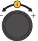 | Main incremental encoderBy default, the incremental encoder allows the setting of the welding current. It is also used to set the values of other parameters which are then selected via the associated keys. Once the setting is set, it is possible to press the key of the setting that has just been set again so that the incremental encoder is again linked to the current setting. It is also possible to press another key related to another parameter to adjust it. If no action is performed on the HMI for 5 seconds, the incremental encoder is again linked to the welding current setting. |
 | « Pre-Gas « buttonThe Pre-Gas adjustment is done by pressing and releasing the Pre-Gas button and then activating the main incremental encoder. Pre-Gas value increases when the incremental encoder is operated clockwise and decreases when it is operated anti-clockwise. Once the setting has been set, it is possible to press and release the Pre-Gas button again to re-link the main incremental encoder to the current setting or to wait for 5 seconds. The setting step is 0.1 sec. The minimum value is 0 sec. and the maximum value is 20 sec. |
 | « Post gas « buttonThe Pre-Gas adjustment is done by pressing and releasing the Pre-Gas button and then activating the main incremental encoder. Post-Gas value increases when the incremental encoder is operated clockwise and decreases when it is operated anti-clockwise. Once the setting is set, it is possible to press and release again the Pre-gas button to re-link the main incremental encoder to the current setting or to wait 5 seconds. The setting step is 0.1 sec. The minimum value is 0 sec. and the maximum value is 20 sec. The default value is 3 sec. |
 | «UpSlope» current adjustment button.The current ramp is set by pressing and releasing the current ramp button and then operating the main incremental encoder. Current ramp-up value increases when the incremental encoder is operated clockwise and decreases when it is operated anti-clockwise. Once the setting has been set, it is possible to press and release the current ramp-up button again to re-link the main incremental encoder to the current setting or to wait for 5 seconds. The setting step is 0.1 sec. The minimum value is 0 sec. and the maximum value is 20 sec. The default value is 0sec. In MMA mode, the Hotstart is adjustable between 0 and 100% of the welding current in 1% steps. The default value is 40%. |
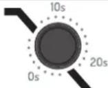 | DownSlope adjustment potentiometerThe «DownSlope» potentiometer is used to adjust the current fade value (clockwise increment and counterclockwise decrement). The value is visible on the 7-segment display and remains displayed for 5 seconds if an action on the potentiometer is performed. The minimum value is 0 sec. and the maximum value is 20 sec. |
 | Cold current adjustment buttonWhen one of the 2 processes «HF TIG» or «LIFT TIG» is selected, the cold current setting button is used to adjust the value of the cold current (only in «4T LOG» or «PULSE»). The value can be adjusted between 20% and 80% of the welding current. The incremental step is 1%. The default value is 50%.In MMA mode, the Arc Force is indexed from 0 to 80% (0= no Arc Force / 1 to 80% = Arc Force setting possible).The default index value is 40%. |
WELDING WITH RUBBERED ELECTRODE (MMA MODE)
CONNECTIONS AND RECOMMENDATIONS
- Connect the electrode holder and earth clamp to the corresponding sockets.
- Ensure that the welding polarities and intensities indicated on the electrode packaging are observed.
- Remove the electrode from the electrode holder when the machine is not in use.
CHOICE OF COATED ELECTRODES
- Rutile electrode: very easy to use in all positions with DC current
- Basic electrode: used in all CC positions, it is suitable for safety work due to its increased mechanical properties.
MMA STANDARD
This standard MMA welding mode is suitable for most applications. It allows welding with all types of coated electrodes, rutile, basic and on all materials: steel, stainless steel and cast iron.
text_image
220 A V s Hz % %I Tg - N TQ - U MMA SETUP Press 3"MMA Standard
The grey areas are not useful for this mode.
| Designation Setting Description & advice | |
| Percentage of Hot Start 0 - 100 % | The Hot Start is an overcurrent during priming to prevent the wire from sticking to the part to be welded. It is set in Intensity and Time. |
| Welding current 10 - 220 A | |
| Arc Force 0 - 80 % |
Pulse MMA
This MMA Pulse welding mode is suitable for applications in the vertical up position (PF). The pulse mode keeps the weld pool cold and eases the transfer of matter. Without the pulse mode, vertical-up welding requires a difficult «Christmas tree» shape triangular movement. With the MMA Pulsed mode, this movement is no longer required and a simple straight up movement is enough (depending on the thickness of the workpiece). If you wish to widen your weld pool, a simple lateral movement is enough (similar to standard welding). This process allows greater control during vertical-up welding.
The pulse frequency is adjusted by pressing and releasing the «F(Hz)» button and then activating the main incremental encoder. Frequency value increases when the incremental encoder is operated clockwise and decreases when it is operated anti-clockwise. Once the setting is set, it is possible to press and release again the «F(Hz)» button to re-link the main incremental encoder to the current setting or to wait 2 seconds.
text_image
820 A V s Hz % %I F (Hz) MMA AT/Hz TJ-141 TJ-141 AT/Hz TJ-141 TJ-141 TJ-141 TJ-141 TJ-141 TJ-141 TJ-141 TJ-141 TJ-141 TJ-141 TJ-141 TJ-141 TJ-141 TJ-141 TJ-141 MMA Pulse IN Out SETUP Press 3"MMA PULSE
The grey areas are not useful for this mode.
| Designation Setting Description & advice | ||
| Percentage of Hot Start 0 - 100 % | The Hot Start is an overcurrent during priming to prevent the wire from sticking to the part to be welded. It is set in Intensity and Time. | |
| Welding current 10 - 220 A | The welding current is adjusted according to the type of electrode chosen (refer to the electrode packaging). | |
| Pulse frequency 1 - 20 Hz | Pulsation frequency of the PULSE mode.The incrementation step depends on the frequency range: | |
| Pulse frequency Incremental step | ||
| 1 Hz - 20 Hz 0.1 Hz | ||
| Arc Force 0 - 80 % | The Arc Force is an overcurrent delivered when the electrode or drop comes into contact with the solder bath in order to avoid sticking. | |
MMA - Advanced menu
Additional settings can be accessed in the advanced menu.
These advanced settings are accessed by pressing button «JOB» for more than 3 seconds. The rotation of the main incremental encoder allows access to the following advanced settings:
| Parameter | Description | Setting | Standard | Pulse | Recommendations |
| « ASt » | AntiSticking | ON/OFF | √ | √ | The anti-sticking feature is recommended to safely remove the electrode in case it is stuck to the metal. |
| « HSt » | HotStart duration | 0 - 2 s | √ | √ | The duration of the HotStart can be adjusted to make the arcing easier when using difficult electrodes. |
| « dcy » | Duty Cycle | 20 % - 80 % | √ | Time balance of the hot current (I) of the pulsation | |
| « Ico » | Cold current/Background current) | 20 % - 80 % | √ | Second welding current known as «cold» welding current |
The parameter to be modified is validated by pressing the button «JOB». The advanced settings menu can be exited with «ESC».
TUNGSTEN ELECTRODE WELDING WITH INERT GAS (TIG MODE)
CONNECTIONS AND RECOMMENDATIONS
• The TIG DC welding requires gas shield protection of pure gas (Argon).
- Connect the earth clamp to the positive connector (+). Connect the power cable to the negative plug (−), as well as the torch and the gas connections.
- Ensure that the torch is equipped and ready to weld, and that the consumables (Vice grip, ceramic gas nozzle, collet and collet body) are not da-
maged.
- The electrode choice depends on the TIG DC process current.
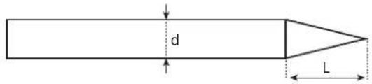
ELECTRODE GRINDING
For optimal operation, it is recommended to use a sharpened electrode as follows:
text_image
d LL = 3 x d for a low current.
L = d for a high current
CHOICE OF ELECTRODE DIAMETER.
| Electrode ∅ (mm) | TIG DC | |
| Pure tungsten Tungsten with oxides | ||
| 1 10 > 75 10 | >75 | |
| 1.6 60 > 150 | 60 > 150 | |
| 2 75 > 180 | 100 > 200 | |
| 2.5 130 > 230 | 170 > 250 | |
| 3.2 160 > 310 | 225 > 330 | |
| Environ = 80 A per mm ∅ | ||
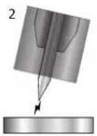
SELECT IGNITION MODE
TIG HF High Frequency start without contact.
TIG Lift contact ignition (for environments sensitive to HF disturbances).
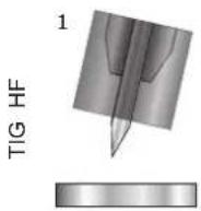
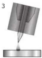
1- Place the torch in the welding position above the part (distance of about 2-3 mm between the electrode tip and the part).
2- Press the torch trigger (the arc starts without contact using High Frequency impulses).
3- The initial welding current circulates, the welding carries on according to the welding cycle.
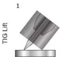
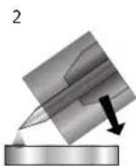
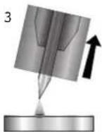
1- Position the torch nozzle and electrode tip on the part and press the torch button.
2- Tilt the torch until a distance of about 2-3 mm separates the tip of the electrode from the part. The arc starts.
3- Put the position back into position to start the welding cycle.
Warning: Increasing the length of the torch or earth return cables beyond the maximum length specified by the manufacturer will increase the risk of electric shock.
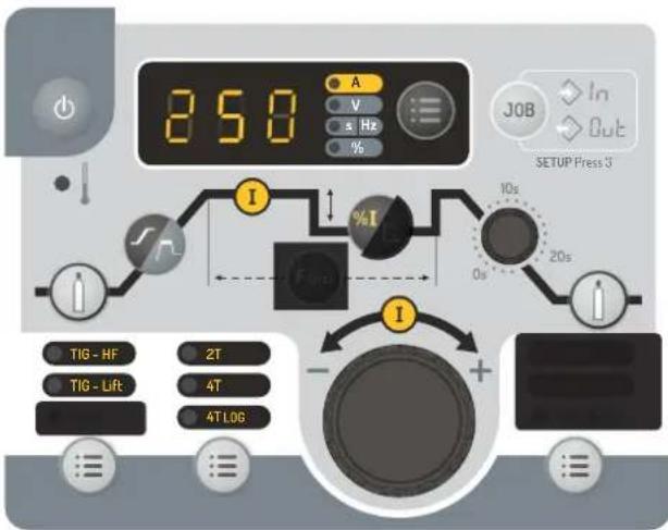
TIG DC - STANDARD
- StandardThe TIG DC Standard welding process allows high quality welding on most ferrous materials such as steel, stainless steel, but also copper and its alloys, titanium. The many possibilities of current and gas management allow you to perfectly control your welding operation, from priming to final cooling of your welding rod.
text_image
250 A V s Hz % JOB In Out SETUP Press 3 I % I 10s 20s TIG - HF 2T TIG - Lift 4T 4T LOG I - + -TIG DC Standard
The grey areas are not useful for this mode.
TIG DC - Pulse
This pulsed current welding mode is a combination of high current pulses (I, welding pulse) and low current pulses (I_Cold, part cooling pulse). This pulse mode allows to assemble pieces while keeping the machine cool.
Example :
The welding current I is set to a 100A and % (I_cold) = 50%, thus a Cold current of = 50% x 100A = 50A. F(Hz) is set to 2 Hz, the signal period will be 1/2Hz = 500 ms. Every 250ms, a 100A pulse then a 50A pulse will succeed each other.
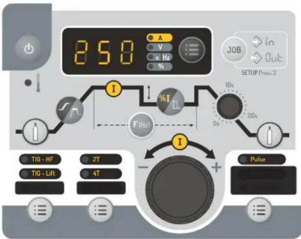
text_image
250 A V s Hz % JOB In Out SETUP Press 3 I % I 10s 20s F(Hz) - + TIG - HF 2T TIG - Lift 4T PulsePulse TIG DC
The grey areas are not useful for this mode.
Recommendations:
Choice of frequency:
- If welding with manual filler metal, then F(Hz) synchronised to the filler metal action,
- If thin without filler (< 0.8 mm), F(Hz) >> 10Hz
The pulse frequency is adjusted by pressing and releasing the «F(Hz)» button and then activating the main incremental encoder. Frequency value increases when the incremental encoder is operated clockwise and decreases when it is operated anti-clockwise. Once the setting is set, it is possible to press and release again the «F(Hz)» button to re-link the main incremental encoder to the current setting or to wait 2 seconds.
| Designation Setting Description & advice | ||
| Pre-gas 0 - 20 s Time to purge the torch and to protect the area with gas before ignition | ||
| Rising current 0 - 20 s Current rise ramp. | ||
| Welding current 5 - 250 A Welding current | ||
| Cold current/Background current) | 20 - 80 % | Second welding current known as «cold» welding current |
| Pulse frequency 0.1 - 900 Hz Pulse frequency | ||
| Evacuation 0 - 20 s Down slope current. | ||
| Post-gas 0 - 20 s | Duration for which gas is released after the arc has stopped. It protects the weld pool and the electrode against oxidisation when the metal is cooling down. | |
TIG - Advanced menu
Additional settings can be accessed in the advanced menu.
These advanced settings are accessed by pressing button «≡» for more than 3 seconds. The rotation of the main incremental encoder allows access to the following advanced settings:
| Parameter | Description Setting Standard | Pulse Recommendations | |||
| « ISa » | Current threshold when starting the weld. | 10 % - 200 % | √ | √ | This current threshold is a phase before the current upslope. |
| « tSa » | Time threshold when starting the weld. | 0 s - 10 s | √ | √ | |
| « ISo » | Current threshold when the weld stops. | 10 % - 100 % | √ | √ | This current threshold is a phase before the current upslope. |
| « tSo » | Time threshold when the weld stops. | 0 s - 10 s | √ | √ |
The parameter to be modified is validated by pressing the button « ≡ ». The advanced settings menu can be exited with «ESC».
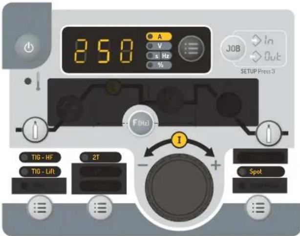
SPOT welding
This welding mode allows the pre-assembly of parts before welding. Scoring can be manual by trigger or delayed with a predefined scoring delay. This spot timer allows for a better reproducibility and the realisation of non-oxidized spots (accessible with the «F(Hz)» button).
text_image
850 A V s Hz % JOB In Out SETUP Press 3 F(Hz) I TIG - HF 2T TIG - Lift SpotTIG SPOT
The grey areas are not useful for this mode.
| Description Setting Recommendations | ||
| Pre-gas 0 - 20 s | Time to purge the torch and to protect the area with gas before ignition | |
| Welding current | 10 - 250 A | Welding current |
| Spot | Man, 0,1 - 25 s Manual or a defined time. | |
| Post-gas | 0 - 20 s | Duration for which gas is released after the arc has stopped. It protects the weld pool and the electrode against oxidisation when the metal is cooling down. |
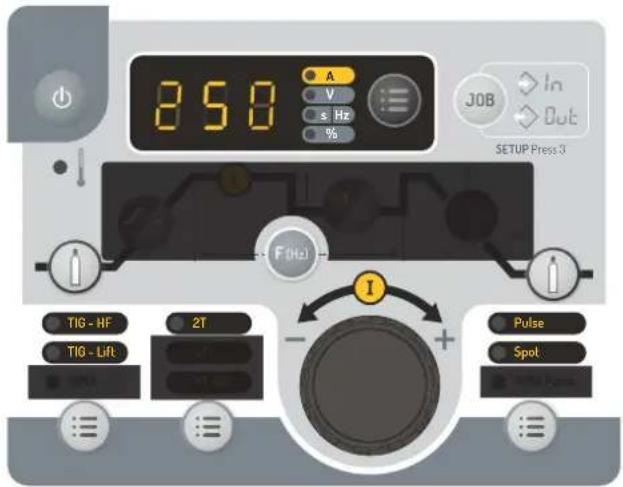
SPOT PULSE welding
This welding mode on thin sheet metal allows the pre-assembly of parts before welding. Scoring can be manual by trigger or delayed with a predefined scoring delay. This spot timer allows for a better reproducibility and the realisation of non-oxidized spots (accessible with the «F(Hz)» button).
text_image
250 A V s Hz % JOB In Out SETUP Press 3 F(Hz) I TIG - HF TIG - Lift 2T - + Pulse SpotTIG PULSE SPOT The grey areas are not useful for this mode.
| Description Setting Recommendations | ||
| Pre-gas 0 - 60 s Time to purge the torch and to protect the area with gas before ignition | ||
| Welding current 10 - 250 A Welding current | ||
| Spot pulse Man, 0,1 - 25 s Manual or a defined time. | ||
| Post-gas 0 - 60 s | Duration for which gas is released after the arc has stopped. It protects the weld pool and the electrode against oxidisation when the metal is cooling down. | |
SAVE AND LOAD WELDING SETTINGS
The current settings are automatically saved and loaded at start up. In addition to the current settings, it is possible to save and recall so-called «JOB» configurations. The « JOB » button is used to save, recall or delete a configuration. 10 Jobs can be stored per welding process.
Job creation
- Adjust all desired welding parameters,
- Press and hold the «JOB» button for more than 3 seconds,
- « IN » appears on the display,
- Select a job number using the incremental encoder. Only numbers that are not already associated with a previously saved job can be selected and are indicated on the display,
- Once the job number is chosen, press the «JOB» button to validate and save it under the selected number,
- The job number is then displayed, indicating that the job has been saved. The number display continues to flash until another button or the torch trigger is activated.
Note: If all numbers are already assigned to saved jobs, the HMI displays «Full».
Job recall
Apart from not being in the process of welding, the job recall does not require any particular initial condition:
- Press the «JOB» button briefly (not exceeding 2 seconds),
- « OUT » appears on the HMI display,
- With the incremental encoder, select a job number. Only the numbers associated with existing jobs appear on the display If no job is stored, the HMI displays «---».
- Once the job number is selected, press the «JOB» button to confirm the configuration. The job number then flickers on the display, indicating that the job was loaded. The number continues to flicker until another parameter is changed or until the torch trigger is pressed to start the welding cycle.
Job deletion
- Press the «JOB» button briefly (not exceeding 2 seconds),
- « OUT » appears on the HMI display,
- With the incremental encoder, select a job number. Only numbers associated with existing jobs can be displayed,
- Press the « JOB » button 3 consecutive times. The selected job is now deleted and the power source displays the welding current again.
RECOMMENDED COMBINATIONS
 | Current (A) Electrode (mm) Shroud (mm) Argon flow rate (L/min) | |||
| 0.3 - 3 mm 3 - 75 1 | 6.5 | 6 - 7 | ||
| 2.4 - 6 mm 60 - 150 | 1.6 | 8 | 6 - 7 | |
| 4 - 8 mm 100 - 200 | 2 | 9.5 | 7 - 8 | |
| 6.8 - 10 mm 170 - 200 | 2 | 4 | ||
COMPATIBLE TORCHES AND TRIGGER BEHAVIOURS
 Trigger Trigger |  Double Buttons Double Buttons |
| √ | √ |
For the 1 button torch, the button is called «main button».
For the 2 buttons torch, the first button is called «main button» and the second button is called «secondary button».
2T MODE
text_image
Main button T1 T24T MODE
flowchart
graph TD
    A["Main button"] --> B["T1"]
    B --> C["T2"]
    C --> D["T3"]
    D --> E["T4"]
    style A fill:#f9f,stroke:#333
    style B fill:#ccf,stroke:#333
    style C fill:#cfc,stroke:#333
    style D fill:#fcc,stroke:#333
    style E fill:#cff,stroke:#333
4T MODE log
text_image
Main button or Secondary button T1 T2 T3 T4 <0.5s <0.5s >0.5sT1 - The main button is pressed, the welding cycle starts (PreGas, I_Start, UpSlope and welding).
T2 - The main button is released, the welding cycle is stopped (DownSlope, I_Stop, PostGas).
For the double button torch and in 2T mode only, the secondary button works like the main button.
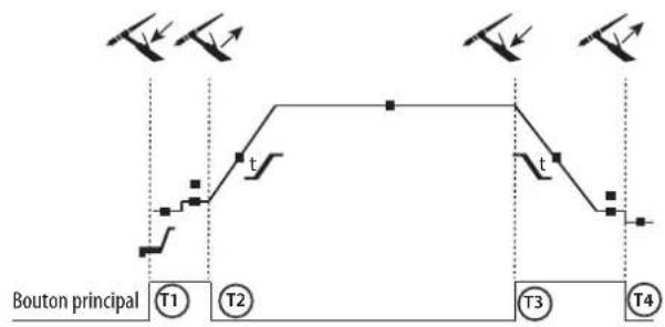
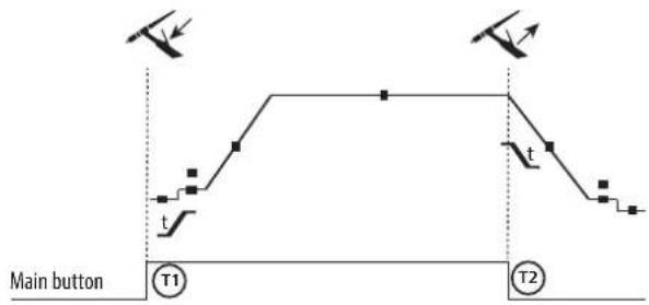
T1 - The main button is pressed, the cycle starts from the PreGas and stops in the I_Start phase.
T2 - The main button is released, the cycle continues in UpSlope and in welding.
T3 - The main button is pressed, the cycle switches to DownSlope and stops in I_Stop.
T4 - The main button is released, the cycle ends with PostGas.
For the dual-button torch, the secondary button is inactive.
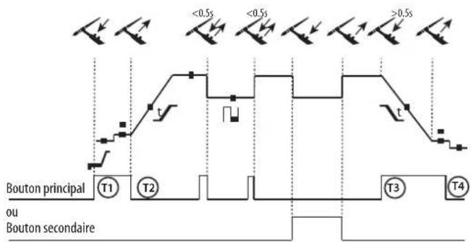
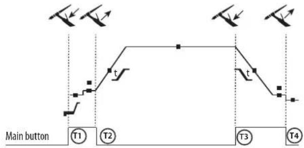
T1 - The main button is pressed, the cycle starts from the PreGas and stops in the I_Start phase.
T2 - The main button is released, the cycle continues in UpSlope and in welding.
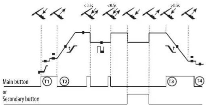
LOG: this operating mode is used in the welding phase:
- A short press of the main button (<0.5s) switches the current from I welding to I cold and vice versa.
- the secondary button is kept pressed, the current switches from I welding to I cold.
the secondary button is released, the current switches from I cold to I welding.
T3 – A long press on the main button (>0.5s), the cycle switches to DownSlope and stops in the I_Stop phase.
T4 - The main button is released, the cycle ends with PostGas.
For this mode it may be convenient to use the dual button torch option. The «up» trigger keeps the same function as the single button or trigger torch. The «down» button can, when pressed, switch to the cold current. The potentiometer of the torch, where available, can control of the welding current from 50% to 100% of the value displayed.
TRIGGER COMMAND CONNECTOR
text_image
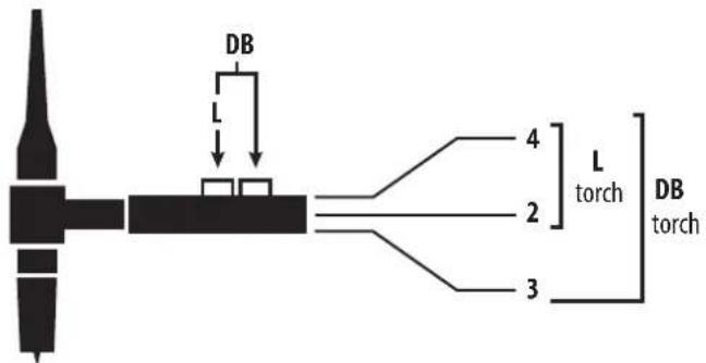
DB L 4 L torch 2 3 DB torch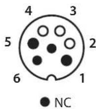
text_image
4 3 5 2 6 1 NC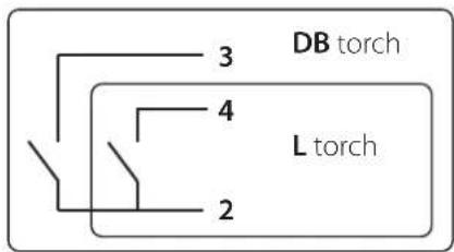
text_image
DB torch L torch 2 3 4Wiring diagram according to the type of torch. Electric diagram based on type of torch used.
| Torch type Wire description Pin | |||
| Torch double button Torch | with trigger | Common/Earth 2 | |
| Button 1 4 | |||
| Button 2 3 | |||
REMOTE CONTROL
The analog remote control operates in TIG and MMA processes.
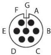
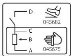
text_image
D 045682 C B A 045675Ref. 045699 External view Electric diagram according to the remote control type.
Connection
1- Plug the remote control into the connection at the back of the machine.
2- The HMI detects the presence of a remote control and offers a selection choice accessible by wheel.
Connections
The product is equipped with a female socket for a remote control.
The specific 7 pin male plug (option ref. 045699) allows the connection of different types of remote control. For the cabling layout, please see the diagram below.
| Wire description Pin | |||
| Foot pedal Manual remote control | 10 V A | ||
| Cursor B | |||
| Common/Earth C | |||
| Switch D | |||
Operating:
- Manual remote control (option ref. 045675):
The remote control enables the variation of current from 50% to 100% of the set intensity. In this configuration, all modes and functions of the machine are accessible and can be set.
• Foot pedal (option ref. 045682):
The foot pedal allows the current to be set from 10% to 100% of the set current. In TIG, the welding machine only operates in 2T mode. The upslope and downslope are not automatically managed by the current source, and are controlled by the user with the foot pedal.
RESOLUTION DES PROBLEMES
This device integrates a default management system.
A series of messages displayed on the control board allows for a fault and anomalies diagnosis.
| Error Meaning CAUSES SOLUTIONS | |||
 | Thermal protection | Maximum duty cycle reached.Ambient temprature above 40°C.Obstructed air input. | Wait for the indicator to turn off before resuming welding operations.Observe the operating factor and ensure good ventilation |
 | Torch fault Faulty torch(es) trigger(s) / button(s) | Make sure that nothing presses the torch trigger(s) when the product is switched on. | |
 | Pedal fault The pedal is pressed down | Make sure that nothing presses on the foot pedal when the product is turned on. | |
 | Push button(s) fault Push button(s) short-circuited | Check that none of the push buttons are pressed | |
| Troubleshooting Causes Solutions | |||
| TIG-MMA | The indicator is on but the product does not deliver any current. | The earth clamp or the electrode holder is not connected to the unit. | Check the connections |
| The product is connected to the mains, you are feeling tingling when touching the car body. | The earth contact is faulty. | Check the plug and the earth of your installation. | |
| The machine welds poorly. Polarity error | Check the recommended polarity (+/-) on the electrode box. | ||
| TIG | Unstable arc | Fault due to the tungsten electrode | Use an electrode size more suitable to the thickness of your metal. |
| Use an tungsten electrode properly prepared. | |||
| Use a tungsten electrode that is suitable for DC. | |||
| Gas flow incorrectly set | Check the gas flow rate on the cylinder pressure gauge. | ||
| The tungsten electrode becomes oxidized and tainted at the end of the welding | Gas problem, or gas flow stops too early | Check and tighten every gas connection. Wait for the electrode to cool down before switching off the glas flow. | |
| The electrode melts Polarity error | Check that the earth is connected to the (+) ant the torche to the (-) of the product | ||
WARRANTY CONDITIONS
The warranty covers defaults or manufacturing defects for 2 years from the date of purchase (parts and labour).
the warranty does not cover:
- Any other damage due to transport.
- Normal wear of parts (eg. : cables, clamps, etc.).
- Damages due to misuse (power supply error, dropping of the equipment, disassembling).
- Environment related failures (pollution, rust, dust).
In the event of a malfunction, return the unit to your dealer, enclosing:
- a dated proof of purchase (till receipt, invoice...)
- An explanatory note of the failure.
text_image
250 A V s Hz % I % I 10s 20s TIG - HF 2T TIG - Lift 4T 4TL06 + - SETUP Press 3text_image
250 A V s - Hz % I % I F (Hz) 10s 0s 20s TIG - HF TIG - Lift 2T 4T + Pulse JOB In Out SETUP Press 3text_image
850 A V ≤ Hz % JOB In Out SETUP Press 3 F(Hz) I TIG - HF TIG - Lift 2T Spottext_image
250 A V s Hz % JOB In Out SETUP Press 3 F (Hz) I TIG - HF 2T TIG - Lift Spot +/-text_image
DB L 4 L torch 2 DB torch 3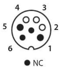
text_image
4 3 5 2 6 1 NC
text_image
DB torch L torch 2 3 4text_image
1 TIG HF 2 3text_image
1 TIG LIFT 2 3text_image
250 A V s Hz % JOB In Out SETUP Press 3 I % I 10s 20s TIG - HF 2T TIG - Lift 4T 4T LOG - + -text_image
250 A V s Hz % JOB In Out SETUP Print:3 I % I 10s 20s F (Hz) TIG - NF 2T TIG - Lift 4T - + Pulsetext_image
250 A V s Hz % JOB In Out SETUP Press 3 F (Hz) I TIG - HF 2T TIG - Lift Spottext_image
850 A V ≤ Hz % JOB In Out SETUP Press 3 F(Hz) I TIG - HF TIG - Lift 2T - + Pulse Spottext_image
DB L 4 L torch 2 3 DB torchtext_image
DB torch L torch 2 3 4text_image
850 A V s Hz % I % I 10s 20s TIG - HF 2T TIG - Lift 4T 4TL06 + - SETUP Press 3text_image
850 A V s - Hz % JOB In Out SETUP Press X I % I 10s 20s F(Hz) I - + TIG - HF 2T TIG - Lift 4T Pulsetext_image
850 A V s Hz % JOB In Out SETUP Press X F(Hz) I TIG - HF TIG - Lift 2T Spot +/-text_image
850 A V s - Hz % JOB in Out SETUP Press 3 F(Hz) TIG - HF 2T TIG - Lift + - Pulse Spot MOSI Powertext_image
DB L 4 L torch 2 DB torch 3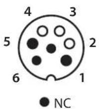
text_image
4 3 5 2 6 1 NC
text_image
DB torch L torch 2 3 4WAARSCHUWINGEN - VEILIGHEIDSINSTRUCTIES
ALGEMENE INSTRUCTIES
INTERFACE HUMAN MACHINE (IHM) (II)
1- Keuze procedure 5- Thermische beveiligingsindicator
2- Keuze trekker-module 6- Weergave en keuzes
3- Keuze opties procedures 7- Stand-by knop
4- Ingeven lasinstellingen
ELEKTRISCHE VOEDING - OPSTARTEN
text_image
220 A V s Hz % %I F (Hz) MMA MMA Pulse IN Out SETUP Prizes 3"text_image
1 TIG HF 2 3text_image
1 TIG LIFT 2 3text_image
250 A V s Hz % JOB In Out SETUP Press 3 10s 20s TIG - HF 2T TIG - Lift 4T 4T LOG - + -text_image
250 A V s Hz % JOB In Out SETUP Press 3 I % I 10s 20s F(Hz) TIG - HF 2T TIG - Lift 4T - + Pulsetext_image
850 A V s Hz % JOB In Out SETUP Press 3 TIG - HF TIG - Lift 2T - + Pulse Spottext_image
DB L 4 L torch 2 3 DB torch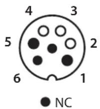
text_image
4 3 5 2 6 1 NC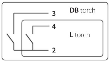
text_image
DB torch L torch 2 3 4text_image
1 2 3 TIG HFtext_image
1 TIG LIFT 2 3text_image
250 A V s Hz % JOB In Out SETUP Press 3 10s 20s I I - + TIG - HF 2T TIG - Lift 4T 4T LOGtext_image
850 A V s/Hz % JOB In Out SETUP Press 3 I %I 10s 20s F(Hz) TIG - HF 2T TIG - Lift 4T - + Pulsetext_image
850 A V s Hz % JOB In Out SETUP Press 3" F(Hz) I TIG - HF TIG - Lift 2T MHA Spot mWk Pulsetext_image
250 A V s Hz % JOB In Out SETUP Press 3 F(Hz) I TIG - HF TIG - Lift 2T T1 + - Pulse Spottext_image
Exploded view diagram of an electronic device with numbered components for identification*The duty cycles are measured according to standard EN60974-1 à 40°C and on a 10 min cycle.
While under intensive use (> to duty cycle) the thermal protection can turn on, in that case, the arc swictes off and the indicator switches on.
Keep the machine's power supply on to enable cooling until thermal protection cancellation.
The welding power source describes an external drooping characteristic.