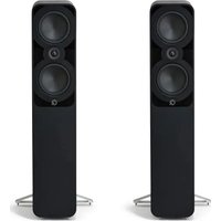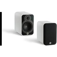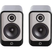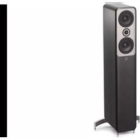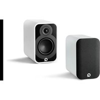
5010 - Speaker Q Acoustics - Free user manual and instructions
Find the device manual for free 5010 Q Acoustics in PDF.


User questions about 5010 Q Acoustics
0 question about this device. Answer the ones you know or ask your own.
Ask a new question about this device
Download the instructions for your Speaker in PDF format for free! Find your manual 5010 - Q Acoustics and take your electronic device back in hand. On this page are published all the documents necessary for the use of your device. 5010 by Q Acoustics.
USER MANUAL 5010 Q Acoustics
natural_image
Abstract black logo design with no text or symbolsACOUSTICS
5000 Series
OWNER'S MANUAL
ENGLISH EN
DEUTSCH DE
ESPAÑOL ES
FRANÇAIS FR
ITALIANO IT
NEDERLANDS NL
PORTUGUESE PT
SVENSKA SE
POLSKIE PL
РУССКИЙ RU
简 ZH
Contents
Important Safety Information and Warnings 4
Introduction 5
Package Contents....6
Preparation....7
Positioning....8
Connections 9
Running In 10
Aftercare 10
Warranty 10
Accessories....11
Specifications.... 12
Important Safety Information and Warnings
1. Safety Information and Warnings
Before making any connections to your loudspeakers make sure that all units in your sound system are switched off at the mains.
When switching on your sound system or changing input sources, set the main volume control at a low level. Turn up the level gradually.
NEVER play your sound system at full volume. The position of the volume control is deceptive and does not indicate the power level of the system. Using very high volume settings may damage your hearing.
1.1. Instructions
Read and understand these instructions before you use your loudspeakers. If damage is caused by failure to follow these instructions, the warranty will not apply. Please keep these instructions in a safe place.
2. Unpacking your loudspeakers

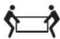
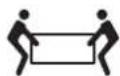
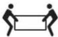
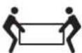
Unpack the loudspeakers fully. Lift the loudspeakers from the cartons by holding the cabinets. Do not use the protective bags to lift them. The 5040 loudspeakers are heavy - get assistance to lift them.
When manoeuvring loudspeakers, do not drag them across the floor as this may cause damage - lift each loudspeaker before moving it.
Check the loudspeaker carefully. If any items are damaged or missing, report this to your retailer as soon as possible.
Retain the packaging for future transport. If you dispose of the packaging, please do so following all recycling regulations in your area.
3. Installation
- Only use the accessories supplied with the product.
-
If you play your loudspeakers without their grilles fitted, be careful to protect the drive units from damage.
-
DO NOT dismantle the loudspeaker. You will invalidate the warranty.
• DO NOT connect your loudspeaker terminals to the mains supply. - Do NOT expose your loudspeakers to excessive cold, heat, humidity or sunlight.
- The use of this apparatus is indicated for tropical and/or moderate climates.
3.1. Moisture
- To reduce the risk of fire or electric shock, this apparatus should not be exposed to rain, moisture, dripping or splashing.
- Do not use this apparatus near water.
3.2. Servicing
Refer all servicing to qualified service personnel. Servicing is required when the apparatus has been damaged in any way, liquid has been spilled or objects have fallen into the apparatus, the apparatus has been exposed to rain or moisture, does not operate normally, or has been dropped.
4. Symbols used on this product

Hazard Warning Symbol
The ‘exclamation mark’ calls attention to features for which you should read this manual closely to prevent operation and maintenance problems.

Waste Electrical and Electronic Equipment Symbol
This symbol indicates that when the unit is to be discarded, it must be separated from other household-type waste and sent to separate collection facilities for recovery and recycling of electrical and electronic equipment.
Please make sure you are familiar with your local rules on the separate collection of electrical and electronic products.
Introduction
Thank you for purchasing Q Acoustics 5000 loudspeakers.
This manual is intended to take you through the setup and installation of the 5000 Series. It will help provide a trouble free setup and ensure optimum performance from the product. The 5000 Series is a range of loudspeakers designed to meet the highest expectations of dedicated 2-channel audiophiles and discerning movie enthusiasts.
The manual covers:
5010: Compact bookshelf loudspeaker with a 110mm (4.5 inches) bass driver.
5020: Bookshelf loudspeaker with a 125mm (5.0 inches) bass driver.
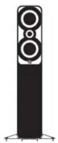
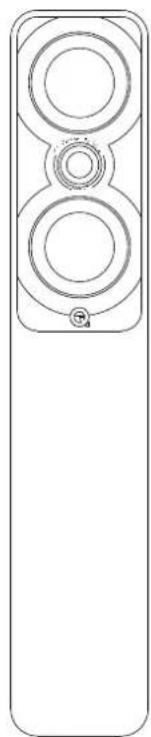
5040: Floorstander loudspeaker with two 125mm (5.0 inches) bass drivers.
5090: Centre loudspeaker with two 110mm (4.5 inches) bass drivers
Please read the instructions, important safety information and warnings carefully before installation and use, to ensure the safe and satisfactory operation of this product.
We hope you enjoy the Q Acoustics experience.
Package Contents
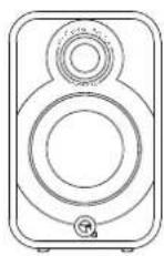
2×5010/5020

1 x Owners Manual

2 x Foam bung
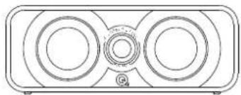
5090
natural_image
Line drawing of a two-tiered electronic device with circular and rectangular panels (no text or symbols)1 × 5090
1 x Owners Manual

2 x Foam bung
50405010 / 5020
natural_image
Line drawing of a vertical rectangular device with three circular tops and a small labeled tag (no text or symbols)1 × 5040

1 x Owners Manual

1 x Foam bung

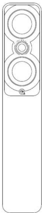
4 x Spike feet

4 x Spike cover

4 x M5 Screw
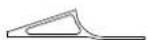
2 x Rear Stabiliser
Preparation

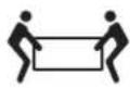
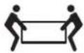
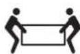
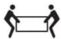
Lift the speakers from the cartons by holding the cabinets. Do not touch the driver units or use the protective bags to lift them. The 5040 loudspeakers are heavy - get assistance to lift them.
natural_image
Diagram of a mechanical device with mounting holes and a base plate (no text or symbols)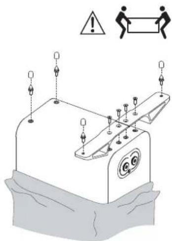
text_image
Safety warning diagram showing hazard symbols and safety instructions on a device with labeled components5040 Loudspeaker Installation
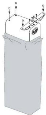
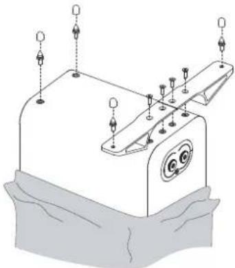
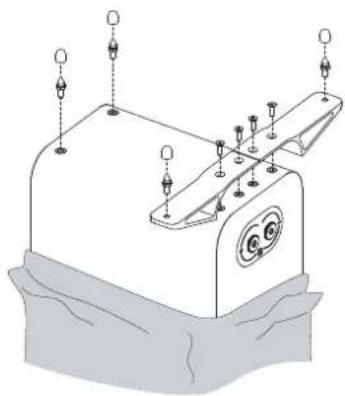
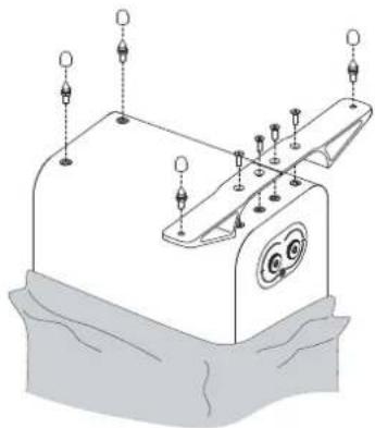
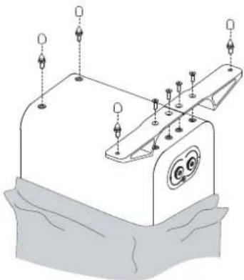
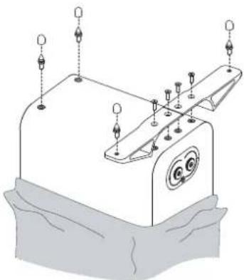
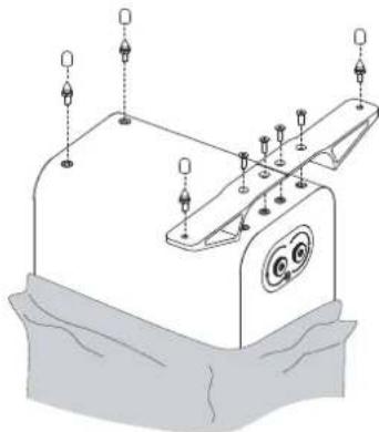
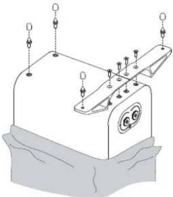
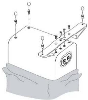
The 5040 loudspeakers are intended to be floor mounted only. We recommend you attach the support base during the unpacking process as in the diagram above, to avoid damage to the loudspeaker. However, you may attach it after the loudspeaker is unpacked, but you should protect the loudspeaker from damage by placing it on a soft cloth or similar. You must also take care to avoid damaging the drive units.

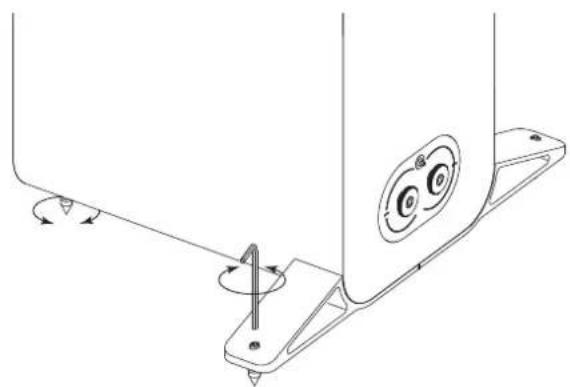
Spikes are sharp. Exercise care! Never place a spiked loudspeaker where it can cause damage! Always move your loudspeakers by lifting them - never drag them!
Thread the spikes fitted with locking nuts half way into the base and return the loudspeaker to the upright position (If you have a wood or stone floor push a spike cover over each spike before turning the speaker upright). When the speaker is the right way up, insert the Allen key into each rear spike from the top and adjust all the spikes in and out until the loudspeaker is level and stable.
natural_image
Technical line drawing of a mechanical component with mounting flanges and a central rotating knob (no text or symbols)Positioning
text_image
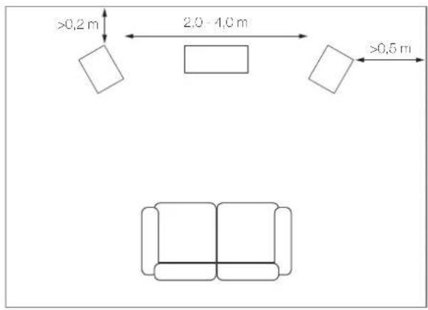
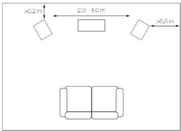
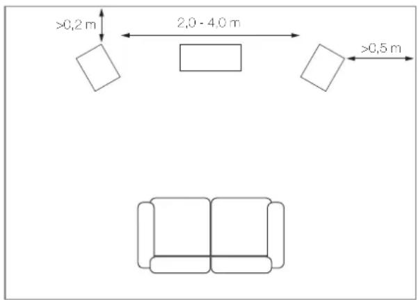
>0.2 m 2.0 - 4.0 m >0.5 m5010 / 5020
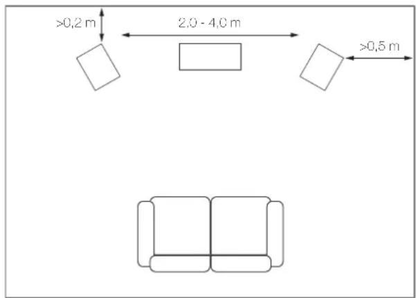
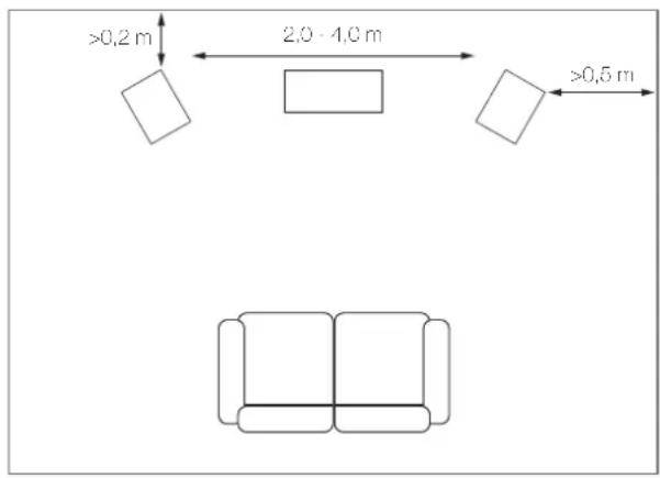
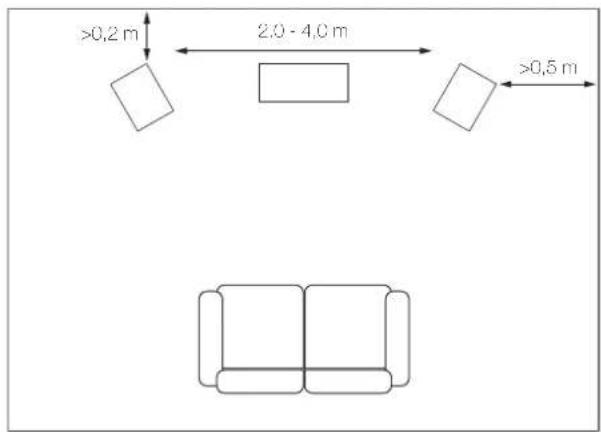
The 5010 / 5020 loudspeakers are ideally mounted on Q Acoustic floor stands and can also be wall mounted on Q Acoustic wall brackets. Stand mounted loudspeakers should be treated as floorstanding loudspeakers except that the loudspeaker may be placed a little closer to the back wall.
5040
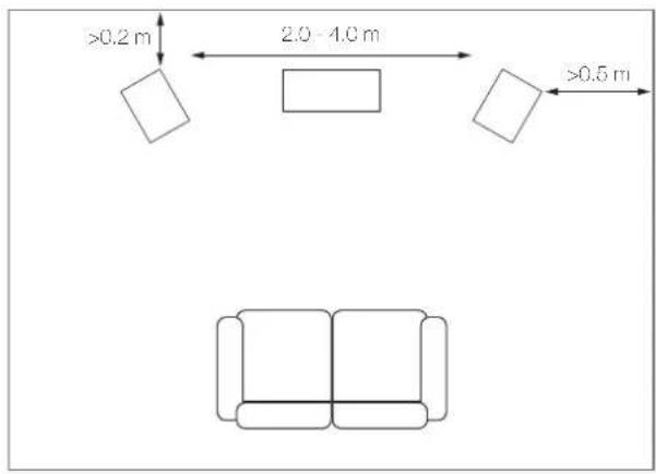
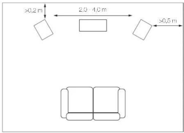
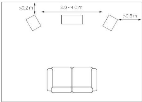
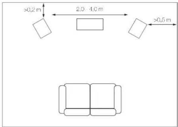
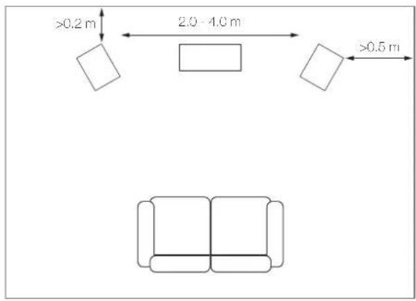
The 5040 loudspeakers should be positioned at least 0.2m from a back wall, 0.5m from the side walls and placed 2.0 – 4.0 m apart and equidistant from the seated listener. Turning the loudspeakers slightly inwards will sharpen the stereo image at the expense of a narrower sound stage.
5090
The 5090 loudspeaker should be positioned at least 0.2m from a back wall and central to a TV screen.
Foam Bung
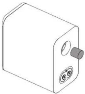
5000 series loudspeakers are rear ported and designed to work best with at least 0.2m of free space behind them. Generally, the closer the loudspeakers are to the rear wall the more the bass frequencies will be reinforced until they overwhelm the overall sound. In this instance closing the rear port with the foam bung will tend to reduce bass, which is useful when domestic circumstances demand that the loudspeaker is used closer to a rear wall, as when wall mounted.
natural_image
Line drawing of a rectangular electronic device with two circular ports and a handle (no text or symbols)Ensure that the bungs are fitted snugly into the port but avoid inserting them too far. You will find the overall level of bass is reduced but bass extension and definition will be increased. The optimal position of the loudspeakers will only be found through experimentation and by making small adjustments during the first few listening sessions.
Loudspeaker positioning in a room is not an exact science. Even experts will find it necessary to experiment. Try to achieve the best balance between bass quantity versus quality and vocal quality versus intelligibility.
Connections

Before making any connections to your loudspeakers make sure that all active units in your system are switched off at the mains. When switching on your sound system or changing input sources, set the main volume control at a low level. Turn up the level gradually.
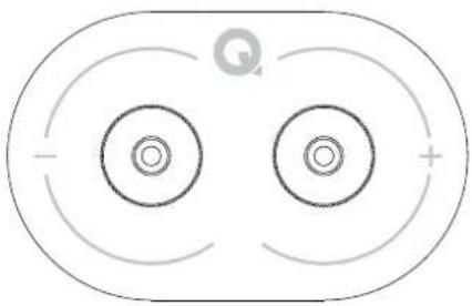
Terminals and Connectors
The 5010, 5020, 5040 and 5090 have standard two terminal crossovers.
natural_image
Pure diagram of concentric circles with directional arrows, no text or symbols presentLoudspeaker Cables
Specialist loudspeaker cables will offer a higher standard of reproduction than general purpose 'bell' or 'zip' wire. Use cable with generous amounts of copper for the front and centre channels. Thin cables reduce the bass and restrict the dynamic range. Surround (rear) channels are less critical.
Speaker cable has a stripe or tracer along one core. By convention this is connected to the positive terminals. The cables connecting the amplifier to the front loudspeakers should ideally be the same length. Never join cables - use complete lengths.
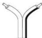
Preparing cables
Split the cable to a depth of about 40mm. Bare the wire to a depth of 10mm and twist the ends to gather any stray wires. Crop the cable leaving 7mm of bare wire exposed.
Connecting a terminal
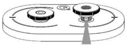
Unscrew the terminal anticlockwise to expose the mounting hole in the base of the terminal column. Insert the bare end of the cable into the hole. Relighten the terminal fully hand tight. Make sure there are no stray wires which could touch adjacent terminals. In the EU it is against safety regulations to use 4mm loudspeaker plugs.
natural_image
Pure mechanical diagram showing two circular components with a central triangular element (no text or symbols)Stereo Connections
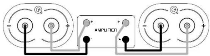
Connect the RED (+) terminal of the RIGHT loudspeaker to the RED, Positive (+) terminal on the RIGHT channel of the amplifier. Connect the BLACK (-) terminal of the loudspeaker to the matching BLACK, Negative (-) terminal of the amplifier. Repeat this procedure for the LEFT channel.
text_image
G + - AMPLIFIER + - GRunning In
In common with many types of complex mechanical systems the 5000 loudspeakers will not deliver their optimum performance until they have been in use for a certain initial running-in period. The correct performance of a loudspeaker depends in part on the compliance of the suspension materials used during manufacture and these will only attain their long term steady state once they are operating at the temperature and modulus of elasticity specified during the design phase. It can take several days for a loudspeaker which has been stored in a cold warehouse to finally reach room temperature and so we recommend at least 24 hours of normal use for the drive units to loosen up sufficiently for them to perform as the designer intended.
Aftercare
Cabinet Care

Clean cabinets only with a lightly dampened cloth. Do not use solvent based cleaning materials. Never use abrasives of any kind.
The cabinet surfaces will usually only require light dusting. Should an aerosol or other cleaner be used, apply the cleaner onto the cloth first and not directly onto the product. Test a small area first, as some cleaning products may damage the finish. Avoid products that are abrasive, or contain acid or alkaline agents. Do not use any cleaning materials on the drive units and avoid touching them as damage may result.
Grilles
Grilles should only be cleaned using a soft brush when necessary.
If using the loudspeakers with the grilles removed, remember to replace them if pets or children are present.
Drive Units
Do not touch the drive units as they are easily damaged when exposed.
Warranty
Q Acoustics passive loudspeaker products are warranted free of defects in materials and workmanship for a period of 4 years from the date of purchase. During the warranty period Q Acoustics will, at its option, repair or replace any product found to be faulty after inspection by the company or its appointed distributor or agent.
Misuse and fair wear and tear are not covered by warranty.
Goods for repair should in the first instance be returned to the supplying retailer. If this is not possible contact Q Acoustics or their appointed distributor for your area to determine the correct warranty procedure. If possible the original packaging should be used to return the product as damage sustained during transit to the repair centre is not covered by the warranty. The warranty does not in any way affect your legal rights.
Warranty can be extended to 5 years by registering your product at qacoustics.co.uk/register.
For service information contact: support@qacoustics.co.uk
Q Acoustics
Woodside 2, Dunmow Road
Bishops Stortford, Hertfordshire, UK
CM23 5RG
For any additional information not contained within this manual, support questions and/or requests, please visit our on-line Knowledge Base Portal at: www.qacoustics.co.uk/FAQs
Accessories
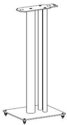
Q 3000FSi Speaker Stands (Pair)
Black and White
Suitable for 5010 / 5020
natural_image
Line drawing of a three vertical cylindrical stand with mounting feet (no text or symbols)Dimensions (H x W X D):
250×682×290mm
26.9 × 9.8 × 11.4 in
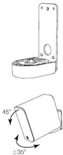
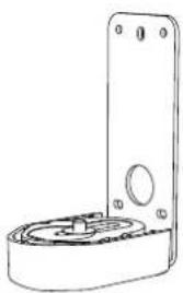
Q 3000WB Wall Bracket (Single)
Black and White
Suitable for 5010
natural_image
Technical line drawing of a mechanical bracket with two views: top shows top view of circular component, bottom shows 45° and ±35° rotation arrows (no text or symbols)Dimensions (H x W X D):
165 × 70 × 99 mm
6.5×2.8×3.9 in
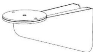
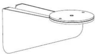
Q WB75 Wall Bracket (Single)
Black and white
Suitable for 5020 / 5090
natural_image
Simple line drawing of a mechanical component with a circular top and handle (no text or symbols)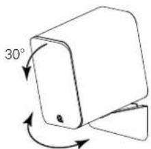
text_image
30°5020: ±35°
5090: ±10°
Dimensions (H x W X D):
119×102×231 mm
4.7 × 4.0 × 9.1 in
Specifications


Product 5010 5020
Bass unit: 1 x 110 mm (4.5 in) 1 x 125 mm (5.0 in)
Treble unit: 1 x 25 mm (1.0 in) 1 x 25 mm (1.0 in)
Frequency Response (-6dB): 56 Hz - 30 kHz 53 Hz - 30 kHz
Nominal Impedance: 6 Ω 6 Ω
Minimum Impedance: 3.3 Ω 3.3 Ω
Sensitivity (2.83V @ 1kHz): 86.3 dB/W/m 87.8 dB/W/m
Recommended amplifier power: 15 – 90 W 25 – 100 W
Crossover Frequency: 2.5 kHz
Effective volume: 5.0 L 6.8 L
Dimensions (per speaker) HxWxD: 264 x 160 x 263 mm
(10.4 × 6.3 × 10.4 in)
Weight (per speaker): 5.6 kg (12.3 lbs)
2.5 kHz
284 × 180 × 293 mm
(11.2 × 7.1 × 11.5 in)
7.0 kg (15.4 lbs)

Product 5040 5090
Bass unit: 2 x 125 mm (5.0 in) 2 x 110 mm (4.5 in)
Treble unit: 1 x 25 mm (1.0 in) 1 x 25 mm (1.0 in)
Frequency Response (-6dB): 39 Hz – 30 kHz 57 Hz – 30 kHz
Nominal Impedance: 6 Ω 6 Ω
Minimum Impedance: 3.0 Ω 3.2 Ω
Sensitivity (2.83V @ 1kHz): 91.5 dB/W/m 90.5 dB/W/m
Recommended amplifier power: 25 – 150 W 25 – 150 W
Crossover Frequency: 2.5 kHz 2.1 kHz
Effective volume: 27.0 L 7.8 L
Dimensions (per speaker) HxWxD: 967 x 361 x 293 mm 164 x 430 x 243 mm
(38.1 x 14.2 x 11.5 in) (6.5 x 16.9 x 9.6 in)
inc. spikes & stabiliser
Weight (per speaker): 18.0 kg (39.7 lbs) 8.5 kg (18.7 lbs)
Inhaltsverzeichnis
natural_image
Line drawing of a two-port device with circular ports and a central hub (no text or symbols)1 × 5090
natural_image
Front view of a vertical rectangular device with three circular cutouts and a small lock icon at the bottom (no text or symbols)1 × 5040
natural_image
Diagram of a battery pack with mounting holes and a control panel (no text or symbols)!
natural_image
Technical line drawing of a mechanical device with mounting holes and a circular component (no text or symbols)natural_image
Technical line drawing of a mechanical component with mounting flanges and a central rotating knob (no text or symbols)Aufstellung
text_image
>0,2 m 2.0 - 4.0 m >0,5 m5010 / 5020
natural_image
Line drawing of a rectangular electronic device with two ports and a handle (no text or symbols)natural_image
Pure diagram of concentric circles with directional arrows, no text or symbols presentLautsprecherkabel
natural_image
Pure mechanical component diagram without any text, numbers, or symbolsStereoanschlüsse
Woodside 2, Dunmow Road
Bishops Stortford, Hertfordshire, UK
CM23 5RG
natural_image
Line drawing of a vertical cylindrical platform with three vertical supports, mounted on a base with wheels (no text or symbols)natural_image
Technical line drawing of a mechanical bracket with two views showing angular measurements (45° and ±35°) — no text or symbols present.text_image
5020: +35" 5090: ±10°natural_image
Line drawing of a two-tiered electronic device with circular components and a central hub (no text or symbols)1 × 5090
natural_image
Front view of a vertical rectangular device with three circular cutouts and a small labeled icon (no text or symbols on the device itself)1 × 5040
natural_image
Diagram of a mechanical device with mounting holes and a base plate (no text or symbols)!
natural_image
Technical line drawing of a mechanical component with mounting holes and a circular feature (no text or symbols)natural_image
Technical line drawing of a mechanical assembly with mounting bracket and circular components (no text or symbols)Colocación
text_image
>0,2 m 2,0 - 4,0 m >0,5 m5010 / 5020
natural_image
Line drawing of a rectangular electronic device with two ports and a central knob (no text or symbols)natural_image
Pure diagram of concentric circles with directional arrows, no text or symbols presentCables de altavoz
natural_image
Pure mechanical diagram showing two circular components with a central shaft and base, no text or symbols present.Conexiones estéreo
Woodside 2, Dunmow Road
Bishops Stortford, Hertfordshire, Reino Unido
CM23 5RG
natural_image
Simple line drawing of a three vertical cylindrical stand with mounting feet (no text or symbols)Dimensiones (Al x An x P): 250 x 682 x 290 mm 26,9 x 9,8 x 11,4 pulg.
natural_image
Technical line drawing of a mechanical bracket with two 45° and 35° angular annotations (no text or symbols on the diagram itself)Dimensiones (Al x An x P): 165 x 70 x 99 mm 6,5 x 2,8 x 3,9 pulg.
text_image
5020: +35" 5090: ±10°Dimensiones (Al x An x P): 119 x 102 x 231 mm 4,7 x 4,0 x 9,1 pulg.
Especificaciones


Producto 5010 5020
Unidad de graves: 2 x 110 mm (4,5 pulg.) 1 x 125 mm (5,0 pulg.)
natural_image
Pure technical line drawing of a two-port device with circular ports and a central hub (no text or symbols)1 × 5090
natural_image
Line drawing of a rectangular electronic device with three circular ports and a small indicator button (no text or symbols)1 × 5040
natural_image
Diagram of a battery with mounting holes and a cover, no text or symbols present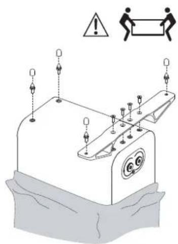
text_image
Diagram of a mechanical device with warning symbols and labeled components, including warning signs and a warning box.natural_image
Technical line drawing of a mechanical assembly with mounting bracket and circular component (no text or symbols)Positionnement
text_image
>0,2 m 2.0 - 4.0 m >0,5 m5010 et 5020
natural_image
Isometric line drawing of a rectangular electronic device with two ports and a central knob (no text or symbols)natural_image
Pure electrical circuit lines without any symbolsCâbles d'enceinte
natural_image
Pure mechanical diagram showing two gears and a central shaft (no text or symbols)Connexions stéréo
Woodside 2, Dunmow Road
Bishops Stortford, Hertfordshire, Royaume-Uni
CM23 5RG
natural_image
Line drawing of a three-legged platform with wheels and a support frame (no text or symbols)Dimensions (L×H×P):
250 x 682 x 290 mm
26,9×9.8×11.4 in
Q 3000WB Support mural (simple)
Noir et blanc
natural_image
Technical line drawings of a mechanical bracket with two views showing angular measurements (45° and ±35°) — no text or symbols present.Dimensions (L×H×P):
165×70×99mm
6,5×2,8×3,9 in
Q WB75 Support mural (simple)
Noir et blanc
natural_image
Line drawing of a mechanical component with a circular top and flange (no text or symbols)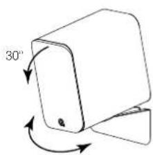
text_image
30°5020:±35°
5090: +10°
Dimensions (L×H×P):
119 x 102 x 231 mm
4,7×4,0×9,1 in
Aigu : 1 x 25 mm (1,0 pouce) 1 x 25 mm (1,0 pouce)
Aigu : 1 x 25 mm (1,0 pouce) 1 x 25 mm (1,0 pouce)
natural_image
Diagram of a mechanical device with mounting holes and a base plate (no text or symbols)!
natural_image
Technical line drawing of a mechanical component with mounting holes and a circular feature (no text or symbols)natural_image
Technical line drawing of a mechanical component with mounting flanges and a central rotating knob (no text or symbols)Posizionamento
text_image
>0,2 m 2,0 - 4,0 m >0,5 m5010 / 5020
natural_image
Isometric line drawing of a rectangular electronic device with two ports and a handle (no text or symbols)natural_image
Pure diagram of two concentric circles with directional arrows, no text or symbols presentnatural_image
Pure mechanical component diagram without any text, numbers, or symbolsCollegamenti stereo
Woodside 2, Dunmow Road
Bishops Stortford, Hertfordshire, Regno Unito
CM23 5RG
natural_image
Simple line drawing of a three vertical cylindrical stand with mounting feet (no text or symbols)Dimensioni (L×A×P):
250×682×290mm
26,9×9.8×11.4in
Q 3000WB Staffa da parete (singola)
Bianco e nero
Idoneo per 5010

natural_image
Technical line drawing of a mechanical bracket with mounting holes and a central circular feature (no text or symbols)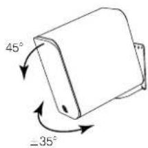
text_image
45° -35°Dimensioni (L×A×P):
165×70×99mm
6,5×2,8×3.9 in
natural_image
Line drawing of a mechanical component with a circular top and side handle (no text or symbols)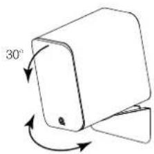
text_image
30°5020: ±35°
5090: ±10
Dimensioni (L×A×P):
119×102×231mm
4,7×4,0×9.1 in
Specifiche


Prodotto 5010 5020
18,0 kg (39,7 libbre)
2,1 kHz
7,8 L
164 x 430 x 243 mm
(6,5 × 16,9 × 9,6 pollici)
8,5 kg (18,7 libbre)
Inhoudsopgave
natural_image
Diagram of a battery pack with mounting holes and a circuit board (no text or symbols)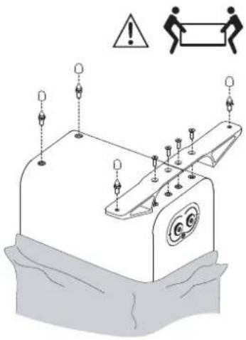
text_image
Diagram illustrating a mechanical or electrical component with warning symbols and labeled components, including a warning sign and human figure.natural_image
Technical line drawing of a mechanical component with mounting flanges and a central rotating knob (no text or symbols)Positionering
text_image
>0,2 m 2,0 - 4,0 m >0,5 m5010 / 5020
natural_image
Line drawing of a rectangular electronic device with two ports and a handle (no text or symbols)natural_image
Pure electrical circuit lines without any symbolsLuidsprekerkabels
natural_image
Pure mechanical diagram showing two circular components with a central triangular component and a base, no text or symbols present.Stereoansluitingen
Woodside 2, Dunmow Road
Stortford, Hertfordshire, GB
CM23 5RG
natural_image
Simple line drawing of a three vertical cylindrical structure mounted on a base, with mounting feet at both ends (no text or symbols)Afmetingen (B×H×D):
250×682×290mm
26.9×9.8×11.4 in
Q 3000WB Wandbeugel (1 stuk)
Zwart en wit
Geschikt voor 5010

natural_image
Technical line drawing of a mechanical bracket with mounting holes and a central circular feature (no text or symbols)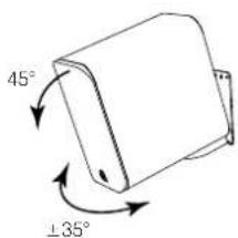
text_image
45° ±35°Afmetingen (B×H×D):
165 × 70 × 99 mm
6.5×2.8×3.9 in
Q WB75 Wandbeugel (1 stuk)
Zwart en wit
natural_image
Simple line drawing of a mechanical component with a circular top and side protrusions (no text or symbols)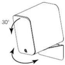
text_image
30°5020: ±35°
5090: ±10°
Afmetingen (B×H×D):
119 x 102 x 231 mm
4.7×4.0×9.1in
Specifications


Product 5010 5020
Basunit: 1 x 110 mm 1 x 125 mm
Treble-unit: 1 x 25 mm 1 x 25 mm
Frequentierespons (-6dB): 56 Hz - 30 kHz 53 Hz - 30 kHz
(38.1 × 14.2 × 11.5 in)
natural_image
Line drawing of a two-port device with circular ports and a central hub (no text or symbols)1 × 5090
1 x manual do utilizador
natural_image
Front view of a vertical rectangular device with three circular cutouts and a small lock icon at the bottom (no text or symbols)1 × 5040

1 x manual do utilizador

1 x tampa de espuma

4 x pés de espigão
natural_image
Diagram of a mechanical device with mounting holes and a base plate (no text or symbols)
natural_image
Technical line drawing of a mechanical device with mounting holes and a circular button (no text or symbols)natural_image
Technical line drawing of a mechanical assembly with mounting base and circular component (no text or symbols)Posicionamento
text_image
>0,2 m 2,0 - 4,0 m >0,5 m5010 / 5020
natural_image
Line drawing of a rectangular electronic device with two circular ports and a handle (no text or symbols)natural_image
Pure diagram of concentric circles with directional arrows, no text or symbols presentCabos de altifalantes
natural_image
Pure mechanical diagram showing two gears and a shaft (no text or symbols)Ligações estéreo
Ligue o terminal VERMELHO (+) do altifalante DIREITO ao terminal Positivo VERMELHO (+) no canal DIREITO do amplificador. Ligue o terminal PRETO (-) do altifalante ao terminal Negativo PRETO (-) do amplificador. Repita o procedimento para o canal ESQUERDO.

text_image
AMPLIFIERRodagem
Woodside 2, Dunmow Road
Bishops Stortford, Hertfordshire, Reino Unido
CM23 5RG
natural_image
Simple line drawing of a three vertical cylindrical stand with wheels at both ends (no text or symbols)natural_image
Simple line drawing of a mechanical component with a circular top and side features (no text or symbols)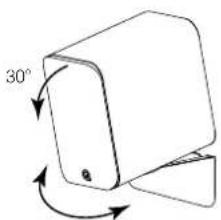
text_image
30°5020: ±35°
5090: ±10°
natural_image
Line drawing of a two-part electronic device with circular components and a central knob (no text or symbols)1 × 5090
1 x bruksanvisning

2 x skumgummipropp
50405010 / 5020
natural_image
Front view of a vertical rectangular device with three circular cutouts and a small lock icon at the bottom (no text or symbols)1 × 5040

1 x bruksanvisning

1 x skumgummipropp

4 x spikfötter
natural_image
Diagram of a battery pack with labeled terminals (O, D) and a circular button, no readable text or symbols present.
natural_image
Technical line drawing of a mechanical device with mounting holes and a circular component (no text or symbols)natural_image
Technical line drawing of a mechanical component with rotating arrows indicating motion (no text or symbols)Positionering
text_image
>0,2 m 2,0 - 4,0 m >0,5 m5010/5020
natural_image
Line drawing of a rectangular electronic device with two ports and a handle (no text or symbols)natural_image
Pure electrical circuit lines without any symbolsHögtalarkablar
natural_image
Pure mechanical diagram showing two gears and a central shaft (no text or symbols)Stereoanslutningar
Woodside 2, Dunmow Road
Bishops Stortford, Hertfordshire, Storbritannien
CM23 5RG
natural_image
Line drawing of a three-side vertical pole with mounting feet (no text or symbols)Mått (B x H x D mm):
250×682×290mm
26,9×9,8×11.4 tum
natural_image
Technical line drawing of a mechanical bracket with mounting holes and a central circular feature (no text or symbols)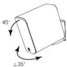
text_image
45° ±35°Mått (B x H x D mm):
165×70×99mm
6.5×2.8×3.9 tum
natural_image
Simple line drawing of a mechanical component with a circular top and side plate (no text or symbols)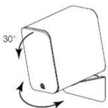
natural_image
Simple 3D diagram of a mechanical component with angular annotation (30°) and directional arrows, no readable text or symbols.5020: ±35°
5090: ±10°
Mått (B x H x D mm):
119×102×231mm
4,7×4,0×9,1 tum
Specifikationer
Produkt 5010 5020
Basenhet: 1 x 110 mm (4,5 tum) 1 x 125 mm (5.0 tum)
Diskantenhet: 1 x 25 mm (1,0 tum) 1 x 25 mm (1,0 tum)
natural_image
Pure technical line drawing of a two-part mechanical device with no text or symbols1 × 5090
natural_image
Line drawing of a vertical rectangular device with three circular tops and a small lock at the bottom (no text or symbols)1 × 5040
natural_image
Diagram of a mechanical device with mounting holes and a base, no text or symbols present!
natural_image
Technical line drawing of a mechanical component with mounting holes and a circular feature (no text or symbols)natural_image
Technical line drawing of a mechanical component with mounting base and circular features (no text or symbols)Ustawianie
text_image
>0,2 m 2,0 - 4,0 m >0,5 m5010/5020
natural_image
Line drawing of a rectangular electronic device with two ports and a handle (no text or symbols)natural_image
Pure electrical circuit lines without any symbolsKable głośnikowe
natural_image
Pure mechanical component diagram without any text, numbers, or symbolsPodłączenia stereo
Woodside 2, Dunmow Road
Bishops Stortford, Hertfordshire, Wielka Brytania
CM23 5RG
natural_image
Line drawing of a vertical cylindrical platform with three vertical supports, mounted on a base (no text or symbols)natural_image
Technical line drawing of a mechanical bracket with mounting holes and a central circular feature (no text or symbols)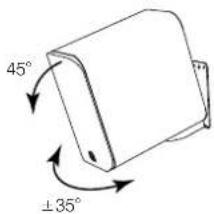
text_image
45° ±35°natural_image
Line drawing of a mechanical component with a circular top and side protrusions (no text or symbols)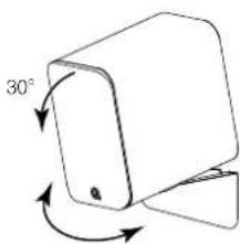
text_image
30°5020: ±35°
5090: ±10°
natural_image
Line drawing of a two-port electronic device with circular ports and a central hub (no text or symbols)natural_image
Front view of a rectangular electronic device with three circular ports and a small lock icon (no text or symbols)natural_image
Diagram of a battery pack with mounting holes and a lid, no text or symbols present!
natural_image
Technical line drawing of a mechanical device with mounting holes and a circular component (no text or symbols)natural_image
Technical line drawing of a mechanical assembly with mounting base and circular component (no text or symbols)Размещение
text_image
>0,2 m 2.0 - 4.0 m >0,5 m5010/5020
natural_image
Line drawing of a rectangular electronic device with two ports and a handle (no text or symbols)natural_image
Pure diagram of concentric circles with directional arrows, no text or symbols presentАкустические кабели
natural_image
Pure mechanical diagram showing two gears and a central shaft without any text or symbolsWoodside 2, Dunmow Road
Bishops Stortford, Hertfordshires, UK CM23 SRG
natural_image
Line drawing of a three vertical cylindrical stand with wheels at the base (no text or symbols)natural_image
Technical line drawing of a mechanical bracket with mounting holes and a central circular feature (no text or symbols)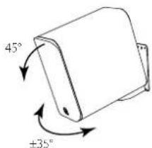
text_image
45° ±35°natural_image
Simple line drawing of a mechanical component with a circular top and flange (no text or symbols)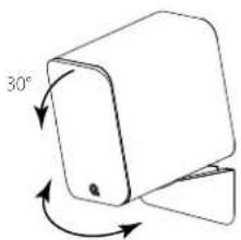
natural_image
Simple line drawing of a 30-degree angled object with directional arrows indicating rotation (no text or symbols)5020: ±35°
5090: ±10°
natural_image
Line drawing of a two-cylinder electronic device with no text or symbols1 台 5090

2 个泡沫塑料塞1 本用户手册
50405010 / 5020
natural_image
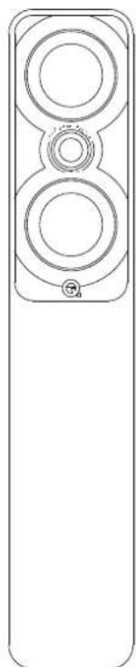
Front view of a vertical rectangular device with three circular cutouts and a small labeled button (no text or symbols visible)1台5040
1 本用户手册

1 x 泡沫塑料塞

4 x 脚钉

1 x 螺丝保护器

4 x M5 螺钉
2 x 后稳定器
准备

natural_image
Diagram of a battery pack with mounting points and a control panel (no text or symbols)!
natural_image
Technical line drawing of a mechanical device with mounting holes and a circular component (no text or symbols)5040 音箱安装
natural_image
Technical line drawing of a mechanical component with mounting base and circular features (no text or symbols)定位
text_image
>0.2 m 2.0 - 4.0 m >0.5 mnatural_image
Isometric line drawing of a rectangular electronic device with two ports and a handle (no text or symbols)natural_image
Pure diagram of concentric circles with directional arrows, no text or symbols present音箱线缆
natural_image
Pure mechanical diagram showing two gears and a valve without any text or symbols标准连接
Woodside 2, Dunmow Road
Bishops Stortford, Hertfordshire, UK
CM23 5RG
natural_image
Line drawing of a three vertical cylindrical stand with mounting feet (no text or symbols)250 x 682 x 290mm
26.9×9.8×11.4英寸
Q 3000WB 墙壁支架
黑色或白色两面
适用于 5010
natural_image
Technical line drawing of a mechanical bracket with mounting holes and a circular component (no text or symbols)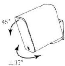
text_image
45° ±35°165 x 70 x 99mm
6.5×2.8×3.9英寸
Q WB75 墙壁支架
黑色或白色两面
适用于 5020 / 5090
natural_image
Line drawing of a mechanical component with a circular top and side arm (no text or symbols)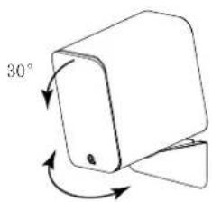
text_image
30°5020: ±35°
5090: ±10°
119 x 102 x 231mm
4.7 x 4.0 x 9.1 英寸
规格


产品 50105020
交叉频率 2.5 kHz 2.5 kHz
有效体积 5.01.6.81.
尺寸(每一扬声器)高x宽x深 264 x 160 x 263 mm
Our policy is one of continuous product improvement.
We reserve the right to change the designs and specifications without notice.
This document contains information that is subject to change without notice
Q18103-IS-ALL_r1