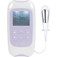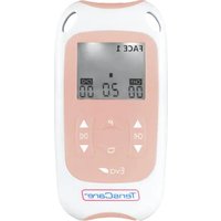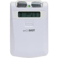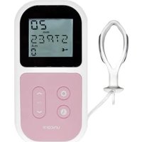
Unifit - Pain therapy device TensCare - Free user manual and instructions
Find the device manual for free Unifit TensCare in PDF.


User questions about Unifit TensCare
0 question about this device. Answer the ones you know or ask your own.
Ask a new question about this device
Download the instructions for your Pain therapy device in PDF format for free! Find your manual Unifit - TensCare and take your electronic device back in hand. On this page are published all the documents necessary for the use of your device. Unifit by TensCare.
USER MANUAL Unifit TensCare
natural_image
Diagram of a mobile phone connected to a circular device with an ear connector (no text or symbols present)Connect the unit to the electrode pads Conecte la unidad a los parches de electrodos
text_image
Power ButtonPress and hold the power button Mantenga apretado el botón de encendido Appuyez sur le bouton d'alimentation et maintenez-le enfoncé Drücken und halten Sie die Einschalttaste Tieni premuto il pulsante di accensione
5
text_image
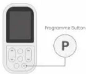
Programme Button Ptext_image
Diagram showing a mobile device connected to a human body with an electrical circuit diagram, indicating a comparison or comparison scenario.text_image
Mode Button MSelect a mode by pressing the button MODE Seleccione un modo pulsando el botón M Sélectionnez un mode en appuyant sur le bouton M Wählen Sie einen Modus durch Drücken die M-Taste Scegli una modalità premendo il pulsante M
6
text_image
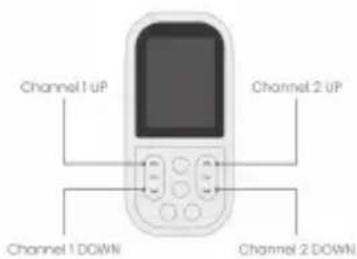
Channel 1 UP Channel 2 UP Channel 1 DOWN Channel 2 DOWNRegulate the intensity for each channel Regule la intensidad para cada canal Régler l'intensité pour chaque canal Regulieren Sie die Intensität für jeden Kanal Regolare l'intensità per ciascun canale
Dear Customer,
Thank you for choosing Unifit. TensCare stands for high-quality, thoroughly tested products for the applications in the areas of gentle electrotherapy, muscle toning, continence management and pain relief during labour.
Please read these instructions for use carefully and keep them for later use, be sure to make them accessible to other users and observe the information they contain.
Best regards,
Your TensCare Team
Contents
- Introduction 6
- Intended Use 6
- Contents 6
- Safety Guidelines 7
- Unifit Device 10
- Directions for Use 11
- TENS Programmes 14
- EMS Programmes 16
- Massage Programmes 18
-
Pad Placement 19
-
Charging Unifit 23
-
Cleaning & Storage 25
-
Replacement Parts 25
-
Warranty 25
-
Troubleshooting 27
-
EMC 28
-
Disposal of Electronic Products (WEEE) 28
-
Technical Specification 29
01. Introduction
Unifit combines the treatment capabilities of a TENS device, an EMS or NMES device, and a relaxing massage stimulator in one unit.
It sends a small and gentle stimulation (similar to your natural nerve impulses) to the muscles being treated via two or four auto-adhesive electrode pads, in order to help you to firm and tone your body.
Rehabilitation: neuromuscular facilitation, muscle re-education, muscle training, prevention/slowing of atrophy/hypotrophy. EMS has been shown to improve blood flow and circulation.
Sports training: improve muscle strength and performance; warm up, strength, speed, power, resistance, endurance and recovery.
Muscle relaxation: loosening up of muscular tension, improving muscular fatigue symptoms and reduced fatigue and muscle tension.
02. Intended Use
Unifit is a medical device designed to be used in the home healthcare environment to improve muscle tone and bulk, as well as provide symptomatic relief and management of acute or chronic localised pain and muscle pain. It is suitable for use by all who can control the device and understand the instructions.
Do not use the device for any purpose other than this intended use.
Warning: Not suitable for use in children without medical supervision.
03. Contents
The pack contains:
1 x Unifit unit
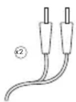
2 x Lead wires (L-CPT)
4 x 50x50mm electrodes (E-CM5050)
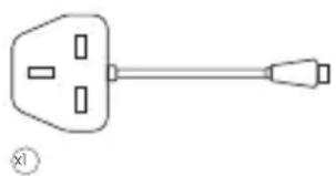
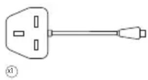
1 x Charging adaptor (EU/UK) (X-UNICH)
1 x Detachable belt clip
1 x Storage pouch
1 x Instructions for use
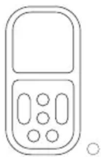
natural_image
Simple line drawing of a mobile phone with keypad and buttons (no text or symbols)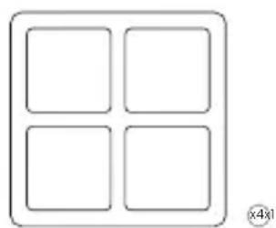
natural_image
Simple diagram of four empty squares arranged in a 2x2 grid within a rounded rectangle (no text or symbols)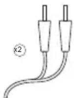
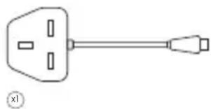
natural_image
Simple line drawing of a plug with four slots and a connector (no text or symbols)
04. Safety Guidelines

Contraindications
- Do not use if you have a pacemaker (or if you have a heart rhythm problem) or with any electronic medical devices. Using this unit with electronic medical devices may cause erroneous operation of the device. Stimulation in the direct vicinity of an implanted device may affect some models.
- Do not use during the first three months of pregnancy. It is not known whether TENS and EMS may affect foetal development.
- Do not use on the abdomen in the later stages of pregnancy. Stop using immediately if you experience unexpected contractions.

Warnings
- Do not use when driving, operating machinery, or similar actions needing muscular control. Loose electrode pads, damaged leads, or sudden changes in contact may cause brief involuntary muscle movements.
- Do not use to mask or relieve undiagnosed pain. This may delay diagnosis of a progressive condition.
- Do not use if you have, in the area being treated: active or suspected cancer or undiagnosed pain with a history of cancer. Stimulation directly
through a confirmed or suspected malignancy should be avoided as it may stimulate growth and promote spread of cancer cells.
- Do not use simultaneously with high frequency hospital diagnostic/therapeutic equipment. Doing so may result in burns at the site of the electrodes and possible damage to device.
- Do not use electrodes on the front of the neck. Stimulation on the front of the neck can affect your heart rate or cause contraction of the throat.
- Do not use electrodes across the chest. Very strong stimulation across the chest may cause an extra heartbeat and/or rhythm disturbances to your heart, which could be lethal.
- Do not use in close proximity (e.g. 1 m) to a shortwave or microwave as this may produce instability in the stimulator output.
- Do not apply near the thorax because the introduction of electrical current may increase the risk of cardiac fibrillation.
- Stimulation should not be applied across or through the head, directly on the eyes, covering the mouth, on the front of the neck (especially the carotid sinus), or from electrodes placed on the upper back or crossing over the heart.

Cautions
- Caution should be used if you have a bleeding disorder as stimulation may increase blood flow to the stimulated region.
- Caution should be used if you have suspected or diagnosed epilepsy as electrical stimulation may affect seizure threshold.
- Caution should be observed when using the device at the same time as being connected to monitoring equipment with body worn electrode pads. It may interfere with the signals being monitored.
- Caution should be used following recent surgical procedures. Stimulation may disrupt the healing process.
- Do not permit use by children unable to understand the instructions or persons with cognitive disabilities, i.e.; Alzheimer's disease or dementia.
- Keep away from children under 5 years of age, pets and pests. Long lead wires and charging cables - risk of strangulation in infants.
- Caution should be observed when using Unifit at high strength settings. Prolonged use at high settings may cause muscle injury or tissue inflammation. Unifit is capable of delivering outputs in excess of 10 mA (RMS) or 10 V averaged over any period of 1 sec.
- Not intended for use in an oxygen rich environment.
- Not intended for use in conjunction with flammable anaesthetics or flammable agents.
• The patient is an intended operator.
- Do not service and maintain the device while in use with a patient.
- Maintenance and all repairs should only be carried out by an authorized agency. The manufacturer will not be held responsible for the results of maintenance or repairs by unauthorized persons.
- If necessary, we will provide circuit diagrams, component part lists or other information that will assist authorized service personnel to repair the device.
- Do not immerse your device in water or place it close to excessive heat such as a fireplace or radiant heater or sources of high humidity such as a nebulizer or kettle as this may cause it to cease to operate correctly.
- Keep the device away from sunlight, as long-term exposure to sunlight may affect the rubber causing it to become less elastic and crack.
- Keep the device away from lint and dust, as long-term exposure to lint or dust may affect the sockets or cause the battery connector to develop a bad contact.
- Temperature & Relative Humidity of storage: -10^ - + 45^ ( ≤ 3 months), 15% -75% R.H. Temperature & Relative Humidity of transportation: -10^ - + 60^, 15% -75% R.H.
- There are no serviceable user parts. Do not attempt to open or modify the unit. This may affect the safe operation of the unit and will invalidate the warranty.

Note: There are no known side effects to use and long-term use is not harmful. However, the device works your muscles and unaccustomed amounts of exercise may produce muscle ache. If this happens, simply reduce the strength of the machine or allow your muscles to rest until the aching disappears.
Electrode Pad Cautions
- Do not ignore any allergic reaction to the electrode pads: If a skin irritation develops, stop using the device, as this type of electrodes may not be suitable for you. Alternative electrode pads specially made for sensitive skin are available.
- Do not use this device with leads or electrode pads other than those recommended by the manufacturer. Performance may vary from specification. Electrodes with smaller surface area may cause tissue irritation.
- Do not use electrodes smaller than 50x50mm.
Do not place electrode pads:
- On skin, which does not have normal sensation. If the skin is numb too great a strength may be used, which could result in skin inflammation.
- On broken skin. The electrode pads could encourage infection.
- On the front of the neck. This could cause the airway to close, giving breathing problems. May cause sudden drop in blood pressure (vasovagal response).
• Over the eyes. May affect eyesight or cause headaches. - Across the front of the head. Effect on patients who have had strokes or seizures is not known. May affect your sense of balance. The effects of stimulation on the brain are unknown.
05. Unifit Device
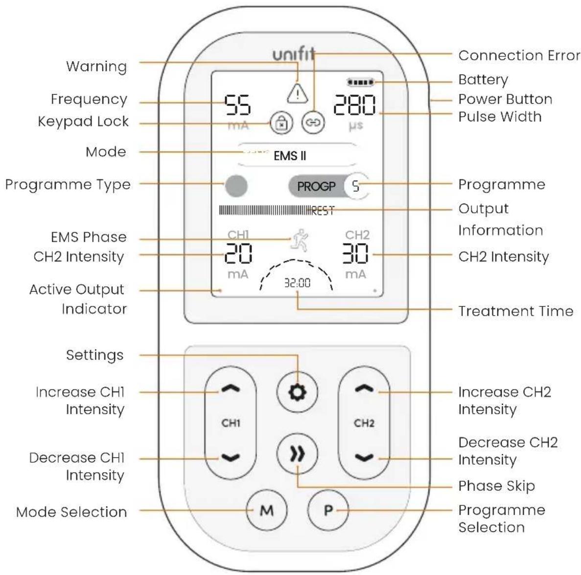
text_image
unifit Connection Error Battery Power Button Pulse Width 55 280 mA μs EMS II PROGP 5 Programme Output Information CH2 Intensity EMS Phase CH2 Intensity Active Output Indicator 32:00 Treatment Time Settings Increase CH1 Intensity CH1 CH2 Decrease CH2 Intensity Phase Skip Programme Selection Mode Selection M PPower
To turn the device on, press and hold the power button for 1 second.
To turn the device off, press and hold the power button for 3 seconds.
Channel Increase/Decrease
Increase and decrease the intensity of each channel using the increase and decrease buttons.
CHI ▲ CHI ▼ control the intensity of the left-hand lead/electrode pads.
CH2 ▲ CH2 ▼ control the intensity of the right-hand lead/electrode pads. Each press of the ▲ and ▼ buttons will adjust the intensity by 1mA. The intensity can be increased or decreased quickly by pressing and holding the ▲▼ buttons.
Mode
Press the mode selection button to switch between modes (TENS, EMS I, EMS II, EMS III EMS III or Massage).
Programme
Press the programme to change the selected programme.
Settings
Press the settings button to change the settings of selected programmes. See full directions for changing settings in section 6.
Phase Skip
In EMS programmes, press phase skip button to skip to the next phase of the programme.
Lock / Unlock
If no key is pressed for 30 seconds, Unifit will auto-lock. To unlock the keypad, press either CH1- or CH2-.
Keypad Lock Icon
When the keypad is locked, the icon will be displayed. If the icon is flashing,

this means a button has been pressed whilst the device is locked.
Warning Icon
The warning icon will flash in EMS
manual programmes if the Rest period is less than Rest Time=Work Time ^+ (WorkHz-16.66)/16.66 seconds.
Connection Error Icon
If the device is incorrectly connected to the body, this the connection error icon will flash.
06. Directions for Use
Connecting the Lead Wires and Pads
- Insert the lead wire plug into the base of the unit.
- Attaching the electrode pads to the lead wire. Push the pin ends firmly into the pigtail ends of the electrode pads.
- Before applying the electrode pads to your body, make sure your skin is clean and dry.
- Place the electrode pads on the skin (see Pad Placement).

Warning: Ensure Unifit is switched off before applying the electrode
pads on the skin.
Turning Unifit On
To turn the unit on, press the Power button on the side of the device for approximately 1 second until the display shows. The unit will start with the programme you used last.
Unifit will automatically turn off if both strength controls are set to zero for 5 minutes.
Mode and Programme Selection
-
Press the mode selection button to scroll through and select the desired mode.
-
Once you have selected the mode, press the programme selection button to scroll through and select the programme of choice.
Each time you change the mode or programme, the intensity level will revert to zero. This is a safety feature to alleviate any sudden feeling of a surge, as each programme gives a different sensation.
Selecting Treatment Time
The default treatime time for preset programmes is shown. For relevant programmes, treatment time can be changed by pressing the settings button. Use CH2▲▼ to select the preferred treatment time. You can select between 5 - 90 minutes or continuous (marked as C).
Setting the Intensity
Once the electrode pads have been connected and applied to the body and the programme has been selected, the intensity levels can be adjusted. Unifit has 99 levels of intensity.
CH1▲ CH1▼ control the intensity of the left-hand lead/electrode pads. CH2▲ CH2▼ control the intensity of the right-hand lead/electrode pads. Each press of the ▲ and ▼ buttons will adjust the intensity by 1mA. The intensity can be increased or decreased quickly by pressing and holding the ▲▼ buttons.
At low intensity levels, it is common for no sensation to be felt. Continue to increase the intensity until the sensation is strong but comfortable.
During a session, your body can become used to the sensation. If this is the case, increase the intensity levels.
The intensity controls will not operate unless the Unifit has been properly conenected to the body. If the Unifit detects a disconnection on either channel, the intensity will rest to 0mA and the connection error icon will flash. This is a safety feature designed to prevent sudden surges in stimulation.
When an orange circle is displayed next to the intensity levels, this means the output is high enough be harmful if not used correctly. Please use with caution.
Manual Setting Selection
In most cases, the programmes settings are preset. These programmes are identified by 'P'. When a programme has manual settings available, 'M' will be displayed.
In these programmes you are able to select and change the following parameters:
Frequency (Hz)
Pulse Width ( s)
Treatment Time (min)
Work Time (EMS programmes only) (s)
Rest Time (EMS programmes only) (s)

Note: Treatment time can be adjusted for all TENS programmes.
-
To adjust the settings of a programme, press the settings button.
-
Use the CH1▲▼ buttons to cycle
between the different settings you wish to change. The selected setting will flash.
-
Use CH2▲▼ to increase or decrease these settings.
-
To confirm your manual settings, press the settings button again. Alternatively, the device will automatically confirm your settings if no button is pressed for 5 seconds.
Warning: In the EMS manual programmes a warning triangle will be displayed if the Rest period is less than Rest Time=Work Time*(WorkHz-16.66)/16.66 seconds
Programme settings can be reset by pressing the mode and programme buttons simultaneously.
Completing a Session
Once you have correctly connected the device, electrode pads, selected the mode, programme and intensity, the treatment session will be underway.

Note: If the sensation becomes uncomfortable, reduce the
intensity
The session will run for the selected treatment time.
After Your Session
Should you wish to start a new session select mode, programme and intensity as before.
To turn the Unifit off at any stage, press
and hold the power button for 3 - 5 seconds.
After the session is complete and Unifit is switched off, remove the electrode pads from your skin by holding the electrode pad itself and gently pulling. Do not pull on the lead wires or the pigtail wire of the electrode pad.
Replace the electrode pads to their protective plastic shield and return them to the re-sealable plastic bag. Ensure the bag is sealed.
Usage Memory
To view the usage memory, press and hold the settings and phase skip buttons for 3 seconds.
To return to the home screen, press and hold the settings and phase skp buttons for 1 second.
The device memory can be reset by holding the mode and programme buttons simultaneously for 3 seconds. This can only be done whilst viewing the memory screen.
07. TENS
Programmes
Transcutaneous Electrical Nerve Stimulation provides a natural solution to pain relief in one of two ways:
- Pain Gate
Stimulates sensory nerves to block pain signals from being received from the brain.
Pain Gate Stim provides pain relief whilst being used.
• Endorphin Release
Low frequency TENS promotes the release of endorphins, the body's natural pain killer.
Endorphin Release builds up over 40 minutes and will last several hours after stimulation is ended.
- Programme Selection
There is not one programme for a particular condition, and the best choice varies from each person, even if they have the same type of pain. The "Recommended Use" are suggestions to help with programme selection. However, each user needs to select both the programme and the positioning of the electrode pads that is best for them.
- Intensity Selection
The stimulation sensation should be strong but comfortable. Further increases during use may be necessary if your body becomes used to the sensation.
- Frequency of Use
TENS can be used for as long as it is necessary. Continuous treatment is safe, but electrode pads should be repositioned regularly (at least every 12 hours) to allow the skin to be exposed to the air.
The Endorphin Release programmes work best when the strength is high enough to cause small muscle contractions. Best results are achieved with a session duration between 20 and 40 minutes. Longer use may cause muscle ache.
| Prog | Type of Relief | Sensation | Recommended Use |
| 1 Pain Gate | Smooth, constant sensation | For first use of TENS. These programmes have slightly different parameters so choose the one that works best for you. | |
| 2 Pain Gate | Smooth, constant sensation | ||
| 3 Endorphin Tapping | For chronic pains such as back pain and arthritis | ||
| 4 | Pain Gate + Endorphin | Pulsing | For radiating pain in arms and legs and deep muscular pain (Osteoarthritic pain in the knee, Sciatica central pain). These programmes have slightly different parameters so choose the one that works best for you. |
| 5 | Pain Gate + Endorphin | Pulsing | |
| 6 | Pain Gate + Endorphin | Alternating tapping / constant | For maximum production of the two central opioid peptides associated with pain relief. These programmes have slightly different parameters so choose the one that works best for you. |
| 7 | Pain Gate + Endorphin | Alternating tapping / constant | |
| 8 | Pain Gate + Endorphin | Relaxing message sensation | Settings modulate to prevent accomodation occurring. |
| 9 | Pain Gate + Endorphin | Relaxing message sensation | Settings and intensity modulate to prevent accomodation occurring. |
| 10 Pain Gate | Smooth, constant sensation | Treating nerve rich areas (e.g. facial pain, neck pain) | |
| 11 | Pain Gate or Endorphin | Constant sensation | For manual settings control. |
| 12 | Pain Gate +/or Endorphin | Pulsing | |
For full programme parameters, please see section 18 Specification
08. EMS Programmes
Before selecting an EMS programme, you will need to select an EMS Mode:
EMS I
For small muscles such as those in the hands.
EMS II
For medium sized muscles such as arms and feet.
EMS III
For large muscles such as thighs, buttocks and abdomen.
EMS III
Advanced muscle mass mode for large muscle mass.
With the mode selected, please choose from one of the following programmes.
| Prog Application Description | ||
| 1 | Muscle Calming | Relax the muscles as much as possible and to promote the body's natural endorphins to promote pain relief and to improve the blood circulation and provide oxygen into the muscle. |
| 2 | Resume Training | Promotes slow twitch fibres to build muscle strength to help reduce muscle atrophy ready for resuming training activities. |
| 3 | Resume Training | Progress from programme 2 as tolerance increases. |
| 4 | Resistance Training | Improving the capacity to develop very high level of muscle force over a long period of time. Improving the efficacy of oxygen consumption at the muscle level and the capacity to withstand toxin accretion, such as lactic acid. For sports activities that require very high levels of prolonged muscle activity: Rowing, Cycling, Middle distance running. |
| 5 | Resistance Training | Progress from programme 4 as tolerance increases. Alternative application: Lipolysis Increasing blood circulation and modifying the metabolism of the lipocytes. This helps to stimulate the subcutaneous deposits of fat, reducing or eliminating the 'Orange Peel' effect of the skin surface |
| 6 | Maximum Muscle Contraction | To increase muscle bulk and volume and to improve muscle force. Searching for muscular hypertrophy. |
| 7 | Muscle Toning | Strengthening the muscles, improving blood circulation and capillary bed density. Ideal for applying to the Thigh, Legs, Bottom and Abdomen. |
| 8 | Muscle Toning | Similar to programme 7, but adding bulk in preference to endurance |
| 9 | Force Output, Anaerobic Activity | Increasing the muscle capacity to a level of instantaneous maximum muscle force, changing muscle force into explosive action. Used for all activities requiring maximum muscle output in a very short space of time, such as Judo, short distance sprinting, throwing the discus or shot-put. |
| 10 Manual | Select the frequency, the pulse width, the work and active rest time. At first use, the default values are shown. Note: There are two manual programmes as the device will remember your previously selected settings. This allows you to create two custom programmes. | |
| 11 Manual | ||
For full programme parameters, please see section 18 Specification
Work / Rest Selection
When selecting work and rest times for manual programmes, the Warning triangle is displayed if the Active Rest period is less than:
Rest Time = Work Time * (WorkHz-16.66) / 16.66 seconds.
This is because muscle fibres can only activate a limited number of times a minute (about 1000) without becoming fatigued.

Warning: Consult your healthcare professional before altering these settings. Correct settings depend on your muscle tone and exercise goals. Inappropriate settings could cause discomfort, undesired muscle balance, or even muscle injury.
Intensity Selection
The aim of EMS is to produce powerful, visible muscle contractions. The intensity should be increased to roughy 3x the level at which you can first feel tingling, or to as high as you can stand without causing pain.
Use a low intensity for the first session to help you to understand how the machine works.
Intensity should be increased throughout a session and gradually over time. This will help produce effective, pain-free contractions.
Combining Voluntary Activity
Voluntary muscular activity is more effective than stimulation, and it may improve progress if you combine voluntary contraction with stimulation. For best results, always try to contract voluntarily during the work phases.
Frequency of Use
Ideally, use EMS programmes once every two days for each muscle with a day of rest in between. It is possible to work on pairs of muscles, for example thighs and abdominal muscles, treating one set one day and the other the next day.
Regular use over a period of 4 – 6 weeks should give good initial results, depending on the body shaping, toning, sports training or rehabilitation and recovery needs.
Massage programmes can be used to relieve muscle stiffness. Experiment with the different programmes to find the one that you find the most relaxing.
Programme 1 alternates between two strong squeezing/kneading feelings.
Programme 2 alternates between slow and fast tapping.
Programme 3 alternates between gentle and strong kneading.
Programme 4 has five steps of gradually increasing strength of kneading, alternating with tapping.
Programme 5 & 7 alternates between slow and medium-strong tapping.
Programme 6 is a gentler form of programme 5.
Programme 8 is a pumping sensation roughly equivalent to your heart rate, that slowly increases in speed over the course of the 20 min treatment. It is especially effective with swollen legs and veins.
Programme 9 is squeezing/kneading in 6 steps of increasing intensity.
Programme 10 generates a tapping sensation, gradually speeding up, then slowing down.

Note: There are no restrictions to the frequency of use of massage
programmes.
10. Pad
Placement
TENS Pad Placement
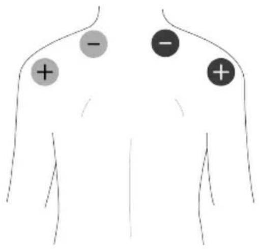
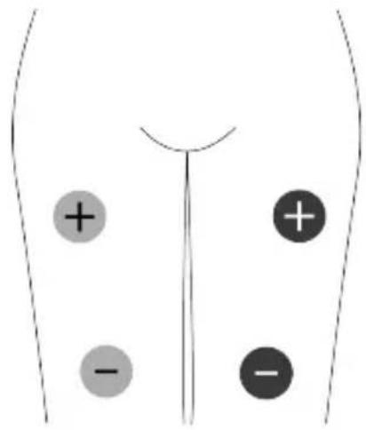
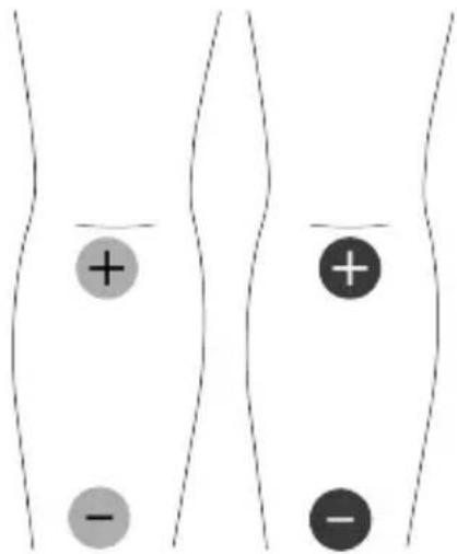
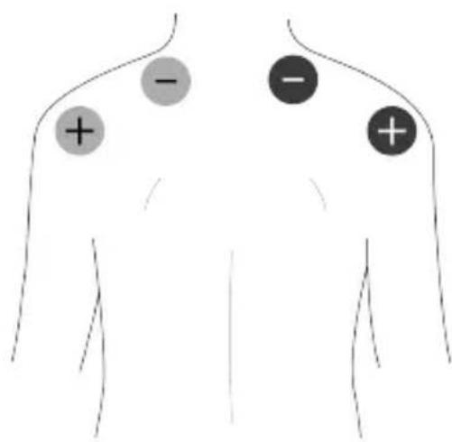
The easiest way is to apply the electrode pads around/near the source of the pain.
TENS activates the nerves best if it travels along the nerve rather than across it. So, place one pad further from the spine than the source of the pain, and one closer.
If the pain is in, or close to, your spine you can place one pad either side of the spine.

Note: See examples of positioning in the instructions enclosed with ads.
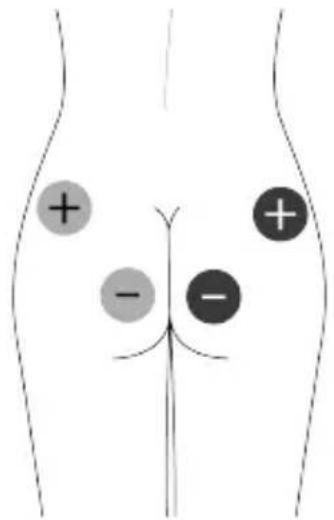
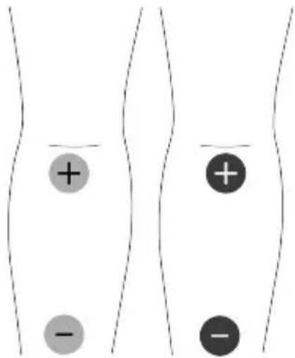
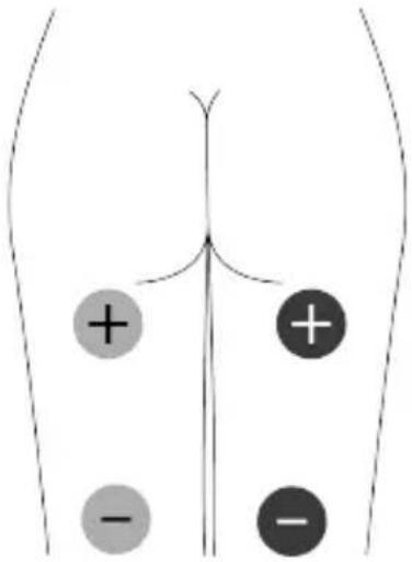
EMS Pad Placement
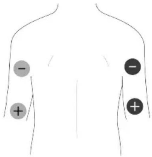
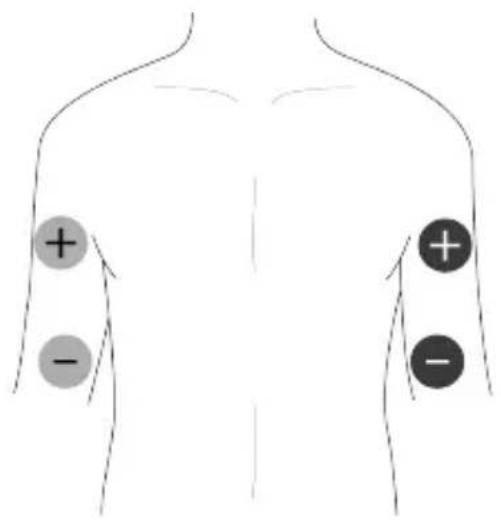
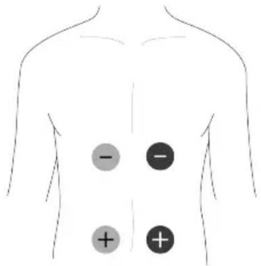
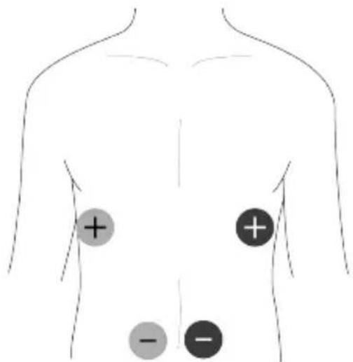
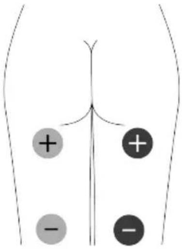
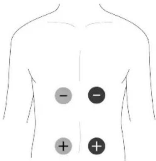
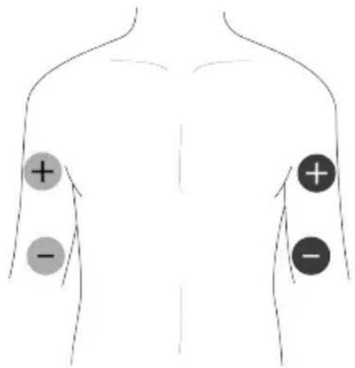
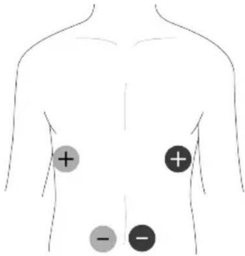
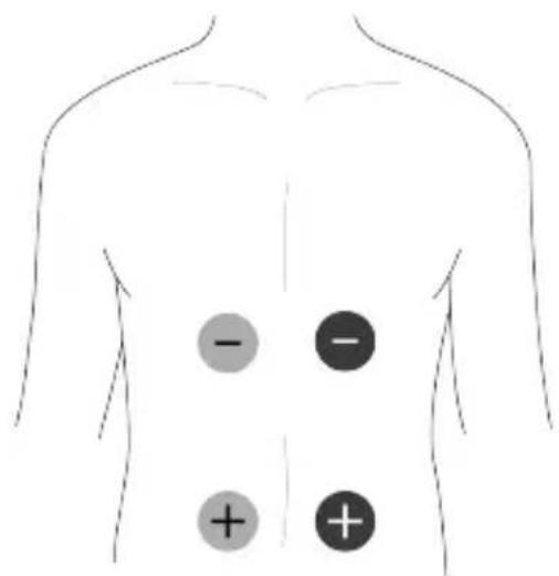
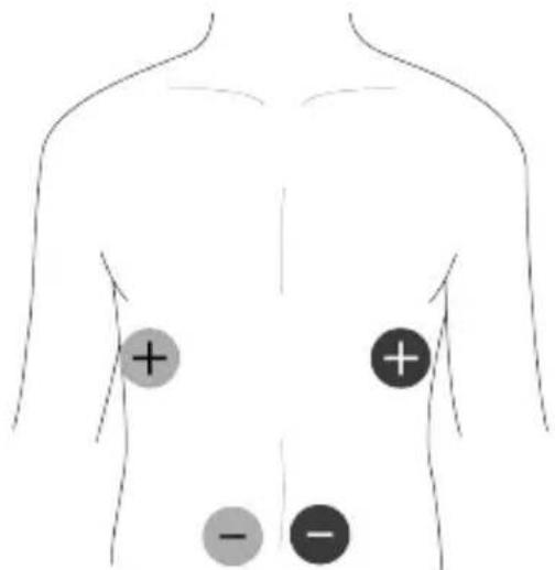
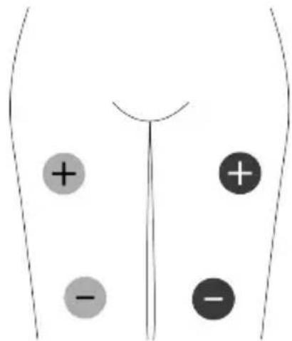
Electrode placement for EMS is important for obtaining the best results.
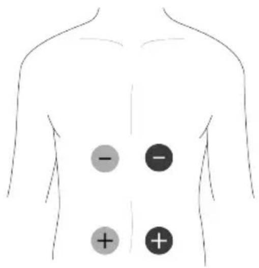
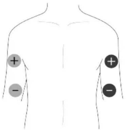
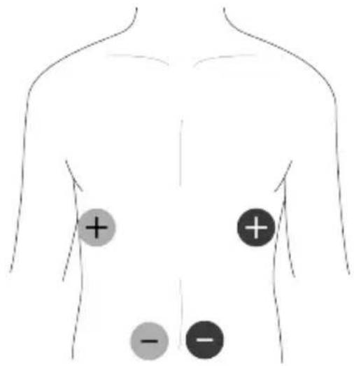
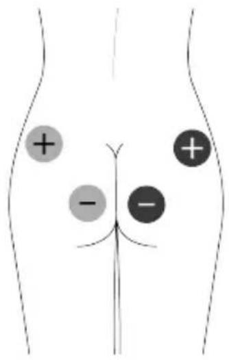
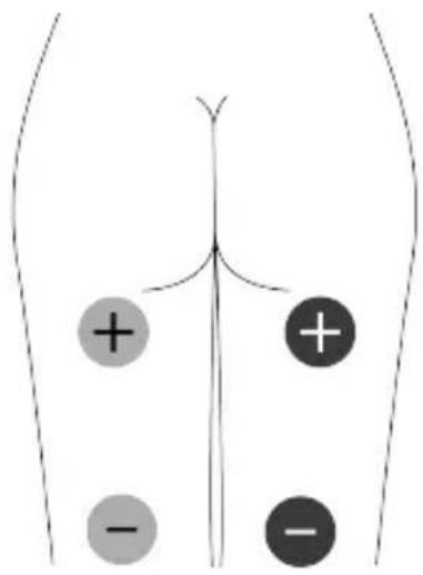
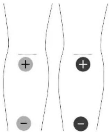
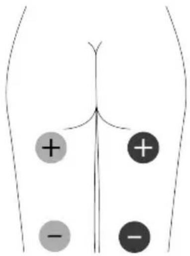
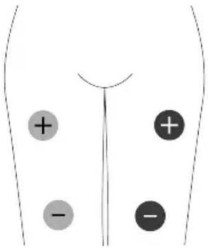
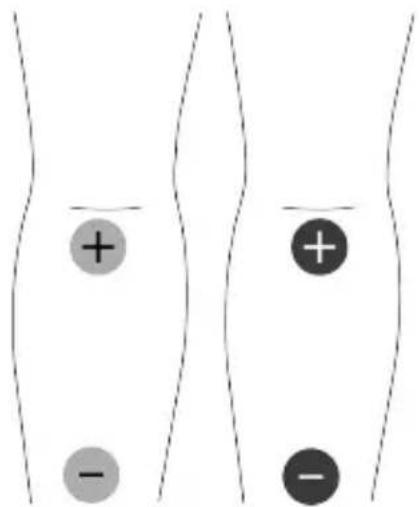
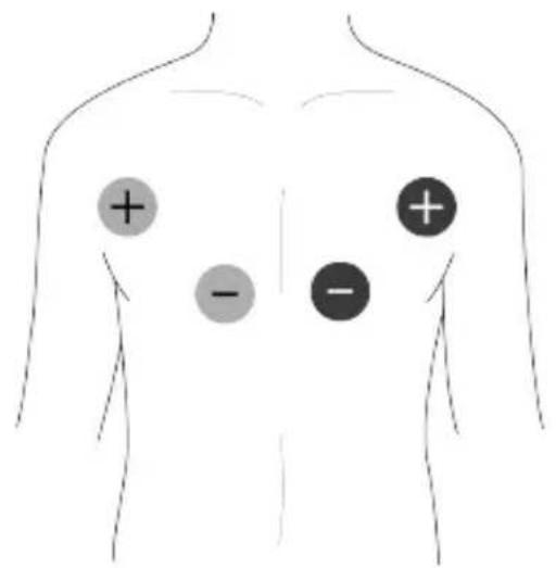
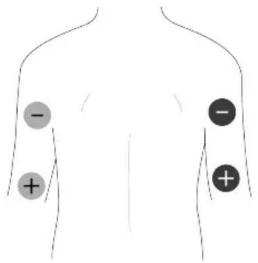
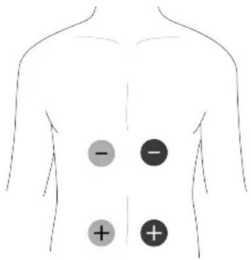
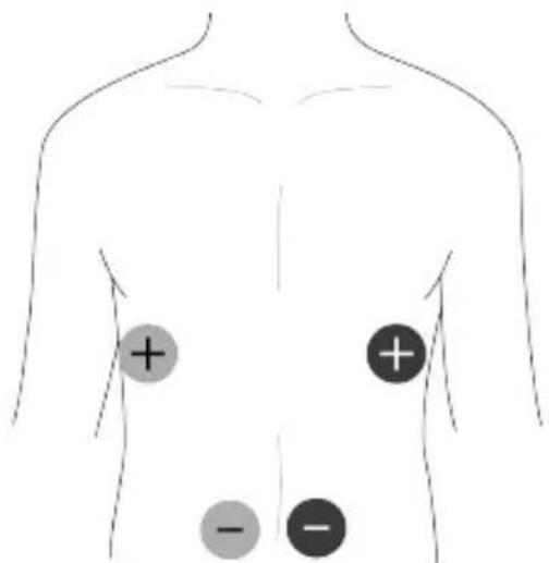
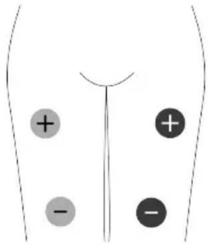
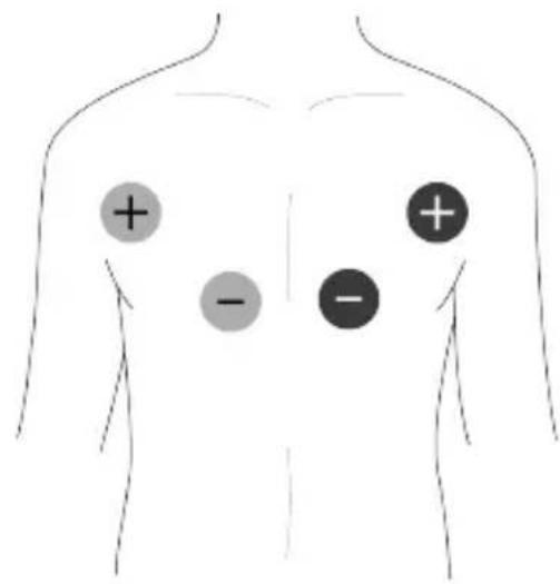
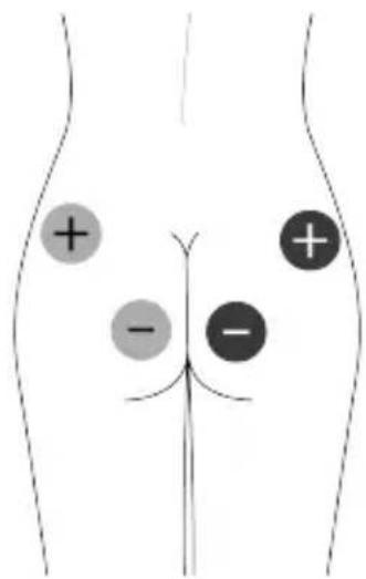
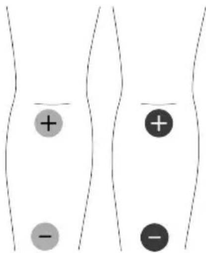
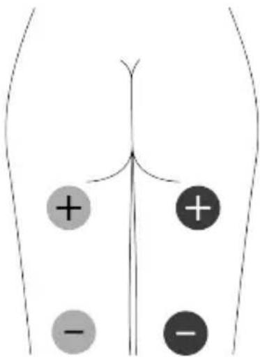
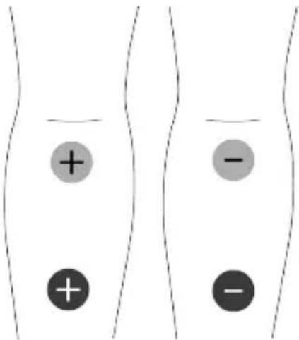
Place two electrode pads over the bulk of the muscle, with one electrode over the muscle's motor point. The motor point is the area on the skin that is located closest to the motor nerve's entry into the muscle – about 1/3 of the way down the muscle from the spine. Here, it is easiest to trigger a contraction by electrical stimulation.
Experiment by moving the electrode pads across the skin until you locate the point over the muscle that gives the cleanest contraction.

Note: The + electrode pad needs to be plugged in to the red lead
wire connector, the - pad to the black lead wire connector.
Chest
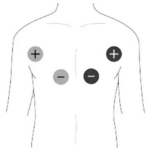
text_image
Diagram of human torso with four circular markers indicating positive and negative values, likely representing electrocardiogram measurements.Shoulders & Trapezius
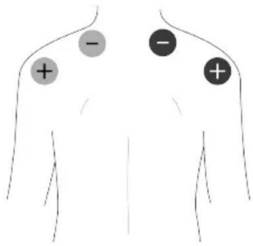
text_image
Diagram of human torso with labeled anatomical markers (+ and -) indicating regions of interest or measurement points.Triceps
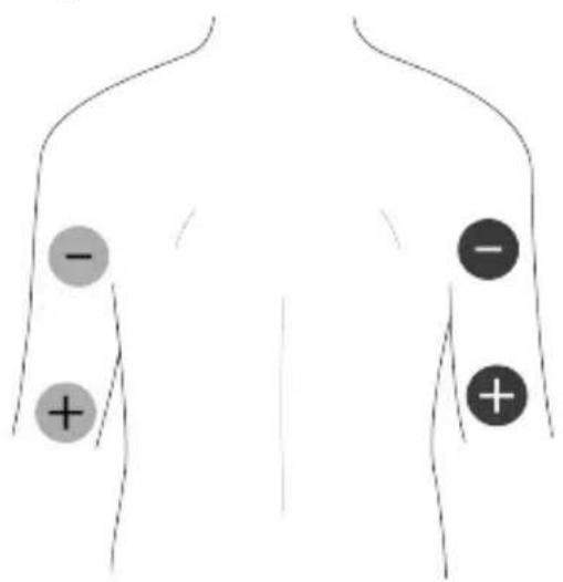
text_image
- - + + - +Abdominals
text_image
- - + + - +Biceps
text_image
Diagram of human torso with labeled anatomical regions marked by plus and minus signsAbdominals
text_image
Diagram of human torso with marked regions and plus/minus signs indicating areas of interestGlute
text_image
Diagram of human abdomen with labeled regions marked by plus and minus signsQuadriceps

text_image
Diagram showing a human torso with labeled charge symbols (+ and -) indicating positive and negative values.Hamstrings
text_image
Diagram showing a human torso with four labeled circular markers (+, -, -) indicating positive and negative values.Calves
text_image
Diagram showing charged particles (positive and negative) in a conductor, with plus and minus signs indicating charge distribution.Massage Pad Placement
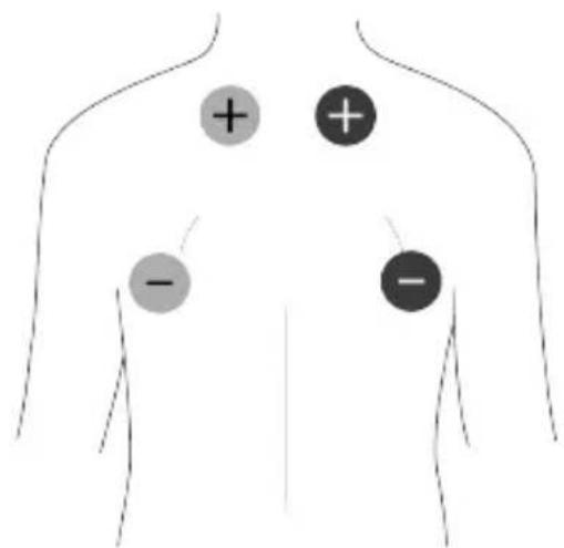
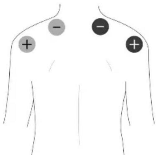
Massage mode can be used on any part of the body. However, the most commonly used applications can be seen in the following diagrams.
Neck & Tension Headache
text_image
Diagram of human torso with electrocardiogram (ECG) symbols indicating positive and negative values on the chestShoulders & Upper Back
text_image
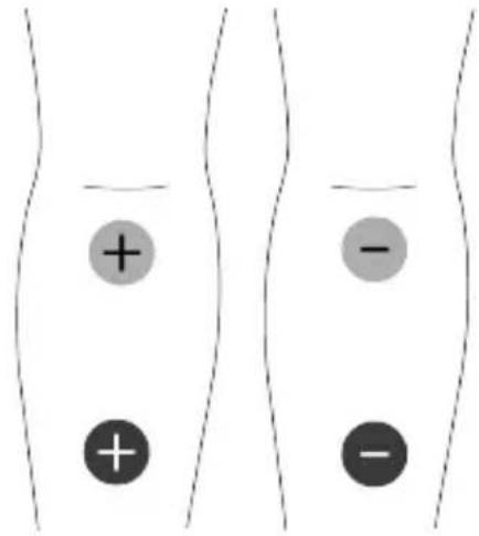
Diagram of human torso with labeled points and plus/minus signs indicating anatomical or measurement markersPoor return of blood to the heart is a common problem leading to swollen legs and varicose veins. Programme 8 helps to activate the venous pump. Waste products are discharged which in turn eases the flow of blood.
Circulation & Swollen Legs
text_image
Diagram showing positive and negative charges in two parallel conductors or wires, with plus and minus signs indicating charge distribution.Pad Advice
- The electrode pads supplied are reusable but for single patient use. The adhesive is a peelable hydrogel (water based).
• In order to obtain the best conductivity through the electrode pads always ensure that they are in good condition and tacky.
- Before use make sure your skin is clean and dry.
- Peel the electrode pads from their protective plastic shield by holding and lifting one corner of the pad and pulling. Do not pull on the pigtail wire of the pad.
• After use always replace the
electrode pads on the plastic liner and inside the re-sealable plastic bag.
- If the electrode pads dry out, it is recommended to buy a replacement pack. It is possible to restore some of the adhesion of the pad by adding a tiny drop of water on each pad and spreading around. If too much water is added, the electrode pad will become too soft. If that happens, place the electrodes sticky side up in a refrigerator for a few hours. This should help restore some adhesion.
- In very hot weather the gel on the electrode pads may become soft. In such cases place them, still on their plastic liners and in their re-sealable bag, into a fridge until they return to their normal condition.
- The electrode pads provided are latex-free.
- Replace the electrode pads when they lose their stickiness. Poor connection may cause discomfort and skin irritation.
- The electrode pads must always be used in pairs (two electrode pads on each channel), so that the signal can flow in a circuit.
- You may feel more sensation in one pad than the other. This is normal – it depends on where the electrode pads are in relation to your nerves.
11. Charging Unifit
Unifit is powered by a built-in rechargeable Li-ion battery. The battery should last at least 10 hours at 50mA, 300 s, 50Hz in TENS mode.
A charging adapter is included in the kit. It will take approximately 2 hours to fully charge the battery.
The battery status can be seen in the top right corner of the display. When the remaining battery life is below 20%, the battery icon will flash. Please charge your Unifit device at this stage.

Warning: Only use the charging adapter supplied. Use of other
chargers could be hazardous and will negate the warranty.
To charge the battery:
Connect the charger to the unit and plug it into a mains socket. A charging screen will be displayed, showing the battery percentage level. Charge the device until the battery level is 100%.

Note: The device should be charged at least once every 3
months to ensure the battery life is maintained.

Note: The device cannot be used while being charged.

Note: Charging voltage: DC 5V, charging current: 90mA.

Note: Charging adapter specifications:
• Output: DC 5 V; 1A
- Rated input voltage shall not
exceed 240 V
• Classification of protection against electric shock: Class II
• IP classification: at least IP21
- The adapter need to comply with IEC 60601-1 or IEC 60950-1

Battery Warnings
- This product is equipped with a Lithium-ion battery. Failure to follow these instructions could cause the lithium-ion battery to leak acid, become hot, explode or ignite and cause injury and /or damage:
- Do not pierce, open, disassemble, or use in a humid and/or corrosive environment.
- Do not expose to temperatures over 60^(140F) .
- Do not put, store or leave near sources of heat, in direct strong sunlight, in a high temperature location, in a pressurized container or in a microwave oven.
- Do not immerse in water or sea water, or get wet.
- Do not short-circuit.
- Do not transport and store the battery together with sharp metal objects that could pierce the battery. i.e. necklaces, hairpins, nail etc.
- Do not strike at pack with any sharp edge or throw the pack.
• To avoid the risk of electric shock,
this equipment must only be connected to a supply mains with a protective earth connection.
- Do not position the equipment during charging such that it is difficult to use the charging adapter. The provided charging adapter is used to isolate the equipment circuits from the mains power supply.
- Only use the battery charger provided for recharging batteries. Do not connect the pack to an electrical outlet.
- Keep batteries out of the reach of children to prevent them from swallowing them by mistake. If swallowed by child, contact your healthcare professional immediately.
- If battery leakage occurs and comes in contact with the skin or eyes, wash thoroughly with lots of water and immediately seek medical attention.

Battery Cautions
- Do not use in a location where there is a large amount of static electricity, otherwise, the safety devices in the battery pack may be compromised.
- If the battery pack creates an odour, generates heat, becomes discoloured or deformed, or in any way appear abnormal during use, recharging or storage, immediately remove it from the device or battery charge and stop using it.
- Disposal: Always dispose of batteries and device responsibly according to local government guidelines. Do not throw batteries onto a fire. Risk of explosion.
12. Cleaning & Storage
Clean the case and lead wires at least once a week by wiping with a damp cloth and a solution of mild soap and water. Wipe dry.
- Do not immerse your Unifit unit in water.
- Do not use any cleaning solution other than soap and water
Storage life of an unopened pack of electrode pads is 2 years. This may be affected by very high temperatures or very low humidity.
The unit has no fixed shelf life.
13. Replacement Parts
Expected Service Life
- The machine will often last for more than 5 years, but is warranted for 2 years. Accessories (lead wires, electrode pads, and batteries) are not covered by the warranty.
- Lead wire life depends greatly on use. Always handle the leads with care. We recommend to replace the lead wires regularly (about
every 6 months).
- Electrode pads should last 12 to 20 applications, depending on skin condition and humidity.
The following replacement parts may be ordered from your supplier or distributor (see back cover for contact details) or from TensCare at www.tenscare.co.uk or +44(0) 1372 723434.
| E-CM5050 | Square electrode pads (pack of 4) |
| E-CM50100 | Large electrode pads (pack of 4) |
| E-ULSTIM-X | Hypoallergenic electrode pads (pack of 4) |
| L-CPT Lead wire | |
| X-BX-UR Belt clip | |
| X-UNICH | Charging adaptor |
| X-MULTIPA-UK | UK socket |
| X-MULTIPA-EU | EU socket |
| X-MULTIPA-USA | US socket |
14. Warranty
This warranty refers to the unit only. It does not cover, electrode pads, charging adapter or the lead wires.
This product is warranted to be free from manufacturing defects for 2 years from date of purchase.
This warranty is void if the product is modified or altered, is subject to misuse or abuse; damaged in transit; lack of
responsible care; is dropped; if incorrect battery has been fitted; if the unit has been immersed in water; if damage occurs by reason of failure to follow the written instruction booklet enclosed; or if product repairs are carried out without authority from TensCare Ltd.
We will repair, or at our option replace free of charge, any parts necessary to correct material or workmanship, or replace the entire unit and return to you during the period of the warranty. Otherwise, we will quote for any repair which will be carried out on acceptance of our quotation. The benefits conferred by this warranty are in addition to all other rights and remedies in respect of the product, which the consumer has under the Consumer Protection Act 1987.
Our goods come with guarantees that cannot be excluded under the UK consumer Law. You are entitled to have the goods repaired or replaced if the goods fail to be of acceptable quality.
Before you send your unit for service
Before sending in your unit for service, please take a few minutes to do the following:
Read your manual and make sure you follow all the instructions.
Returning your unit for service
Should repair be needed within the warranty period, enclose the tear off section of the warranty card and your proof of purchase receipt. Please ensure all relevant details are completed before sending your unit in for service. Please ensure your contact details are still current and include a brief description
of the problem you are experiencing together with your purchase receipt.
Please return the unit and warranty card at your cost to:
TensCare Ltd
9 Blenheim Road,
Epsom, Surrey,
KT19 9BE, U.K.
Should you require any further information please do not hesitate to contact us by calling our number:
+44 (0) 1372 723 434.
15. Troubleshooting
If your Unifit is not working properly, please check the following:
Problem Possible causes Solution
No display Flat battery Charge battery. See section 11
| Damaged battery Contact supplier. There is no maintenance or calibration other than replacement of gel pads and battery charging. Do not modify the device as this may reduce safety or effectiveness. | ||
| Low battery display | Low batteries Charge battery | |
| Controls will not work | Keypad is locked If the lock icon is shown, press either of the - buttons to unlock the device. | |
| No sensation Intensity is not strong enough | Increase the intensity until you feel a strong but comfortable sensation. | |
| Intensity setting returns to 0mA. | There is a connection error leading to an open-circuit. | Ensure the pads are correctly attached to your body and lead wire inserted to both the pads and device. |
| Faulty pads or lead wires. | Try using the other lead wire or electrode pads. If problem occurs, it may be necessary to purchase replacements. | |
| Warning icon is flashing | EMS manual mode WORK/REST settings have been adjusted outside the recommended ratio. | Continue treatment with caution and stop if stimulation becomes uncomfortable.Manual programme settings can be reset by pressing and holding the mode and programme buttons simultaneously. |
If the above review has failed to resolve your problem, or to report unexpected operation or events, or to provide feedback call TensCare or your local supplier or distributor (address on back cover) for advice.
Contact TensCare customer service on +44 (0) 1372 723 434. Our staff are trained to assist you with most issues you may have experienced, without the need to send your product in for service.
European Medical Device Regulation requires that any serious incident that has occurred in relation to this device should be reported to the manufacturer and the competent authority in your country. This can be found at:
https://ec.europa.eu/docsroom/documents/36683/attachments/1/translations/en/renditions/pdf
16. EMC
Wireless communications equipment such as wireless home network devices, mobile phones, cordless telephones and their base stations, walkie-talkies can affect this equipment and should be used no closer than 30cm (12 inches) to any part of the device.
(Note. As indicated in 5.2.1.1(f) of IEC 60601-1-2:2014 for ME EQUIPMENT).

Note: For hospital use, full EMC advice tables are available on request.
17. Disposal of Electronic Products (WEEE)
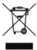
One of the provisions of the European Directive 2012/19/EU is that anything electrical or electronic should not be treated as domestic waste and simply thrown away. To remind you of this Directive all affected products are now being marked with a crossed-out wheelie bin symbol, as depicted below.
To comply with the Directive, you can return your old electro-therapy unit to us for disposal. Simply print a postage-paid PACKETPOST RETURNS label from our website www.tenscare.co.uk, attach this to an envelope or padded bag with the unit enclosed, and post it back to us. Upon receipt, we will process your old device for components recovery and recycling to help conserve the world's resources and minimise adverse effects on the environment.
18. Technical Specification
Programme Parameters
TENS Programmes:
| Prog | Preset / Manual | Frequency (Hz) | Pulse Width (μs) | Output | Prog time (min) |
| 1 | Preset | 80 | 150 | Constant | C |
| 2 | Preset | 100 | 200 | Constant | C |
| 3 | Preset | 2 | 250 | Constant | 30 |
| 4 | Preset | 100 (in 2 Hz burst) | 150 | Burst | 30 |
| 5 | Preset | 150 (in 2 Hz burst) | 200 | Burst | 30 |
| 6 | Preset | 2/80 | 200/100 | Han | 30 |
| 7 | Preset | 2/100 | 200/150 | Han | 30 |
| 8 | Preset | 10/100 | 250 | PFM | C |
| 9 | Preset | 2/120 | 200/100 | FM | C |
| 10 | Preset | 100 | 75 | DTENS | C |
| 11 | Manual | 2-150 | 50-300 | Constant | 5-90/C |
| 12 | Manual | 2-150 | 50-300 | Burst 2Hz | 5-90/C |
| Programme | Preset / Manual | Phase | Work | ||||||||||||||||||||||||||||||||||||||||||||||||||||||||||||||||||||||||||||||||||||||||||||||||||||||
| Time (s) | |||||||||||||||||||||||||||||||||||||||||||||||||||||||||||||||||||||||||||||||||||||||||||||||||||||||||
| Amplitude % | |||||||||||||||||||||||||||||||||||||||||||||||||||||||||||||||||||||||||||||||||||||||||||||||||||||||||
| Warm | 6 | 200 | 280 | 340 | 400 | 120 | 100 | 100 | 100 | 100 | 100 | 100 | 100 | 100 | 100 | 100 | 100 | 100 | 100 | 100 | 100 | 100 | 100 | 100 | 100 | 100 | 100 | 100 | 100 | 100 | 100 | 11 | 200 | 14 | 50 | 25 | 10 | 50 | 20 | 11 | 14 | 50 | 25 | 10 | 50 | 20 | 14 | 50 | 25 | 10 | 50 | 20 | 14 | 50 | 25 | 10 | 50 | 20 | 14 | 50 | 25 | 10 | 50 | 20 | 14 | 50 | 25 | 10 | 50 | 20 | 14 | 50 | 25 | 10 | 50 | 20 | 14 | 50 | 25 | ||||||||||||||||||||||||||
| Train | 10-120 | 100-400 | 1-30 | 80 | 100 | 100 | 100 | 100 | 100 | 100 | 100 | 100 | 100 | 100 | 100 | 100 | 100 | 100 | 100 | 100 | 100 | 100 | 100 | 100 | 100 | 100 | 100 | 100 | 120 | 100 | 100 | 100 | 100 | 100 | 100 | 100 | 100 | 100 | 100 | 100 | 100 | 100 | 100 | 100 | 100 | 100 | 100 | 100 | 100 | 100 | 100 | 100 | 20 | 10 | 50 | 20 | 14 | 50 | 25 | 10 | 50 | 20 | 14 | 50 | 25 | 10 | 50 | 20 | 14 | 50 | 25 | 10 | 50 | 20 | 14 | 50 | 25 | 10 | 50 | 20 | 14 | 50 | 25 | 10 | 50 | 20 | |||||||||||||||||||
| Train | 200 | 280 | 340 | 400 | 180 | 70 | 70 | 70 | 70 | 70 | 70 | 70 | 70 | 70 | 70 | 70 | 70 | 70 | 70 | 70 | 70 | 70 | 70 | 70 | 70 | 70 | 70 | 70 | 70 | 70 | 70 | 70 | 70 | 70 | 70 | 70 | 70 | 70 | 75 | 20 | 14 | 50 | 20 | 14 | 50 | 25 | 10 | 50 | 20 | 14 | 50 | 25 | 10 | 50 | 20 | ||||||||||||||||||||||||||||||||||||||||||||||||||
| Train | 10-120 | 100-400 | 1-30 | 80 | 100 | 100 | 100 | 100 | 100 | 100 | 100 | 100 | 100 | 100 | 100 | 100 | 100 | 100 | |||||||||||||||||||||||||||||||||||||||||||||||||||||||||||||||||||||||||||||||||||||||
| Train | 200 | 280 | 340 | 400 | 180 | 70 | 70 | 70 | 70 | 70 | 70 | 70 | 70 | 70 | 70 | 70 | 70 | 70 | 70 | 70 | 70 | 70 | 70 | 70 | 70 | 70 | |||||||||||||||||||||||||||||||||||||||||||||||||||||||||||||||||||||||||||||||
Massage Programmes:
| Prog | Prog Time (min) | Phase | Phase Time (min) | 1 | 2 | Output | ||
| Frequency (Hz) | Pulse Width (μs) | Frequency (Hz) | Pulse Width (μs) | |||||
| 1 | 30 | 1 | 30 | 85 | 200 | 135 | 100 | Burst |
| 2 | 30 | 1 | 2 | 1 | 200 | 15 | 200 | Burst |
| 3 | 30 | 1 | 2 | 25 | 200 | 80 | 200 | Burst |
| 4 40 | 1 | 4 | 1 | 250 | 4 | 250 | FM | |
| 2 | 6 | 20 | 250 | - | - | IM | ||
| 3 | 4 | 250 | ||||||
| 4 | 4 | 1 | 250 | 4 | 250 | FM | ||
| 5 | 6 | 30 250 | - | - | IM | |||
| 6 | 4 | 250 | ||||||
| 7 | 4 | 1 | 250 | 8 | 250 | FM | ||
| 8 | 6 | 40 250 | - | - | IM | |||
| 9 | 4 | 250 | ||||||
| 10 | 4 | 1 | 250 | 8 | 250 | FM | ||
| 11 | 6 | 50 250 | - | - | IM | |||
| 12 | 4 | 250 | ||||||
| 5 30 | 1 | 30 | 5 | 300 | - | - | Constant | |
| 2 | 8 | 300 | ||||||
| 6 30 | 1 | 30 | 5 | 200 | - | - | Constant | |
| 2 | 8 | 200 | ||||||
| 7 30 | 1 | 30 | 5 | 300 | - | - | Constant | |
| 2 | 8 | 300 | ||||||
| 8 20 | 1 | 5 | 250 | 25 | 250 | 250 | Burst 1Hz | |
| 2 | 5 | - | - | - | - | Burst 1.25 Hz | ||
| 3 | 5 | Burst 1.42 Hz | ||||||
| 4 | 5 | Burst 1.66 Hz | ||||||
| 9 30 | 1 | - | 25 200 | - | - | 2/2 | ||
| 2 | 30 | 200 | 2/2 | |||||
| 3 | 40 | 200 | 1/1 | |||||
| 4 | 50 | 200 | 1/1 | |||||
| 5 | 70 | 200 | 0.5/1 | |||||
| 6 | 80 | 200 | 0.5/1 | |||||
| 10 | 30 | 1 | - | 1 200 | - | - | 15 pulses | |
| 2 | 2 | 200 | 11 pulses | |||||
| 3 | 3 | 200 | 18 pulses | |||||
| 4 | 4 | 200 | 11 pulses | |||||
| 5 | 5 | 200 | 15 pulses | |||||
| 6 | 6 | 200 | 20 pulses | |||||
| 7 | 9 | 200 | 26 pulses | |||||
| 8 | 11 | 200 | 33 pulses | |||||
| 9 | 15 | 200 | 30 pulses | |||||
| 10 | 25 | 200 | 1 pulses | |||||
| 11 | 15 | 200 | 30 pulses | |||||
| 12 | 11 | 200 | 33 pulses | |||||
| 13 | 9 | 200 | 26 pulses | |||||
| 14 | 6 | 200 | 20 pulses | |||||
| 15 | 5 | 200 | 15 pulses | |||||
| 16 | 4 | 200 | 11 pulses | |||||
| 17 | 3 | 200 | 18 pulses | |||||
| 18 | 2 | 200 | 11 pulses | |||||
IM = Intensity Modulation, FM = Frequency Modulation, this programme constantly varies the stimulation
Device Specification
| Waveform Symmetrical rectangular bi-phasic | |
| Amplitude (over 1 kOhm load) 99 mA zero to peak in 99 steps +/- 10% | |
| Output Constant current 500-1000 Ohm | Constant voltage > 1000 Ohm |
| Max Pulse Energy Total output limited to 25 μC per pulse | |
| Output plug Fully shielded: touch proof | |
| Channels Dual channel | |
| Battery Built-in lithium-ion battery | Ratings: 1500mAh, 5.5Wh, 3.7V |
| Weight 128.5g | |
| Dimensions 125 x 62 x 26mm | |
| Safety Classification Internal power source | |
| Designed for continuous use | |
| No special moisture protection | |
| Software Version R2_00 | |
| Applied Part Skin surface electrode pads | |
| Environmental Specifications | |
| Operating Conditions Temperature range: 5 to 40°C | |
| Humidity: 15 to 90% RH non-condensing | |
| Atmospheric pressure: 700 hPa to 1060 hPa | |
| Storage Conditions Temperature range: -10-+60°C (≤ 1 month) | |
| -10-+45°C (≤ 3 month) | |
| -10-+28°C (≤ 1 year) | |
| Humidity: 15 to 75% RH non-condensing | |
| Atmospheric pressure: 700 hPa to 1060 hPa | |

Note: The electrical specifications are nominal and subject to variation from the listed values due to normal production tolerances of at least 5%.

Note: At least 30min required for the device to warm / cool from the minimum / maximum storage temperature between uses until it is ready for intended use.
Symbols Table

TYPE BF APPLIED PART: Equipment providing a degree of protection against electric shock, with isolated applied part. Indicates that this device has conductive contact with the end user.

This symbol on the unit means "Refer to instructions for use".

Temperature Limitation: indicates the temperature limits to which the medical device can be safely exposed.

Humidity Limitation: indicates the humidity limits to which the medical device can be safely exposed.

Atmospheric Pressure: indicates the atmospheric limits to which the medical device can be safely exposed.

Lot Number: indicates the manufacturer's batch code so that the batch or lot can be identified.

Serial Number: indicates the manufacturer's serial number so that a specific medical device can be identified.

Catalogue Number: indicates the manufacturer's catalogue number so that the device can be identified.

Do not dispose in household waste.

Manufacturer Symbol

Date of Manufacture: indicates the date which the medical device was manufactured. This is included within the serial number found on the device (usually on the back of the device), either as "E/Year/Number" (YY/123456) or "E/Month/Year/Number" (MM/YY/123456).

CE Mark

Medical Device

This medical device is indicated for home use.

Importer Symbol
IP22
This medical device is not water resistant and should be protected from liquids.
The first number 2: Protected against access to hazardous parts with a finger, and the jointed test finger of 12 mm ø, 80 mm length, shall have adequate clearance from hazardous parts, and protected against solid foreign objects of 12.5 mm ø and greater.
The second number 2: Protected against vertically falling water drops when enclosure is tilted up to 15^ . Vertically falling drops shall have no harmful effects when the enclosure is tilted at any angle up to 15^ on either side of the vertical.

Notes are used to provide clarification or recommendation.

A Warning is used when failure to follow the instructions may result in serious injury or death.

A Caution is used when failure to follow the instructions may result in a minor or moderate injury, or damage to the device or other property.

A Contraindication is used when a device should not be used because the risk of use clearly outweighs any foreseeable benefits and may result in serious injury or death.
Warranty Card
RETURN THIS PORTION ONLY WHEN YOU RETURN YOUR PRODUCT FOR REPAIR UNDER WARRANTY
Name:
Address:
Postcode:
Telephone:
E-Mail:
Model:
Date of Purchase:
ATTACH PROOF OF PURCHASE DO NOT SEND IN LEADS OR ELECTRODE PADS
Retailer's Name:
Retailer's Address:
Retailer's Postcode:
Brief description of the problem you are experiencing:
WARRANTY IS VOID UNLESS THE ABOVE INFORMATION IS COMPLETED AND CORRECT
Estimado cliente,
natural_image
Simple line drawing of a mobile phone with keypad and buttons (no text or symbols)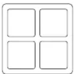
natural_image
Simple geometric diagram of four empty squares arranged in a 2x2 grid within a rounded square frame (no text or symbols)84x1
natural_image
Simple line drawing of a plug with four pins and a connector (no text or symbols)
text_image
Diagram of human torso with four circular markers indicating positive and negative values, likely representing electrocardiogram measurements.Hombros y Trapecio
text_image
Diagram of human torso with labeled regions marked by plus signs and minus signsTríceps
text_image
- - + +Glúteos

text_image
Diagram of human abdomen with labeled regions marked by plus and minus signsBíceps
text_image
Diagram of human torso with labeled anatomical regions marked by plus and minus signsAbdominales
text_image
- - + + - +Abdominales
text_image
Diagram of human torso with labeled regions marked by plus and minus signsIsquiotibiales
text_image
Diagram of human torso with labeled charge symbols (+, -) and shaded regions indicating areas of interestCuadríceps
text_image
Diagram showing a human torso with labeled regions marked by plus and minus signs, likely indicating areas of interest or measurement.Pantorrillas
text_image
Diagram showing charged particles (positive and negative) in a conductor, with plus and minus signs indicating charge distribution.text_image
Diagram of human torso with three marked electrical or electrocardiogram symbols (+, -, -) indicating positive and negative values respectively.text_image
Diagram of human torso with labeled anatomical markers (+ and -) indicating regions of interest or measurement points.text_image
Diagram showing two parallel conductive wires with positive and negative charge symbols, likely illustrating electrostatic induction or ion movement.TensCare Ltd, 9 Blenheim Road, Epsom, Surrey, KT19 9BE, UK
https://ec.europa.eu/docsroom/documents/36683/attachments/l/translations/en/renditions/pdf
16. EMC
IM = Intensity Modulation, FM = Frequency Modulation, this programme constantly varies the stimulation
natural_image
Simple line drawing of a mobile phone with buttons and a small circle on the right (no text or symbols)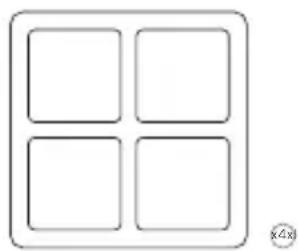
natural_image
Simple diagram of four empty squares arranged in a 2x2 grid within a rounded rectangle (no text or symbols)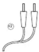
natural_image
Simple line drawing of a plug with four slots and a handle (no text or symbols)
text_image
Diagram of human torso with four marked electrical or diagnostic symbols: plus, minus, and circle.Les abdominaux
text_image
- - + + +Biceps
text_image
Diagram of human torso with three marked regions: positive, negative, and neutral signs on the chest.Les abdominaux
text_image
Diagram of human torso with labeled regions marked by plus and minus signstext_image
Diagram of human torso with labeled anatomical markers (+/-) indicating regions of interest or measurement points.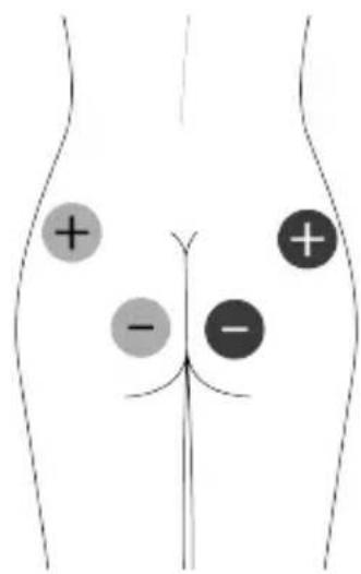
text_image
Diagram of human abdomen with labeled regions marked by plus and minus signsIschio-jambiers
text_image
+ + - -Quadriceps
text_image
Diagram showing a human torso with labeled charge symbols (+ and -) indicating positive and negative values.Mollets
text_image
Diagram showing two parallel lines with positive and negative charges marked by plus and minus signstext_image
Diagram of human torso with three marked electrical or electrocardiogram symbols (+, -, -) indicating positive and negative values.text_image
Diagram of human torso with labeled regions marked by plus signs and minus signstext_image
Diagram showing two parallel conductive wires with positive and negative charges, each marked with a plus sign and a minus sign.https://ec.europa.eu/docsroom/documents/36683/attachments/1/translations/en/renditions/pdf
16. EMC
natural_image
Line drawing of a mobile phone with front panel, keypad, and buttons (no text or symbols)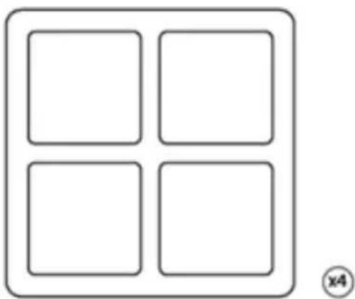
natural_image
Simple diagram of four empty rounded squares arranged in a 2x4 layout within a rounded rectangle (no text or symbols)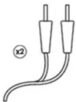
natural_image
Simple line drawing of two cables with two connectors, labeled 'x2' (no text or symbols on the cables themselves)
natural_image
Simple line drawing of a plug with a handle and two slots, labeled (x1) at bottom left (no text or symbols on the diagram itself)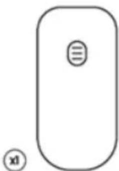
natural_image
Simple line drawing of a computer mouse with a button labeled '三' and an icon below (no text or symbols on the mouse itself)text_image
Diagram of human torso with three marked electrical or diagnostic symbols (+, -) indicating positive and negative values on the chest.Brust
text_image
Diagram of human torso with four circular markers indicating positive and negative values, likely representing electrocardiogram measurements.text_image
Diagram of human torso with labeled anatomical markers (+ and -) indicating regions of interest or measurement points.Trizeps
text_image
- - + + - +Bauch
text_image
- - + +Bauch
text_image
Diagram of human torso with labeled regions marked by plus and minus signsKniesehnen
text_image
Diagram showing a human torso with labeled regions marked by plus and minus signs, likely indicating areas of interest or measurement.Gesäss
text_image
Diagram of human abdomen with labeled regions marked by plus and minus signsQuadrizeps
text_image
Diagram showing charged particles (positive and negative) in a conductor, with plus and minus signs indicating charge distribution.Waden
text_image
Diagram of human torso with labeled charge symbols (+, -) indicating positive and negative valuestext_image
Diagram of human torso with three electrocardiogram buttons labeled +, -, and -text_image
Diagram showing charged particles (positive and negative) in a conductor, with plus and minus signs indicating charge distribution.text_image
Diagram of human torso with labeled pressure points (+) and - on chest, indicating blood pressure or measurement points.Pad Beratung
https://ec.europa.eu/docsroom/documents/36683/attachments/1/translations/en/renditions/pdf
16. EMC
natural_image
Line drawing of a mobile phone with front panel, keypad, and buttons (no text or symbols)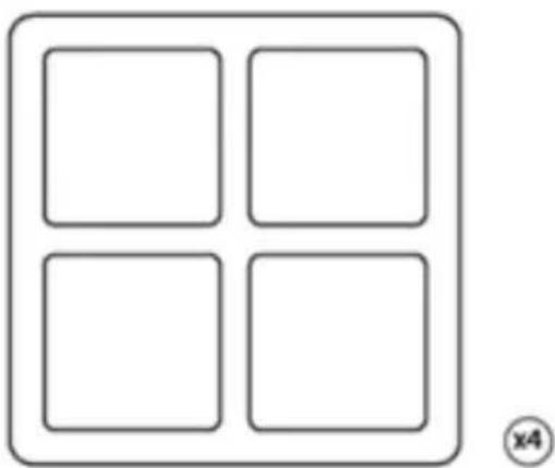
natural_image
Simple diagram of four empty rounded squares arranged in a 2x4 layout within a rounded rectangle (no text or symbols)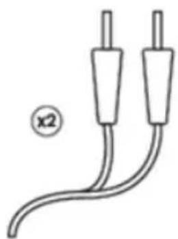
natural_image
Simple line drawing of two cables with two connectors, no text or symbols present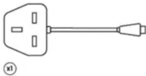
natural_image
Simple line drawing of a plug with a handle and two slots, labeled (x1) at bottom left (no text or symbols on the diagram itself)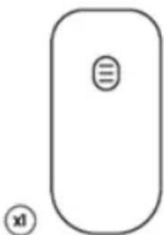
natural_image
Simple line drawing of a computer mouse with a button labeled '三' and an icon below (no text or symbols on the mouse itself)text_image
Diagram of human torso with three marked electrical or diagnostic points: positive, negative, and neutral signs.Petto
text_image
Diagram of human torso with four circular markers indicating positive and negative values, marked with plus and minus signs.Spalle e trapezio
text_image
Diagram of human torso with labeled buttons (+/-) indicating medical or diagnostic points on the chest areaTricipiti

text_image
- - + + - +Addominali
text_image
- - + +Addominali
text_image
Diagram of human torso with labeled regions marked by plus and minus signsQuadricipiti
text_image
Diagram showing a human torso with labeled regions marked by plus and minus signs, likely indicating areas of interest or measurement.Glutei
text_image
Diagram of human abdomen with labeled regions marked by plus and minus signsPolpacci
text_image
Diagram showing two parallel lines with positive and negative charges marked by plus and minus signsFemorali
text_image
Diagram showing a human torso with four labeled circular markers (+, -, -) indicating positive and negative charge states.text_image
Diagram of human torso with three electrocardiogram buttons labeled +, -, and -Shoulders & Upper Back

text_image
Diagram of human torso with labeled anatomical markers (+ and -) indicating regions of interest or measurement points.Circulation & Swollen LegsPosizio
text_image
Diagram showing charged particles (positive and negative) in a fluid container with labeled charge symbols (+)Consigli per il pad
https://ec.europa.eu/docsroom/documents/36683/attachments/l/translations/en/renditions/pdf
16. EMC
TensCare aim to give you the best possible product and service. We listen to your suggestions and are constantly trying to improve our products. We also want to learn about the way our products are used, and the benefits they give. If you have anything you would like to share with us, please get in touch.
www.tenscare.co.uk
Follow us:

@tenscareltd

TensCare Ltd

@TensCareLtd

TensCare Limited
CE
2797
EC Declaration of Conformity
Tenscare Ltd herewith declare that the product meets the provisions of REGULATION (EU) 2017/745 which apply to it. The medical device has been assigned to class IIa according to Annex IV of the REGULATION (EU) 2017/745. The product concerned has been designed and manufactured under a quality management system according to Annex IX, of REGULATION (EU) 2017/745. This EU declaration of conformity is issued under the sole responsibility of the manufacturer. No “Common Specification” is applicable.
Distributed by:

TensCare Ltd. 9 Blenheim Rd, Epsom, Surrey, KT19 9BE, UK, +44 (0)1372 723 434

TensCare Europe BV. Juliana van Stolbergstraat 52, 1723LD Noord-Scharwoude, Netherlands
I-UNIFIT-ML [UK,ES,FR,DE,IT] Rev. 1.0 08/22
Advena Ltd. Tower Business Centre, 2nd Flr, Tower Street, Swatar, BKR 4013, Malta

Complies with Medical Device Regulation (EU) 2017/745.