
CrossTraining - Fitness Equipment COMPEX - Free user manual and instructions
Find the device manual for free CrossTraining COMPEX in PDF.

| Product Type | Electrical muscle stimulator (electrostimulator) |
| Brand | Compex |
| Model | CrossTraining |
| Number of channels | 4 independent and individually adjustable channels |
| Pulse shape | Constant rectangular current with compensated pulses |
| Maximum intensity | 120 mA |
| Pulse frequency | 1 to 150 Hz |
| Pulse amplitude | 60 to 400 µs |
| Power supply | Rechargeable NiMH battery 4.8 V / ≥1200 mAh |
| Charger | Ref. 6830xx (only) |
| Battery life | Varies according to program and intensity |
| Available programs | Endurance, Resistance, Strength, Explosive strength, Cross Training, Recovery, Massage, Pain relief |
| Main categories | Conditioning, Pain Management, Recovery-Massage |
| Screen | LCD with adjustable contrast and backlight (Auto, On, Off) |
| Maintenance | Clean with a soft cloth and an alcohol-based detergent without solvents |
| Safety | Class II medical device, type BF, latex-free; compliant with IEC 60601 |
| Included accessories | Stimulator, charger, 4 cables, 5x5 and 5x10 electrodes, placement poster, quick guide, warning leaflet, carrying case, battery, 4 retaining straps, protective cover |
| Operating conditions | Temperature: 0 to 40 °C; relative humidity: 30 to 75% |
| Storage/transport | Temperature: -20 to 45 °C; relative humidity max. 75% |
Frequently Asked Questions - CrossTraining COMPEX
User questions about CrossTraining COMPEX
0 question about this device. Answer the ones you know or ask your own.
Ask a new question about this device
Download the instructions for your Fitness Equipment in PDF format for free! Find your manual CrossTraining - COMPEX and take your electronic device back in hand. On this page are published all the documents necessary for the use of your device. CrossTraining by COMPEX.
USER MANUAL CrossTraining COMPEX
- Explanation of symbols 02
-
How does electrostimulation work? 03
-
Device function 05
Contents of kits and accessories 05
Device description 06
Battery insertion 07
Connection 07
Preliminary settings 08
Choosing a category 08
Selecting a programme 09
Adjusting stimulation intensities 09
Programme progression 10
End of a programme 11
Battery level and charging 11
- Troubleshooting 13
- Device maintenance 16
- Technical specifications 17
- EMC Table 19
It is strongly recommended to read these instructions and the contra-indications and safety measures carefully before using your stimulator.
1. EXPLANATION OF SYMBOLS
 | See the instructions |
 | The stimulator is a category II device with built-in power supply and type BF applied parts. |
 | Manufacturer's name and address and date of manufacture |
 | This device must be separated from household waste and sent to special collection facilities for recycling and recovery |
 | The stand-by button is multi-functional |
 | Protect from sunlight |
 | Store in a dry place |
 | This is an indication for protection against ingress of water and particulate matter. The mark IP20 on your unit means: your unit is protected against solid foreign objects of 12.5mm dia and greater. Not protected against water |
 | IP02 on the carrying case means: Protected from the ingress of water droplets from a shower of rain. |
 | Latex-free |
 | Reference number |
 | Batch number |
2. HOW DOES ELECTROSTIMULATION WORK?
Electrostimulation involves stimulating nerve fibres by electrical impulses transmitted by electrodes. The electrical impulses produced by Compex stimulators are high-quality impulses that are safe, comfortable and effective and stimulate various types of nerve fibres:
- Motor nerves to stimulate a muscular response, referred to as electrical muscle stimulation (EMS).
- Certain types of sensitive nerve fibres to obtain analgesic effects or pain relief.
1. STIMULATION OF MOTOR NERVES (EMS)
With voluntary activity, the brain orders muscles to contract and a command is then sent to nerve fibres in the form of an electrical signal. This signal is then sent to muscle fibres, which contract. The principle of electrostimulation accurately reproduces the process involved in a voluntary contraction. The stimulator sends an electrical impulse to nerve fibres to excite them. This excitation is then transmitted to muscle fibres and results in a basic mechanical response (= a twitch). This is the basic requirement for muscular contraction. The muscular response is to all intents and purposes identical to the muscular work controlled by the brain. In other words, the muscle does not distinguish between a command sent by the brain or the stimulator.
Programme settings (number of impulses per second, duration of contraction, rest time, total programme duration) subject the muscle to various types of work, depending on the muscle fibre. Various types of muscle fibres can be identified according to their respective contraction speeds: slow, intermediate and fast fibres. A sprinter clearly has more fast fibres and a marathon runner has more slow fibres. With good knowledge of human physiology and full control of stimulation settings of the various programmes, muscular work can be specifically pinpointed to achieve the desired objective (muscular strengthening, increased blood circulation, firming, etc.).
2. STIMULATION OF SENSORY NERVES
Electrical impulses can also excite sensory nerve fibres to obtain analgesic effects or pain relief. Stimulating tactile sensory nerve fibres blocks pain being transmitted to the nervous system. Stimulating another type of sensory fibre increases the production of endorphins and therefore reduces pain. With pain relief programmes, electrostimulation can be used to treat acute or chronic localised pain and muscle pain.
Caution: Do not use pain relief programmes for an extended period without medical advice.
BENEFITS OF ELECTROSTIMULATION
Electrostimulation is a very effective method for making muscles work:
- With a significant improvement in various muscular qualities
- With no cardiovascular or mental fatigue
- With limited stress exerted on joints and tendons. Electrostimulation thereby enables more muscular work than voluntary activity.
For optimum results, Compex recommends supplementing your electrostimulation sessions with other commitments, such as:
• Regular physical exercise
• A balanced and healthy diet
• A balanced lifestyle
3. DEVICE FUNCTION
CONTENTS OF KITS AND ACCESSORIES
| REF QTY | ||
| STIMULATOR 101096D 1 | ||
| CHARGER 6830XX 1 | ||
| SET OF 4 SNAP CABLES 001119 1 | ||
| BAG OF SMALL 5X5 ELECTRODES | 42215 1 | |
| BAG OF LARGE 5X10 ELECTRODES | 42216-4 1 | |
| ELECTRODE PLACEMENTS POSTER | 880312 880313 | 1 |
| QUICK START GUIDE 885626D 1 | ||
| WARNING LEAFLET M307816 1 | ||
| CARRY CASE 680029 1 | ||
| BATTERY PACK 94121X 1 | ||
| 4X ELASTIC STRAPS 6522058 1 | ||
| PROTECTING COVER 690003 1 |
Only use this device with cables, electrodes, battery, power adaptor and accessories recommended by Compex.
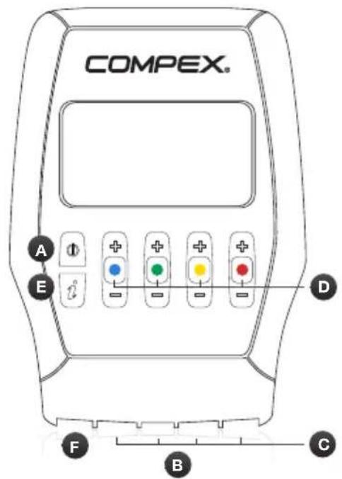
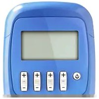
DEVICE DESCRIPTION
natural_image
Line drawing of a rectangular device with labeled ports H and G (no text or symbols beyond labels)A Standby button
B Sockets for the 4 stimulation cables
C Stimulation cables
D +/- buttons for the 4 stimulation channels
E I-button, which allows:
- The intensities to be increased on several channels at the same time
• The last 5 programmes used to be accessed
F Charger socket (slide the red cover to the right to reveal the charger connector)
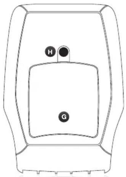
G Battery compartment
H Socket for belt clip
BATTERY INSERTION
Open the battery compartment cover and insert the battery, with the label pointing upwards so that the + and - terminals are opposite the device's contacts. Then replace the cover. If the device is not going to be used for over 3 months, ensure that the battery is fully charged. If the device is not going to be used for over 6 months, ensure that the battery is fully charged and remove it from the stimulator. Switch the stimulator off before removing the battery.
CONNECTIONS
CHARGER CONNECTION
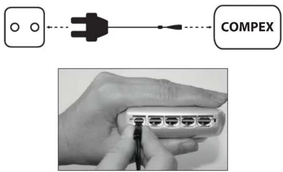
Remove all stimulation cables from the stimulator before recharging it. Connect the charger to a wall socket and connect the stimulator by sliding the red cover to the right to reveal the charger connector. It is strongly recommended to fully charge the battery before its first use to improve its performance and life span.
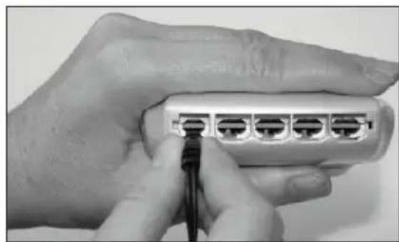
CONNECTING THE CABLES
The cables of the stimulator connect to the 4 sockets at the front of the device.
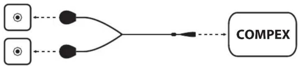
flowchart
graph LR
    A["Input 1"] --> C
    B["Input 2"] --> C
    C --> D
    D --> E["COMPEX"]
    style A fill:#fff,stroke:#000
    style B fill:#fff,stroke:#000
    style C fill:#000,stroke:#000
    style D fill:#fff,stroke:#000
    style E fill:#fff,stroke:#000
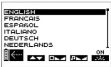
PRELIMINARY SETTINGS
Before your first use, you can define various settings. This options screen can then be displayed by switching the device off and by pressing and holding the on/off button for at least 2 seconds.
ABCDE
B Press the +/- button of channel 1 to select the language to be used.
C Press the +/- button of channel 2 to adjust screen contrast.
D Use the +/- button of channel 3 to adjust the volume.
E Press the +/- button of channel 4 to adjust the backlighting.
ON: backlighting always active.
OFF: backlighting always inactive.
AUTO: backlighting activated every time a button is pressed.
A Press the on/off button to confirm and save your selections. Settings are immediately applied.
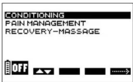
CHOOSING A CATEGORY
N.B. The following screens are generic examples but they work in the same way regardless of the device that you have.
To switch the stimulator on, briefly press the on/off button.
Before selecting a programme, you should select the desired category.
ABE
A Press the on/off button to switch the device off.
B Press the +/- button of channel 1 to select a category.
E Press the +/- button of channel 4 to confirm your selection.
TOP 5
To access the last 5 programmes used press the I-button. From there, select the desired programme and start it.
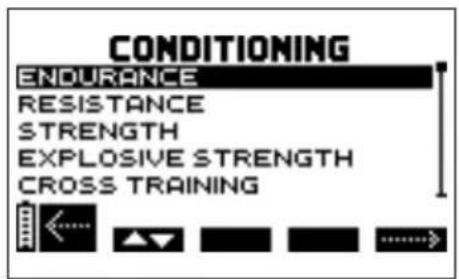
SELECTING A PROGRAMME
ABE
A Press the on/off button to return to the previous screen.
B Press the +/- button of channel 1 to select a programme.
E Press the +/- button of channel 4 to confirm the selection and start the stimulation session.
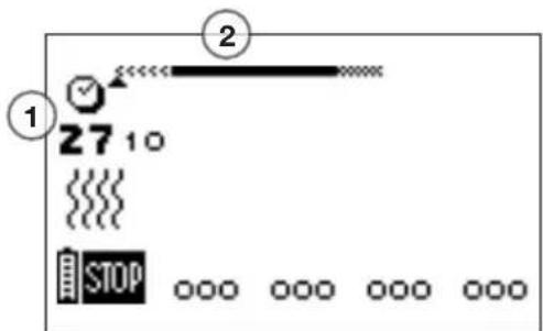
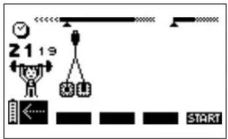
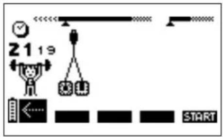
ADJUSTING STIMULATION INTENSITIES
When you start a programme, you are asked to increase the stimulation intensities.
This step is essential for a successful session.
ABCDE
1 Programme duration in minutes and seconds
2 Programme progression bar. For details of how it works, see the following paragraph:
"Programme progression"
A Press the on/off button to switch the unit into Pause mode.
B C D E The four channels flash, going from + to 000. The stimulation intensity must be increased to be able to start stimulation. For this, press the + buttons of the relevant channels until the desired setting is reached.
N.B. To increase the intensities on several channels simultaneously, press the I-button and then increase the intensities. The interdependent channels are displayed in white on a black background.
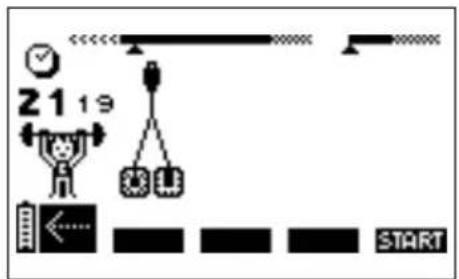
PROGRAMME PROGRESSION
Stimulation starts properly once the stimulation intensity has been increased.
The examples below explain the general rules. Depending on the programme, there may be slight differences.
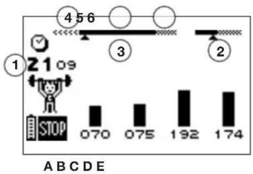
bar
| Label | Value | |---|---| | 1 | 2109 | | STOP | 070 | | 2 | 075 | | 3 | 192 | | 4 | 56 |1 Time remaining (in minutes and seconds) until the end of a programme
2 The duration bar showing the duration of the contraction and duration of active rest is only shown during the work sequence
3 Session sequences
4 Warm-up
5 Work period
6 Relaxation
A Press the on/off button to temporarily interrupt the programme. To resume, simply press the +/- button of channel 4. The session will resume at 80% of the intensity level being used before it was interrupted.
N.B. In pause mode, the button switches directly to the next sequence.
N.B. In pause mode and depending on the programme, usage statistics may be displayed:
MAX = the maximum intensity reached per channel during contraction phases
AVG= the average intensity for all channels applied during the contraction phases
B C D E The various intensities reached during the contraction phase are shown by a series of black vertical bars; the intensities of the rest phase are illustrated by hatched bars.
Please note that the stimulation intensities for the active rest phase are automatically set to 50% of the contraction intensities. They can be changed during the rest phase. Once changed, they are completely independent of the contraction intensities.
END OF A PROGRAMME
At the end of a session, the following screen is displayed. To stop the stimulator, press the on/off button.
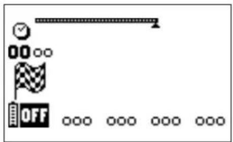
N.B. Depending on the programme, usage statistics may be displayed (see previous chapter "Programme progression").
BATTERY LEVEL AND CHARGING
Battery performance depends on the programme and the stimulation intensity applied. It is strongly recommended to fully charge the battery before its first use to improve its performance and life span. Always use the charger supplied by Compex to recharge the battery.
If the device is not going to be used for over 3 months, ensure that the battery is fully charged. If the device is not going to be used for over 6 months, ensure that the battery is fully charged and remove it from the stimulator. Switch the stimulator off before removing the battery.
BATTERY LEVEL
The battery charge level is shown by a battery icon in the bottom left of the screen. The battery icon flashes when the battery is completely flat. The device can then no longer be used. Recharge it immediately.
RECHARGING
Remove all stimulation cables from the stimulator before recharging it. Connect the charger to a wall socket and connect the stimulator by sliding the red cover to the right to reveal the charger connector.
The charging menu shown below appears automatically.

The charging duration is displayed on the screen. As soon as charging is complete, the battery flashes. Disconnect the charger: the stimulator will switch off automatically.
4. TROUBLESHOOTING
ELECTRODE FAULT
The device emits a tone and alternately displays the pair of electrodes symbol and an arrow pointing towards the channel on which a problem has been detected. In the above example, the stimulator has detected an error on channel 1.
Check that the electrodes are connected to this channel.
If electrodes are old, worn and/or if the contact is poor: try using new electrodes.
Try using the stimulation cable on a different channel. If the cable is still faulty, replace it: www.compex.info
STIMULATION DOES NOT PRODUCE THE USUAL SENSATION
Check that all settings are correct and check electrodes are properly positioned.
Change the position of the electrodes slightly.
STIMULATION CAUSES DISCOMFORT
Electrodes lose their adhesive capacity and no longer provide suitable contact with skin.
Electrodes are worn and must be replaced.
Change the position of the electrodes slightly.
THE STIMULATOR IS NOT WORKING
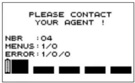
When an error screen is displayed during use, note the error number (in the example, the error number is 1/0/0) and contact the Compex-approved customer service centre.
THE BATTERY IS VERY FLAT
If the following screen appears, switch the device off and connect the charger.
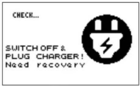
If a battery is very flat, a recovery cycle will start, lasting 2 minutes.
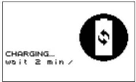
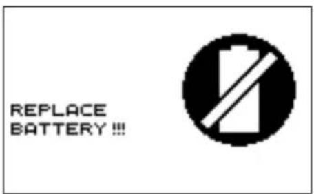
When this has finished, if the battery is working properly, it will start charging; in this case, it is strongly recommended to perform a charge/discharge cycle for the battery by pressing on the channel 4 button to launch this cycle, which may take up to 12 hours. If, however, it proves to be faulty, the following screen appears and the battery must be replaced.
5. DEVICE MAINTENANCE
GUARANTEE
See the attached leaflet.
MAINTENANCE
Your stimulator does not require neither calibration nor periodic maintenance. However when needed clean with a soft cloth and solvent-free alcohol-based detergent. Use as little liquid as possible to clean the device. Do not disassemble the stimulator or the charger as they contain high-voltage components which could cause electrocution. This must be carried out by Compex-approved technicians or repair services. If your stimulator contains parts that appear to be worn or faulty, please contact the closest Compex customer service centre.
CONDITIONS FOR STORAGE/TRANSPORT AND USE
| STORAGE AND TRANSPORT USE | ||
| TEMPERATURE -20°C to 45°C 0°C to 40°C | ||
| MAXIMUM RELATIVE HUMIDITY 75% 30% to 75% | ||
| ATMOSPHERIC PRESSURE from 700 hPa to 1060 hPa from 700 hPa to 1060 hPa | ||
Do not use in areas at risk of explosion.
DISPOSAL
Batteries must be disposed of in accordance with national regulatory requirements in force. Any product bearing the WEEE label (a crossed-out wheeled bin) must be separated from household waste and sent to special collection facilities for recycling and recovery.
6. TECHNICAL SPECIFICATIONS
GENERAL INFORMATION
94121x rechargeable Nickel-metal hydride (NiMH) battery (4.8 V / ≥ 1200 mA/h).
Battery chargers: only battery chargers with the part number 6830xx can be used to recharge the batteries supplied with the stimulator.
Product and accessories (excluded battery) expected service life: 5 years
Electrode shelf life: refer to electrodes bag
NEUROSTIMULATION
All the electrical specifications are supplied with an impedance from 500 to 1000 ohms per channel.
Channels: four independent and individually adjustable channels, electrically isolated from each other. Impulsion form: constant rectangular current with pulse compensation to eliminate any direct current component to prevent residual polarisation at skin level.
Maximum pulse intensity: 120 mA.
Pulse intensity increments: manual adjustment of stimulation intensity from 0 to 999 (energy) by minimum increments of 0.5 mA.
Pulse amplitude: from 60 to 400 μs.
Maximum electrical charge per pulse: 96 microcoulombs (2 x 48 μC, compensated).
Standard pulse ramp-up time: 3 μs (20 %-80 % of maximum current).
Pulse frequency: 1 to 150 Hz.
INFORMATION ABOUT ELECTROMAGNETIC COMPATIBILITY (EMC)
The stimulator is designed to be used in typical domestic environments approved in accordance with the safety standard EMC EN 60601-1-2.
This device emits very low levels in the radio frequency (RF) interval and is therefore not likely to cause interference with nearby electronic equipment (radios, computers, telephones, etc.).
The stimulator is designed to withstand foreseeable disturbances originating from electrostatic discharge, magnetic fields from the power supply or radio frequency emitters.
However, it is not possible to guarantee that the stimulator will not be affected by powerful RF (radio frequency) fields originating, for example, from mobile phones.
For more detailed information about electromagnetic emissions and immunity, please contact Compex.
STANDARDS
To ensure your safety, the stimulator has been designed, manufactured and distributed in accordance with the requirements of the amended European Directive 93/42/EEC covering medical devices.
The stimulator also complies with the IEC 60601-1 standard covering general safety requirements for electromedical devices, with the IEC 60601-1-2 standard covering electromagnetic compatibility and the IEC 60601-2-10 standard covering special safety requirements for nerve and muscle stimulators.
In accordance with current international standards in force, a warning must be given about applying electrodes to the thorax (increased risk of cardiac fibrillation).
The stimulator also complies with Directive 2012/19/EU covering waste electrical and electronic equipment (WEEE).
7. EMC TABLE
The Compex stimulator needs special precautions regarding EMC and needs to be installed and put into service according to the EMC information provided.
Portable and mobile RF communications equipment can affect the Compex stimulator.
The use of Accessories, transducers, and cables other than those specified by the manufacturer, may result in increased Emissions or decreased Immunity of the Compex stimulator.
The Compex stimulator should not be used adjacent to or stacked with other equipment and if adjacent or stacked use is necessary, the Compex stimulator should be observed to verify normal operation in the configuration in which it will be used.
| GUIDANCE AND MANUFACTURER'S DECLARATION – ELECTROMAGNETIC EMISSIONS | ||
| The Compex stimulator is intended for use in the electromagnetic environment specified below. The customer or the user of the Compex stimulator should assure that it is used in such an environment. | ||
| EMISSION TESTS COMPLIANCE | ELECTROMAGNETIC ENVIRONMENT – GUIDANCE | |
| Radiated Emissions CISPR 11 Group 1 | The Compex uses RF energy only for its internal function. Therefore, its RF emissions are very low and are not likely to cause any interference in nearby electronic equipment. | |
| Conducted Emissions CISPR 11 Class B | ||
| Harmonic emissions IEC 61000-3-2 Class A | The Compex is suitable for use in all establishments, including domestic establishments and those directly connected to the public low-voltage power supply network that supplies buildings used for domestic purposes. | |
| Voltage fluctuations IEC 61000-3-3 Complies | ||
| GUIDANCE AND MANUFACTURER'S DECLARATION - ELECTROMAGNETIC IMMUNITY | |||
| The Compex stimulator is intended for use in the electromagnetic environment specified below. The customer or the user of the Compex stimulator should assure that it is used in such an environment. | |||
| IMMUNITY TEST | IEC 60601TEST LEVEL | COMPLIANCE LEVEL | ELECTROMAGNETIC ENVIRONMENT -GUIDANCE |
| Electrostatic discharge(ESD) IEC 61000-4-2 | ±6kV contact±8kV air | ±6kV contact±8kV air | Floors should be wood, concrete or ceramictile. If floors are covered with synthetic material, the relative humidity should be at least 30%. |
| Electrical fast transient/burstIEC 61000-4-4 | ±2kV for power supply lines±1kV for input/output lines | ±2kV (power lines)Not Applicable(I/O lines) | Mains power quality should be that of a typical commercial or hospital environment. |
| SurgeIEC 61000-4-5 | ±1kV Line to Line (or Neutral)±2kV line(s) to earth | ±1kV Line to LineNot Applicable(Line to Earth) | Mains power quality should be that of a typical commercial or hospital environment. |
| Voltage dips, short interruptions and voltage variations on power supply input linesIEC 61000-4-11 a | <5% UT(>95% dip in UT) for 0,5 cycle40% UT(60% dip in UT) for 5 cycles70% UT(30% dip in UT) for 25 cycles<5% UT(>95% dip in UT) for 5 sec | <5% UT(>95% dip in UT) for 0,5 cycle40% UT(60% dip in UT) for 5 cycles70% UT(30% dip in UT) for 25 cycles<5% UT(>95% dip in UT) for 5 sec | Mains power quality should be that of a typical commercial or hospital environment.If the user of the Compex stimulator requires continued operation during power mains interruptions, it is recommended that the Compex stimulator be powered from an uninterrupted power supply or a battery. |
| Power frequency(50/60Hz) magnetic field IEC 61000-4-8 | 3 A/m 3 A/m | Power frequency magnetic fields should be at levels characteristic of a typical location in a typical commercial or hospital environment. | |
| a UT is the a.c mains voltage prior to application of the test level. | |||
| Conducted RFIEC 61000-4-6Radiated RFIEC 61000-4-3 | 3 Vrms150 kHz to 80 MHz3 V/m1.4 GHz to 2,7 GHz10 V/m26MHz to 1GHz | 3Vrms3V/m10V/m | Portable and mobile RF communications equipment should be used no closer to any part of the Compex stimulator, including cables, than the recommended separation distance calculated from the equation applicable to the frequency of the transmitter. Recommended separation distance d = 1.2 d = 1.2 80 MHz to 800 MHz d = 2.3 800 MHz to 2,5 GHzwhere P is the maximum output power rating of the transmitter in watts (W) according to the transmitter manufacturer and d is the recommended separation distance in metres (m).Field strengths from fixed RF transmitters, as determined by an electromagnetic site surveya, should be less than the compliance level in each frequency rangeb.Interference may occur in the vicinity of equipment marked with the following symbol: |
| NOTE 1 At 80 MHz and 800 MHz, the higher frequency range applies.NOTE 2 These guidelines may not apply in all situations. Electromagnetic propagation is affected by absorption and reflection from structures, objects and people. | |||
| ^a Field strengths from fixed transmitters, such as base stations for radio (cellular/cordless) telephones and land mobile radios, amateur radio, AM and FM radio broadcast and TV broadcast cannot be predicted theoretically with accuracy. To assess the electromagnetic environment due to fixed RF transmitters, an electromagnetic site survey should be considered. If the measured field strength in the location in which the Compex stimulator is used exceeds the applicable RF compliance level above, the Compex stimulator should be observed to verify normal operation. If abnormal performance is observed, additional measures may be necessary, such as reorienting or relocating the Compex stimulator. ^b Over the frequency range 150 kHz to 80 MHz, field strengths should be less than 3 V/m. | |||
| RECOMMENDED SEPARATION DISTANCES BETWEEN PORTABLE AND MOBILE RF COMMUNICATIONS EQUIPMENT AND THE COMPEX STIMULATOR | |||
| The Compex stimulator is intended for use in an electromagnetic environment in which radiated RF disturbances are controlled. The customer or the user of the Compex stimulator can help prevent electromagnetic interference by maintaining a minimum distance between portable and mobile RF communications equipment (transmitters) and the Compex stimulator as recommended below, according to the maximum output power of the communications equipment. | |||
| RATED MAXIMUM OUTPUT POWER OF TRANSMITTER W | SEPARATION DISTANCE ACCORDING TO FREQUENCY OF TRANSMITTER M | ||
| 150 KHZ TO 80 MHZ D = 1.2 √P | 80 MHZ TO 800 MHZ D = 1.2 √P | 800 MHZ TO 2,5 GHZ D = 2.3 √P | |
| 0,01 0,12 0,12 | 0,23 | ||
| 0,1 0,38 0,38 | 0,73 | ||
| 1 1,2 1,2 2,3 | |||
| 10 3,8 3,8 7,3 | |||
| 100 12 12 23 | |||
| For transmitters rated at a maximum output power not listed above, the recommended separation distance d in meters (m) can be estimated using the equation applicable to the frequency of the transmitter, where P is the maximum output power rating of the transmitter in watts (W) according to the transmitter manufacturer.NOTE 1 At 80 MHz and 800 MHz, the separation distance for the higher frequency range applies.NOTE 2 These guidelines may not apply in all situations. Electromagnetic propagation is affected by absorption and reflection from structures, objects and people. | |||
COMPEX®
Cross Training
MODE D'EMPLOI
TABLE DES MATIÈRES
natural_image
Line drawing of a rectangular device with labeled ports H and G (no text or symbols beyond labels)5. ENTRETIEN DE L'APPAREIL
GARANTIE
Consulter la notice jointe.
MAINTENANCE
natural_image
Line drawing of a rectangular device with labeled ports H and G (no text or symbols beyond labels)natural_image
Line drawing of a rectangular device with labeled ports H and G (no text or symbols beyond labels)ABCDE
PROGRESSIONE DEL PROGRAMMA
GUASTO AGLI ELETTRODI
5. MANUTENZIONE DEL DISPOSITIVO
GARANZIA
natural_image
Line drawing of a rectangular device with labeled ports H and G (no text or symbols beyond labels)BESCHRIJVING VAN HET APPARAAT


natural_image
Line drawing of a rectangular device with labeled ports H and G (no text or symbols beyond labels)4. PROBLEEMOPLOSSING
ELEKTRODESTORING
5. ONDERHOUD VAN HET APPARAAT
GARANTIE
Zie bijsluiter.
ONDERHOUD
natural_image
Line drawing of a rectangular device with labeled ports H and G (no text or symbols beyond labels)flowchart
graph LR
    A["Power plug"] --> B["COMPEX"]
natural_image
Close-up of a hand inserting a network switch into a USB port (no text or symbols visible)PROGRESSO DO PROGRAMA
INNEHÅLLSFÖRTECKNING
FÖRDELAR MED ELEKTROSTIMULERING
natural_image
Line drawing of a rectangular device with labeled ports H and G (no text or symbols beyond labels)

- EXPLANATION OF SYMBOLS
- HOW DOES ELECTROSTIMULATION WORK?
- STIMULATION OF MOTOR NERVES (EMS)
- STIMULATION OF SENSORY NERVES
- BENEFITS OF ELECTROSTIMULATION
- DEVICE FUNCTION
- DEVICE DESCRIPTION
- BATTERY INSERTION
- CONNECTIONS
- CHARGER CONNECTION
- CONNECTING THE CABLES
- PRELIMINARY SETTINGS
- CHOOSING A CATEGORY
- TOP 5
- SELECTING A PROGRAMME
- ADJUSTING STIMULATION INTENSITIES
- PROGRAMME PROGRESSION
- END OF A PROGRAMME
- BATTERY LEVEL AND CHARGING
- BATTERY LEVEL
- RECHARGING
- TROUBLESHOOTING
- ELECTRODE FAULT
- STIMULATION DOES NOT PRODUCE THE USUAL SENSATION
- STIMULATION CAUSES DISCOMFORT
- THE STIMULATOR IS NOT WORKING
- THE BATTERY IS VERY FLAT
- DEVICE MAINTENANCE
- GUARANTEE
- MAINTENANCE
- DISPOSAL
- TECHNICAL SPECIFICATIONS
- GENERAL INFORMATION
- NEUROSTIMULATION
- INFORMATION ABOUT ELECTROMAGNETIC COMPATIBILITY (EMC)
- STANDARDS
- EMC TABLE
- COMPEX®
- Cross Training
- TABLE DES MATIÈRES
- ENTRETIEN DE L'APPAREIL
- GARANTIE
- PROGRESSIONE DEL PROGRAMMA
- MANUTENZIONE DEL DISPOSITIVO
- GARANZIA
- BESCHRIJVING VAN HET APPARAAT
- PROBLEEMOPLOSSING
- ELEKTRODESTORING
- ONDERHOUD VAN HET APPARAAT
- ONDERHOUD
- PROGRESSO DO PROGRAMA
- INNEHÅLLSFÖRTECKNING
- FÖRDELAR MED ELEKTROSTIMULERING
Brand : COMPEX
Model : CrossTraining
Category : Fitness Equipment