S360EW - Boiler Whale - Free user manual and instructions
Find the device manual for free S360EW Whale in PDF.


| Product Type | 12V Water Heater for Boat |
| Brand | Whale |
| Model | S360EW |
| Capacity | 12 litres (3 US gallons) |
| Power Supply | 12 V DC, 300 W |
| Rated Current | 30 A |
| Recommended Fuse | 35 A |
| Maximum Water Temperature | 60 °C (140 °F) |
| Temperature and Pressure Relief Valve | 99 °C, 5.2 bar (75 psi) |
| Dimensions (L x W x H) | 343 mm x 369 mm x 337 mm (13.5 x 14.5 x 13.25 inches) |
| Weight | 5 kg (11 lb) |
| Tank Material | ALCLAD |
| Housing Material | White powder-coated aluminum |
| Connections | 1/2" female NPT (15 mm quick adapter WX1514 possible) |
| Usage Type | Pleasure marine, only with engine at cruising speed |
| Heating time (from 15 °C to 60 °C) | Approximately 80 minutes |
| Hot water retention | Up to 10 hours after shutdown |
| Safety | T&P valve, resettable temperature limiter, dry-run protection |
| Sacrificial anode | Magnesium (ref. SK3S360EW), check every 6 months |
| Maintenance | Exterior cleaning with damp cloth, descaling possible |
| Warranty | 2 years |
| Standards | ABYC E-11, ABYC H-23, directive 2001/95/CE, RoHS |
Frequently Asked Questions - S360EW Whale
User questions about S360EW Whale
0 question about this device. Answer the ones you know or ask your own.
Ask a new question about this device
Download the instructions for your Boiler in PDF format for free! Find your manual S360EW - Whale and take your electronic device back in hand. On this page are published all the documents necessary for the use of your device. S360EW by Whale.
USER MANUAL S360EW Whale
INSTALLATION AND OPERATION MANUAL
Whale® 12 V Water Heater
Model Number Description
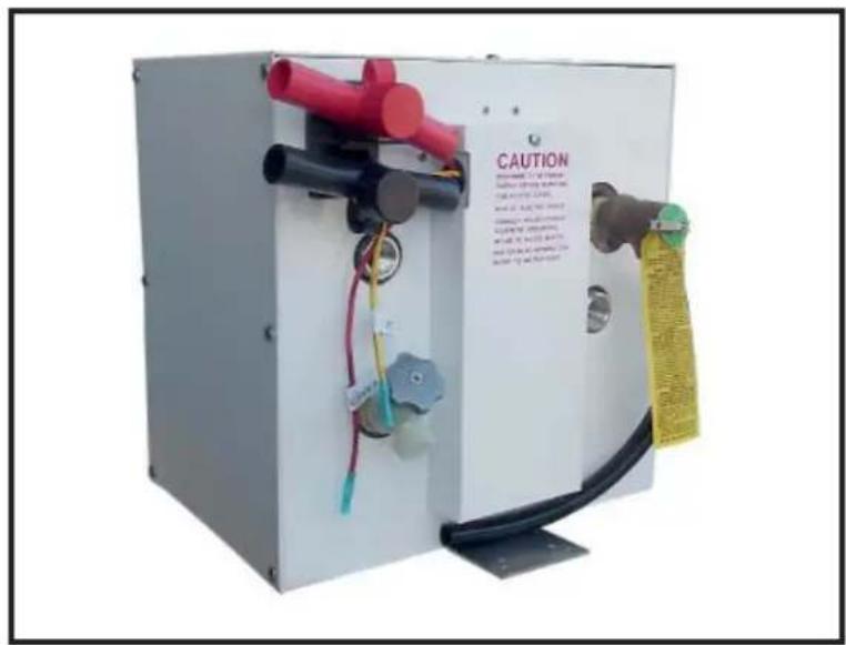
S360EW 12 V Electric Water Heater
SYSTEM REQUIREMENTS:
Minimum of a 100HP engine with at least a 30A residual current at cruising speed within a dual battery system
or
A dedicated 12 V battery source with 30A available
PLEASE NOTE: When connected to your boat 12 V system, care must be taken to ensure the heater is only operational at cruising speed. The heater must be switched off when the vessel is idling, this will prevent battery power drainage.
INSTALLATION AND USER INSTRUCTIONS
Thank you for purchasing this Whale® product. For over 30 years, Whale® has led the way in the design and manufacture of water systems including freshwater, bilge, gray and black waste management, faucets, showers, plumbing and accessories in the marine and RV industries. Whale® products are built on a reputation for quality, reliability and innovation backed up by excellent customer service.
For more information please visit www.whalepumps.com
- SPECIFICATION
| Product Code S360EW | |
| Description 12 V Electric Water Heater | |
| Capacity 3 US Gals (12 ltrs) | |
| Electrical Supply 12 V d.c. , 300W | |
| Recommended Fuse Size 35 Amps | |
| Current Draw 30 Amps | |
| Maximum Water Temperature 140 °F (60 °C) | |
| Temperature and Pressure Valve Specification | 210°F (99°C), 75 psi (5.2 bar) |
| Maximum Tested Pressure 300psi (20.7 bar)* | |
| Dimensions (wxdxh) 13 1⁄2" x 14 1⁄2" x 13 1⁄4" (3 | 43mm x 369mm x 337mm) |
| Materials | Tank - ALCLAD Casing - White Powder Coated Aluminium |
| Connections | 1⁄2" NPT FemaleFor connection to 15mm Quick Connect use WX1514 |
| Weight | 11lbs (5kg) |
*Note, ABYC Test requirements 125 psi, H-23
2. LIST OF CONTENTS AND LIST OF DIAGRAMS
- SPECIFICATION
- CONTENTS AND DIAGRAMS
- PRINCIPLES OF OPERATION
- TO THE USER
- TO THE FITTER
- APPLICATION
- WARNINGS
- INSTALLATION
- INSTRUCTIONS FOR USE
- MAINTENANCE
- WINTERIZING
- TROUBLE SHOOTING
- SERVICE SUPPORT DETAILS
- PATENTS/ TRADEMARKS
- WARRANTY STATEMENT
- EU DECLARATION OF CONFORMITY
LIST OF DIAGRAMS:
-
Mounting the Water Heater
-
Inlet and Outlet Ports
-
Grounding Instructions
-
Wiring Diagram
-
Typical Installation
-
Replacing the Anode
-
Internal Wiring
3. PRINCIPLES OF OPERATION
The Whale® 12 V Water Heater is designed for use on outboard boats to provide hot water on the go. It requires a 12 V d.c. power supply to heat water to 140F in less than 80 minutes and has integrated safety features including temperature and pressure valves, thermal cut-out and heating indication output.
4. TO THE USER
Read the following carefully before installation and use.
5. TO THE FITTER
WARNING: Please note that incorrect installation may invalidate the warranty. Check that the product is suitable for the intended application, follow these installation instructions and ensure all relevant personnel read the points listed below. Also ensure that these operating instructions are passed on to the end user.
6. APPLICATION
This Whale® 12 V Water Heater is designed for use in recreational marine vessels with a suitable power output operating on 12 V d.c. electrical supply only. If it is intended for any other purpose, it is the user's responsibility to ensure that the heater is suitable for the intended use. Whale® heaters are not suitable for domestic applications.
7. WARNINGS

Please note: When using electrical appliances, basic safety precautions must be followed to reduce the risk of fire, electrical shock, or injury.
This Whale® Heater must be installed by a qualified marine electrician.
CAUTION
Hydrogen Gas
- Hydrogen Gas can be produced in a hot water system that has not been used for a long period of time (generally 2 weeks or more). Hydrogen gas is extremely flammable.
- To reduce the risk of injury under these conditions, prior to using electrical appliances, the user must ensure that the hot water faucets in the galley are opened for several minutes until there is a smooth water flow. If hydrogen is present, there will be an unusual sound similar to air escaping through the pipe as the water begins to flow.
• Run the faucet for several minutes until there is a smooth water flow to release all the gas.
• WARNING - Do not smoke or have any open flame near the faucet when checking for hydrogen.
Galvanic Corrosion
- To help prevent possible damage due to electrolysis, installing a galvanic isolator is recommended.
• Galvanic corrosion is not covered under warranty.
Corrosion
- Corrosion may occur in your Water Heater due to high current or in areas of hard water with a higher concentration of dissolved salts.
• This Water Heater is therefore supplied with a sacrificial anode to prevent rapid corrosion. - Anode rods preserve the life of a Water Heater by corroding themselves instead of the heater.
• These anode rods are easy to replace and must be checked for corrosion every 6 months. Please see Maintenance (Section 10) for more information.
• Please note - Zinc anodes do not prevent corrosion, magnesium anodes are recommended.
Warnings - Please read prior to installation
- Read all instructions prior to installation and use.
- This Water Heater must be connected to a properly grounded source for aluminium boats (see Section 8 iv).
- WARNING This Water Heater is powered by 12 V d.c. and can draw up to 30 amps. Turn off power prior to installation or maintenance to prevent injury or death.
- Install and locate this Water Heater only in accordance with the provided installation instructions.
- This Whale® Water Heater is designed for use in a marine vessel only to provide hot water. If it is intended for any other purpose, it is the user's responsibility to ensure that the heater is suitable for the intended use.
- The water temperature cannot be adjusted. It is automatically set to approximately 140 F / 60 C to prevent bacteria growth.
- To avoid scalding, the temperature of the hot water supplied to faucets and showers must be controlled via a thermostatic mixer valve or similar as per ABYC H-23 standards (see section 8 vii.).
- Do not use water from the Water Heater as drinking water.
- Close adult supervision is necessary when this heater is being used by children or vulnerable adults.
- Do not operate this Water Heater if the power supply line is damaged, if the heater is not working properly, or if it has been damaged or dropped.
- Do not flush caustic chemicals through your system as this will cause damage to your heater. Damage that occurs to the heater due to caustic chemicals is not covered under warranty.
- WARNING: Fire hazard. Wiring must comply with applicable electrical standards and include a properly sized fuse or circuit breaker. Improper wiring can cause a fire resulting in injury or death. Switch off the power while making connections. Suggested wiring information is given as guidance only. For full information, refer to the USCG, ABYC and ISO regulations for marine applications and wiring gauges, connectors and fuse protection.
Contact Whale® Support team for further technical advice
USA: +1 616 897 9241 or email: usasales@whalepumps.com
ROW: +44 (0)28 9127 0531 or email info@whalepumps.com
8. INSTALLATION
NOTE: Incorrect installation will invalidate warranty and could make the Water Heater unsafe for use. Ensure your heater is properly installed and grounded by a qualified marine electrician.
8.i Preparation
• Always disconnect power sources before installing.
8.ii Location
- Locate the Water Heater as close to the power supply as possible.
- Locate the heater in a dry location away from the bilge area and standing water.
- Do not install the Water Heater on its side or upside down.
8.iii Mounting Instructions
- Mount this product on a fl at, horizontal surface only.
2 -
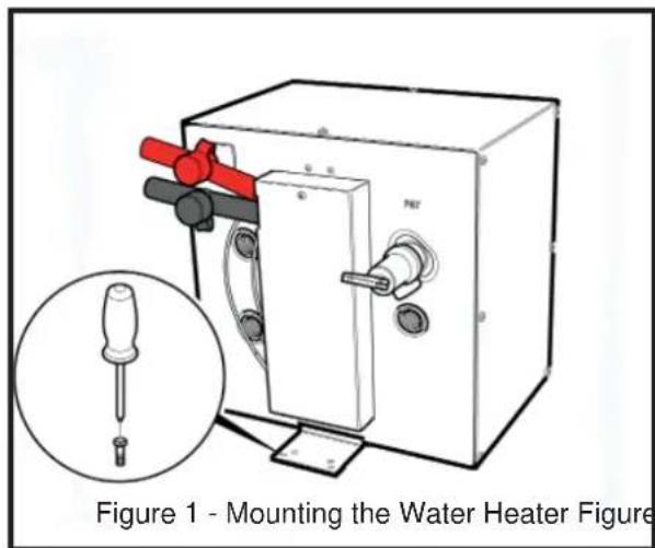
Step 1 Secure mounting brackets to structure with eight #12 minimum screws or 1/4 " (6.3mm) screws and nuts (See figure 1.). The minimum mounting surface depth is 1/2 " (12.5mm).
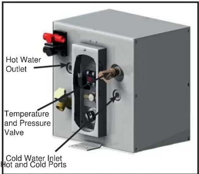
Step 2 Connect the cold water supply and hot water outlet to heater (see figure 2) using 1/2 " N.P.T. fittings on WX1514 / WX1524B for a Whale® Quick Connect system.
NOTE: Whale® recommends the use of a metal Braided Hose Connector on the hot outlet for connection to standard fl exible pipework.
Step 3 The Temperature and Pressure Relief Valve (provided with tubing) must be oriented so that discharge can exit no more than 6" (152.3mm) above, or at any distance below the structural floor. This must not be in contact with any live electrical part.
The Temperature and Pressure Relief Valve is factory installed. The pressure relief limits the pressure to 75 psi (5 bar) +/- 10% and the temperature to 210°F / 99°C +/- 10%. For replacement parts see Maintenance (Section 10) or contact Whale® Support.
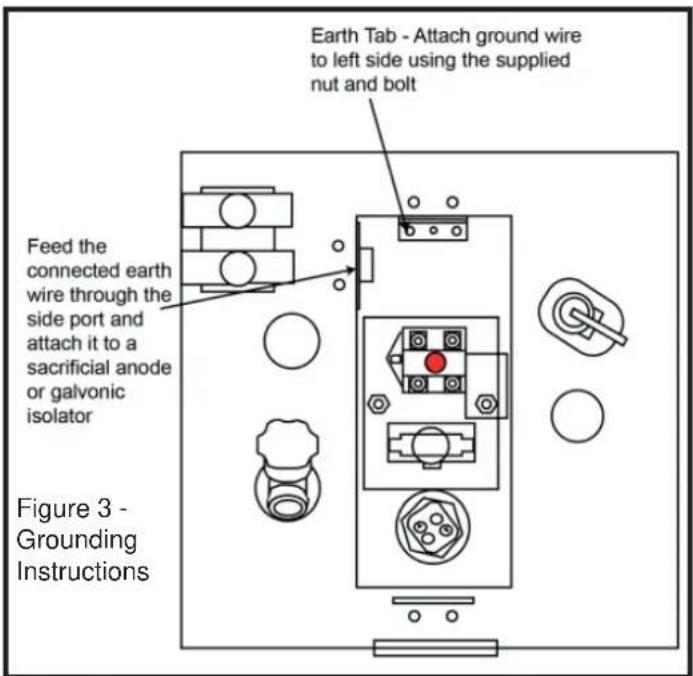
8.iv Grounding Instructions - Aluminium Boats
NOTE For aluminium boats the earth of the water heater must be connected to a separate sacrificial anode or galvonic isolator.
NOTE Do not connect the earth wire to the negative of the 12 V circuit.
Step 1 Remove the electrical access panel to gain access to the earth tab. This is located at the top of the internal panel and labelled with the earth symbol (see figure 3).
EARTH
SYMBO

Step 2 The separate ground / bonding strip must be connected to the water heater using the supplied green and yellow wire. The connection is made to the internal earth tab using the bolt and nut supplied.
NOTE: Do not place a switch in the grounding circuit.
8.v Electrical Wiring
- WARNING: Fire hazard. Wiring must comply with applicable electrical standards and include a properly sized circuit breaker. Improper wiring can cause a fire resulting in injury or death.
- Switch off the power prior to making connections.
- Suggested wiring information is given as a guide only. For full information, refer to USCG, ABYC and ISO regulations for marine applications and wiring gauges, connectors and circuit protection.
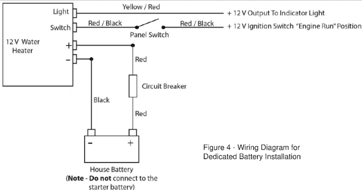
NOTE: Electrical wiring must comply with the wiring diagram (Figure 4). The switch must be connected to the 12 V ignition switch in the engine run position to ensure the heater is only operational when the engine is running.
Care must be taken to ensure the heater is only operational at cruising speed. The heater must be switched off when the vessel is idling, this will prevent battery power drainage.
NOTE: On 12 volt circuits a 35 amp circuit breaker must be used.
NOTE: For a dual battery system, Whale® recommends the use of a Battery Management System.
8.vi Fitting The Circuit Breaker
The purpose of this circuit breaker is to protect the appliance from serious damage, therefore please ensure a 35 Amp circuit breaker is installed between the water heater and auxiliary battery prior to use. This will protect the system from damage.
If the breaker blows:
a) Check for reverse polarity connection.
b) Check the breaker in the system is correct for the model.
c) Check there have been no power surges.
d) Check all electrical connections.
8.vii. Thermostatic Mixer Valve
NOTE: A Thermostatic Mixer Valve must be installed as a temperature control device to prevent risk of injury. This is as per ABYC H-23 standards.
- The Thermostatic Mixer Valve can be installed either on each outlet or as a central control in a hot water system. (See figure 5).
- Whale® recommends the use of the Whale® Thermostatic Mixer Valve - WX1599B.
![graph TD A["Twist Deck Shower"] --> B["Quick Connect Elbow"] B --> C["Quick Connect Equal Tee"] C --> D["Stem Shut off Valve"] D --> E["Thermostatic Mixer"] E --> F["Water Heater"] F --> G["Non-return Valve"] G --> H["Expansion Vessel"] H --> I["Stern Shut off Valve"] I --> J["Elegance Combo Mixer"]…](/content/2026/04/698306/images/99d1c810ad356acd39435d6b0d257bdc6f9720023a4e711269f8ab81fe48c5b3.jpg)
Figure 5 - Typical Hot Water System
9. INSTRUCTIONS FOR USE
Before using this Water Heater please read the instructions for use:
- Do not operate heater unless it is completely full of water. If heater has been operated without water and fails to work, follow the switch reset instructions in Section 9.ii.
- The 12 V d.c. Water Heater can only be operated when the engine(s) are running at cruising speed to ensure batteries remain fully charged. Alternatively the Water Heater can be connected to a dedicated 12 V battery.
- If the boat is connected to the dockside water system, ensure that the system is turned off at the dock when not attended. Also ensure that a pressure regulator is fitted to the vessel.
- Heat up times are dependant on your installation and other variable factors including initial temperature of the water, power available and ambient temperatures.
• The water temperature cannot be adjusted. It is automatically set to approximately 140° F / 60° C to prevent bacteria growth.
• To avoid scalding, the temperature of hot water supplied to faucets and showers must be controlled via a thermostatic mixer valve as per ABYC H-23 standards (See section 8.vii). - Do not use water from the Water Heater as drinking water.
9.i Instructions for Use
- Fill the water system and completely fill the Water Heater tank according to boat or pump manufacturer's instruction, purging all pipes and outlets. NOTE - Depending on the boat system size, it may take time to fill and deliver a smooth flow of water from hot and cold outlets.
NOTE This water heater is not designed to run dry. Running the heater dry will result in damage to the system.
-
Locate and switch 'ON' the remote electrical switch for your water heater, if a running light is installed this will illuminate.
-
Typical heat up times for this Water Heater are as follows:
| Heat Up Time | |
| 140°F / 60°C 80 minutes | |
| 104°F / 40°C 41 minutes |
- The running light will remain lit until the water has reached 140° F / 60° C, then cycle on and off as the temperature is maintained. Once switched off, the Water Heater will retain usable hot water for up to 10 hours.
NOTE If the running light cuts out within the first 30 minutes of operation, turn off the Water Heater and refer to Reset Instructions (Section 9.ii).
-
Switch the remote electrical switch 'OFF' prior to turning off engines and ensure it remains off when you restart the engine.
-
The Temperature and Pressure Valve may weep during initial operation - this is normal and the valve will seal itself with use.
9.ii Reset Instructions
If the Water Heater has accidentally been operated without water and fails to work, the Water Heater is equipped with a high limit switch which can be manually reset. If the limit switch activates, proceed as follows:
- Turn power off at main power panel and remote switch.
- Ensure that the Water Heater is filled with water by filling the fresh water tank and running a hot tap until a smooth flow is achieved.
- Remove wiring access cover and fi brous dielectric paper.
- Depress red button on high temperature limit switch.
- Replace cover and turn power on.
- If temperature limit switch re-activates, contact Whale® Support (section 13).
10. MAINTENANCE
This Whale® Water Heater is designed to only require minimal maintenance.
WARNING: Before servicing, turn off all power and drain the system.
NOTE: Do not repair or replace any part of the Water Heater unless specifically recommended in the installation manual. For technical support contact Whale® Support (section 13).
Annual Checks
- Whale® advise an annual boat electrical system check that must be completed by an marine electrician.
Optimal Performance
- Ensure this product is regularly cleaned to ensure consistent performance.
• To clean and sterilise the inside of the Water Heater, use diluted sterilising fluid and fully rinse through with clean fresh water afterwards. - The outside of the appliance should not require cleaning. If it does, turn off all electrical supply at breaker and wipe down with a damp cloth only. Allow the Heater to fully dry prior to reconnecting the electrical supply.
NOTE Do not use abrasive cleaners on any Whale® Water Heater
• If de-scaling is required, this can be done using a de-scaling solution. Fully flush out the Water Heater after de-scaling.
Replacing the Anode
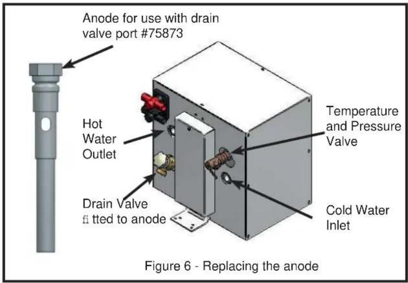
The Whale® replacement anode is Part # SK3S360EW.
- Drain tank fully and turn off power.
• To replace the anode, remove the drain valve and the pre-installed sacrificial anode (figure 6) and screw the new anode and drain valve back in its place.
- Whale® recommends checking the anode regularly for signs of corrosion. If you have any concerns about rapid corrosion, please contact Whale® Support (Section 13).
The following service items are available for this Water Heater from Whale® (Figure 7).
Heating Element #SK3S360EW Relay #75878
High Heat Limit Switch #74607 Temperature and Pressure Valve #74659
Magnesium Anode #75873 Thermostat #73129
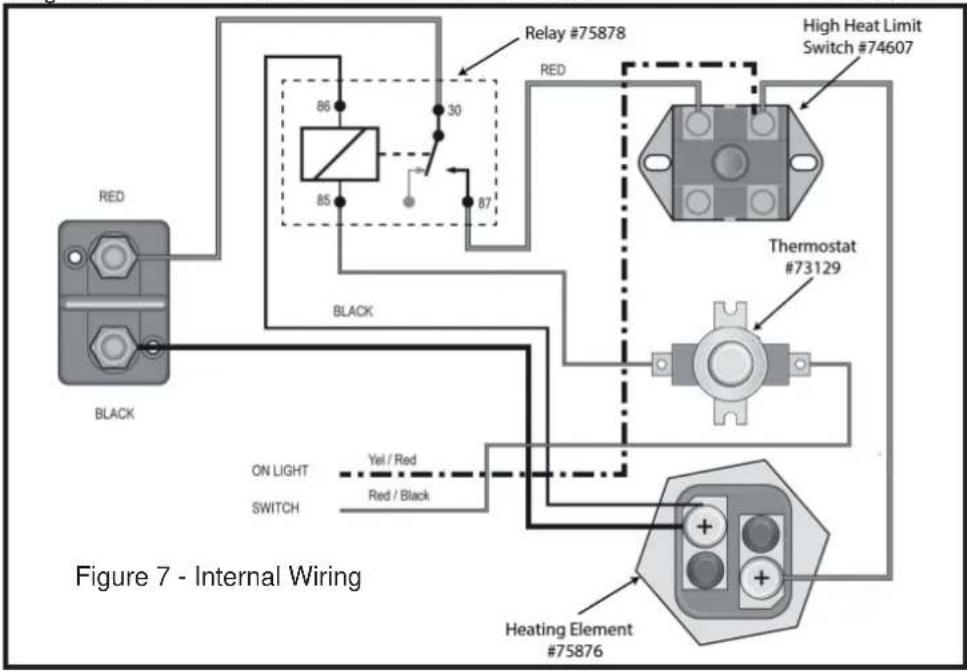
NOTE: Figure 7 depicts the internal wiring of this Water Heater. For advice on servicing any of the highlighted components please contact Whale® Support (Section 13) or a marine electrician.
11. WINTERIZING
Note - If water is allowed to freeze in the system, serious damage to the pipe work and pump may occur. Failures of this type will invalidate warranty. To best avoid this damage, completely drain the water system.
WARNING - The power source must be turned off before draining and refilling this Water Heater.
- Drain the complete freshwater system either using the pump or a drain valve.
- Open all the faucets (including the Water Heater drain valve) and allow pump to purge the water from the system, and then turn the pump off.
- Disconnect the pump and turn on to purge into an adequate basin. Only reconnect the pump when water system is to be used.
- Remember to leave all faucets including the Water Heater drain valve open to avoid any damage (except for Whale Twist™ Deck Shower if installed).
12. TROUBLESHOOTING
PROBLEM POSSIBLE CAUSES POTENTIAL SOLUTION
| No hot water | Cold water inlet valve is incorrectly orientated (if present) | Ensure check valve is the correct orientation (if present). |
| No water in the tank | Fill the tank with water. | |
| High Limit Switch activated | Press reset and try again. If this has no effect, contact a local electrician to replace the switch or element. | |
| Faulty element Replace element. | ||
| Incorrect wiring Check wiring and contact a marine electrician. | ||
| No / insufficient electricity supply | Contact a marine electrician to check the electrical supply. | |
| Faulty thermostat Replace the thermostat (Section 13). | ||
| Heavy calcification | Flush your hot water heater. If this has no affect, replace the heating element (section 10). | |
| Blocked ports or non return valve clear the blockage. | ||
| Thermomixer valve set too cold adjust to between 40°C ( 104°F ) and 55°C ( 131°F ). | ||
| Circuit breaker has blown Check and replace if necessary. | ||
| No power as water heater is activated while engine is not running | Recharge batteries and only use the water heater while the engine is activated. | |
| Circuit breaker tripped due to low power or insufficient water supply | Fill the water tank fully and only use while engine is running. | |
| No output from tank | Air lock Bleed the system. | |
| High limit Switch continually trips | Insufficient water in the tank | Check non-return valve is not blocked and fill tank to capacity. |
| Wrong breaker amperage | Check fuse rating to ensure correct amperage and replace if necessary. | |
| Faulty element Replace element. | ||
| Heavy calcification in water tank flush and clean regularly. | ||
| Faulty wiring Have a marine electrician check the electric circuit. | ||
| Pressure relief Valve (TMP/TMV) Leaking | Initial use | The T&P valve may leak on initial use until it seals itself. Open the valve and re-run the system. |
| Faulty / old valve Replace the valve. | ||
| Water Heater left constantly on | Replace valve (due to deposit build-up on valve seat) and do not leave Water Heater constantly ‘on’. | |
| Tank not winterized | Replace valve and winterize tank in future. | |
| Electric thermostatic controls faulty | Have a marine electrician check the system. | |
| Leaking tank | Damage to tank due to improper service | Replace Water Heater. |
| Electrolysis due to absent or faulty galvonic isolator | Replace Water Heater and install galvanic isolator. | |
| No anode fitted to tank | Replace Water Heater and fit anode in drain valve fitting | |
| Corrosion or damage due to tank not winterized properly | Replace Water Heater and ensure it is winterized in future. | |
| Fittings not correctly attached | Check all connections are water-tight. | |
13. SERVICE SUPPORT DETAILS
For installation or service advice please contact Whale® Customer Support:
UK Tel: +44 (0)28 9127 0531
USA Tel: +1 616 897 9241
UK Email: info@whalepumps.com
Email USA: usasales@whalepumps.com
14. PATENTS AND TRADEMARKS
Whale® is a registered trademark of Munster Simms Engineering limited.
15. WARRANTY STATEMENT
This Whale® product is covered by 2 years warranty. For further details please see the enclosed Statement of Limited Warranty. This product is manufactured by Attwood Corporation in the USA.
©Copyright Whale® 2017 - All rights reserved.
WHALE®, is a registered trademark of Munster Simms Engineering Limited, Bangor, Northern Ireland trading as Whale. Whale's policy is one of continuous improvement and we reserve the right to change specifications without prior notice. Illustrations are for guidance purposes only.
16. EU DECLARATION OF CONFORMITY, STANDARDS AND APPROVALS
We hereby declare, under our sole responsibility, that the enclosed equipment is in conformity with the following relevant EU legislation:
General Product Safety Directive 2001/95/EC
RoHS 2011/65/EU
Basis on which conformity is declared
The above equipment complies with the protection requirements of the stated directive.
Standards applied
ABYC E-11 AC and DC Electrical Systems on Boats (2003)
ABYC H-23 Installations of Potable Water Systems
Signature:

Name: Richard Bovill
Function: Engineering Director
Location: 2 Enterprise Road, Bangor, Northern Ireland, BT19 7TA
Date of Issue: 23rd October 2014
MANUEL D'INSTALLATION ET D'UTILISATION Chauffe-eau Whale 12V
FR
EXIGENCES DU SYSTÈME :
Lieu : 2 Enterprise Road, Bangor, Northern Ireland, BT19 7TA
ABYC E-11 AC and DC Electrical Systems on Boats (2003)
ABYC H-23 Installations of Potable Water Systems
Unterschrift:

Name: Richard Bovill
Ort: 2 Enterprise Road, Bangor, Northern Ireland, BT19 7TA
Sede: 2 Enterprise Road, Bangor, Northern Ireland, BT19 7TA
Lugar: 2 Enterprise Road, Bangor, Northern Ireland, BT19 7TA
Ort: 2 Enterprise Road, Bangor, Northern Ireland, BT19 7TA
8.v Sähköjohdot
ABYC H-23 Installations of Potable Water Systems / ###
Allekirjoitus:
Nimi: Richard Bovill
Osoite: 2 Enterprise Road, Bangor, Northern Ireland, BT19 7TA
©Copyright Whale 2017 - All rights reserved. Reproduction in whole or in part without permission is prohibited. WHALE® is a registered trademark of Munster Simms Engineering Limited, Bangor, Northern Ireland trading as Whale. Whale's policy is one of continuous improvement and we reserve the right to change specifications without prior notice. Illustrations are for guidance purposes only.
Neither the accuracy nor completeness of the information contained in any Product brochure is guaranteed by the Company and may be subject to change at its sole discretion.
Please note that by contacting Whale Support you will be indicating your consent to receiving product updates, recall information, help guides and appropriate marketing messages from us via post, email or telephone unless you indicated an objection to receiving such messages.
184.40_v5_1222_SO
Ref: 75874
- INSTALLATION AND OPERATION MANUAL
- MODEL NUMBER DESCRIPTION
- SYSTEM REQUIREMENTS
- INSTALLATION AND USER INSTRUCTIONS
- LIST OF CONTENTS AND LIST OF DIAGRAMS
- LIST OF DIAGRAMS
- PRINCIPLES OF OPERATION
- TO THE USER
- TO THE FITTER
- APPLICATION
- WARNINGS
- CAUTION
- HYDROGEN GAS
- GALVANIC CORROSION
- CORROSION
- WARNINGS - PLEASE READ PRIOR TO INSTALLATION
- INSTALLATION
- 8.I PREPARATION
- 8.II LOCATION
- 8.III MOUNTING INSTRUCTIONS
- 8.IV GROUNDING INSTRUCTIONS - ALUMINIUM BOATS
- 8.V ELECTRICAL WIRING
- 8.VI FITTING THE CIRCUIT BREAKER
- 8.VII. THERMOSTATIC MIXER VALVE
- INSTRUCTIONS FOR USE
- 9.I INSTRUCTIONS FOR USE
- 9.II RESET INSTRUCTIONS
- MAINTENANCE
- ANNUAL CHECKS
- OPTIMAL PERFORMANCE
- REPLACING THE ANODE
- WINTERIZING
- TROUBLESHOOTING
- SERVICE SUPPORT DETAILS
- PATENTS AND TRADEMARKS
- WARRANTY STATEMENT
- EU DECLARATION OF CONFORMITY, STANDARDS AND APPROVALS
- BASIS ON WHICH CONFORMITY IS DECLARED
- STANDARDS APPLIED
- MANUEL D'INSTALLATION ET D'UTILISATION CHAUFFE-EAU WHALE 12V
- EXIGENCES DU SYSTÈME
- 8.V SÄHKÖJOHDOT
Brand : Whale
Model : S360EW
Category : Boiler