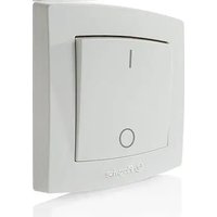
Switch - Electrical switch Plugwise - Free user manual and instructions
Find the device manual for free Switch Plugwise in PDF.


User questions about Switch Plugwise
0 question about this device. Answer the ones you know or ask your own.
Ask a new question about this device
Download the instructions for your Electrical switch in PDF format for free! Find your manual Switch - Plugwise and take your electronic device back in hand. On this page are published all the documents necessary for the use of your device. Switch by Plugwise.
USER MANUAL Switch Plugwise
natural_image
White Plugwise electrical switch with a circular button and indicator lights, emitting blue light trails (no text or symbols on the switch itself)Nederlands
natural_image
Close-up of a mechanical or electrical component with black and red components, no visible text or symbolsAchterplaat
natural_image
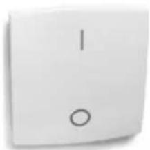
Close-up of a white electrical switch with two terminals (labeled '1' and '0') and no additional text or symbols.Knop
natural_image
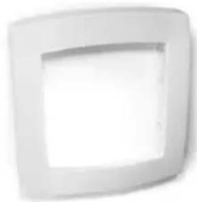
White square frame with a recessed recess, no text or symbols visibleSluitrand
text_image
Plugwise Switch kstrips2 AAA-batterijen
2 Wandpluggen
text_image
Diagram illustrating the working principle of an electrical switch, showing battery, motor, and power connections.Thank you for buying this extension to your Plugwise system. The Switch allows you to turn on and off the power to the appliance in your Plugwise network wirelessly. You can determine how many appliances you want to operate: for instance you can turn off the lighting of an entire floor by simply using the Switch. This does not require the computer to be on.
This manual describes the installation of a single Switch, but the same steps can be followed if you want to install multiple Switches at the same time.
Before you start
• We recommend that you follow this manual carefully; it is essential to take the steps in the correct order.
- To be able to use the Switch, you require a PI consisting of a Stick, Circle+ and a number of Circles.
A Plugwise network can never contain more Switches than 5 times the number of Circles. What this manual explains for the Circle also applies to the Stealth and the Sting, or a combination thereof.
- Ensure that you use the latest version of Source modules have the latest firmware version. You can check this by clicking the Updates button in Source. In Source, check whether the Stick and all of the modules are online.
- In Source, check whether the tick at the bottom left of the screen shows that the Stick is online:
- In Source, check in the tree at ‘Overviews’ whether all appliances are online. This is indicated by grey and yellow lights:
- Only insert the batteries when you start to use the Switch. A Switch uses a lot more power if it is not connected to a Plugwise network.
- To use the Switch, it must be connected to a Plugwise In Source you can select using 'Groups' the appliances that must be switched using the Switch. The Switch can then be attached to the wall. These steps are explained in more detail below.
- Check whether all components are present. If a cc missing, please contact us as soon as possible.
Content of the package
- For each Switch:
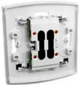
natural_image
Close-up of a mechanical or electrical component with two black rectangular blocks and red dots, no visible text or symbols.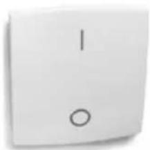
natural_image
Close-up of a white electrical switch with two terminals (labeled '1' and '0') and no additional text or symbols.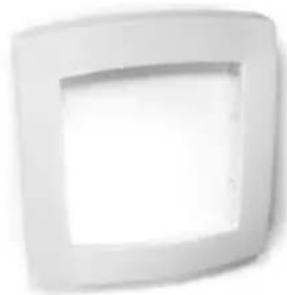
natural_image
White square frame with a recessed recess, no text or symbols visibleBackplate Surround Rocker
Dependent on the version of the Switch, single and/or double rockers are supplied.

- This Manual
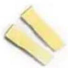
2 Screws2 Adhesive strips
text_image
Plugwise Switch ve strips2 AAA batteries
2 Wall plugs
1. Adding the Switch to your Plugwise network
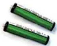
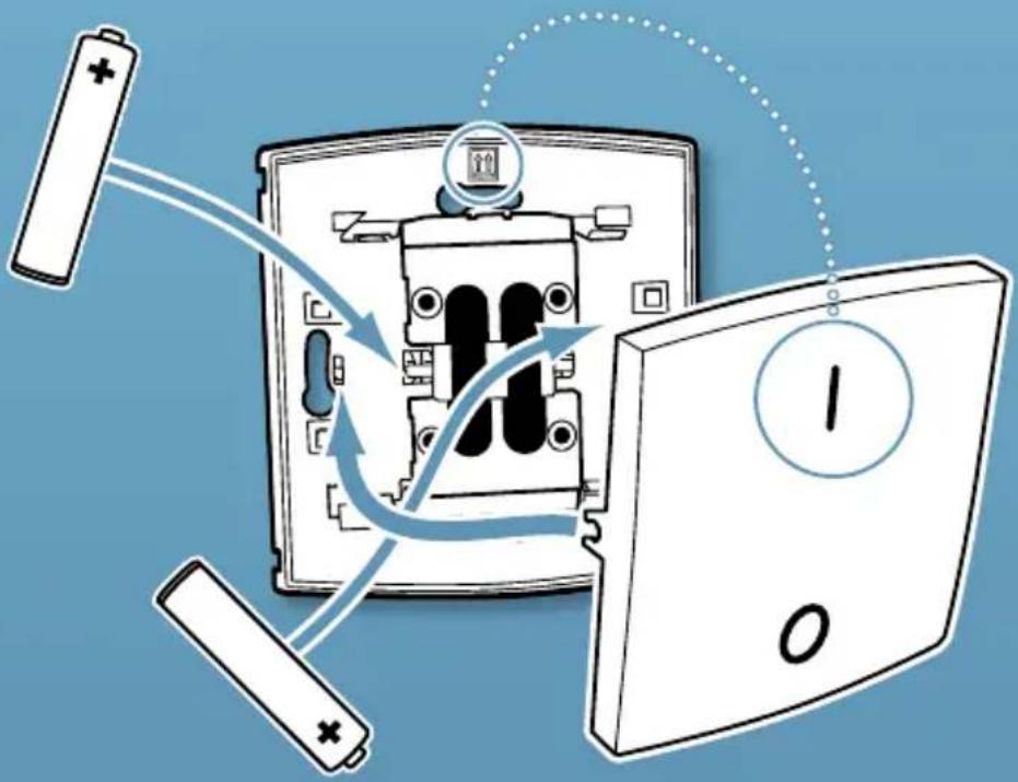
- Install the two AAA batteries in the Switch. Note the + and - marks. Only install the batteries if you are about to connect the Switch to the Plugwise network. As long as the Switch is not connected to a network, it will consume more power.
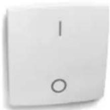
The two arrows on the inside of the back plate indicate the top. Ensure that the | mark of the rocker will be at the top. Click the rocker(s) onto the back plate:
text_image
Diagram illustrating battery charging process with labeled components and directional arrowsNote: do not install the surround yet!
Start Source and select Settings, Add Modules.
When you are asked to select a network, select the network to which the Switch must be added.
Fill in the ID of the Switch. This is shown on the stickers that are attached to the back.
- Click the button with the green arrow: If you want to install multiple Switches, add the IDs for all of the Switches to the list. The Plugwise network will then search for the Switches with the new IDs in the list.
Briefly press one of the rockers of the Switch every approximately 10 seconds, until Source shows that it is online. The circle with the question mark will then change into the following pictogram:
If the Switch is not found within several minutes, check whether the
Plugwise network is operating correctly (refer to 'Before you start'). If the Stick and the other modules are available in Source and the Switch is still not shown as being online, follow the instructions to delete the network settings under 'Delete network settings', see: 'Advanced use'.
Click 'Next' and then 'Finish'.
The Switch is now connected to your network.
2. Choosing the appliances to switch
The Switch can be assigned to a single appliance or appliances. This is done via 'Groups' in the Source settings you have the version with a double rocker, you can assign each side to different groups.
In Source go to Settings, Groups.
Click the + ('Create Group') button.
- Enter a recognisable name for the group, for instance 'Switch for ground floor'.
Press the Switch rocker once (if you have the double rocker version, press both rockers). The rocker switches are added to the list of rocker switches to assign in the lower half of the screen.
- Drag the rocker switch to the desired group. If you are using the single rocker version, select the module with 'Left' at the end of the name.
- Use the mouse to drag the appliances to be switched from the 'Appliances' list to the newly created group.
- Important: click 'Send Groups' to send the settings to your Plugwise network.
- Check whether the appliances in the group respond when the rockers of the Switch are pressed.
Take one of the labels that are on the back of the Switch and attach it to the installation list of your Plugwise network. Indicate on the list t group that is assigned to the Switch and where the Switch will be hung
A Switch can only be assigned to a single group. However, it is possible to assign a appliance to multiple groups.
3. Attaching the Switch to the wall
The Switch can be attached to the wall in two ways: using the adhesive strips or using screws.
Take the Switch to the location where it must be located. This must be within 5 to 10 metres of a Circle.
- Check whether the appliances that are assigned to the Switch respond to being switched on and off. It can take several minutes for t
network to process the new location of the Switch.
- Attach the Switch to the wall using the double-sided adhesive strips or the supplied screws.
If you decide to use screws in a hard wall, you should drill 5-mm holes and insert plugs.
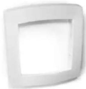
Once the position of the Switch has been finally determined, the surround can be fitted.
The surround can only be removed by inserting a screwdriver in the openings at the rear between the back plate and the surround. This ensures that the Switch cannot be removed or open environment, you can decide not to tighten the screws too tightly, so that the Switch can still be unscrewed.
4. Use
Switching appliances
The appliances that you have connected to the Switch using Source, will be switched off when you press the lower part of the rocker marked with the O and switched on when you push the part marked with the
The Switch contacts one of the Circles in your network forwards switching commands to the other Circles. If a Circle is part of the Switch's group, it performs the switching command. If the Circle that the Switch tries to contact is unavailable, a connection will be made with another Circle. This can take several seconds.
The computer does not need to be switched on to be able to use the Switch.
If the lighting is operated using the Switch, the recommendation is to no longer use the existing switches. You could consider letting an electrician remove the existing switches and install a Switch at the location that becomes available.
Assigning other appliances to the Switch
Source can be used to assign the appliances that must be operated with the Switch.
▶ Go to Settings, Groups.
On the left, search for the group in which the Switch is located.
- Drag other appliances to this group or drag the current appliances back to the top right-hand part of the screen.
Removing a Switch
- If the Switch will (temporarily) no longer be used, it can be removed from the Plugwise network.
- Start Source and go to Settings, Appliances.
The list of 'Non assigned modules' is displayed to the right of the screen. Right click the Switch and then click 'Delete'.
The Switch will now be ignored by the network.
It is impossible to remove a Switch that is screwed to the wall without damaging the surround.
5. Advanced use
Connecting a Switch to another network
After a Switch has been removed from a network (see the explanation above), it can be connected to another Plugwise system. To do this, follow the normal installation procedure.
Deleting network settings
If you try to add the Switch to a Plugwise network and it does not come online, you can delete the network settings from the Switch. The Switch contains a LED indicator light. If the Switch is assigned to a network, the light flashes if one of the rockers is pressed (the light is only visible in low-light conditions). Follow the steps below to delete the network settings.
- Press the top of the rocker marked | for three seconds. If the Switch has two rockers, use the left rocker for this procedure.
- Press the bottom of the rocker (marked 0) for three seconds.
- Press the top of the rocker for ten seconds.
- If after pressing one of the rockers the indicator light remains on for longer (several seconds), the network settings have been successfully deleted. If this is not the case, repeat the procedure. A watch with a second hand can be useful here.
Note: remove the batteries. As long as the Switch is not assigned to a network, it will consume more power.
Switching appliances in multiple networks at the same time
Users with a Source Pro licence can operate more than one network (multiple Sticks) simultaneously from Source. It is possible to create a group consisting of one Switch and appliances from various networks. The appliances will then be switched on and off using the Switch, but only if Source is running.
6. Environment
- Old electrical and electronic appliances often contain valuable materials. Therefore, never dispose of discarded appliances as normal household rubbish. Hand the appliance in to a local authority collection point for electrical and electronic appliances.
- Never throw batteries away with the household rubbish, but hand them in at the intended collection points.
7. Technical details
The meaning of the flashing LED
The LED light behind the rockers shines through the plastic, but is only visible in low-light conditions.
The LED flashes: a switching command is being sent. The LED remains flashing until the Circles have sent an acknowledgement command. This must occur within a second. If this is not the case, the Switch has just been installed and it is searching for another Circle to connect to. This also happens if the Circle is inaccessible.
The LED remains on for more than a second: the Switch is not assigned to a network and is searching for a network to connect to. In this mode, the Switch uses more power than normal.
Specifications
| Parameters Min. Nominal Max. Unit Remarks | |||||
| Power supply | |||||
| Supply voltage | 2,4 | 3,3 | Vdc | ||
| Power consumption | 150 | mW | |||
| Dimensions | 86 x 80 x 14 | mm | Height x width x depth | ||
8. Support and contact
A detailed Plugwise Source manual is displayed if you click the 'Help' button at the bottom of the screen. Our website contains a page of frequently asked questions:
www.plugwise.com
If you still have questions, please contact us via the contact form or via our service number as shown on the support page of our website. You can of course also contact us if components are missing. We would also be pleased to hear from you if you are happy with the delivered product.
Deutsch
natural_image
Close-up of a mechanical or electronic component with two black rectangular blocks and red dots, no visible text or symbols.Rückwand
natural_image
Close-up of a white square button with two circular symbols: one vertical and one centered, no text or numbers visible.Wippen
natural_image
White square frame with a recessed cutout, no text or symbols presentRahmen
text_image
Plugwise Switchtext_image
Diagram illustrating battery charging mechanism with labeled components and directional arrowsnatural_image
Close-up of a mechanical or electrical component with two black rectangular blocks and red dots, no visible text or symbols.Panneau arrière
natural_image
Close-up of a white electrical switch with two terminals (labeled '1' and '0') and a circle on the terminal (no additional text or symbols)Interrupteur
natural_image
White square-framed recessed panel or cover with a recessed top (no text or symbols)Bordure
text_image
Diagram illustrating battery charging process with labeled components and directional arrows indicating charging directionConnecting a Switch to another network
After a Switch has been removed from a network (see the explanation above), it can be connected to another Plugwise system. To do this, follow the normal installation procedure.
natural_image
Abstract wavy surface with grid lines, no text or symbols present