
303208 - Meter Aplic - Free user manual and instructions
Find the device manual for free 303208 Aplic in PDF.


| Product Type | Wireless Bike Computer |
| Brand | Aplic |
| Model | 303208 |
| Power Supply | 2 CR2032 3V batteries (one for main unit, one for sensor) |
| Dimensions (L x W x H) | 54 mm x 43 mm x 20.5 mm |
| Protection Rating | IP44 (protected against water jets) |
| Ambient Temperature | 0°C to +50°C |
| Sensor Type | Wireless Reed Sensor |
| Display | LCD with backlight (5 seconds) |
| Menu Languages | GB, DE, FR, NL, IT, ES |
| Main Functions | Time, stopwatch, temperature, speed, distance, duration, calories, fat, CO2, odometer, timer, scan mode |
| Max. Sensor-Magnet Distance | Less than 5 mm for optimal transmission |
| Auto Sleep | After about 4 minutes without signal |
| Reset | By button or removing battery |
| Memory | Yes (total distance, total time) |
| Box Contents | Computer, bracket, Reed sensor, magnet, cable ties |
| Mounting | On handlebar and fork |
| Cleaning | With a soft, dry cloth, no alcohol or harsh chemicals |
| Use in Rain | Possible but do not immerse |
Frequently Asked Questions - 303208 Aplic
User questions about 303208 Aplic
0 question about this device. Answer the ones you know or ask your own.
Ask a new question about this device
Download the instructions for your Meter in PDF format for free! Find your manual 303208 - Aplic and take your electronic device back in hand. On this page are published all the documents necessary for the use of your device. 303208 by Aplic.
USER MANUAL 303208 Aplic
natural_image
Blue and gray abstract logo design with no text or symbolsTable of contents
- Deutsch ....3
- English....18
- Français ....33
- Italiano ....48
- Español....63
ENG: Latest information, drivers, user manuals and data sheets can be found at www.ganzeinfach.de in our download area.
natural_image
Diagram of a bicycle wheel assembly with a sensor and wheel (no text or labels)Batterie einlegen
natural_image
Mechanical assembly diagram showing two views of a device with a labeled component 'B' (no text or symbols present)Installation des Magnets
natural_image
Diagram showing two mechanical components labeled A, one with a pin and arrow indicating direction (no text or symbols present)Radumfangsdiagramm
| Reifendurchschnitt | Radumfangswert (in mm) |
| 26 Zoll 57-559 2100 | |
| 26 Zoll 37-590 2090 | |
| 26 Zoll 60-559 2150 | |
| 27 Zoll 32-630 2180 | |
| 28 Zoll 20-622 2110 | |
| 28 Zoll 25-622 2130 | |
| 28 Zoll 30-622 2260 | |
| 28 Zoll 35-622 2185 | |
| 28 Zoll 37-622 2190 | |
| 28 Zoll 40-622 2220 | |
| 28 Zoll 42-622 2230 | |
| 28 Zoll 47-622 2280 | |
| 28 Zoll 50-622 2280 | |
| 28 Zoll 54-622 2295 | |
| 28 Zoll 60-622 2350 | |
| 28 Zoll 40-635 2240 | |
| Reifendurchschnitt Radumfangswert (in mm) | |
| 20 Zoll 40-406 1530 | |
| 20 Zoll 54-406 1590 | |
| 24 Zoll 47-507 1860 | |
| 24 Zoll 54-507 1920 | |
| 26 Zoll 25-559 1940 | |
| 26 Zoll 40-559 2000 | |
| 26 Zoll 50-559 2040 | |
6. Funktionen
Thank you for choosing an aplic product. Please read the following user manual carefully to have an enjoyable experience with your purchased product.
1. Scope of delivery
- Bicycle computer
- Bracket
- Reed-sensor (wireless)
- Spoke magnet
- Mounting accessories
2. Technical data
| Power supply Two 3V CR2032 batteries | |
| Dimensions (H x W x D) 54mm x 43mm x 20.5mm | |
| Degree of protection IP 44 (splash-proof protection) | |
| Operating temperature -0°C to +50°C | |
| Features • Time | • Stop watch• Temperature• Auto ON/OFF• Backlight• Speed display• Ride time display• Ride distance display• Built-in memory• Menu languages GB, DE, FR, NL, IT, ES |
3. Product details
UP bu on (+)
Down bu on (-)
Ba ery status
Speed
trend
Speed
Time
SET (S) bu on
MODE (M) bu on
4. Installation and Assembly
Remove the bicycle computer from the packaging and remove all the packaging material. Before start-up, ensure that the device does not have any external damage.
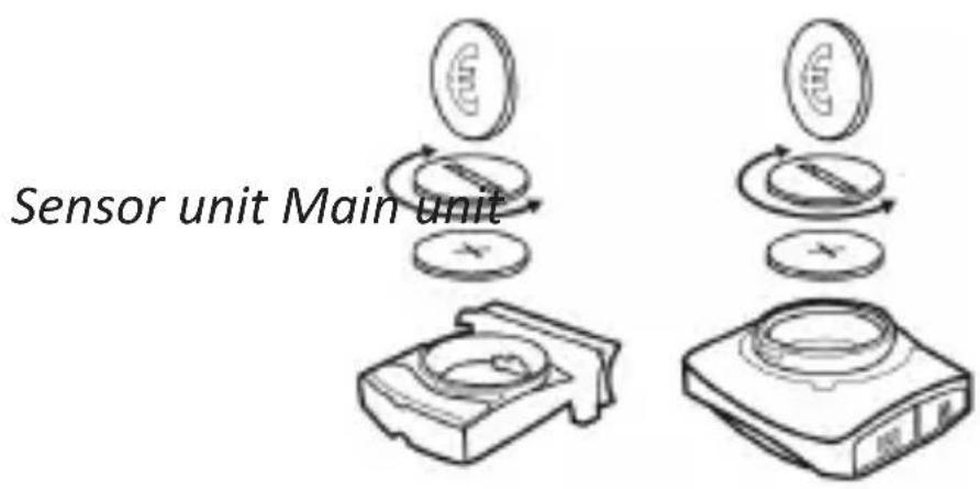
Insert the battery
Before commencing set-up, insert the battery into the battery compartment. To do this, open the battery compartment on the back of the main unit and the wireless sensor unit (Reed sensor) using a coin or a similar object by rotating it counter clockwise.
Insert a CR2032 3V battery into the battery compartment. Ensure that the positive pole of the battery is pointing towards the battery compartment cover. Then close the battery compartment.
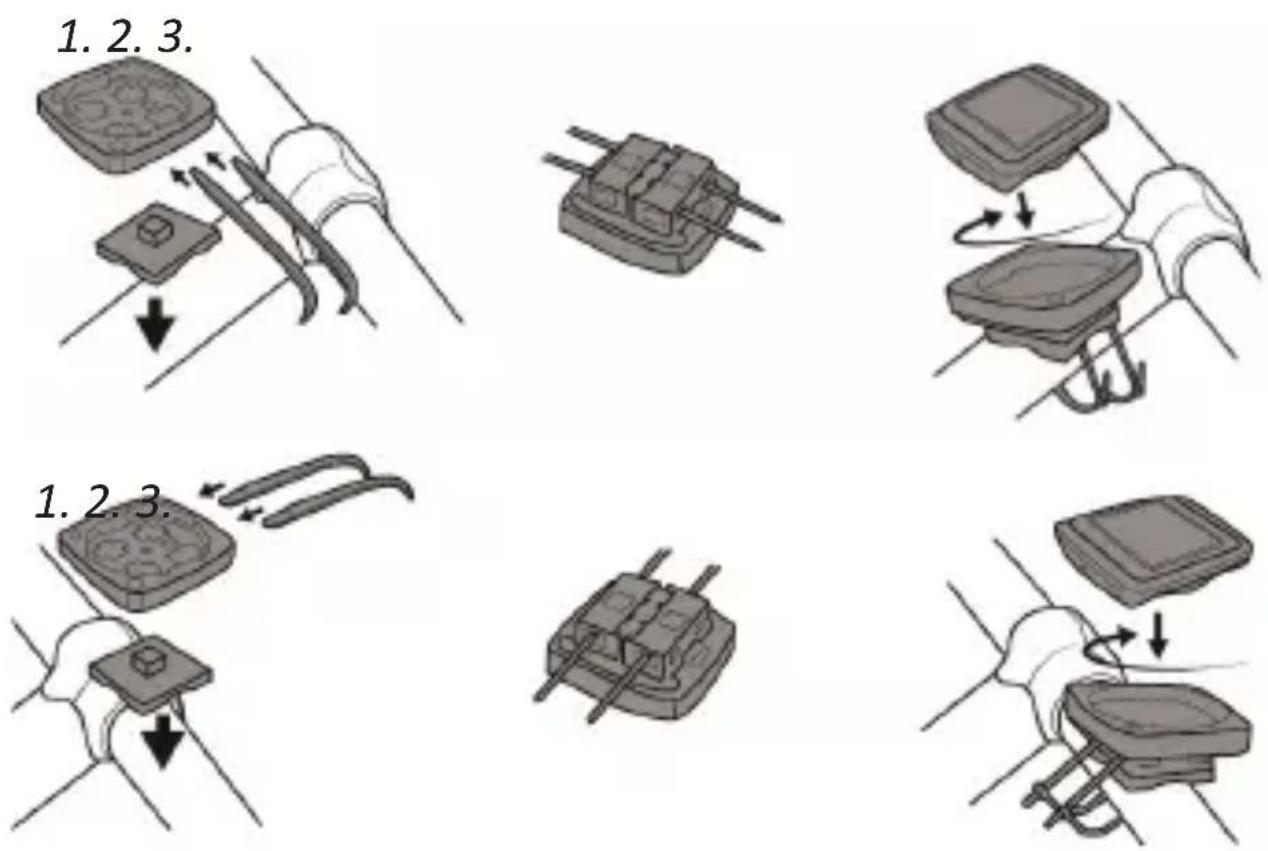
Installing the bracket
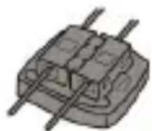
Mount the bracket as shown in the following illustrations. Make sure that you can fix the bracket in two different positions. To do this, consult the correct diagram. After mounting, cut off any remaining edges on the cable tie to avoid injuries.
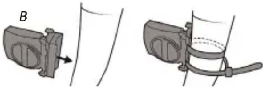
Installing the wireless transmitter
Place the sensor on the wheel fork and fix the sensor using the cable ties provided. The sensor side of the transmitter should point towards the spokes. Ensure that the sensor makes contact with the spokes.
natural_image
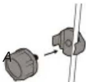
Mechanical assembly diagram showing two views of a device with a labeled component 'B' (no text or symbols present)Installing the magnet
Unscrew the magnet from the magnet holder. Then place the plastic plate with the guide at the top in a spoke. Screw the magnets and the nut onto the plastic plate so that the spoke is tightened.
natural_image
Diagram showing two mechanical components with an arrow indicating motion, no text or symbols presentThe complete installation of the sensor and magnet is displayed in the following:
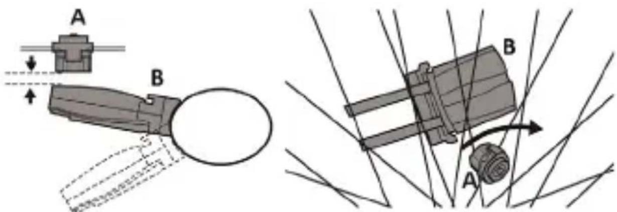
Note: The minimum distance between the magnet and transmitter should be less than 5 mm to ensure optimum transmission. Adjust the magnet accordingly.
5. Commissioning
We recommend that you reset the device once before using it. To do so, remove the battery and press the "Reset" button using a thin object (e.g., a screwdriver).
Settings
There are two ways to access the system settings.
- The system settings can be accessed when the battery is replaced or newly inserted.
- Press the "Set (S)" button and the "Down(-)" button in clock mode for 2 seconds in the home screen.
Press the "SET" button to change the current value. To adjust the value, press the "Up (+)" and "Down (-)" buttons. Press the "MODE" button to access the next setting menu.
The setting sequence is as follows: Language->User profile->Wheel circumference ->Unit of range and speed->Age->Unit of weight->Weight->Time format ->Time->CO2 savings->Service interval->Unit of temperature
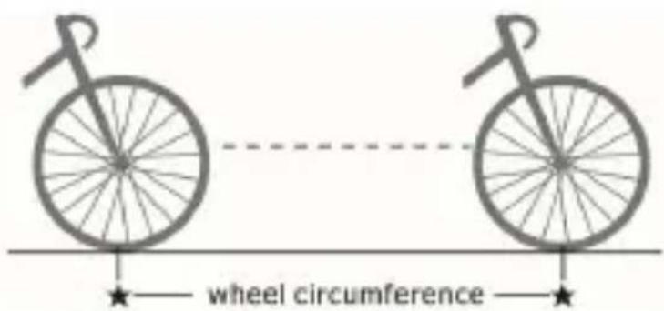
Note: Measure the wheel circumference (WS) before specifying it. The following measurement methods can be used:
- Note the selected size of the wheel and refer to the table below to find the appropriate circumference.
- Mark a point on the desired bicycle tyre and push the bicycle forward until the tyre rotates once. The wheel circumference is the distance covered.
Ensure that the wheel circumference is precise, as this will significantly affect the accuracy of the measured data.
An example for measurement method 1:
Wheel circumference table
| Tyre average value Wheel circumference value (in mm) | |
| 26 inch 57-559 2100 | |
| 26 inch 37-590 2090 | |
| 26 inch 60-559 2150 | |
| 27 inch 32-630 2180 | |
| 28 inch 20-622 2110 | |
| 28 inch 25-622 2130 | |
| 28 inch 30-622 2260 | |
| 28 inch 35-622 2185 | |
| 28 inch 37-622 2190 | |
| 28 inch 40-622 2220 | |
| 28 inch 42-622 2230 | |
| 28 inch 47-622 2280 | |
| 28 inch 50-622 2280 | |
| 28 inch 54-622 2295 | |
| 28 inch 60-622 2350 | |
| 28 inch 40-635 2240 | |
| 20 inch 40-406 1530 | |
| 20 inch 54-406 1590 | |
| 24 inch 47-507 1860 | |
| 24 inch 54-507 1920 | |
| 26 inch 25-559 1940 | |
| 26 inch 40-559 2000 | |
| 26 inch 50-559 2040 | |
6. Functions
Function Menu "Up (+)" button (advanced profile)
The following functions can be accessed using the "Up (+)" button. You can scroll through the respective menu items by repeatedly pressing the "Up (+)" button.
Time
The current time in 12 or 24 hour mode is displayed here.
Total distance covered (total KM)
This mode provides information about the total distance covered in kilometres.
Total trip time (total TM)
The total trip time since the last reset is shown in the display in this mode. The time stops as soon as you stop the trip. It resumes again if you continue the trip.
Temperature (degrees)
The ambient temperature is displayed.
Stop watch
Press the "SET (S)" button to start or stop the stopwatch. The stopwatch is reset if you press and hold the "SET" button for 3 seconds. This function works only in the stopwatch mode.
Cal rate
Displays the calories currently being burnt.
Calories (calorie)
Calories display.
Fat
Displays the fat currently being burnt.
CO2 KG
Displays the current utilised emissions that were saved.
KM + / -
Depending on the setting, the incremented or decremented kilometres. Press and hold the SET button (S) to adjust the kilometre settings. Press the "SET" button to change the current value. To adjust the value, press the "Up (+)" and "Down (-)" buttons. To close the settings after configuring them, press the "MODE" button (M).
Timer + / -
Depending on the setting, the incremented or decremented time. Press and hold the SET button (S) to adjust the timer settings. Press the "SET" button to change the current value. To adjust the value, press the "Up (+)" and "Down (-)" buttons. To close the settings after configuring them, press the "MODE" button (M).
Scan mode
The "scan" mode changes automatically every 4 seconds between the actual trip distance, the trip time, the maximum speed (MXS), and the average speed.
Function Menu "Mode (M)" button (basic profile)
Day kilometres (Day-KM / TRIPDIST)
Displays the kilometres covered in the current trip
Maximum speed (max-KmH / MAXSPEED)
The maximum speed since the last reset is recorded here and shown in the display.
Average speed (Ave-KM / AVGSPEED)
This mode records the average speed since the last reset and shows this in the display. The average speed is calculated using the distance covered and dividing it by the ride time.
Trip time (trip time / TRIPTIME)
The total trip time of the current trip is shown here.
Scan mode
The "scan" mode changes automatically every 4 seconds between ride time (RTM), distance covered (DST), maximum speed (MXS), and average speed (AVS).
6.1. Custom mode
Using the custom mode, you can switch certain displays on or off according to your requirements.
Press and hold the "Mode (M)" button for about 4 seconds until the profile is displayed. Go to the "Basic" mode using the "Up (+)" and "Down (-)" buttons. Press the "Set (S)" button once, until the word "Advanced" starts flashing. Press and then hold the "Set (S)" button until you access the Custom menu. The display now shows the "Time". Press the "Set (S)" button.
The text "OFF" is illuminated below "Time". You can now choose between "ON" and "OFF" using the "Up(+)" and "Down (-)" buttons. Select "ON" if you want to switch on the display in your custom mode. Select "OFF" to switch off this function. The setting cycle is as follows: Time -> Total KM -> Total TM -> Degrees -> Stopwatch -> Cal rate -> Calorie -> Fat -> CO2 KG -> KM +/- -> Timer +/- -> Scan
You can then access the display points set using "ON" using the "Up (+)" button. Press the button again to switch between your selected displays.
6.2. Turning on the backlight
Press the "Down (-)" button to turn on the backlight. The backlight turns off automatically after about 5 seconds.
7. Buttons and functions
Mode (M) button:
Using the "MODE" button, you can switch between the different functions or access the profile settings.
Set (S) button:
The values in the settings can be adjusted using the "SET" button or, for example, you can start the built-in stopwatch.
UP (+) button:
The values in the setting can be changed using the "UP (+)" button.
Down (-) button:
The values in the setting can be changed using the "DOWN (-)" button.
Resetting:
Press and hold the "Mode (M)" button and the UP (+) button simultaneously for about 5 seconds. "RESET" appears on the display. This text than starts flashing and it can be confirmed using the "SET (S)" button to reset the device.
Sleep mode:
The bicycle computer starts the sleep mode (auto ON/OFF) if it does not receive any signal after about 4 minutes. Alternatively, you can enable the sleep mode by pressing and holding the "Down (-)" and "UP (+)" buttons simultaneously for about 4 seconds.
As soon as the sensor inside the computer detects a movement, it switches on automatically and receives data from the Reed sensor.
8. Replacing the battery
Replace the batteries when the battery icon appears on the display or the display becomes difficult to read. Before replacing the batteries, ensure that (if desired) you note the total distance covered (TOT DIST) and the total ride time (TOT TIME), as these values are reset when the battery is replaced.
You can then open the battery compartment at the back and replace the battery. Only use CR2032 batteries. In addition, ensure that the battery polarity is correct when inserting. The positive pole of the battery should point towards the battery cover. Then close the battery compartment again.
Note! Caution!
9. Additional information about this device
- The bicycle computer can be used on rainy days. However, it should under no circumstances be immersed in water.
- Do not leave the bicycle computer unattended on the bicycle.
- Protect the device against bright sunlight.
- Check the distance between the sensor and the magnet at regular intervals.
- Do not use alcohol or any aggressive or chemical cleaning agents to clean the device.
- Pay attention to the traffic while riding. Do not allow yourself to be distracted by the bicycle computer.
10. Troubleshooting
Problem Cause of error Troubleshooting
| Display is black | The bicycle computer may have been exposed to the sun for too long | Store the bicycle computer in a shady and cool place when it is not being used. |
| Display refreshes slowly | The ambient temperature is too low | Store the device so that it is not exposed to extreme temperatures. |
| Display is off | Battery is lowBattery is inserted incorrectly | Replace the batteryInsert the battery correctly |
| Problem Cause of | error Troubleshooting | |
| Speed is not displayed or displayed incorrectly | Distance between magnet and sensor is too greatSensor not mounted properlyConfigured wheelcircumference is incorrect | Reduce the distance between magnet and sensor (max 60 cm)Check the sensor position and adjust if necessaryMeasure the wheelcircumference again and correct it |

11. Safety instructions and disclaimer
Never try to open the device to carry out repairs or modifications. Avoid contact with the mains voltage. Do not short-circuit the product. The device is not approved for outdoor use. Therefore please use it only in dry surroundings. Protect it from high humidity, water and snow. Do not expose the device to high temperatures. Do not expose the device to sudden changes in temperature or strong vibrations, as this could damage the electronic components. Check the device for damage before using it. The device should not be used if it has been subject to impact or has been damaged in any other manner. Please comply with the local regulations and restrictions. Do not use the device for purposes other than those described in the user manual. This product is not a toy. Keep it out of the reach of children or mentally disabled persons. Any repair or modification to the device, which is not carried out by the original supplier, will void any warranty and guarantee claims. The device should only be used by those who have read and understood this user manual. The specifications of the device may be changed without special prior notification.

12. Disposal instructions
In line with the European WEEE directive, electrical and electronic devices should not be disposed of along with domestic waste. Their components have to be sent separately for recycling or disposal, as improper disposal of toxic and dangerous components may permanently damage the environment. According to the electrical and electronic equipment act (ElektroG), you are obliged (as a consumer) to return (free of charge) all electrical and electronic devices to the manufacturer, the point of sale, or public collection points at the end of their service life. The relevant local laws regulate the details in this regard. The symbol on the product, in the user manual or/and the packaging refers to these regulations. With this manner of sorting, recycling and disposal of used devices, you make an important contribution towards protecting our environment.

13. Instructions for battery disposal
In conjunction with the sale of batteries along with the supply of devices that include batteries, the supplier is obliged to point out the following to the customer:
The customer is legally obliged to return used batteries. He can return used batteries which the supplier offers or has offered as new batteries in his assortment free of charge to the supplier's dispatch warehouse (shipping address). The symbols shown on the batteries mean the following: Pb = battery contains more than 0.004 percent lead by weight, Cd = battery contains more than 0.002 percent cadmium by weight, Hg = battery contains more than 0.0005 percent mercury by weight.
The symbol of the crossed-out dustbin means that the battery must not be disposed of in household waste.
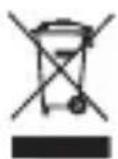
WEEE Guideline: 2012/19/EU
WEEE Register no.: DE 67896761
The company WD Plus GmbH hereby certifies that the device 303208/20190304FZ002 complies with the fundamental requirements and all other relevant stipulations of the guideline 2014/53/EC. A complete conformity statement can be obtained from: WD Plus GmbH, Wohlenbergstraße 16, 30179 Hannover
Touche SET (S) Touche MODE (M)

natural_image
Diagram of a bicycle wheel assembly with a sensor and wheel (no text or labels)Placer la batterie
Unité principale
Installation du support
natural_image
Mechanical assembly diagram showing two views of a device with labeled component B (no text or symbols present)natural_image
Diagram showing two mechanical components connected by a rod, with an arrow indicating motion (no text or symbols present)natural_image
Diagram of a bicycle wheel assembly with labeled components (no text or symbols present)natural_image
Mechanical assembly diagram showing two components with a labeled part B, no text or symbols presentnatural_image
Diagram showing two mechanical components with an arrow indicating a joint or connection (no text or symbols present)natural_image
Diagram of a mechanical device with labeled components A and B, showing motion lines without any text or symbols.| Sezione ruota Valore circonferenza ruota (in mm) | |
| 26 pollici 57-559 2100 | |
| 26 pollici 37-590 2090 | |
| 26 pollici 60-559 2150 | |
| 27 pollici 32-630 2180 | |
| 28 pollici 20-622 2110 | |
| 28 pollici 25-622 2130 | |
| 28 pollici 30-622 2260 | |
| 28 pollici 35-622 2185 | |
| 28 pollici 37-622 2190 | |
| 28 pollici 40-622 2220 | |
| 28 pollici 42-622 2230 | |
| 28 pollici 47-622 2280 | |
| 28 pollici 50-622 2280 | |
| 28 pollici 54-622 2295 | |
| 28 pollici 60-622 2350 | |
| 28 pollici 40-635 2240 | |
| Sezione ruota Valore circonferenza ruota (in mm) |
| 20 pollici 40-406 1530 |
| 20 pollici 54-406 1590 |
| 24 pollici 47-507 1860 |
| 24 pollici 54-507 1920 |
| 26 pollici 25-559 1940 |
| 26 pollici 40-559 2000 |
| 26 pollici 50-559 2040 |
6. Funzioni
natural_image
Diagram of a bicycle wheel assembly with a sensor and wheel (no text or labels)Colocar la pila
natural_image
Diagram showing a mechanical component with rotating parts and a coin-like element (no text or symbols)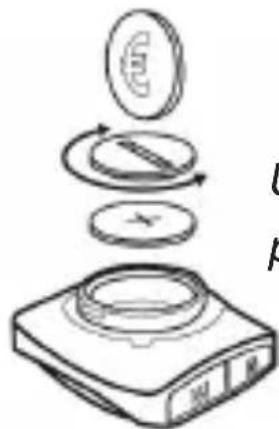
Unidad principal
natural_image
Diagram showing mechanical components with arrows indicating motion or force direction (no text or symbols)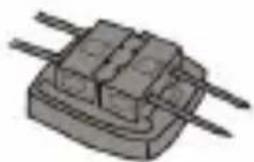
natural_image
Illustration of a mechanical component with two parallel rods (no text or symbols)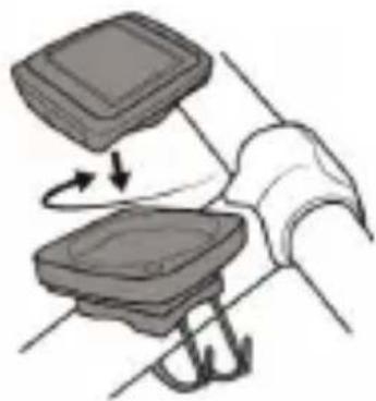
natural_image
Diagram showing a mechanical assembly with a clamped component and directional arrows (no text or symbols)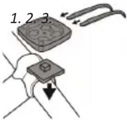
natural_image
Illustration of a mechanical component with two rods (no text or symbols)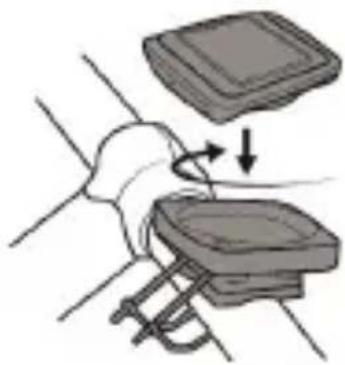
natural_image
Illustration of a hand pressing down on a mechanical component with arrows indicating motion (no text or symbols)natural_image
Mechanical assembly diagram showing two views of a device with labeled component B (no text or symbols present)natural_image
Diagram showing two mechanical components connected by a rod, with an arrow indicating motion (no text or symbols present)


- Table of contents
- Batterie einlegen
- Installation des Magnets
- Funktionen
- Scope of delivery
- Technical data
- Product details
- Installation and Assembly
- Insert the battery
- Installing the bracket
- Installing the wireless transmitter
- Installing the magnet
- Commissioning
- Settings
- Functions
- Function Menu "Up (+)" button (advanced profile)
- Time
- Total distance covered (total KM)
- Total trip time (total TM)
- Temperature (degrees)
- Stop watch
- Cal rate
- Calories (calorie)
- Fat
- CO2 KG
- KM + / -
- Timer + / -
- Scan mode
- Turning on the backlight
- Buttons and functions
- Mode (M) button:
- Set (S) button:
- UP (+) button:
- Down (-) button:
- Resetting:
- Sleep mode:
- Replacing the battery
- Note! Caution!
- Additional information about this device
- Troubleshooting
- Problem Cause of error Troubleshooting
- Safety instructions and disclaimer
- Disposal instructions
- Instructions for battery disposal
- Placer la batterie
- Installation du support
- Funzioni
- Colocar la pila
Brand : Aplic
Model : 303208
Category : Meter