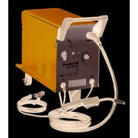
BT-GW 150 - Welding machine EINHELL - Free user manual and instructions
Find the device manual for free BT-GW 150 EINHELL in PDF.


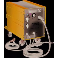
| Product type | MIG/MAG welding machine |
| Brand | Einhell |
| Model | BT-GW 150 |
| Supply voltage | 230 V ~ 50 Hz |
| Welding current | 25 - 120 A (max. 150 A) |
| Solid wire diameter | 0.6 / 0.8 mm |
| Weight | 25 kg |
| Shielding gas | CO₂ or Ar/CO₂ mixture |
| Recommended gas flow rate | 5 - 15 l/min |
| Wire spool capacity | Max. 5 kg |
| Duty cycle (at 40 °C) | 120 A at 10% / 90 A at 20% / 75 A at 30% / 52 A at 60% / 40 A at 100% |
| Protection class | IP21 |
| Thermal protection | Yes, with indicator light |
| Recommended fuse | 16 A |
| Welding process | MAG (active gas arc welding) |
| Weldable materials | Non-alloy steels |
| Included accessories | Torch, gas nozzle, welding screen with glass, pressure regulator, gas hose, ground cable, set of rollers and contact tubes |
| Maintenance | Clean with a damp cloth and a little soap; do not use solvents |
| Warranty | 12 months (commercial use) / 24 months (private use) |
Frequently Asked Questions - BT-GW 150 EINHELL
User questions about BT-GW 150 EINHELL
0 question about this device. Answer the ones you know or ask your own.
Ask a new question about this device
Download the instructions for your Welding machine in PDF format for free! Find your manual BT-GW 150 - EINHELL and take your electronic device back in hand. On this page are published all the documents necessary for the use of your device. BT-GW 150 by EINHELL.
USER MANUAL BT-GW 150 EINHELL
natural_image
Interior view of an electronic device casing with labeled components (no text or symbols visible)
natural_image
Black plastic mechanical component with labeled parts (s, q) and mounting holes, no readable text or symbols beyond labels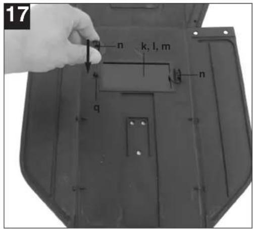
natural_image
Top-down view of a black plastic boat hull with visible structural ribs and mounting holes (no text or symbols)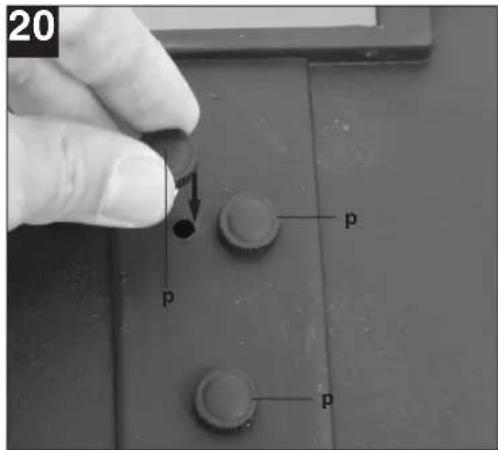
natural_image
Close-up of a hand using a mechanical switch to interact with a device, showing no visible text or symbols.

7
natural_image
Close-up of a mechanical component with labeled part G, showing bolted and threaded features (no readable text or symbols beyond label)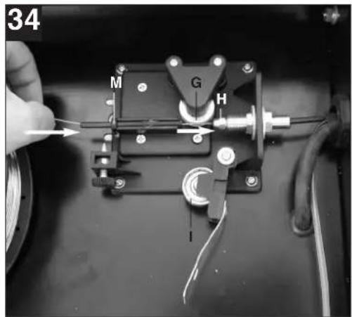
natural_image
Close-up of a gloved hand holding a small mechanical component with wire and screw, next to a circular object (no visible text or symbols)Inhaltsverzeichnis:
- Safety regulations
- Layout and items supplied
- Intended use
- Technical data
- Before starting the equipment
- Operation
- Cleaning, maintenance and ordering spare parts
- Disposal and recycling
- Troubleshooting
- Key to symbols
⚠️ Important!
When using the equipment, a few safety precautions must be observed to avoid injuries and damage. Please read the complete operating instructions and safety regulations with due care. Keep this manual in a safe place, so that the information is available at all times. If you give the equipment to any other person, hand over these operating instructions and safety regulations as well. We cannot accept any liability for damage or accidents which arise due to a failure to follow these instructions and the safety instructions.
1. Safety regulations
The corresponding safety information can be found in the enclosed booklet.
2. Layout and items supplied (Fig. 1-8)
- Handle
- Operating status indicator
- Thermostat control lamp
- Housing cover
- Gas bottle support surface
- Castors
- ON/OFF/Welding current switch
- Supporting foot
- Mains plug
- Earth terminal
- Hose package
- Gas nozzle
- Burner
- Welding wire speed controller
- Belt strap
- Gas supply connector
- Welding screen
- Shielding gas hose
- Pressure reducer
- Pressure gauge
- Screw connector
- Safety valve
- Shielding gas hose connector
- Rotary knob
- Burner switch
- 2 x contact pipe
2.1 Assembly material
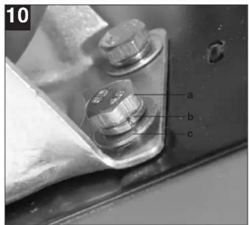
a. 8 x Screw for castors
b. 8 x Spring ring for castors
c. 8 x Washer for castors
d. 4 x Screw for handle
e. 4 x Spring ring for handle
f. 4 x Washer for handle
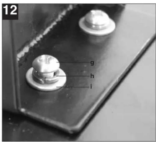
g. 2 x Screw for supporting foot
h. 2 x Spring ring for supporting foot
i. 2 x Washer for supporting foot
j. 2 x Hose clip
k. 1 x Safety glass frame
I. 1 x Welding glass
m. 1 x Transparent safety glass
n. 2 x Safety glass retaining bushes
o. 3 x Nut for handle
p. 3 x Screws for handle
q. 2 x Safety glass retaining pin
r. 1 x Handle
s. 1 x Welding screen frame
3. Intended use
The shielding gas welding set is exclusively designed for welding steel with the MAG (Metal Active Gas) method using the appropriate welding wires and gases.
The machine is to be used only for its prescribed purpose. Any other use is deemed to be a case of misuse. The user / operator and not the manufacturer will be liable for any damage or injuries of any kind caused as a result of this.
Important information about the power connection
This equipment falls under Class A of the standard EN 60974-10, i.e. it is not designed for use in residential areas in which the power supply is based on a public low-voltage supply system because given unfavorable conditions in the power supply the equipment may cause interference. If you want to use the equipment in residential areas in the which the power supply is based on a public low-voltage supply system, you must use an electromagnetic filter which reduces the electromagnetic interference to the point where the user no longer notices any disturbance.
In industrial parks or other areas in which the power supply is not based on a public low-voltage supply system the equipment can be used without such a filter.

GB
General safety information
It is the user's responsibility to install and use the equipment properly in accordance with the instructions issued by the manufacturer. If electromagnetic interference is noticed, it is the user's responsibility to eliminate said interference with the technical devices mentioned in the section "Important information about the power connection".
Reduction of emissions
Main current supply
The welder must be connected to the main current supply in accordance with the instructions issued by the manufacturer. If interference occurs, it may be necessary to introduce additional measures, e.g. fitting a filter to the main current supply (see above in the section "Important information about the power connection"). The welding cables should be kept as short as possible.
Pacemakers
Persons using an electronic life support device (e.g. a pacemaker) should consult their doctor before they go near electric sparking, cutting, burning or spot-welding equipment in order to be sure that the combination of magnetic fields and high electric currents does not affect their devices.
For commercial users the guarantee period is 12 months and for normal users 24 months, beginning from the date of purchase.
4. Technical data
Mains connection: 230 V \~ 50 Hz
Welding current: 25-120 A (max. 150 A)
| Duty cycle X% 10 20 30 | 60 | 100 | |||||
| Welding current I_2 (A): | 1 | 20 | 90 | 75 | 52 | 40 | 25 |
| Rated idling current U_0 : | 48 | ||||||
Max. welding wire drum: 5 kg
Welding wire diameter 0.6/0.8 mm
| Fuse: | 16 |
| Weight: | 25 |
The welding times apply for an ambient temperature of 40^ C.
5. Before starting the equipment
5.1 Assembly (Fig. 5-21)
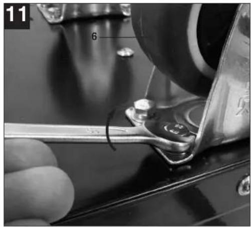
5.1.1 Fitting the castors (6)
Fit the castors (6) as shown in Figures 7, 9, 10 and 11.
5.1.2 Fitting the supporting foot (8)
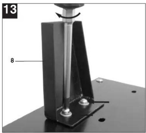
Fit the standing foot (8) as shown in Figures 7, 9, 12 and 13.
5.1.3 Fitting the handle (1)
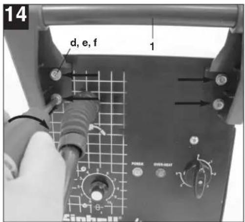
Fit the handle (1) as shown in Figures 7 and 14.
5.1.4 Fitting the welding screen (17)
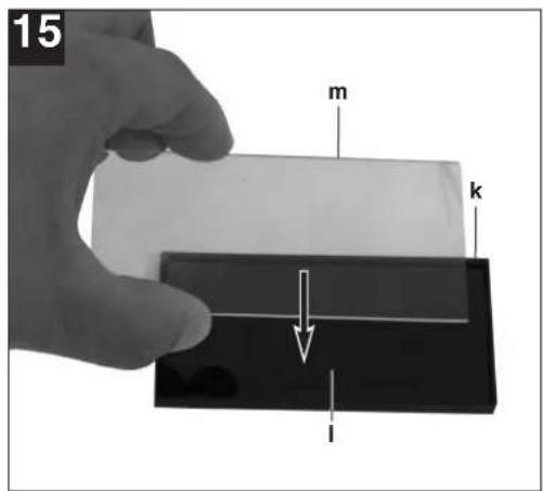
- Place the welding glass (l) and the transparent safety glass (m) over it in the frame for the safety glass (k) (Fig. 15).
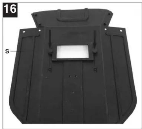
- Press the safety glass retaining pins (q) into the holes in welding screen frame (s) from the outside. (Fig. 16)
- Place the frame for the safety glass (k) with the welding glass (l) and transparent safety glass (m) from the inside into the recess in the welding frame (s), press the safety glass retaining bushes (n) on to the safety glass retaining pins (q) until they engage to secure the frame for the safety glass (k). The transparent safety glass (m) must be on the outside. (Fig. 17)
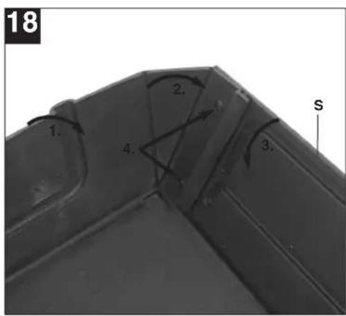
- Bend the top of the welding screen frame (s) inwards (Fig. 18/1) and fold down the top corners (Fig. 18/2). Now bend the outer sides of the welding screen frame (s) inwards (Fig. 18/3) and connect them by pressing the top corners and outer sides together. As the retaining pins engage, you should be able to hear two clear clicks on each side (Fig. 18/4).
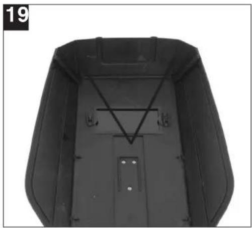
- When the top corners of the welding screen are connected as shown in Figure 19, place the screws for the handle (p) from the outside through the three holes in the welding screen. (Fig. 20)
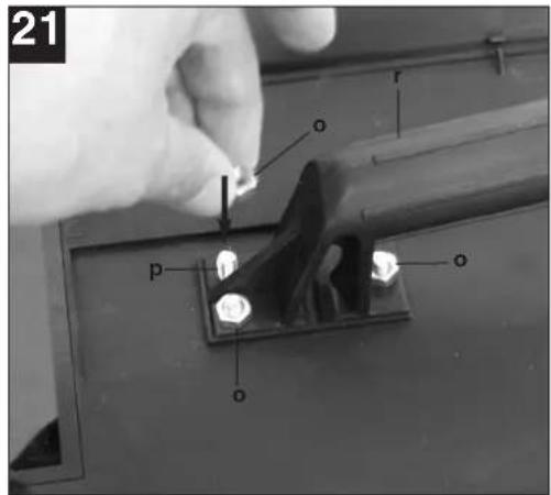
- Turn over the welding screen and place the handle (r) over the threads on the three screws for the handle (p). Secure the handle (r) to the welding screen the three nuts for the handle (o) (Fig. 21).
GB
5.2 Gas connection (Fig. 4, 5, 22-27)
5.2.1 Gas types
Gas shielding is required for welding with continuous wire, the composition of the shielding gas depends on the welding method you wish to use.
| Shielding gas CO2 Argon/CO2 | ||
| Metal to be welded | ||
| Non-alloyed steel X X |
5.2.2 Fitting the gas bottle on the unit (Fig. 22-23)
The gas bottle is not supplied.
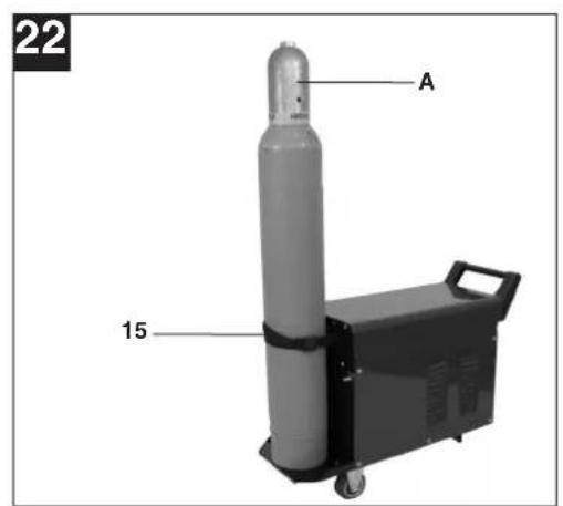
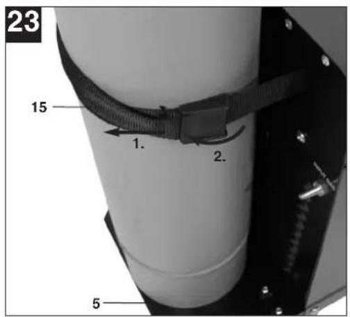
Fit the gas bottle as shown in Figures 22–23. Ensure that the belt strap (15) is secure and that the welding set cannot tip over.
Important. Only gas bottles with a maximum capacity of 10 liters may be fitted on the gas bottle support area (Fig. 23/5). If you wish to use larger gas bottles, there is a risk that they will tip over and therefore they may only be placed next to the unit. In this case the gas bottle must be secured to prevent it tipping over.
5.2.3 Connecting the gas bottle (Fig. 7, 24-27)
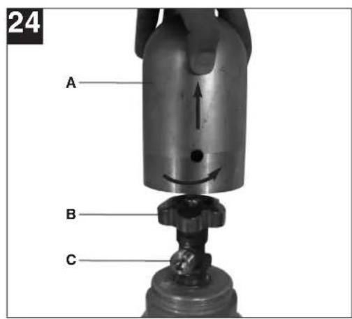
After removing the protective cap (Fig. 24/A), open the bottle valve (Fig. 24/B) briefly, ensuring it is pointing away from your body.
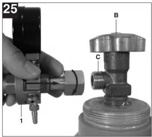
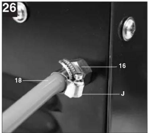
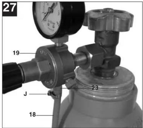
Clean any dirt off the connecting thread (Fig. 24/C) if necessary using a dry cloth without adding any cleaning products. Check whether there is a seal on the pressure reducer (19) and that it is in perfect condition. Turn the pressure reducer (19) clockwise on to the connection thread (Fig. 25/C) on the gas bottle (Fig. 25). Place the two hose clips (j) over the shielding gas hose (18). Connect the shielding gas hose (18) to the shielding gas hose connection (23) on the pressure reducer (19) and gas supply connector (16) on the welding set and secure it to both connectors using the hose clips (j). (Fig. 26-27) Important. Check all gas and other connection for leaks. Check the connections using leak spray or soap suds.
5.2.4 Information about the pressure reducer (Fig. 4/19)
The gas delivery rate can be adjusted using the rotary knob (24). The set gas delivery rate can be read off the pressure gage (20) in liters per minute (l/min). The gas is discharged at the shielding gas hose connector (23) and is then forwarded to the welding set through the shielding gas hose (Fig. 3/18). (see 5.2.3)
Important. Always proceed as described in point 6.1.3 for setting the gas delivery rate.
The pressure reducer is fitted on the gas bottle using the screw connector (21) (see 5.2.3).
Important. The pressure reducer may only be adjusted and repaired by trained personnel. Send defective pressure reducers to the service address if necessary.
5.3 Mains connection
● Before you connect the equipment to the mains supply make sure that the data on the rating plate are identical to the mains data.
● The equipment may only be operated from properly earthed and fused shock-proof sockets.
5.4 Fitting the wire spool (Fig. 1, 5, 6, 28 - 36)
The wire spool is not supplied.
5.4.1 Wire types
Various welding wires are required for different applications. The welding set can be used with welding wires with a diameter of 0.6 and 0.8 mm. The appropriate feed rollers and contact tubes are supplied with the set. The feed roller, contact tube and wire cross-section must always match each other.
5.4.2 Wire spool capacity
Wire spools with a maximum weight of 5 kg can be fitted in the welding set.
5.4.3 Inserting the wire spool
● Open the housing cover (Fig. 1/4)
- Check that the windings on the spool do not overlap so as to ensure that the wire can be unwound evenly.
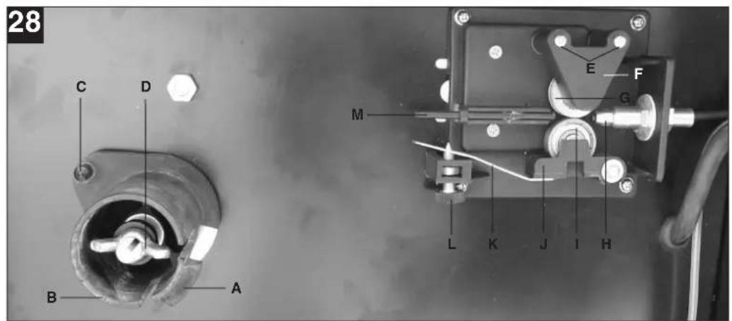
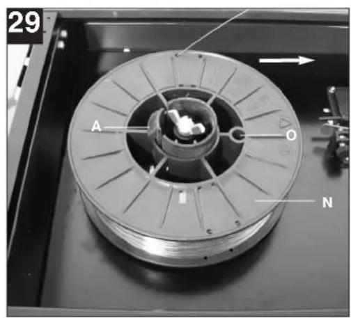
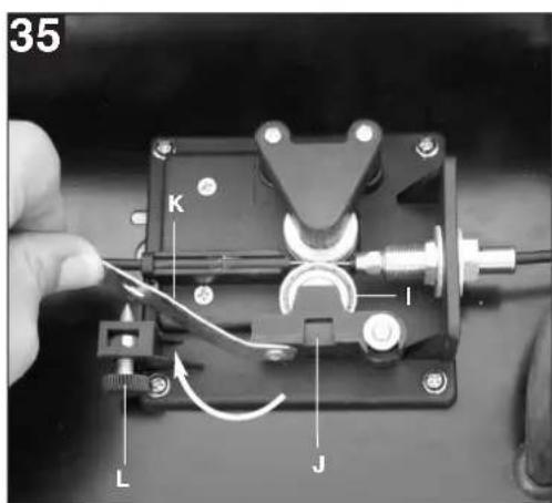
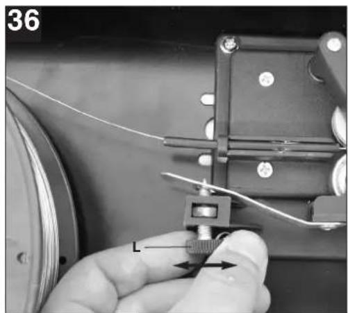
Description of the wire guide unit (Fig. 28-36)
A Spool lock
B Spool holder
C Cam pin
D Adjusting screw for roller brake
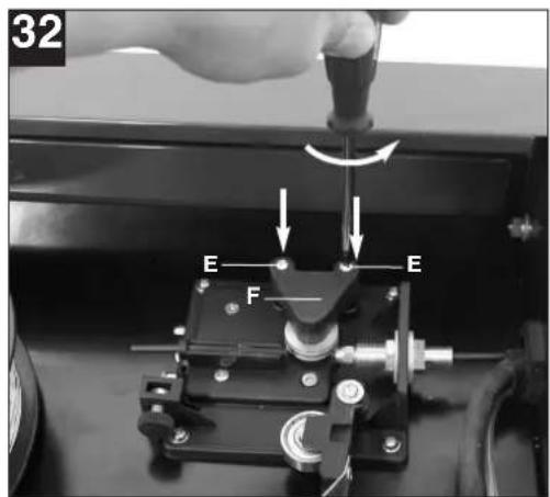
E Screws for feed roller holder
F Fee roller holder
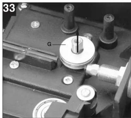
G Feed roller
H Hose package mounting
I Pressure roller
J Pressure roller holder
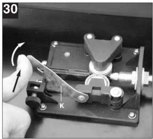
K Pressure roller spring
L Adjusting screw for counter-pressure
M Guide tube
N Wire spool
O Cam opening in wire spool
GB
Inserting the wire spool (Fig. 28, 29)
Place the wire spool (N) on the spool holder (B).
Ensure that the end of the welding wire is unwound on the side of the wire guide, see arrow.
Ensure that the spool lock (A) is pushed in and the cam pin (C) is engaged in the cam opening in the wire spool (O). The spool lock (A) must engage again over the wire spool (N). (Fig. 27)
Inserting the welding wire and adjusting the wire guide (Fig. 30-36)
● Push the pressure roller spring (K) upwards and swing it forwards (Fig. 30).
● Pull the pressure roller holder (J) with the pressure roller (I) and pressure roller spring (K) downwards (Fig. 31).
- Undo the screws for the feed roller holder (E) and pull off the feed roller holder (F) upwards (Fig. 32).
- Check the feed roller (G). The appropriate wire thickness must be specified on the top of the feed roller (G). The feed roller (G) is fitted with two guide grooves. Turn the feed roller (G) over if necessary or replace it. (Fig. 33)
- Position the feed roller holder (F) again and secure it.
- Remove the gas nozzle (Fig. 5/12) from the burner (Fig. 5/13) by turning it clockwise, unscrew the contact tube (Fig. 6/26). (Fig. 5 – 6). Place the hose package (Fig. 1/11) on the floor as straight as possible pointing away from the welding set.
● Cut off the first 10 cm of the welding wire to produce a straight cut with no shoulders, warping or dirt. Deburr the end of the welding wire.
- Push the welding wire through the guide tube (M) between the pressure and feed rollers (G/I) into the hose package mounting (H). (Fig. 34) Carefully push the welding wire by hand into the hose package until it projects out of the hose package by approx. 1 cm at the burner (Fig. 5/13).
- Undo the adjusting screw for counter-pressure (L) a few turns. (Fig. 36)
- Push the pressure roller holder (J) with pressure roller (I) and pressure roller spring (K) upwards again and attach the pressure roller spring (K) to the adjusting screw for counter-pressure (L) again (Fig. 35).
- Now set the adjusting screw for counter-pressure (L) so that the welding wire is positioned firmly between the pressure roller (I) and feed roller (G) without being crushed. (Fig. 36)
● Screw the appropriate contact tube (Fig. 6/26) for the welding wire diameter on to the burner (Fig. 5/13) and fit the gas nozzle, turning it clockwise (Fig. 5/12).
- Set the adjusting screw for the roller brake (D) so
that the wire can still be moved and the roller stops automatically after the wire guide has been braked.
6. Operation
6.1 Setting
Since the welding set must be set to suit the specific application, we recommend that the settings be made on the basis of a test weld.
6.1.1 Setting the welding current
The welding current can be set to 6 different levels using the ON/OFF/Welding current switch (Fig. 1/7). The required welding current depends on the material thickness, the required penetration depth and the welding wire diameter.
6.1.2 Setting the wire feed speed
The wire feed speed is automatically adjusted to the current setting. The final wire feed speed setting can be made on the welding wire speed controller (Fig. 1/14). We recommend that you start the setting work at level 5 which is the middle value, and then adjust it from there. The required quantity of wire depends on the material thickness, the penetration depth, the welding wire diameter and also of the size of the gap to be bridged between the workpieces you wish to weld.
6.1.3 Setting the gas delivery rate
The gas delivery rate can be infinitely adjusted on the pressure reducer (Fig. 4/19). It is shown on the pressure gage (Fig. 4/20) in liters per minute (l/min). Recommended gas delivery rate in rooms with no drafts: 5 – 15 l/min.
To set the gas flow rate, first release the clamp lever (Fig. 28/G) on the wire feed unit to prevent unnecessary wire wear (Fig. 5.4.3). Connect to the mains outlet (see point 5.3), set the ON/OFF/Welding current switch (Fig. 1/7) to setting 1 and press the burner switch (Fig. 5/25) to start the gas flow. Now set the required gas delivery rate on the pressure reducer (Fig. 4/19).
Turn the rotary knob (Fig. 4/24) counter-clockwise: Lower gas delivery rate
Turn the rotary knob (Fig. 4/24) clockwise:
Higher gas delivery rate
Secure the clamp lever (Fig. 28/G) to the wire feed unit again.
6.2 Electrical connection
6.2.1 Mains connection
See point 5.3
6.2.2 Connecting the earth terminal (Fig. 1/10) Connect the welding set's earth terminal (10) in the immediate vicinity of the welding position if possible. Ensure that the contact point is bare metal.
6.3 Welding
When all the electrical connections for the power supply and welding current circuit have been made and the shielding gas has also been connected, you can proceed as follows:
The workpieces for welding must be clear of paint, metallic coatings, dirt, rust, grease and moisture in the area where they are to be welded.
Set the welding current, wire feed and gas flow rate (see 6.1.1 - 6.1.3) as required.
Hold the welding screen (Fig. 3/17) in front of your face and move the gas nozzle to the point on the workpiece where you wish to complete the weld. Now press the burner switch (Fig. 5/25).
When the arc is burning, the welding set will feed wire into the weld pool. When the weld nugget is large enough, move the burner slowly along the required edge. Move it to and fro if necessary to enlarge the weld pool a little.
Find the ideal setting of the welding current, wire feed speed and gas delivery rate by carrying out a test weld. Ideally an even welding noise will be audible. The penetration depth should be as deep as possible, but the weld pool must not be allowed to fall through the workpiece.
6.4 Safety equipment
6.4.1 Thermostat
The welding set is fitted with an overheating guard that protects the welding transformer from overheating. If the overheating guard trips, the control lamp (3) on your set will be lit. Allow the welding set to cool for a time.
7. Cleaning, maintenance and ordering of spare parts
Always pull out the mains power plug before starting any cleaning work.
7.1 Cleaning
- Keep all safety devices, air vents and the motor housing free of dirt and dust as far as possible. Wipe the equipment with a clean cloth or blow it with compressed air at low pressure.
●We recommend that you clean the device immediately each time you have finished using it.
●Clean the equipment regularly with a moist cloth and some soft soap. Do not use cleaning agents or solvents; these could attack the plastic parts of the equipment. Ensure that no water can seep into the device.
7.2 Maintenance
There are no parts inside the equipment which require additional maintenance.
7.3 Ordering replacement parts
Please quote the following data when ordering replacement parts:
●Type of machine
●Article number of the machine
●Identification number of the machine
●Replacement part number of the part required
For our latest prices and information please go to www.isc-gmbh.info
8. Disposal and recycling
The unit is supplied in packaging to prevent its being damaged in transit. This packaging is raw material and can therefore be reused or can be returned to the raw material system.
The unit and its accessories are made of various types of material, such as metal and plastic. Defective components must be disposed of as special waste. Ask your dealer or your local council.

GB
9. Troubleshooting
| Fault Cause Remedy | ||
| Feed roller does not turn Power supply not connectedWire feed controller set to 0 | Check connectionCheck setting | |
| Feed roller turns, but does not feed any wire | Incorrect roller pressure (see 5.4.3)Roller brake set too firmly (see 5.4.3)Dirty / damaged feed roller (see 5.4.3)Damaged hose packageContact tube wrong size / dirty / worn (see 5.4.3)Welding wire welded to the gas nozzle / contact tube | Check settingCheck settingClean or replaceCheck the wire guide jacketClean or replaceRelease |
| After a lengthy period of use the welding set does not work any longer, the thermostat (3) control light is lit | The welding set has overheated due to being used for too long and a failure to observe the reset time | Leave the set to cool down for at least 20 – 30 minutes |
| Very poor weld Incorrect current / feed setting (see 6.1.1/6.1.2)No / too little gas (see 6.1.3) | Check settingCheck setting and filling pressure of the gas bottle | |
GB
10. Key to symbols
| EN 60974-1 European standard for arc welding sets and welding power supplies with limited on time | Standard for arc welding sets and welding power supplies with limited on time | Protection class |  | Do not store or use the appliance in wet or damp conditions or in the rain. |
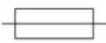 | Fuse with rated value in A in the mains connection | 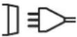 | 1-phase mains connection | |
| U_1 | Mains voltage 50 Hz Mains frequency | |||
| I_1 max Rated maximum mains current |  | Symbol for falling characteristic curve | ||
 | Read the operating instructions carefully before using the welding set and follow them |  | Metal inert and active gas welding including the use of filler wire | |
| U_0 | Rated idling voltage IP 21 | |||
| I_2 | Welding current H Insulation | exction type | ||
| ∅ mm Welding wire diameter X On-load factor | ||||
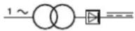 | Single-phase transformer with rectifier |
F
Subject to change without notice Wiesenweg 22, D-94405 Landau/Isar
Documents registrar: Daniel Protschka
natural_image
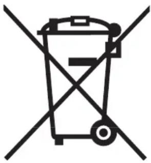
Symbol of a trash bin crossed out by two diagonal lines (no text or numbers present)©Nur für EU-Länder
Never place any electric tools in your household refuse.
To comply with European Directive 2002/96/EC concerning old electric and electronic equipment and its implementation in national laws, old electric tools have to be separated from other waste and disposed of in an environment-friendly fashion, e.g. by taking to a recycling depot.
Recycling alternative to the demand to return electrical devices:
As an alternative to returning the electrical device, the owner is obliged to cooperate in ensuring that the device is properly recycled if ownership is relinquished. This can also be done by handing over the used device to a returns center, which will dispose of it in accordance with national commercial and industrial waste management legislation. This does not apply to the accessories and auxiliary equipment without any electrical components which are included with the used device.
The reprinting or reproduction by any other means, in whole or in part, of documentation and papers accompanying products is permitted only with the express consent of ISC GmbH.
F
All of our products undergo strict quality checks to ensure that they reach you in perfect condition. In the unlikely event that your device develops a fault, please contact our service department at the address shown on this guarantee card. Of course, if you would prefer to call us then we are also happy to offer our assistance under the service number printed below. Please note the following terms under which guarantee claims can be made:
- These guarantee terms cover additional guarantee rights and do not affect your statutory warranty rights. We do not charge you for this guarantee.
- Our guarantee only covers problems caused by material or manufacturing defects, and it is restricted to the rectification of these defects or replacement of the device. Please note that our devices have not been designed for use in commercial, trade or industrial applications. Consequently, the guarantee is invalidated if the equipment is used in commercial, trade or industrial applications or for other equivalent activities. The following are also excluded from our guarantee: compensation for transport damage, damage caused by failure to comply with the installation/assembly instructions or damage caused by unprofessional installation, failure to comply with the operating instructions (e.g. connection to the wrong mains voltage or current type), misuse or inappropriate use (such as overloading of the device or use of non-approved tools or accessories), failure to comply with the maintenance and safety regulations, ingress of foreign bodies into the device (e.g. sand, stones or dust), effects of force or external influences (e.g. damage caused by the device being dropped) and normal wear resulting from proper operation of the device. This applies in particular to rechargeable batteries for which we nevertheless issue a guarantee period of 12 months.
The guarantee is rendered null and void if any attempt is made to tamper with the device.
-
The guarantee is valid for a period of 2 years starting from the purchase date of the device. Guarantee claims should be submitted before the end of the guarantee period within two weeks of the defect being noticed. No guarantee claims will be accepted after the end of the guarantee period. The original guarantee period remains applicable to the device even if repairs are carried out or parts are replaced. In such cases, the work performed or parts fitted will not result in an extension of the guarantee period, and no new guarantee will become active for the work performed or parts fitted. This also applies when an on-site service is used.
-
In order to assert your guarantee claim, please send your defective device postage-free to the address shown below. Please enclose either the original or a copy of your sales receipt or another dated proof of purchase. Please keep your sales receipt in a safe place, as it is your proof of purchase. It would help us if you could describe the nature of the problem in as much detail as possible. If the defect is covered by our guarantee then your device will either be repaired immediately and returned to you, or we will send you a new device.
Of course, we are also happy offer a chargeable repair service for any defects which are not covered by the scope of this guarantee or for units which are no longer covered. To take advantage of this service, please send the device to our service address.
F BULLETIN DE GARANTIE
Chère Cliente, Cher Client,

- Inhaltsverzeichnis:
- ⚠️ Important!
- Safety regulations
- Layout and items supplied (Fig. 1-8)
- Assembly material
- Intended use
- Important information about the power connection
- GB
- General safety information
- Reduction of emissions
- Main current supply
- Pacemakers
- Technical data
- Before starting the equipment
- Assembly (Fig. 5-21)
- Fitting the castors (6)
- Fitting the supporting foot (8)
- Fitting the handle (1)
- Fitting the welding screen (17)
- Gas connection (Fig. 4, 5, 22-27)
- Gas types
- Fitting the gas bottle on the unit (Fig. 22-23)
- Connecting the gas bottle (Fig. 7, 24-27)
- Information about the pressure reducer (Fig. 4/19)
- Mains connection
- Fitting the wire spool (Fig. 1, 5, 6, 28 - 36)
- Wire types
- Wire spool capacity
- Inserting the wire spool
- Description of the wire guide unit (Fig. 28-36)
- Inserting the wire spool (Fig. 28, 29)
- Inserting the welding wire and adjusting the wire guide (Fig. 30-36)
- Operation
- Setting
- Setting the welding current
- Setting the wire feed speed
- Setting the gas delivery rate
- Electrical connection
- Mains connection
- Welding
- Safety equipment
- Thermostat
- Cleaning, maintenance and ordering of spare parts
- Cleaning
- Maintenance
- Ordering replacement parts
- Disposal and recycling
- Troubleshooting
- Key to symbols
- F
- F BULLETIN DE GARANTIE
- Chère Cliente, Cher Client,
Brand : EINHELL
Model : BT-GW 150
Category : Welding machine