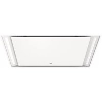
CU902554TMM - Basket Atag - Free user manual and instructions
Find the device manual for free CU902554TMM Atag in PDF.


| Product type | Decorative range hood |
| Brand | Atag |
| Model | CU902554TMM |
| Dimensions (W x D) | 847 x 487 mm (90 cm model) |
| Net weight | Approximately 30 kg |
| Electrical supply | 230 V ~ 50 Hz |
| Lighting power | LED 6 W (adjustable color temperature) |
| Suction speeds | 4 speeds + Boost function |
| Maximum normal airflow | 418 m³/h |
| Airflow in Boost | 710 m³/h |
| Noise level (normal) | 52-59 dB(A) depending on speed |
| Noise level (Boost) | 71-73 dB(A) |
| Control type | Radio remote control + touch panel |
| Connectivity | Wi-Fi 2.4 GHz, ConnectLife app |
| Filters | Washable metal grease filters (once per month) + optional charcoal filter |
| Saturation indicator | Grease filter: 30 h, charcoal filter: 120 h |
| Special functions | 10 min timer, Clean Air, light modulation (warm/cold) |
| Minimum distance above gas cooking | 65 cm |
| Safety | Automatic shut-off, remote control lock, child safety (not specified) |
| Maintenance | External cleaning with soft cloth and soapy water; filters in dishwasher |
| Repairability | LED replaced by authorized technician; spare parts available (filters, remote control) |
Frequently Asked Questions - CU902554TMM Atag
User questions about CU902554TMM Atag
0 question about this device. Answer the ones you know or ask your own.
Ask a new question about this device
Download the instructions for your Basket in PDF format for free! Find your manual CU902554TMM - Atag and take your electronic device back in hand. On this page are published all the documents necessary for the use of your device. CU902554TMM by Atag.
USER MANUAL CU902554TMM Atag
natural_image
Exterior view of a modern office building (no signage)GEBRUIKSAANWIJZING
Afzuigkap
NL
CU902554TMM
CU122554TMM
CU122754TMM
text_image
- = ≡ ≡ Wi-Fitext_image
Diagram showing a menu bar with icons for menu, menu icon, equals sign, and Wi-Fi symbol, alongside a dotted oval highlighting the equals sign.natural_image
Two white circular icons with dashed outlines on a black background, no text or symbols present.text_image
Diagram showing directional symbols including circles, arrows, and labeled points C and W on a black background
text_image
Diagram showing a grid icon with minus sign and Wi-Fi symbol, likely representing a basic wireless signal or data display.DemodusRecirculerenuitschakelen
natural_image
Two circular icons on a dark background, one with a clock-like symbol and the other with a refresh icon (no text or labels)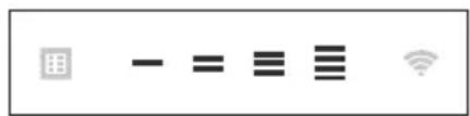
text_image
Image containing a grid icon, minus signs, equals sign, equals sign, and Wi-Fi symbol with standard icons.natural_image
Black background with white geometric shapes and central circular pattern (no text or symbols)text_image
User interface toolbar with icons for grid, minus sign, equals sign, equals sign, and Wi-Fi signaltext_image
Screenshot of a software toolbar with icons for chart, menu, equals sign, menu bar, Wi-Fi, and standard iconstext_image
Screenshot of a software toolbar with icons for grid, minus sign, equals sign, equals sign, Wi-Fi symbol, and standard iconstext_image
Diagram showing a menu bar, equality symbol, equals sign, and Wi-Fi icon with dotted outlinestext_image
Screenshot of a software toolbar with icons for menu, minus sign, equals sign, menu bar, Wi-Fi symbol, and standard iconstext_image
Row of five icons: a calendar, minus sign, equals sign, three horizontal lines, and Wi-Fi symboltext_image
Diagram showing five icons: a grid, minus sign, equals sign, three horizontal lines, and a Wi-Fi symbol.text_image
Screenshot of a software toolbar with icons for grid, minus sign, equals sign, menu bar, Wi-Fi symbol, and radio buttontext_image
Screenshot of a software toolbar with icons for grid, minus sign, equals sign, three horizontal lines, and Wi-Fi symboltext_image
Screenshot of a software toolbar with icons for grid, minus sign, equals sign, equals sign, Wi-Fi symbol, and standard icons.text_image
User interface toolbar with grid, minus sign, equals sign, equals sign, and Wi-Fi iconsWifiinschakelen:
text_image
User interface toolbar with icons for grid, minus sign, equals sign, equals sign, and Wi-Fi signaltext_image
Screenshot of a software toolbar with icons for menu, chart, equality symbols, menu bar, and Wi-Fi signalWifiuitschakelen:
text_image
User interface toolbar with icons for grid, minus sign, equals sign, equals sign, and Wi-Fi signaltext_image
Screenshot of a software toolbar with icons for menu, keyboard, equals sign, menu bar, Wi-Fi symbol, and grid interface- Raak3secondende'-(min)toetsaanomhetwifi-menuteverlaten.
Weergavevandewifi-status:
natural_image
Simple line drawing of a rectangular panel with a curved cutout and two arrows indicating direction (no text or symbols)natural_image
Illustration of a hand holding a tablet device with arrows indicating movement or force (no text or symbols)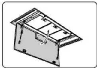
natural_image
Isometric line drawing of a mechanical housing or enclosure with internal components and mounting holes (no text or symbols)Reiniging
natural_image
Three technical illustrations: shopping cart, rolled-up cable, and a plastic waste bin (no text or symbols)natural_image
Three gray 3D-rendered objects: a shopping cart icon, a rectangular box with a slot, and a rolled document (no text or symbols)Toestelafmetingen
text_image
w l 220 213 76 203 90 l+fl w+fl| w+flI+flWliter | ||||
| 504864480840CU9055T | ||||
| 50411644801140CU125. | ||||
| 72412247001200CU127. |
Inbouwen
text_image
Min. 15 (mm) Max.50 (mm) = l (mm) = w (mm) Min. 205+5₀ (mm) max. 38 Kg| I | W | ||
| CU9055TMM | 847_± 2 | ± 2 | 21487 |
| CU1255TMM | 1147_± 2 | ± 2 | 27487 |
| CU12754TMM | 1207_± 2 | ± 2 | 38707 |
text_image
2 PH2 4x W = 484 W = 704Installatie
3

text_image
PH2 4x W = 484 W = 7044
text_image
Front connector side Front5
text_image
Tip! Max. 80mm6
text_image
Front7
text_image
PH2 4x8
natural_image
Technical line drawing of a mechanical assembly with a central circular component and directional arrows (no text or symbols)9
text_image
Technical diagram showing electrical installation with plug, socket, and power outlet connections10
text_image
CLICK11
text_image
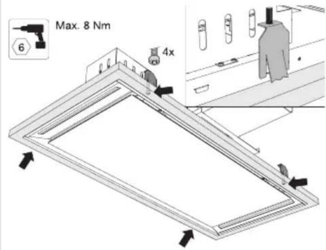
Max. 8 Nm 6 4x12
natural_image
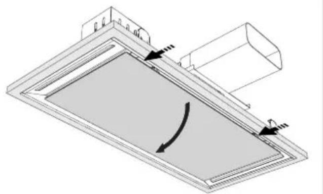
Technical diagram of a mechanical component with directional arrows indicating motion or force (no text or symbols)13
text_image
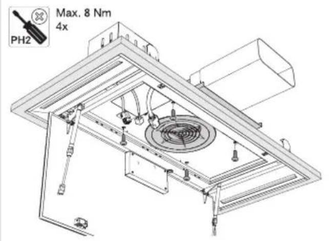
PH2 Max. 8 Nm 4x14
natural_image
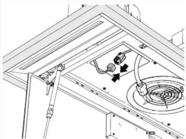
Technical line drawing of a ceiling-mounted electrical enclosure with internal components and wiring (no text or symbols)Installatie
15
natural_image
Technical line drawing of a mechanical assembly with no visible text or symbols16
text_image
4x17
natural_image
Technical diagram of an air duct system with internal components and directional arrows (no text or labels)18
natural_image
Technical line drawing of a mechanical assembly with internal components and a curved arrow indicating motion (no text or symbols)19
text_image
Diagram of a solar panel installation with labeled components and directional arrows indicating light or motion paths.text_image
Technical diagram of an industrial machine with labeled components and directional arrows indicating flow or movement.4
natural_image
Technical line drawing of a mechanical assembly with internal components and directional arrows indicating motion (no text or symbols)5
text_image
PH 2 4x6
natural_image
Technical line drawing of a mechanical assembly with a central circular component and directional arrow (no text or symbols)Installatie
7
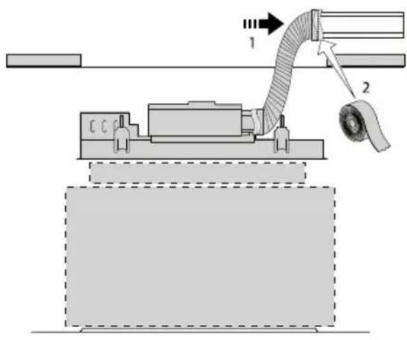
text_image
Technical diagram showing a mechanical assembly with labeled components and directional arrows indicating flow or movement.8
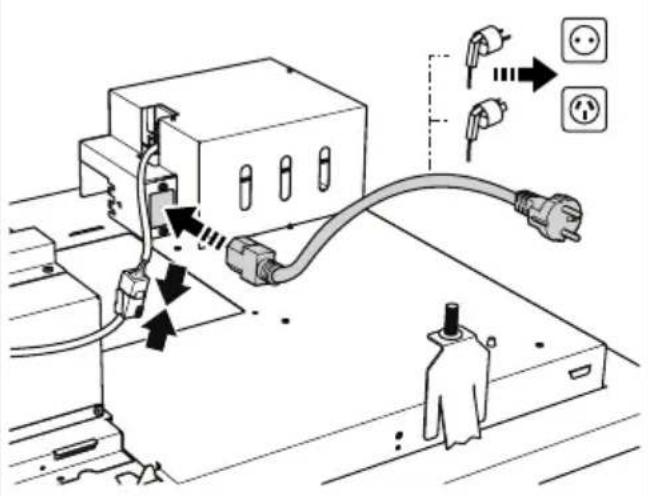
text_image
Diagram showing electrical connection with plug, socket, and power outlet, annotated with Chinese text and icons9
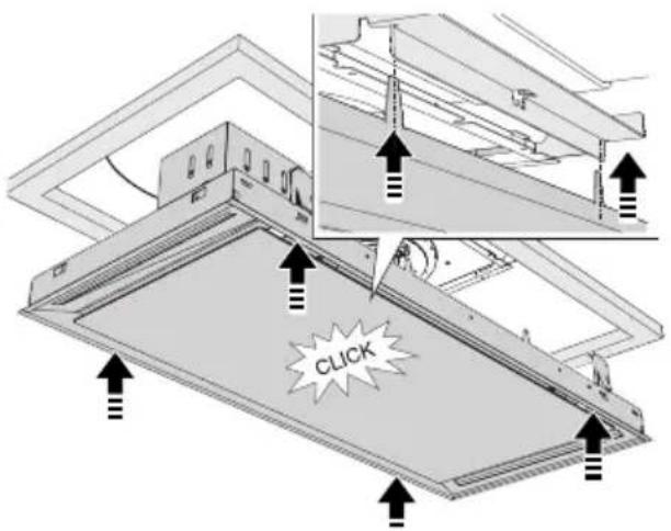
text_image
CLICK10
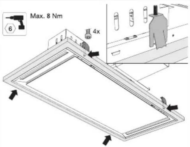
text_image
Max. 8 Nm 6 4x11
natural_image
Diagram of a rectangular panel with internal curved arrows indicating rotation or movement (no text or symbols)12
natural_image
Technical line drawing of a mechanical assembly with internal components (no text or symbols)13
natural_image
Technical line drawing of a mechanical assembly with internal components and a curved arrow indicating motion (no text or symbols)14
text_image
Diagram illustrating a device with labeled components and directional arrows, including a control panel and indicator lights.natural_image
Symbol of a trash bin with crossed lines indicating no waste, no text or labels presentnatural_image
Exterior view of a modern office building (no signage)NOTICED'UTILISATION
Hotteaspirante
FR
CU902554TMM
CU122554TMM
CU122754TMM
text_image
- = ≡ ≡ Wi-FiLahotteaspirantesemetenmarcheàlapositionderéglagelaplusbasse.
text_image
Diagram showing a menu bar with icons and a three-line menu icon, likely representing a menu or data entry.natural_image
Two white circular icons with dashed outlines on a black background, no text or symbols present.text_image
Diagram showing directional arrows and labeled points C and W with circular and dashed circles, likely from a technical or mathematical context.
text_image
Diagram showing a grid icon with minus sign and Wi-Fi signal, likely representing a basic wireless communication interface.Désactiverlemoderecyclage
natural_image
Two circular icons on a dark background, one with a clock-like symbol and the other with a refresh icon (no text or labels)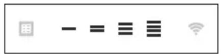
text_image
Media control icons including grid, minus sign, equals sign, equals sign, and Wi-Fi signalnatural_image
Black background with white directional arrows and a central circular symbol (no text or labels)Wi-Fi/appConnectLife
text_image
User interface toolbar with icons for grid, minus sign, equals sign, equals sign, and Wi-Fi signaltext_image
Screenshot of a software toolbar with icons for spreadsheet, Wi-Fi, and other function buttons- Après3secondes, il reviendraaumenu Wi-Fi.

text_image
Screenshot of a software toolbar with icons for grid, minus sign, equals sign, equals sign, Wi-Fi symbol, and standard icontext_image
Diagram showing five icons: a grid, minus sign, equals sign, three gray bars, and Wi-Fi symbol.text_image
Row of icons including a grid, minus sign, equals sign, menu bar, Wi-Fi symbol, and standard icontext_image
Row of five icons: grid, minus sign, equals sign, equals sign, and Wi-Fi symboltext_image
Screenshot of a software toolbar with icons for grid, minus sign, equals sign, menu, and Wi-Fi symboltext_image
Screenshot of a software toolbar with icons for grid, minus sign, equals sign, equals sign, Wi-Fi symbol, and standard icontext_image
Diagram showing a menu bar with icons for data, equality,equivation, three horizontal bars, and Wi-Fi symbol.text_image
Screenshot of a software toolbar with icons for data, menu, equals sign, three horizontal lines, and Wi-Fi symboltext_image
User interface toolbar with icons for grid, minus sign, equals sign, equals sign, and Wi-Fi signalActiverleWi-Fi:
text_image
User interface toolbar with grid, minus sign, equals sign, equals sign, and Wi-Fi iconstext_image
User interface toolbar with icons for spreadsheet, Wi-Fi, and basic arithmetic operationsDésactiverleWi-Fi:
text_image
User interface toolbar with icons for grid, minus sign, equals sign, and Wi-Fi signaltext_image
Row of five icons representing basic computer, data, math, list, and Wi-Fi symbolsnatural_image
Diagram of a rectangular panel with a curved cutout and directional arrows, no text or symbols present.natural_image
Illustration of a hand pressing down on a device panel with arrows indicating motion (no text or symbols)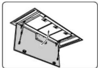
natural_image
Technical line drawing of a mechanical housing or enclosure with internal components and mounting holes (no text or symbols)Nettoyage
natural_image
Technical line drawing of a mechanical assembly with no visible text or symbols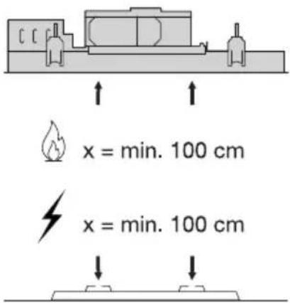
text_image
x = min. 100 cm x = min. 100 cm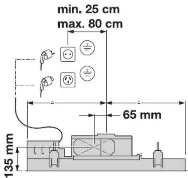
text_image
min. 25 cm max. 80 cm 65 mm 135 mmPRUDENCE!
text_image
Diagram showing three items: shopping cart, rolled-up fabric, and a trash bin with a person wearing a litter.Installationfixedescanaux
natural_image
Three gray 3D-rendered objects: a shopping cart icon, a rectangular box with a cutout, and a roll of tape (no text or symbols)Dimensionsdel'appareil
text_image
w l 220 213 76 203 90 l+fl w+fl| w+fll+flWlitre | ||||
| 504864480840CU9055T | ||||
| 50411644801140CU125. | ||||
| 72412247001200CU127. |
text_image
1 2 PH2 4x W = 484 W = 704Installation
3
text_image
PH2 4x W = 484 W = 7044
text_image
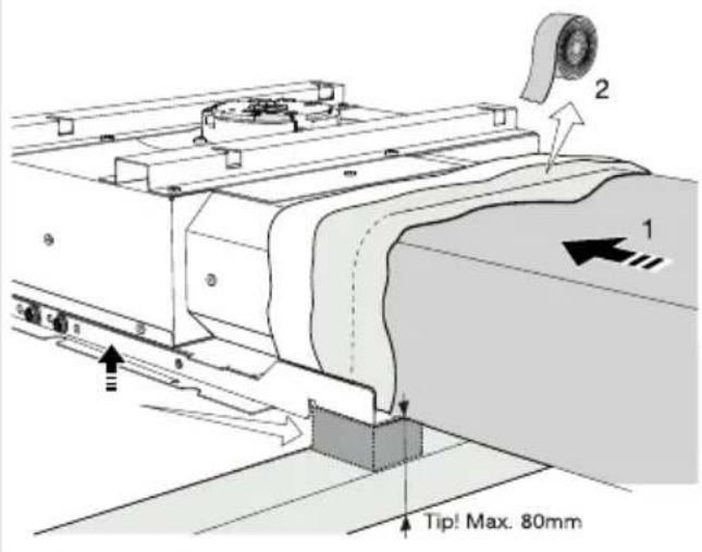
Front connector side Front5
text_image
Tip! Max. 80mm6
text_image
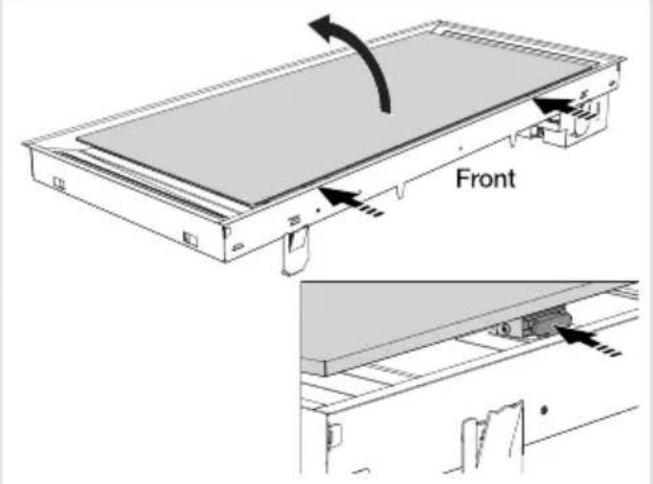
Front7
text_image
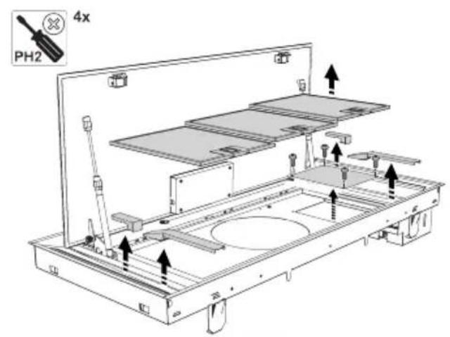
PH2 4x8

natural_image
Technical line drawing of a mechanical assembly with a rotating component and mounting bracket (no text or symbols)9
text_image
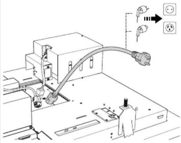
Technical diagram showing installation of an electrical outlet with power plug and socket connections, including a close-up of electrical outlets.10
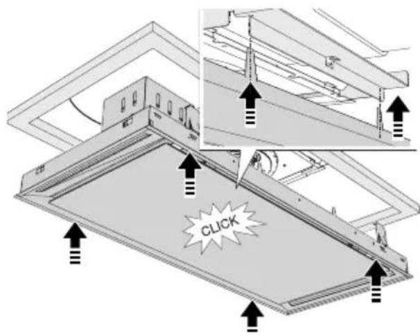
text_image
CLICK11
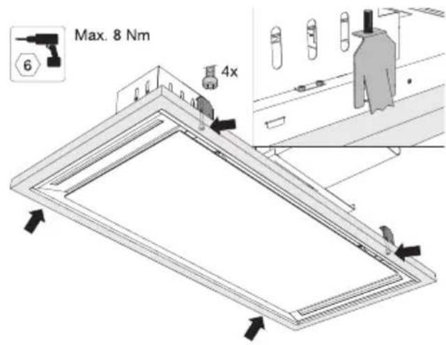
text_image
Max. 8 Nm 6 4x12
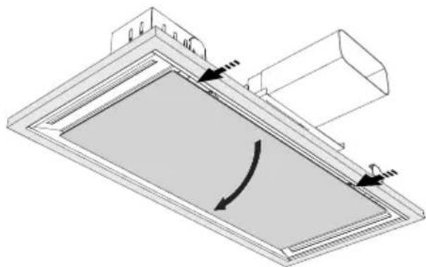
natural_image
Technical diagram of a ceiling-mounted panel with directional arrows indicating rotation (no text or symbols)13
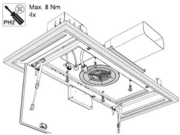
text_image
PH2 Max. 8 Nm 4x14
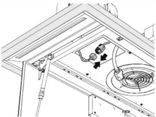
natural_image
Technical line drawing of a ceiling-mounted electrical enclosure with internal components and wiring (no text or symbols)Installation
15
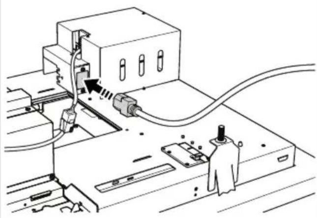
natural_image
Technical line drawing of a mechanical assembly with no visible text or symbols16
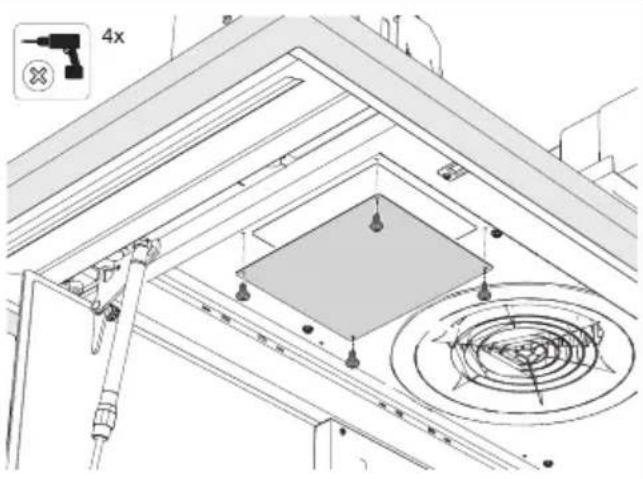
text_image
4x17
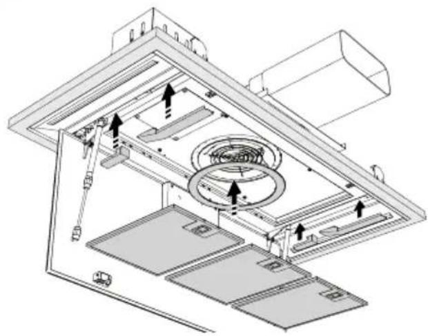
natural_image
Technical diagram of an air duct system with internal components and directional arrows (no text or labels)18

natural_image
Technical line drawing of a mechanical assembly with internal components and a curved arrow indicating motion (no text or symbols)19
text_image
Technical diagram showing a device mounted on a panel with labeled components C and W, including directional arrows and a magnified inset of the device.Installationflexibledescanaux
1
text_image
Front2
text_image
PH2 4x3
text_image
Technical diagram of an industrial machine with labeled components and directional arrows indicating flow or movement.4
natural_image
Technical line drawing of a mechanical assembly with internal components and directional arrows indicating motion (no text or symbols)5
text_image
PH 2 4x6
natural_image
Technical line drawing of a mechanical assembly with a rotating component and mounting bracket (no text or symbols)Installation
7
text_image
Technical diagram showing a mechanical assembly with labeled components and directional arrows indicating flow or movement.8
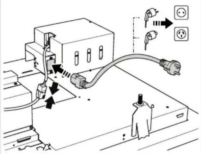
text_image
Diagram showing electrical connection with plug, socket, and power outlet, annotated with Chinese text and symbols9
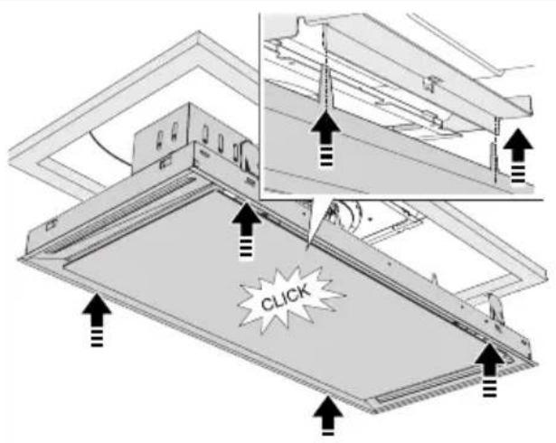
text_image
CLICK10
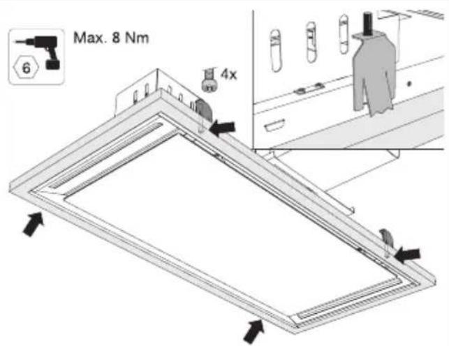
text_image
Max. 8 Nm 6 4x11

natural_image
Diagram of a rectangular panel with internal curved arrows indicating rotation or movement, mounted on a top frame (no text or symbols present)12
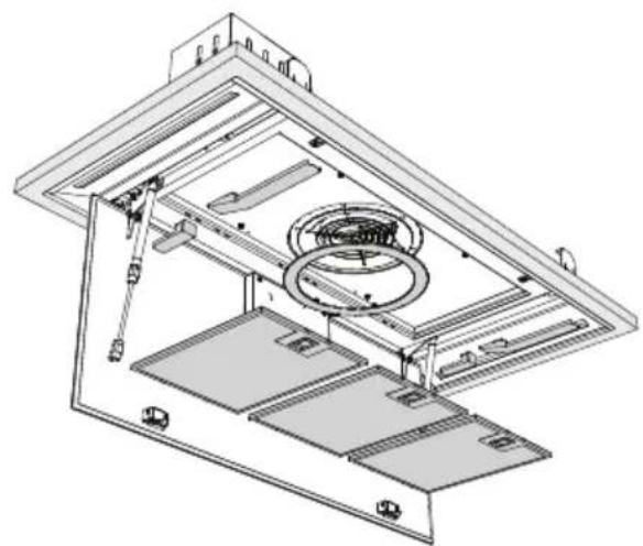
natural_image
Technical line drawing of an open industrial or mechanical device with internal components and mounting brackets (no text or symbols)13
natural_image
Technical line drawing of a mechanical assembly with a curved arrow indicating rotation or force (no text or symbols present)14
text_image
Diagram illustrating a device with labeled components and directional arrows, including a control panel and a circular indicator labels C and W.text_image
Warning symbol for a trash bin with crossed lines indicating no waste or discharge, and a black rectangle below.natural_image
Exterior view of a modern office building (no signage)GEBRAUCHSANWEISUNG
Abzugshaube
DE
CU902554TMM
CU122554TMM
CU122754TMM
text_image
- = ≡ ≡ Wi-Fitext_image
Diagram showing a menu bar with icons for menu, menu icon, and three horizontal lines with '三' symbols, alongside Wi-Fi icons.natural_image
Two white circular icons with dashed outlines on a black background, no text or symbols present.text_image
Diagram showing directional symbols including circles, arrows, and labeled points C and W on a black background
text_image
Diagram showing a grid icon with minus sign and Wi-Fi symbol, likely representing a basic wireless signal or data display.natural_image
Two circular icons on a dark background, one with a clock-like symbol and the other with a refresh icon (no text or labels)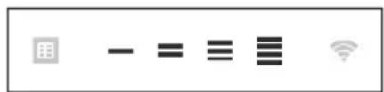
text_image
- = ≡ ≡ Wi-Finatural_image
Black background with white directional arrows and a central circular symbol (no text or labels)WLAN/ConnectLife-App
text_image
User interface toolbar with icons for grid, minus sign, equals sign, equals sign, and Wi-Fi signaltext_image
Screenshot of a software toolbar with icons for chart, menu, equals sign, menu bar, Wi-Fi, and radio buttontext_image
Screenshot of a software toolbar with icons for grid, minus sign, equals sign, equals sign, Wi-Fi symbol, and wireless signal.text_image
Diagram showing a menu bar with icons for data, equality,equiv, and Wi-Fi symbolstext_image
Row of five icons: grid, minus sign, equals sign, menu bar, and Wi-Fi symboltext_image
Screenshot of a software toolbar with icons for menu, keyboard, menu bar, list, and Wi-Fi symboltext_image
Diagram showing a menu with icons for data, equality, equals sign, and Wi-Fi signaltext_image
Screenshot of a software toolbar with icons for grid, minus sign, equals sign, three vertical bars, and Wi-Fi symboltext_image
Screenshot of a software toolbar with icons for data, menu, equals sign, three horizontal lines, and Wi-Fi symboltext_image
Screenshot of a software toolbar with icons for data, menu, equals sign, three horizontal lines, and Wi-Fi symboltext_image
User interface toolbar with icons for grid, minus sign, equals sign, equals sign, and Wi-Fi signalWLANeinschalten:
text_image
User interface toolbar with icons for grid, minus sign, equals sign, equals sign, and Wi-Fi signaltext_image
Screenshot of a software toolbar with icons for menu, zoom, and Wi-Fi settingstext_image
User interface toolbar with icons for grid, minus sign, equals sign, equals sign, and Wi-Fi signaltext_image
Screenshot of a software toolbar with icons for menu, keyboard, equals sign, menu bar, Wi-Fi symbol, and standard iconsnatural_image
Simple line drawing of a rectangular frame with a curved cutout and two arrows indicating direction (no text or symbols)natural_image
Illustration of a hand holding a tablet device with arrows indicating movement or force (no text or symbols)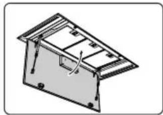
natural_image
Isometric line drawing of a mechanical housing or enclosure with internal components and mounting holes (no text or symbols)Reinigen
natural_image
Three technical illustrations: shopping cart, rolled-up cable, and plastic waste bin (no text or symbols)Festkanalinstallation
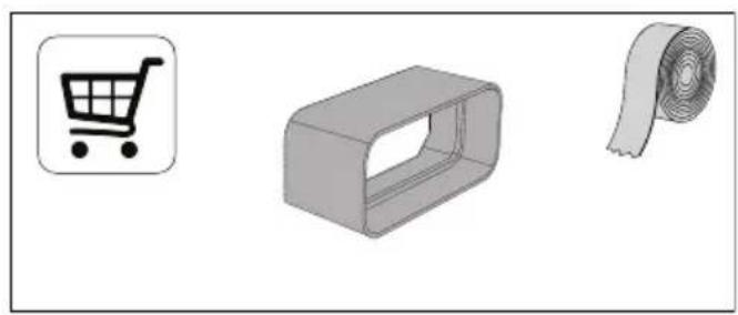
natural_image
Three gray 3D-rendered icons: a shopping cart, a rectangular box with a slot, and a rolled-up sheet of paper (no text or symbols)Geräteabmessungen
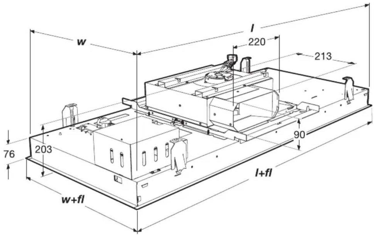
text_image
w l 220 213 76 203 90 l+fl w+fl| w+fll+flWLiter | ||||
| 504864480840CU9055T | ||||
| 50411644801140CU125. | ||||
| 72412247001200CU127. |
Einbau
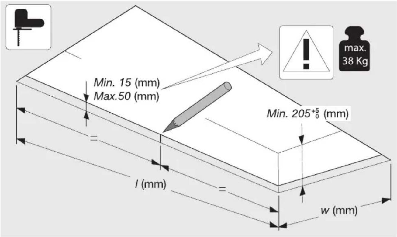
text_image
Min. 15 (mm) Max.50 (mm) = l (mm) = w (mm) Min. 205+5₀ (mm) max. 38 Kg| I | W | ||
| CU9055TMM | 847_± 2 | ± 2 | 21487 |
| CU1255TMM | 1147_± 2 | ± 2 | 27487 |
| CU12754TMM | 1207_± 2 | ± 2 | 38707 |
Festkanalinstallation
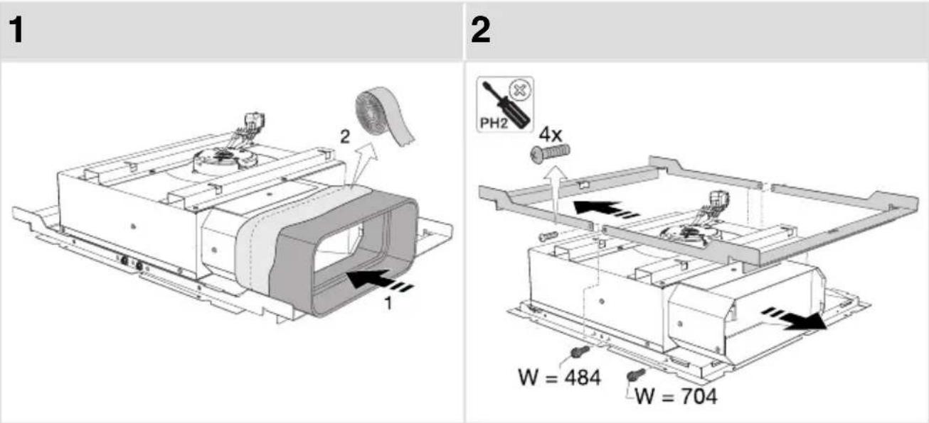
text_image
1 2 PH2 4x W = 484 W = 704Installation
3
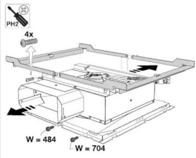
text_image
PH2 4x W = 484 W = 7044
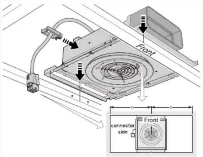
text_image
Front connector side Front5
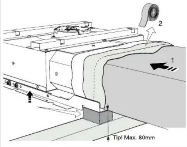
text_image
Tip! Max. 80mm6
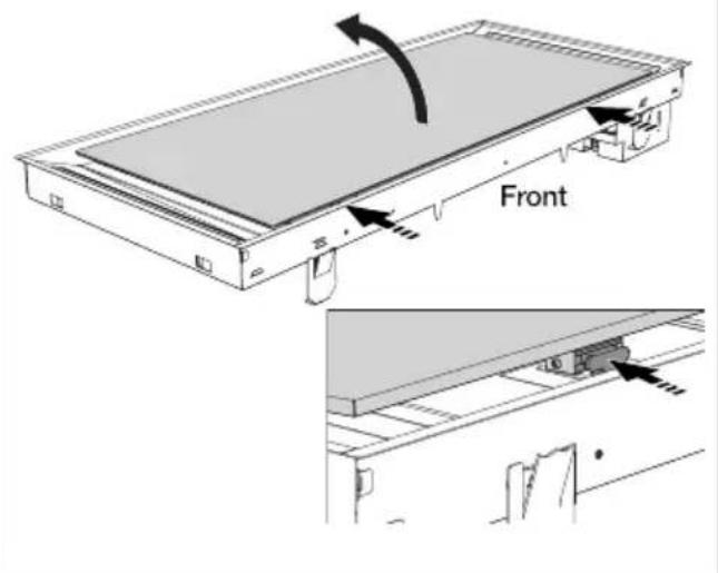
text_image
Front7
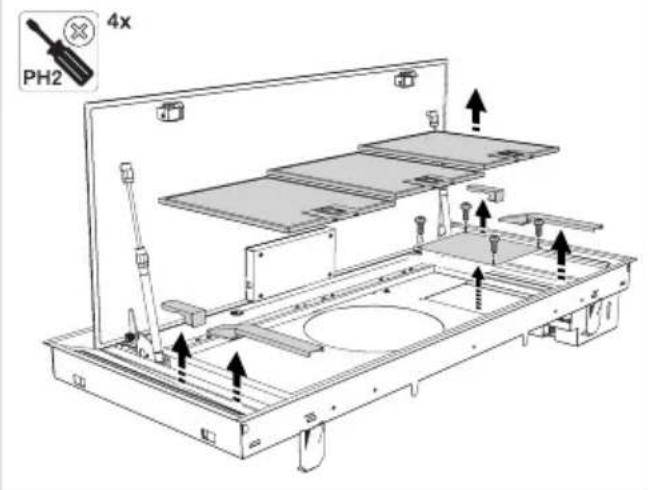
text_image
4X PH28
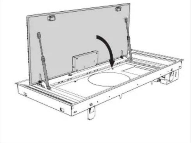
natural_image
Technical line drawing of a mechanical assembly with a central circular component and directional arrow (no text or symbols)9
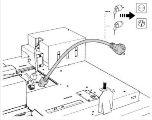
text_image
Technical diagram showing electrical connection setup with plug, socket, and power outlet connections10
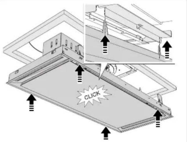
text_image
CLICK11
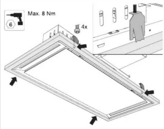
text_image
Max. 8 Nm 6 4x12
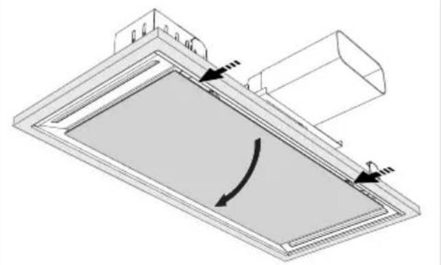
natural_image
Technical diagram of a mechanical component with directional arrows indicating motion or force (no text or symbols)13
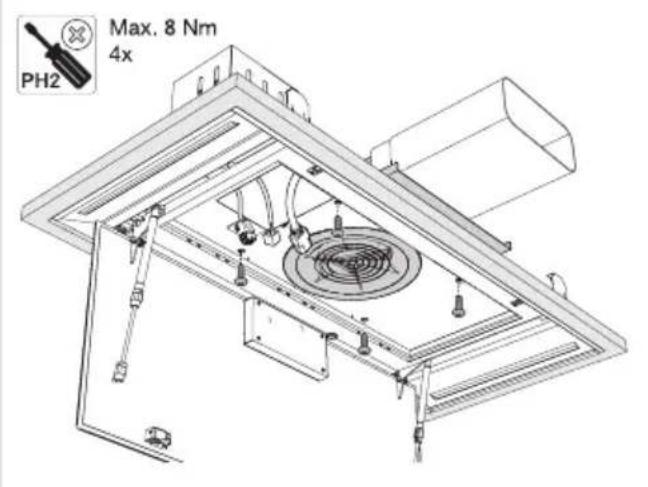
text_image
PH2 Max. 8 Nm 4x14
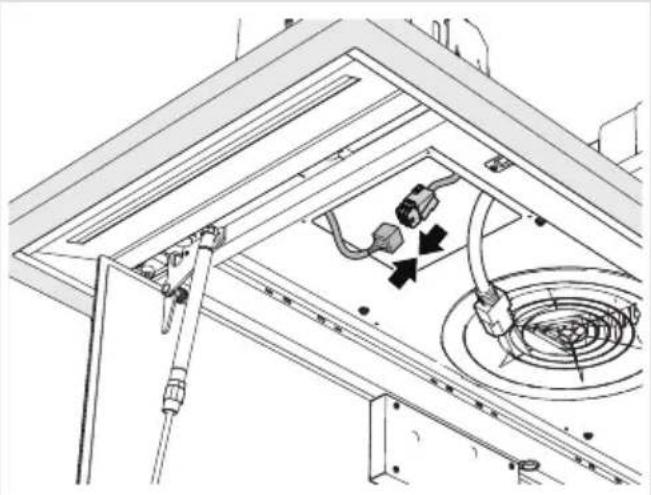
natural_image
Technical line drawing of a ceiling-mounted electrical enclosure with internal components and wiring (no text or symbols)Installation
15
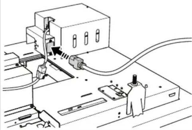
natural_image
Technical line drawing of a mechanical assembly with no visible text or symbols16
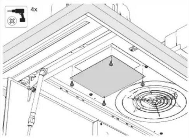
text_image
4x17
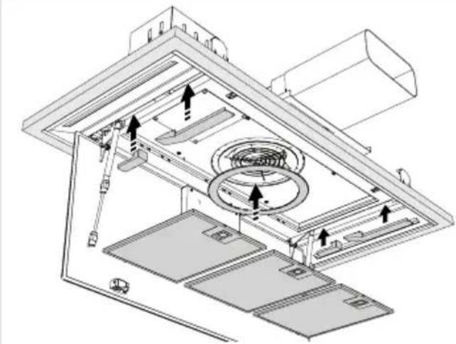
natural_image
Technical diagram of an air duct system with airflow indicators and component layout (no text or labels)18
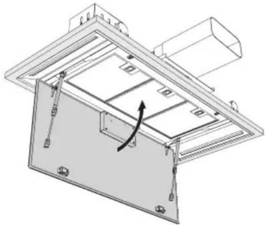
natural_image
Technical line drawing of a mechanical assembly with a curved arrow indicating rotation or movement (no text or symbols present)19
text_image
Technical diagram showing a device mounted on a panel with labeled components C, W, and directional arrows indicating motion or signal flow.FlexibleKanalinstallation
Installation
7
text_image
Technical diagram showing a mechanical assembly with labeled components and directional arrows indicating flow or movement.8
text_image
Diagram showing electrical connection with plug, socket, and power outlet components labeled in English9
text_image
CLICK10
text_image
Max. 8 Nm 6 4x11
natural_image
Diagram of a rectangular panel with internal curved arrows indicating rotation or movement (no text or symbols)12
natural_image
Technical line drawing of a mechanical assembly with internal components (no text or symbols)13
natural_image
Technical line drawing of a mechanical assembly with internal components and a curved arrow indicating motion (no text or symbols)14
text_image
Diagram showing a device with labeled components and directional arrows, including a control panel and indicator lights.text_image
Prohibition sign for a trash bin with crossed lines indicating no waste or dischargenatural_image
Symbol of a trash bin crossed with diagonal lines, representing waste sorting or disposal (no text or labels)natural_image
Exterior view of a modern office building (no signage)INSTRUCTIONSFORUSE
Cookerhood
EN
CU902554TMM
CU122554TMM
CU122754TMM
Contents
3Pictogramsused....
4Safety....
4.
7Yourcookerhood......
7Dearcustomer!......
8Descriptionhood......
8Descriptionuserinterface......
9Operation....
9Descriptionremotecontrol....
9Pairingtheremote....
10Switchingextractiononandoff......
10Switchontheboostsetting......
10Switchingonthetimer......
11Switchingonrecirculationmode......
11Switchingoffrecirculationmode......
11CleanAirfunction....
12Switchingthelightonandoff......
12Charts for energy unification took pre with the.... hoods......
12
13Wi-Fi-cor
13Wi-Fi/Con
18Maintena
18Cleaning.
20Filterindic
20Lighting..
21Batteryoft
22Technica
22EUProduc
23EUProduc
23Compliant
24Installatio
24......
26Preparatic
27Appliance
28Built-in....
35Environn
35
35Disposalc
36Yournote
Making the connection between cookerhood and hob....
Thefollowingsymbolsareusedthroughoutthemanual,andtheyhavethefollowingmeanings:

INFORMATION!
Information, advice, tip, or recommendation

WARNING!
Warning-general danger

ELECTRICSHOCK!
Warning-dangerofelectricshock

HOTSURFACE!
Warning-dangerofhotsurface

DANGEROFFIRE!
Warning-dangeroffire
It is important that you carefully read the instructions.
WARNING!
READCAREFULLYANDKEEPITFORFUTUREREFERENCE!
Safeuse
- This appliance is only designed for household use.
- CAUTION: Accessible parts may become hot when used with cooking appliances.
- This appliance can be used by children aged from 8 years and above and persons with reduced physical, sensory or mental capabilities or lack of experience and knowledge if they have been given supervision or instruction concerning use of the appliance in asafeway and understand the hazards involved.
- Donotallowchildrentoplaywiththeappliance.
- Donotallowchildrentocleanormaintaintheapplianceunless supervised.
•Alwaysprovideadequateventilation! - Thereshallbeadequateventilationoftheroomwhentherange hoodisusedatthesametimeasappliancesburninggasorother fuels.
- Whentherangehood and appliance supply supplied with energy other than electricity aresimultaneously in operation, then negative pressure in the room must not exceed 4Pa (4×10 ^-5 bar).
- Localregulationsconcerningthedischargeofairhavetobe fulfilled.
- Neveruseapressurecleanerorsteamcleanertocleanthe appliance.
ELECTRICSHOCK!
Avoidtheriskofelectricshock;makesuretheapplianceis switchedoffbeforecleaningtheappliance.
- Onlyusetheapplianceinsidethehome.
- Donotusethecookerhoodifthegreasefilterhasnotbeenfitted properly!
- Donotleanagainstthecookerhood.
- Neverusethecookerhoodasaworkingsurfaceunlesssthisis indicatedexplicitly.
- Grease and oil are inflammable when overheated. Remain in the cooking area when preparing meals.
- Topreventhotfatfromcatchingfire,youshouldonlydeep-fry undercontinuoussupervision.
- Thecookerhoodshouldbecleanedregularlybothontheoutside aswellastheinside(atleast1xpermonth).Insufficientcleaning oradelayinthereplacementoffilterscancauseafirehazard.
- Cleanthefiltersontime.
- Thegreasefilterscanbecomehotduringuse. Aftercookingwait at least 30 minutes before cleaning.
- Pleasenote! Intensiveusecanleadtocondensationonthe cookerhood. Condensationissimpletoremovewithadrycloth.
- Followtheinstructionsinthemanualforcleaningorreplacingthe greasefiltersand/orcarbonfilters!

DANGEROFFIRE!
Thereisariskoffireiftheinstructionsforcleaningorreplacing greasefiltersand/orcarbonfiltersarenotfollowed.
Throughgreasedepositsinthemetalgreasefilter.Neverwork withopenflameundertheappliance(eg.flambéing).Alwaysuse theappliancewiththemetalgreasefilter.Cleanthegreasefilter regularly.
Throughoverheatedfatoroil. Neverextinguishafirewithwater; alwaysuseafireblanket, lidorplate.
- The appliance may have sharpedges; please be careful during cleaning.
Safety
- ThelightemittedbyLEDlightsisverydazzlingandcandamage theeyes.DonotlookdirectlyintotheswitchedonLEDlightsfor longerthan100seconds.
- Whenwashinggreasefiltersinthedishwasheritisrecommended touseashort,non-intensiveprogramme.Checkthegreasefilter afterwashinginthedishwasherforwear(loosematerial).Wear canoccurasaresultoffrequentwashing.Ifloosematerialis visible,replacethefiltersinordertopreventthisloosematerial fromendingupinthefoodthatiscooked.
- Donotusetheapplianceintemperaturesbelow5°C.
Dearcustomer!
Pleasereadtheoperatinginstructionsbeforeuse. Theyincludegeneraltips, informationaboutthe settingsandadjustmentsyoucanmake,andthebestwaytotakecareofyourappliance.
TIP!
You can find them most recent version of the instructions for use on our website.
Enjoy your cooking!
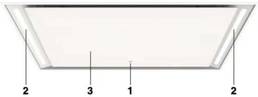
Descriptionhood
1.Userinterface
2.LEDbar
3. Edgeextraction panel
4. Greasefilter
5.Latch
text_image
2 3 1 2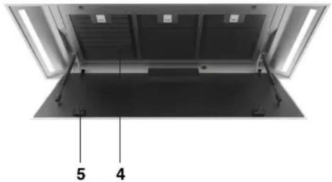
text_image
5 4Descriptionuserinterface
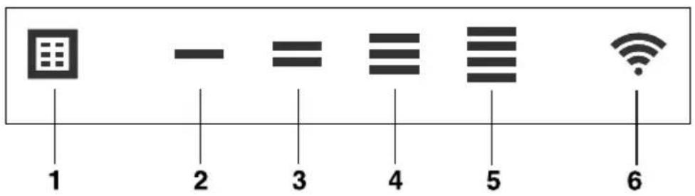
text_image
1 2 3 4 5 61.Filterresetbutton, signals when filters require cleaning
2. Speedlevel1 indicator
3.Speedlevel2indicator
4.Speedlevel3indicator
5.Speedlevel4/boostindicator
6.Wi-Fikey
Descriptionremotecontrol
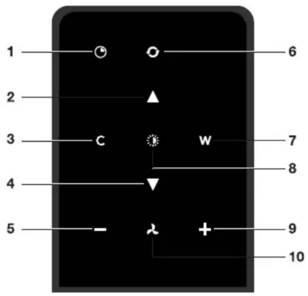
text_image
1 2 3 4 5 6 7 8 9 10- Timerfunction
- Increase light intensity
- Colderlighttemperature
- Decreaselightintensity
- Decreaseairextractioncapacity
6.CleanAirfunction - Warmerlighttemperature
8.Switchon/offlighting - Increaseairextractioncapacity
10.Fanon/off
Pairingtheremote
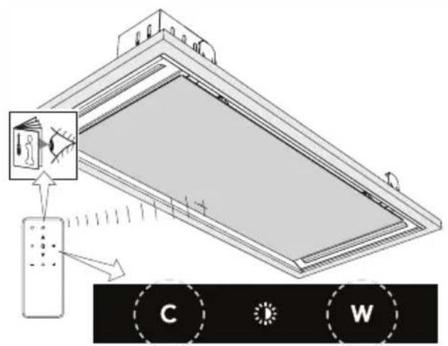
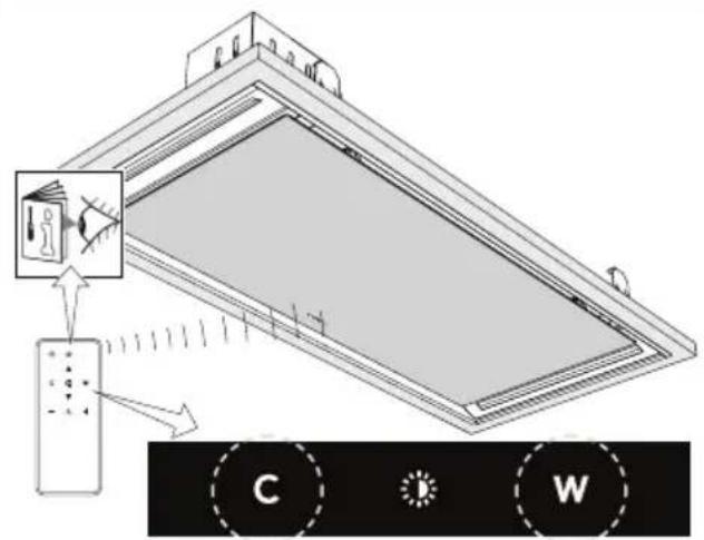
This remote control must be repaired to the cooker hood before first use.
- Start up the appliance (power on). The hood will start in 'pairing mode' for 5 minutes.
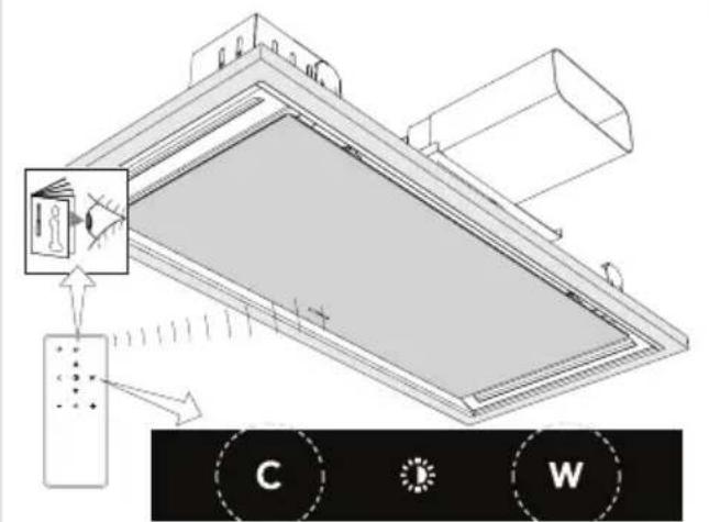
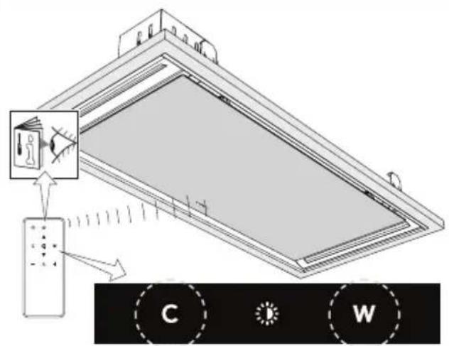
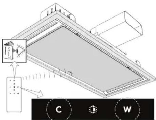
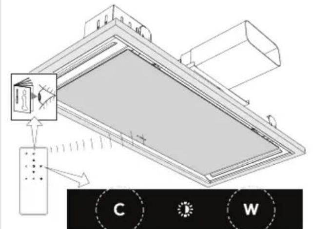
- Activate the 'Remote pairing mode' by holding 'c' and 'w' for 3 sec.

text_image
C W- During pairing all the indicators on the hood and remotewill blink. All indicators will turn off when the connection is established.
If the connection is not established, repeat the entire repairing process.
NOTE!
Remotecontrolwillgointostandbyafter30seconds. Theremotewillwakeupwhenitispicked upordetectsmovement.
Switchingextractiononandoff
- Pressandholdthe'Fan'keyontheremotefor1second.

text_image
- ⚡ +
text_image
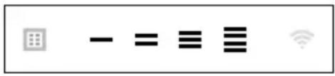
- = ≡ ≡Thecookerhoodwillswitchonatthelowestsetting.
- Press the '+' key again for a higher fan setting. Press and hold the '+' key for 1 second to select the highest setting (boost).
- Pressthe'-'keytoselectalowersetting.
The extraction setting is indicated by the speed level indicator on the hood.
- To switch off the cooker hood, press and hold the 'Fan' key for 1 second.
NOTE!
Lighting and motor key must be pressed for at least 1 second. This is to prevent the functions from being accidentally switched on or off.
Switchontheboostsetting
- Pressandholdthe'+'buttonforatleast1second.

text_image
- × (+)
text_image
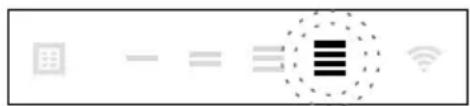
Diagram showing a grid connection with minus sign, equals sign, and Wi-Fi symbol, likely representing a basic arithmetic or data processing interface.Theboostsettingisswitchedonfor10minutes. Thespeedlevel4indicatorwillflashduringthis period. Theoriginalextractionsettingwillbereactivatedafterthisperiod.
- Pressandreleasethe'-'keytoswitchchofftheboostsetting.
NOTE!
If the boost setting has been selected, the timer function cannot be activated.
Switchingonthetimer
- Pressthetimerkey.

natural_image
Two white circular icons with dashed outlines on a black background, no text or symbols present.Thetimerindicatorwillstarttoblink.
Thecookerhoodwillswitchoffautomaticallyafter10minutes.
- Switchoffthetimerfunctionbypassingarandombutton(excepttheoneforlighting).
Switchingonrecirculationmode
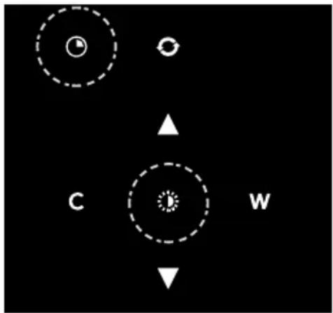
Whenthelightandfanareoff, simultaneouslyholdthetimerkeyandthelightkeyuntilthefilter indicatorflashes3times.
Thecarbonfilterindicatorisactivated.
text_image
Diagram with labeled geometric shapes and directional arrows, including circles and triangles
text_image
Diagram showing a grid icon with minus sign and Wi-Fi signal, likely representing a basic wireless communication interface.Switchingoffrecirculationmode
Whenthelightandfanareoff, simultaneouslyholdthetimerkeyandthelightkeyuntilthefilter indicatorlightsupfor3secondsandthenturnsoff.
TIP!
Ondelivery, this cooker hoodissetforexhaustairtotheoutside. The hoodcanalsobesetto recirculationuse (the airisblownbackintotheroomafterfiltrationthroughgreasefiltersanda combi-filter).
WithanRMSkit(recirculationmodificationset), the air will first be cleaned by the grease filters, and then odours will be filtered by the combi-filter. The cleanedair is recirculated back into the kitchen.
CleanAirfunction
TheCleanAirfunctionallowsyoutofreshentheairinyourkitchenforamaximumof24hoursat level1.
- Switchoffthecookerhood.
- Pressandholdthe 'CleanAir' key for approximately 3 seconds.

natural_image
Two circular icons with a dashed circle, no text or symbols present
text_image
Image displaying a row of icons including a grid, minus sign, equals sign, equals sign, three vertical lines, and a Wi-Fi symbol.Thecookerhoodwillswitchonautomaticallyfor10minuteseveryhouratthelowestspeed setting.Duringextraction,theindicatorlightsshowafast-runninglight.Whenthehoodswitchesoffafter10minutes,theindicatorlightsshowaslowrunninglightuntilthehoodswitchesonagainafter50minutes.
- Switch off the Clean Air function by pressing the timer, clean air, '-' or '+' keys (any key other thanthelightkey).
Switchingthelightonandoff
- Pressandholdthelightkeyfor1second.
Thelightswitchesonatmaximumstrength.
- Press and hold the 'increase light' or 'decrease light' key to set the lighting intensity.
- Toturnoffthelight, pressandholdthelightkey for 1 second.
NOTE!
Lighting and motor key must be pressed for at least 1 second. This is to prevent the functions from being accidentally switched on or off.
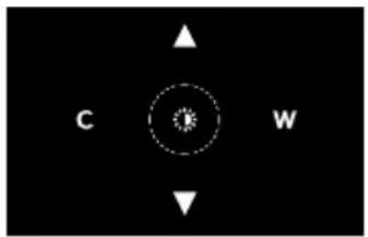
Changing the colour lighting temperature
natural_image
Black background with white directional arrows and a central circular symbol (no text or labels)You can adjust the lighting temperature.
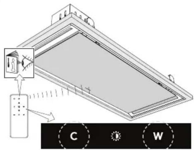
- Pressandholdthelightkeyfor1second. Thelightswitchesonatmaximumstrength.
- Press the 'C' key to make the light 'colder' or press the 'W' key to makethelight'warmer'.
Making the connection between cooker hood and hob
Tooperatethecookerhoodwiththehob,youmustmakeaconnectionbetweenthehobandthe hood.
Tomaketheconnection, the Connection setup mode of the cooker hood and the hob must be activated.
Seealsothemanualforthehob.Checkourwebsiteforthefullrangeofhobsthatcanbeconnected toyourcookerhood.
- The hood and lights must be switched off.
- Touchandholdsimultaneouslythe-(minus:keyandthe+(plus:keyfor3seconds.Allthe indicatorswillblinksimultaneouslyforamaximumof3minutes.
- On your hob, activatethepairingmodeintheusermenu(seethehobmanual). The connection to the hob is established.
- If the connection is successful, the cookerhood will return to standby.
NOTE!
When manually operating the hood in connection mode, the pairing will belostand must be paired again.
Wi-Fi/ConnectLife-app
The appliance is fitted with a Wi-Fi module that allows the appliance to connect to a mobile device such as a smartphone or tablet. It offers a monitor the appliance status via a mobile device.
NOTE!
Themonitoringfunctionviamobiledeviceshallnotbeusedtoreplacethepersonalsupervision ofthecookingprocessdirectlyontheappliance.
Requirements:
- To use the Wi-Fi connectivity of the cooking hob, the range of your Wi-Fi router must extend to the hob. The cooking hob on by supports 2.4GHz networks. If, during the connection setup, your homenetwork is not shown, check their outlet settings for 2.4GHz, that then network is no hidden and the signal is strong enough.
- Additionally, amobiledevicewithaninstalledConnectLife-appandaregistereduseraccount isrequired(seechapter'ConnectLife-app').

ConnectLife-app
The ConnectLife app is available on the Apple App Store and Google Play Store. After being paired withthehood,youcanusetheapptomonitorthestatusofthehood.
Gotowww.connectlife.io/getstartedtodownloadtheConnectLife-app,informationaboutthesystem, supportandavailablefeatures.Findadditionaloptionsunderwww.connectlife.io.
GettingstartedwiththeConnectLife-app
Get started with your ConnectLife-app in 3 easy steps. Please check as addition chapter "First steps to setup the Wi-Fi connectivity". More help under www.connectlife.io/getstarted.
1. Registration:
•InstalltheConnectLife-app.
- Starttheapp.
- Choose "Get Started" and follow the process.
- If you are already registered, use the "Sign In" option.
2.Addthehood:
- Intheapp:Goto"Appliances".
- Choose "Add Appliances" or touch the + (plus) key.
- Make sure Wi-Fi on the hood is turned ON, and the hood is in connection setup mode (see asaddition'FirststepstosetuptheWi-Ficonnectivity').
- FollowtheinstructionsoftheConnectLife-app.
3.Startcooking:
Congratulations, you can now start using ConnectLifetogether with your appliance.
FirststepstosetuptheWi-Ficonnectivity:
- Checkthe "Requirements" as described above.
- The hood and lights must be switched off.
- Touchandholdsimultaneouslythe-(minus:keyandthe+(plus:keyfor3seconds.Allthe indicatorsonthehoodandremotewillblink.
- PressanykeytoentertheWi-Ficonfigurationmenu.Speedlevels2,3and4indicatorslightup.

text_image
User interface toolbar with grid, minus sign, equals sign, equals sign, and Wi-Fi symbol- Touch the – (minus) key to turn on Wi-Fi. The Wi-Fi indicator will turn on and speed level 2 and 3 indicators will blink 3 times.

text_image
Screenshot of a software toolbar with icons for menu, chart, minus sign, menu bar, Wi-Fi symbol, and radio button- After 3 seconds it will return to the Wi-Fi-menu.

text_image
Row of icons including grid, minus sign, equals sign, equals sign, Wi-Fi symbol, and Wi-Fi icon- Touchthe+(plus)keytoentertheconnectionmenu.Confirmwiththetimerkeytostartthe 'Connectionmenu'.Speedlevel2indicatorandWi-Fiindicatorwillblinkduringtheconnection time.Thismodewillbedisabledautomaticallyafter5minutes.

text_image
Diagram showing five icons: a grid, minus sign, equals sign, Wi-Fi symbol, and a Wi-Fi icon, likely representing basic UI or data processing functions.8.StarttheConnectLife-appendfollowtheinstructionsintheapp.
9. If the Connect Life-app does not connect to the device, wait 10 minutes and repeat the steps described to leave the Wi-Fi menutouch and hold the light key for 3 seconds.

INFORMATION!
TroubleshootquicklybyturningtheWi-Fimoduleoffandonagain.Youcanfindmorehelpinthe "Wi-Fitroubleshooting"section.
DependingontheWi-Fistate,thereare1to3optionsavailableinthemenu:
•TheConnectionSetupMode
•ThePairingMode
- Remotecontrolmode
If more than 1 option is available then set the + (plus) and - (minus) keystotoggle between the options.
ConnectionSetupMode
- The appliance must be connected to the Cloud for the application to monitor and control the appliance remotely.
- Speedlevel2indicatorandWi-Fiindicatorwilllightup.

text_image
Screenshot of a software toolbar with icons for grid, minus sign, equals sign, menu bar, Wi-Fi symbol, and standard icons.- Touch the timer key to enable 'Connection Setup Mode'. Speed level 2 indicator will flash.
- Thismodewillbedisabledautomaticallyafter5minutes.
- FollowtheinstructionsoftheConnectLife-app.
PairingMode
When the process was successful and you want to pair another user, you can use the "Pairing mode" of the Wi-Fi menu and the "Pairing" or "Discovery" option of the ConnectLife-app. In the ConnectLife-app, selection 'AddAppliance' and follow the instructions.

text_image
Row of gray icons representing menu, keyboard, equals sign, menu bar, menu list, and Wi-Fi symbol- Touch the timer key to enable 'Pairing mode'. The speed level 3 indicator will flash.

text_image
Screenshot of a software toolbar with icons for window, menu, equals sign, menu bar, Wi-Fi symbol, and standard icons- Thismodewillbedisabledautomaticallyafter3minutes.
- On the ConnectLife-app, use the 'Pairing' or 'Discovery' option of the ConnectLife app to pair anotheruser.
Remotecontrolmodeswitchonandoff
Tobeabletochangefunctionsettingsremotely, theappliancemustbeswitchedonandthe ConnectLife-appmustbeenabled.Speedlevel4indicatorandWi-Fiindicatorwilllitstatic.

text_image
Screenshot of a software toolbar with icons for grid, minus sign, equals sign, equals sign, Wi-Fi symbol, and standard iconRemotecontrolmodeisonlyavailableiftheWi-Ficonnectivitysetuphasbeenperformed.Touch thetimerkeytoenable'Remotecontrol'.
- Speedlevel4indicatorisblinking:Remotecontrolisenabled.

text_image
Screenshot of a software toolbar with icons for menu, menu bar, equals sign, three horizontal lines, and Wi-Fi symbol- Speedlevel4indicatorlitstatic:Remotecontrolisdisabled.

text_image
Screenshot of a software toolbar with icons for grid, minus sign, equals sign, three horizontal lines, and Wi-Fi symbolToclosetheWi-Fimenu,touchandholdthelightkeyfor3seconds.Ifnokeyistouchedwithin10 minutes,theWi-Fimenuwillbeswitchedoffautomatically,thehoodwillbebackinstandbymode.
Wi-Fimenu
ToaccesstheWi-Fimenuthehoodmustbeonstandby(thehoodandlightsmustbeswitchedoff).
- Touch and hold simultaneously the – (minus) key and the + (plus) key for 3 seconds. All the indicatorsonthehoodandremotewillblink.
- Press any key to enter the Wi-Fi configuration menu. Speed levels 2, 3 and 4 indicators light up.

text_image
User interface toolbar with icons for grid, minus sign, equals sign, equals sign, Wi-Fi signal, and navigation barSwitchingonWi-Fi:
•Thehoodandlightsmustbeswitchedoff.
- Touch and hold simultaneously the – (minus) key and the + (plus) key for 3 seconds. All the indicatorsonthehoodandremotewillblink.
- Press any key to enter the Wi-Fi configuration menu. Speed levels 2, 3 and 4 indicators light up.

text_image
User interface toolbar with grid, minus sign, equals sign, equals sign, and Wi-Fi icons- Touch the – (minus) key to turn on Wi-Fi. speed level 2 and 3 indicators will blink 3 times. The Wi-Fiindicatorwillturnon. After 3 seconds it will return to the Wi-Fimenu.

text_image
Screenshot of a software toolbar with icons for chart, menu, equals sign, menu bar, Wi-Fi, and signal symbolsSwitchingoffWi-Fi:
•Thehoodandlightsmustbeswitchedoff.
- Touch and hold simultaneously the – (minus) key and the + (plus) key for 3 seconds. All the indicatorsonthehoodandremotewillblink.
- Press any key to enter the Wi-Fi configuration menu. Speed levels 2, 3 and 4 indicators light up.

text_image
Screenshot of a software toolbar with icons for grid, minus sign, equals sign, equals sign, Wi-Fi, and wireless signal.- Touch the – (minus) key to turn off Wi-Fi. speed level 2 and 3 indicators will lit static. The Wi-Fi indicatorwillturnoff.After3secondsitwillreturntotheWi-Fimenu.

text_image
Row of five icons representing basic computer, data, math, list, and Wi-Fi symbols- ToleavetheWi-Fimenutouchandholdthe'-(minus)keyfor3seconds.
DisplayingtheWi-Fistatus:
- Wi-Fimoduledisabled:Wi-Fiindicatorisoff.
- Configurationinprogress:Wi-Fiindicatorflashes.
- Connectedtohomenetworkrouter:Wi-Fiindicatorflashes.
- Connectedtohomenetworkrouterandcloud:Wi-Fiindicatorcontinuouslylit.
Wi-Fitroubleshooting
| SolutionPossiblecauseSymptom | ||
| Wi-Fiturnedoff.Wi-Fiiconnotsh | SwitchonWi-Fi(see'Switchingon Wi-Fi'). | |
| Homenetworkissues.Wi-Fisetup | Opheldhatyourhomenetworksignal isstrongandinternetconnectionis working. | |
| Homenetworkisnot displayedduringconnection setup. | Thehomenetworkisnoton 2.4GHz,thenetworkis hidden,orthesignalstrength istoowek. | Pleasecheckthenetworksettings.Ensurea2.4GHzandvisiblenetwork.Ifthesignalistoowek,trytomovethe networkrouterclosertotheappliance. |
| Applianceisshown disconnectedonthemobile app. | Wi-Fiisdisabledorhome networkissues. | EnsurethatWi-Fiisenabledandthe internetconnectioninyourhome networkisworking.Repeatthe connectionsetupifnecessary. |
| Differentcauses.OtherWi-Fipro | FilendisabletheWi-Fiandenableit again.Checkthattheinternet connectioninyourhomenetworkis working.Repeattheconnectionsetup ifnecessary.Furthertroubleshootingavailableon www.connectlife.ioorcontactthe servicedepartment. |
Cleaning
WARNING!
Important!For all maintenance, first, switch off themains power to the cooker hood by pulling the plug out of the socket or by turning off the home's masters switch. The hood needstobe cleaned regularly, both inside as well as outside (at least as often as the grease filter).
Donotuseabrasivecleaningproducts.Donotusealcohol!
If the instructions regarding cleaning the appliance or replacing the filters are not followed, this can cause a fire. These instructions must be followed! The manufacturer is not liable for damage to the hood or fired a damage resulting from incompetent maintenance or from non-adherence to the safety instruction above.
Cookerhood
Cleanthecookerhoodwithsoapywaterandasoftcloth.
Thenrinsewithcleanwater.Donotuseaggressivecleaningagentssuchascausticsoda.Thecooker hoodfinishstaysingoodconditionifitisbuffedperiodicallyfollowingtheapplicationofwax.
NOTE!
Stainlesssteelcookerhoods
Donotusescouringpadsorotherabrasivecleanersonstainlesssteelcookerhoods. Finishwith anon-abrasive, non-polishingagentandbuffthestainlesssteelinthedirectionofthegrain.
Metalgreasefilters
Metalgreasefiltersshouldbecleanedonceamonth(orwhenindicatedbythefiltercleaningindicator – if present on the model) using a neutral cleaning agent, either by hand or in the dishwasher on a short,low-temperatureprogram.Placethegreasefilterswiththeopeningsfacingdownwardsinthe dishwashersothewatercandrainoutofthefilter.Aluminiumgreasefiltersbecomedullasaresult ofdishwashercleaningagents.Thisisnormalanddoesnoteffecttheworking.
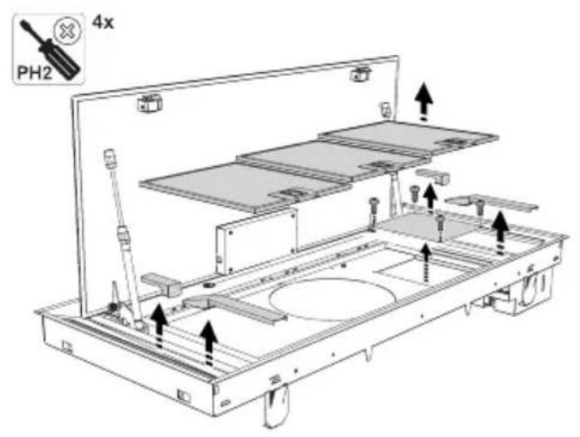
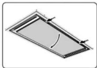
Removingcassettefilter
natural_image
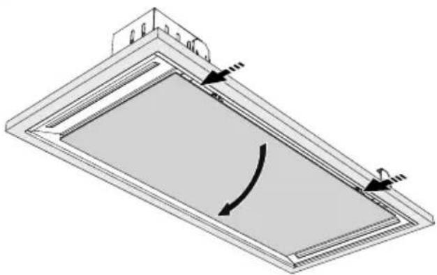
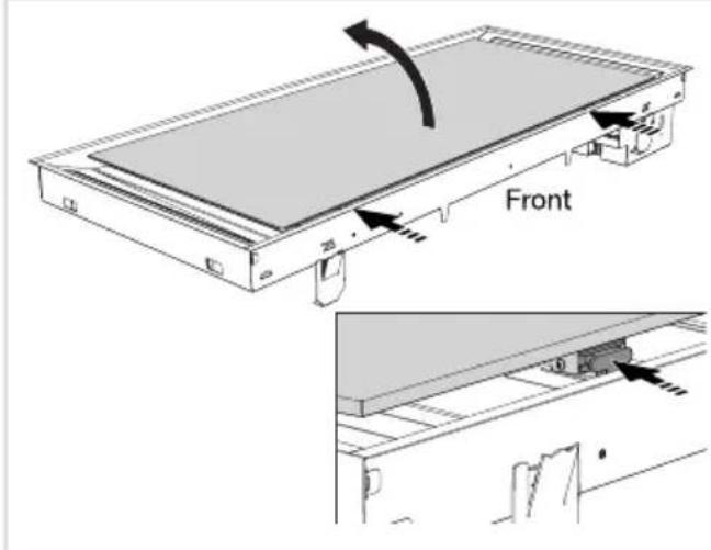
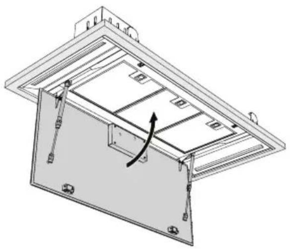
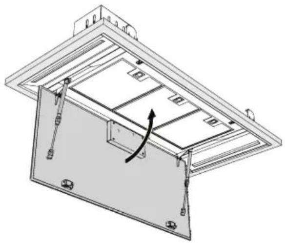
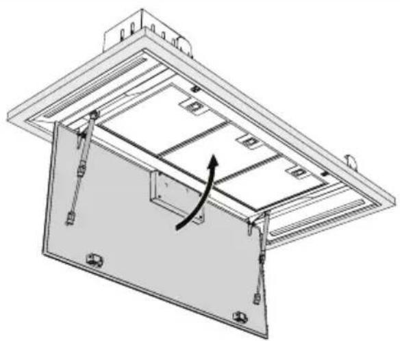
Diagram of a rectangular panel with a curved cutout and directional arrows, no text or symbols present.- Switchoffthemotorandlighting.
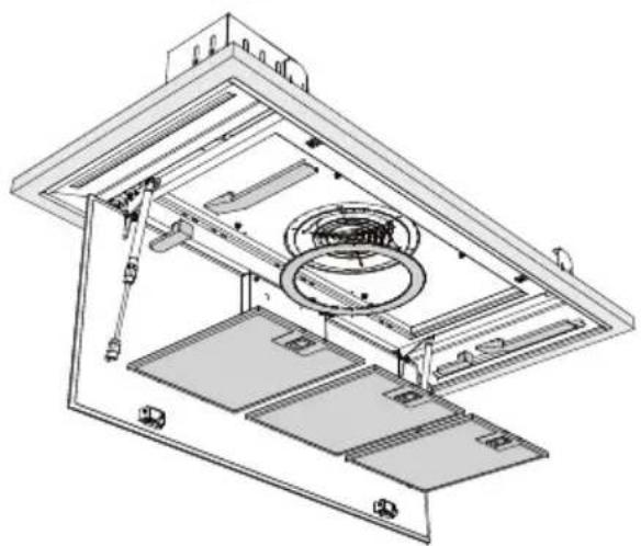
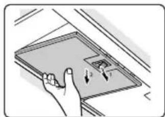
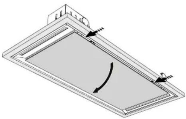
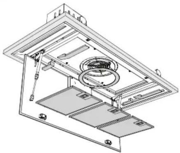
2.Pushinthelatchesandopenthepanel. - Openthefilter's accesslatch. Support the filter with your hand.
- Removethefilterfromthehood.
natural_image
Illustration of a hand holding a tablet device with arrows indicating motion (no text or symbols)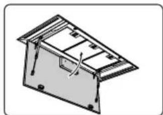
natural_image
Isometric line drawing of a mechanical housing or enclosure with internal components and mounting holes (no text or symbols)Cleaning
Thefilterscanbecleanedinthedishwasher.Allowthefilterstodrainwellbeforereplacing.
Thefilterscanalsobecleanedbyhand.
Cleanthefiltersinsoapywaterwithwashingupliquidandrinse.Allowthefilterstodrainwell.The undersideofthecookerhoodcanbecleanedwithamildcleaningagentandadampcloth.Dryoff withapapertowel.
Replacingcassettefilter
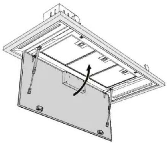
Thefiltersshouldbeplacedwiththelockingmechanismonthefront.Openthefilteraccesslatch. Thenotchesatthefrontofthefilterwillthenslotin.Holdtheaccesslatchinthispositionwhenplacing thefilters.
1.Slotthenotchesatthebackofthefilterinthespeciallydesignedopeningofthecookerhood.
2. Tiltthefilterupwards.
3. Releasethefilteraccesshatch. Thenotchesatthebackofthefilterwillextendoutwardsand slotintothespeciallydesignedopeningsofthecookerhood.
Thefilterisnowinpositionagain.
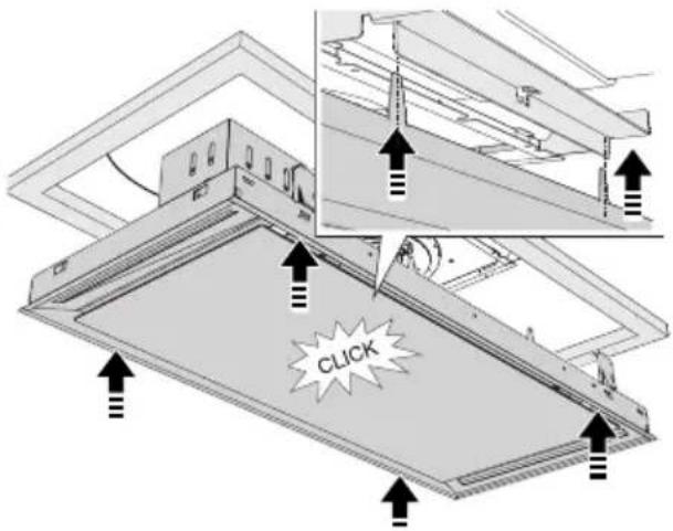
- Presstheglassplatefirmlyinthesealagain(youwillhearaclick).

WARNING!
Theglassplatecanberemovedforcleaning.Twopeoplearerequiredwhenremovingtheglass plate(duetoitsweight)!
Activecarbonfilters
Theregenerableactivecarbonfiltermustbewashedbyhandwithneutralcleaningproducts,orinthedishwasheratamaximumtemperatureof65°C(thewashingshouldbedonewithoutanyplates,dishes,cups,etc.inthemachine).Donotusewashingdetergent.
Removetheexcesswaterwithoutdamagingthefilter,removetheholderandletthefilterdryinthe ovenforatleast40minutesatamaximumtemperatureof70°C.
Tokeeptheregenerablecarbonfilterefficient, this actions should be repeated every 2 months or when indicated by the filter indicator. The filter must be replaced after non more than 3 years, or if it has been damaged.
CAUTION!
It is important that the grease filters and there are a reliable active carbon filter are thoroughly dry before repositioning.
Replacingthecarbonfilter
Toreplacethecarbonfilter,consultthemanualfortherecirculationkit.
Filterindication
Saturationofgreaseandcarbonfilters
The filters should be replaced or cleaned when the filter indicator is lit. See 'Maintenance' chapter.
Greasefilter
The filter indicator will light up after 30 operating hours.
- Thegreasefiltersshouldthenbecleaned.
- Reset the memory by pressing and holding the filter reset button until the filter indicator goes off.
Carbonfilter
The filter indicator will flash after 120 operating hours.
- Thecarbonfiltershouldthenbecleanedorreplaced.
- Reset the memory by pressing and holding the filter reset button until the filter indicator goes off.
Lighting
WARNING!
ThehoodisfittedwithLEDlights.Anauthorizedtechnicianmustreplacethese.Donotattempt toreplacetheLEDlightsyourself.
Batteryoftheremote
NOTE!
- Whenthebatteriesarereplacedthepairingconnectionwillremain.
- Replace the batteries in time, as the receiving distance will be shortened if the voltage of the batteryistoolow.
- Don't forget to remove the batteries if you don't use the remote for a long time.
- Don'tleavetheremotelyingupsidedownonaconductivesurface.
- Thewarrantydoesnotcoverthebatteries.
- The battery may drain more quickly in connection with the liticons.
- Batteryspecifications: TwoAAAbatteries.
EUProductSheet
Datadeterminedaccordingto:
StandardEN61591andCommissionRegulations(EU)no.65/2014and(EU)no.66/2014.
| CU122754TMMCU122554TI | |||
| ATAGATAGATAGTrademark | |||
| IC12AA-BCB01WC12AA-BC | |||
| [kWh/a]hood) | 39.038.538.0AnnualEnergyC | ||
| Energyefficiencyclass | A++ | A++ | A+ |
| hood)[%] | 38.737.937.7FluidDynamicEf | ||
| AAAFluidDynamicEfficiencyc | |||
| hood)[lux/W] | 66.572.593.2LightingEfficien | ||
| AAALightingEfficiencyclass | |||
| [%]hood) | 78.579.687.6GreaseFiltering | ||
| CCBGreaseFilteringEfficienc | |||
| speedinnormaluse[m 3/h] | 330/418303/414319/402Airflk | ||
| Air flow at intensive or boost setting [m3/h] | 710 | 716 | 724 |
| Airborne acoustical A-weighted sound poweremissionsatminimumand maximumspeedinnormaluse[dB(A)] | 52 / 58 | 53 / 59 | 53 / 59 |
| Airborne acoustical A-weighted sound poweremissionsatintensiveorboost setting[dB(A)] | 73 | 71 | 71 |
| Powerconsumptionoffmode(Po) | - | - | - |
| (Ps)[W] | 0.350.350.35Powerconsump |
EUProductFiche
| CU122754TMMCU122554TI | |||
| 0.60.60.6Timeincreasefactor | |||
| hood) | 37.236.636.5EnergyEfficiency | ||
| efficiencypoint(Q _BEP ) [m3/h] | 453455441Measuredairflow | ||
| efficiencypoint(P _BEP ) | 480474480Measuredairpres | ||
| efficiencypoint(W _BEP ) | 156158156Measuredelectric | ||
| (W_L) | 6.65.35.3Nominalpowerofthe | ||
| systemonthecookingsurface(E _middle ) [lux] | 439384494Averageilluminati |
Complianceinformation
| RFmoduleRadioequipmenttype | |
| 2402-2477MHz(16channels)Operatingfrequencyrange | |
| -5.2dBmEIRPaverage(calculated)Maximumoutputpower | |
| -7dBiMaximumantennagain |
| Wi-FimoduleRadioequipmenttype | |
| 2412-2472MHz(16channels)Operatingfrequencyrange | |
| 17.7dBmEIRPaverage(calculated)Maximumoutputpower | |
| Maximumantennagain | 2.7dBi |
Hereby, ATAGdeclaresthattheradioequipmenttypeCookerhoodisincompliancewithDirective 2014/53/EU.
Safetyregulations
WARNING!
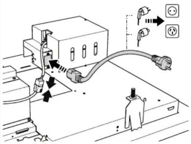
Thisapplianceshouldonlybeconnectedbyaregisteredinstaller.
- Always follow the installation instructions in the installation manual provided.
- Checktheappliancefortransportdamage.Donotconnecta damagedappliance.
- Faultypartsmayonlybereplacedbyoriginalparts. Themanufacturercanonlyguaranteethatoriginalpartsmeet safetyrequirements.
- If the supply cord is damaged, it must bere placed by the manufacturer, its service agent or similar qualified persons in order to avoid a hazard.
- AlwaysusetheoriginalSupplycordtoconnecttheappliance.
- Theelectrical connection must comply with national and local regulations.
- Thewallplugsocketandplugshouldalwaysbeaccessible.
- Ifastationaryapplianceisnotfittedwithasupplycordanda plug,orwithothermeansfordisconnectionfromthesupplymains havingacontactseparationinallpolesthatprovidefull disconnectionunderovervoltagecategorylllconditions,the meansfordisconnectionmustbeincorporatedinthefixedwiring inaccordancewiththewiringrules.Thisisalsoapplicablefor applianceswithasupplycordandplugwhentheplugisnot accessibleafterinstallingtheappliance.Usinganomnipolar switchwithacontactseparationofatleast3mmfittedinthefixed wiringwillfulfilthisrequirement.
- Theapplianceshouldnotbeconnectedtothemainsviaa multi-plugadapterorextensioncable,asthesafeuseofthe equipmentcannotbeguaranteed.
WARNING!
Neveropenthecasingoftheappliance.
- Disconnect the appliance from themain supply before starting any repair work.
- Weadviseyoutowearprotectivegloveswhenassemblingthe cookerhoodbecauseofthepossiblesharpedges.
- Thedistancebetweenthelowestpointofthecookerhoodand thesupportingsurfaceforthecookingvesselsgashobshould beatleast65cm.
- If the instruction of the gashobspecify a greater distance, this hastobetaken into account.
WARNING!
Failuretoinstallscrewsorfixingdevicesinaccordancewiththese instructionsmayresultinanelectricalhazard.
If the safety instructions and warnings are not followed, the manufacturer cannot be held responsible for any resulting damage.
If you decide to discontinue using the appliance because of a fault, were recommend you cutoff the cable after removing the plug from the plug socket. Take the appliance to your municipality's waste disposalsite.
Placetheapplianceinanenvironmentthatmeetsthefollowing conditions:
- Ambianttemperaturerange: +5....+40°C;
•Humidity:30....70%RH;
•Maximumaltitude:2000metersabovesealevel.
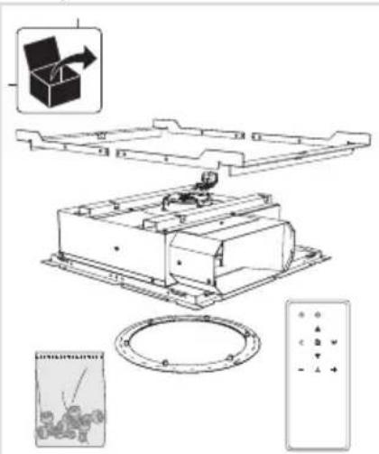
Preparationsforinstallation
text_image
Technical diagram of a mechanical assembly with labeled components and a 3D box icon showing directional arrow.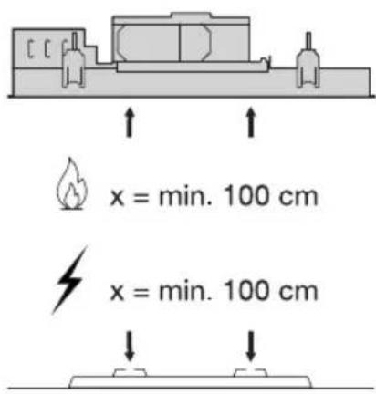
text_image
x = min. 100 cm x = min. 100 cm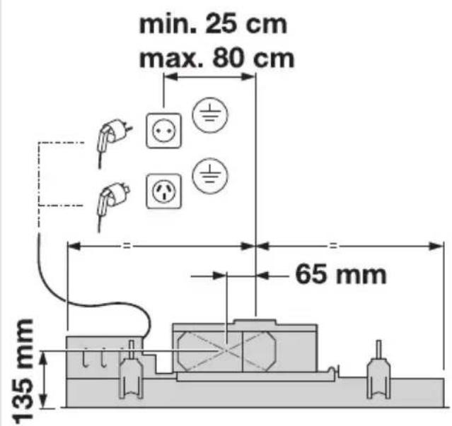
text_image
min. 25 cm max. 80 cm 65 mm 135 mmCAUTION!
Donotfittheappliancedirectlyontoplasterboard(orsimilarlightweightmaterials)inasuspended ceiling.
Installtheappliancewithafixingmaterialwhichissufficientlystableandhasbeenadjusted accordinglyforboththestructuralconditionsandtheweightoftheappliance.
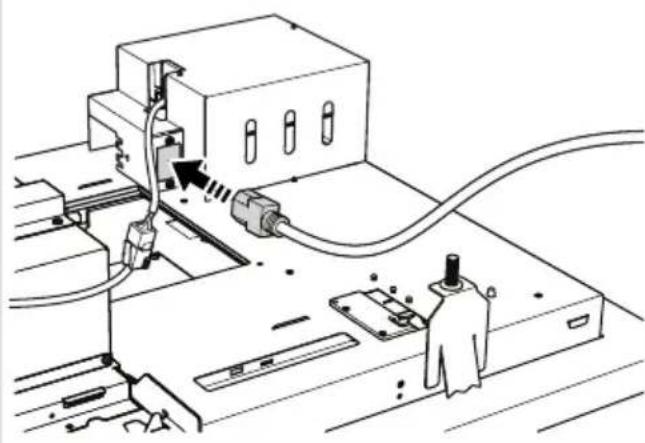
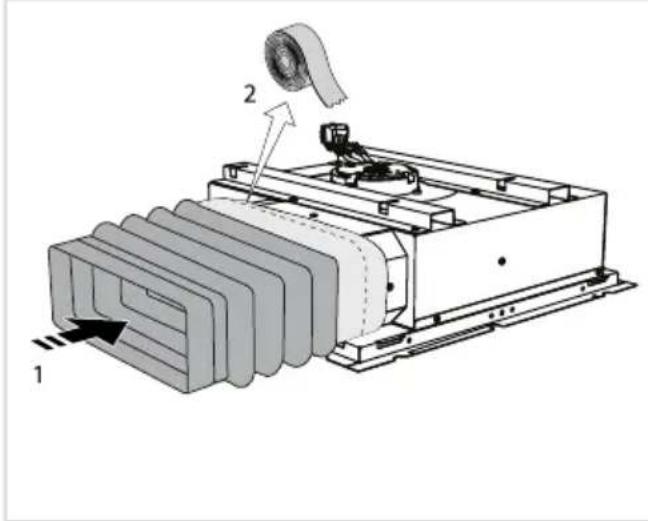
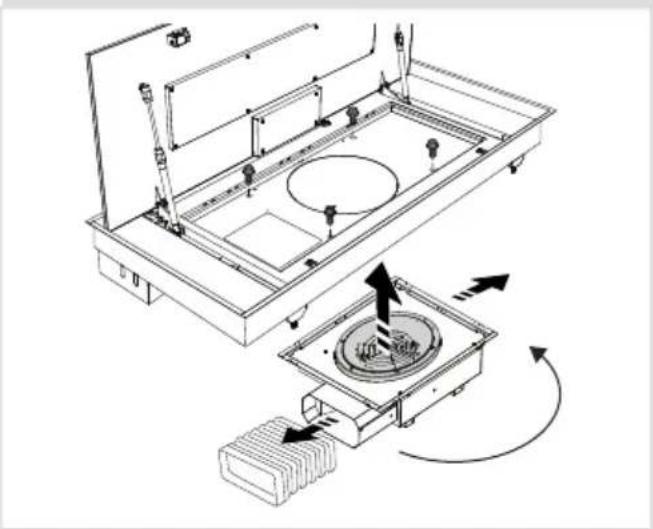
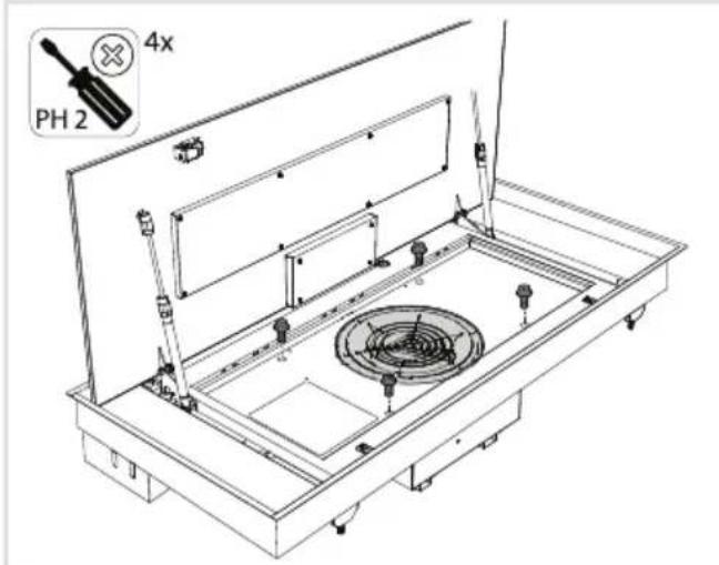
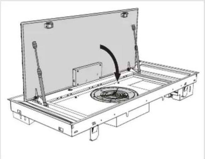
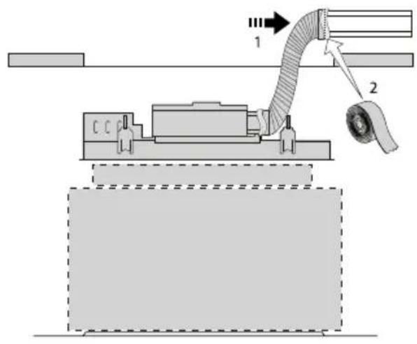
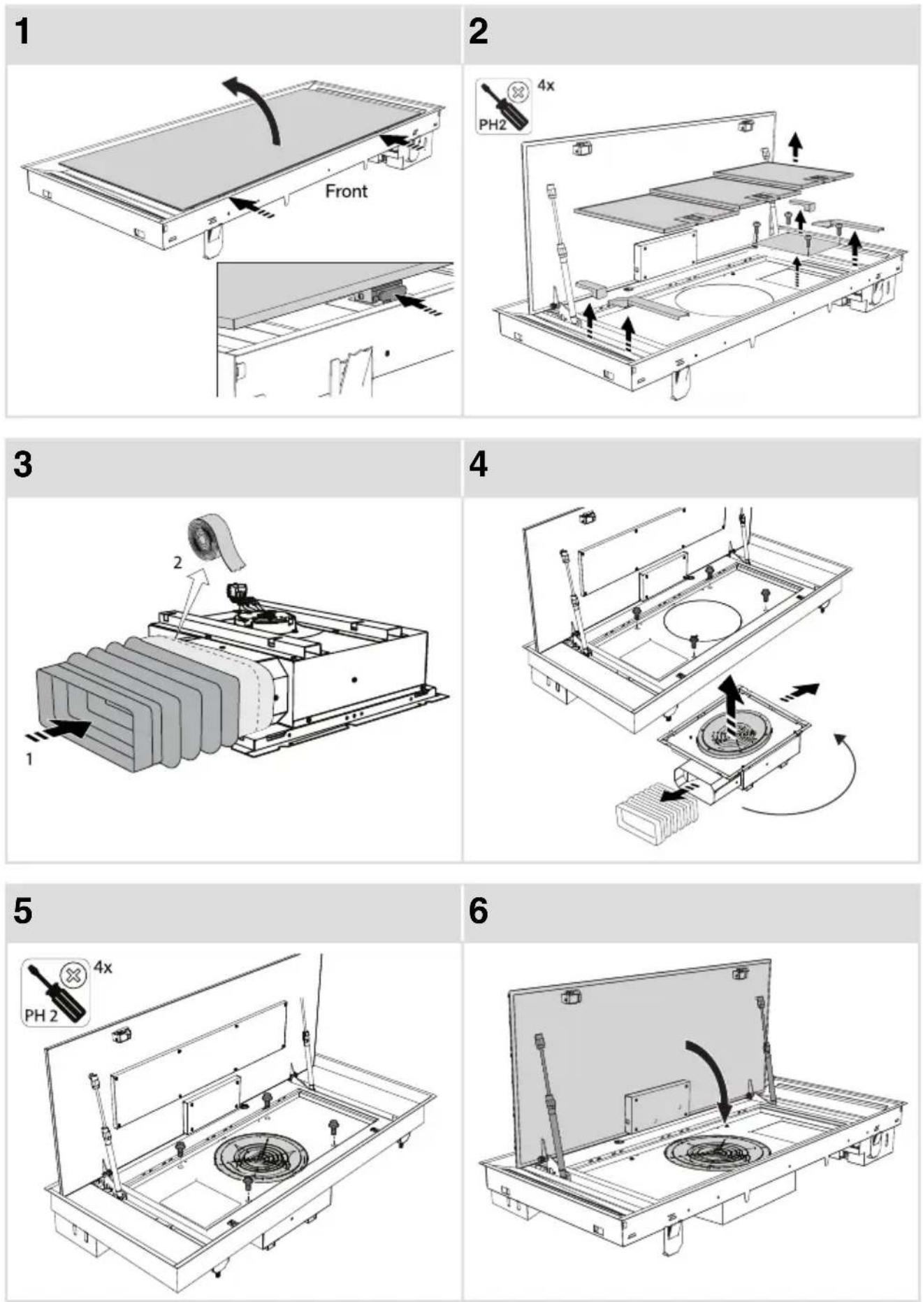
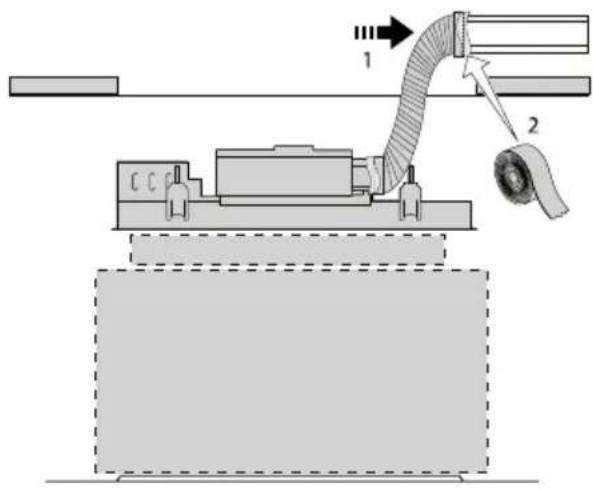
Flexiblechannelinstallation
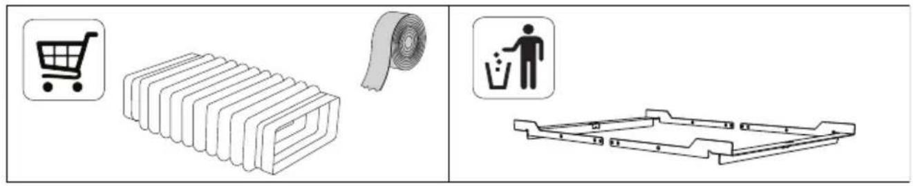
text_image
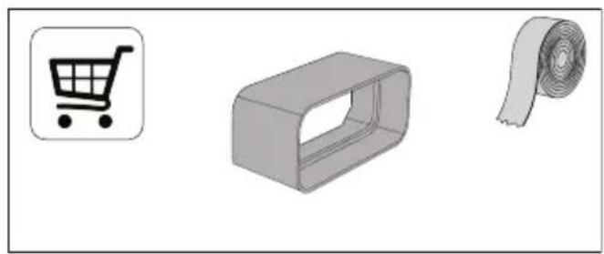
Diagram showing shopping cart, rolled paper, and trash bin with icons for each componentFixedchannelinstallation
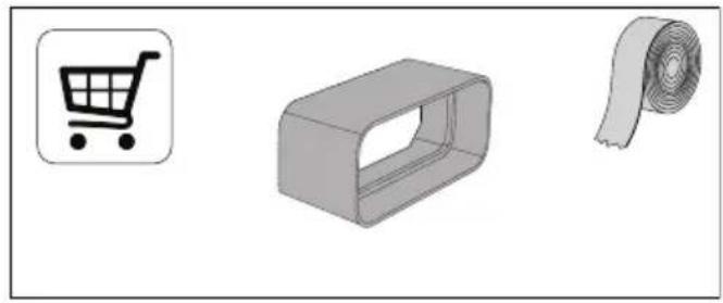
natural_image
Three gray 3D-rendered objects: a shopping cart icon, a rectangular box with a slot, and a roll of tape (no text or symbols)Appliancedimensions
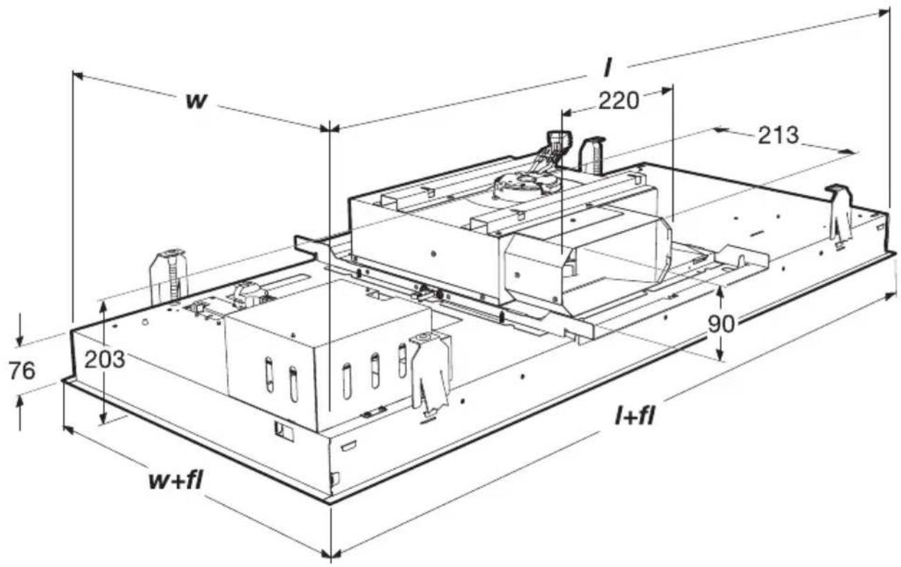
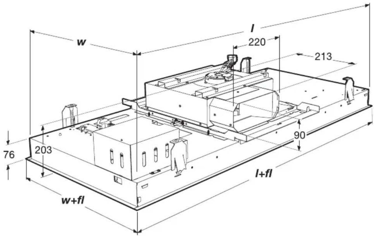
text_image
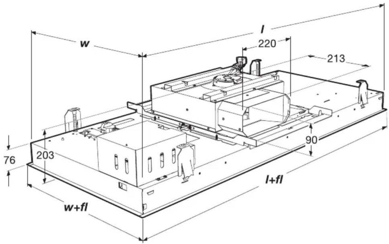
w l 220 213 76 203 90 l+fl w+fl| w+fll+flWliter | ||||
| 504864480840CU9055T | ||||
| 50411644801140CU125. | ||||
| 72412247001200CU127. |
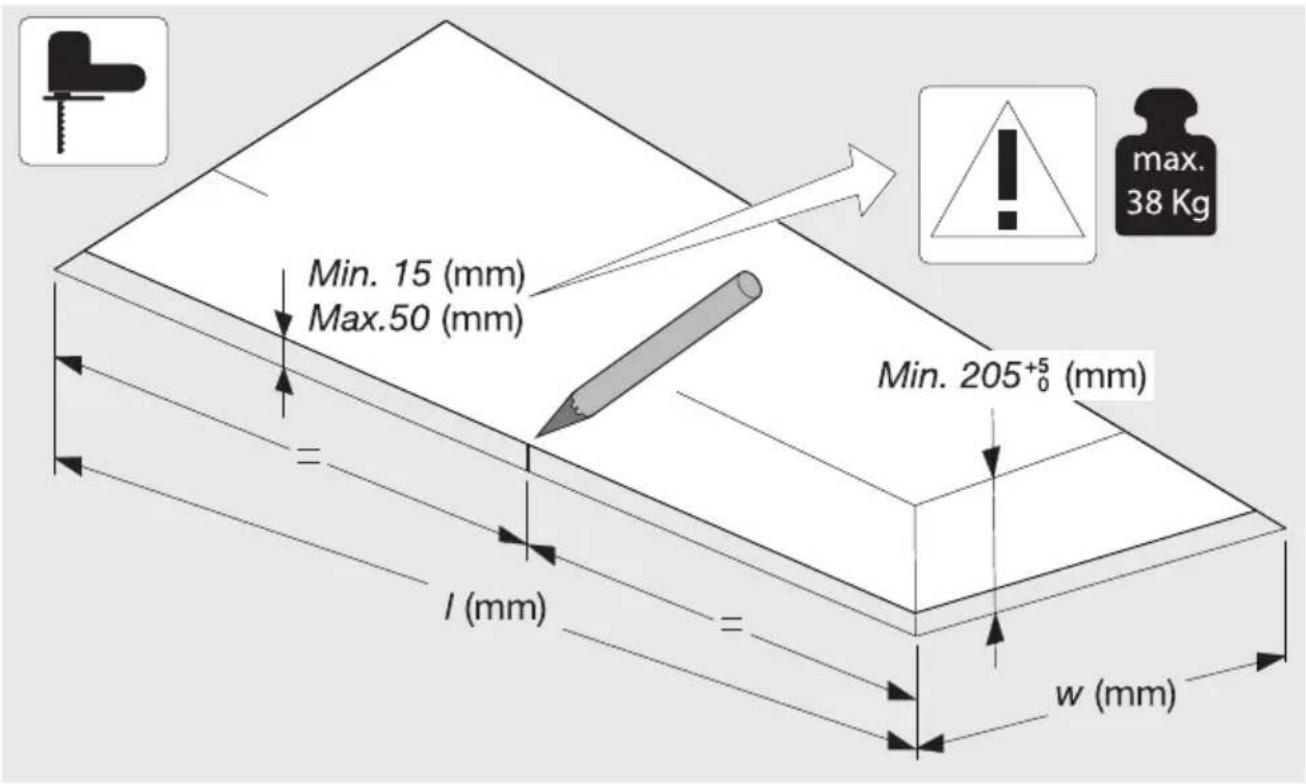
Built-in
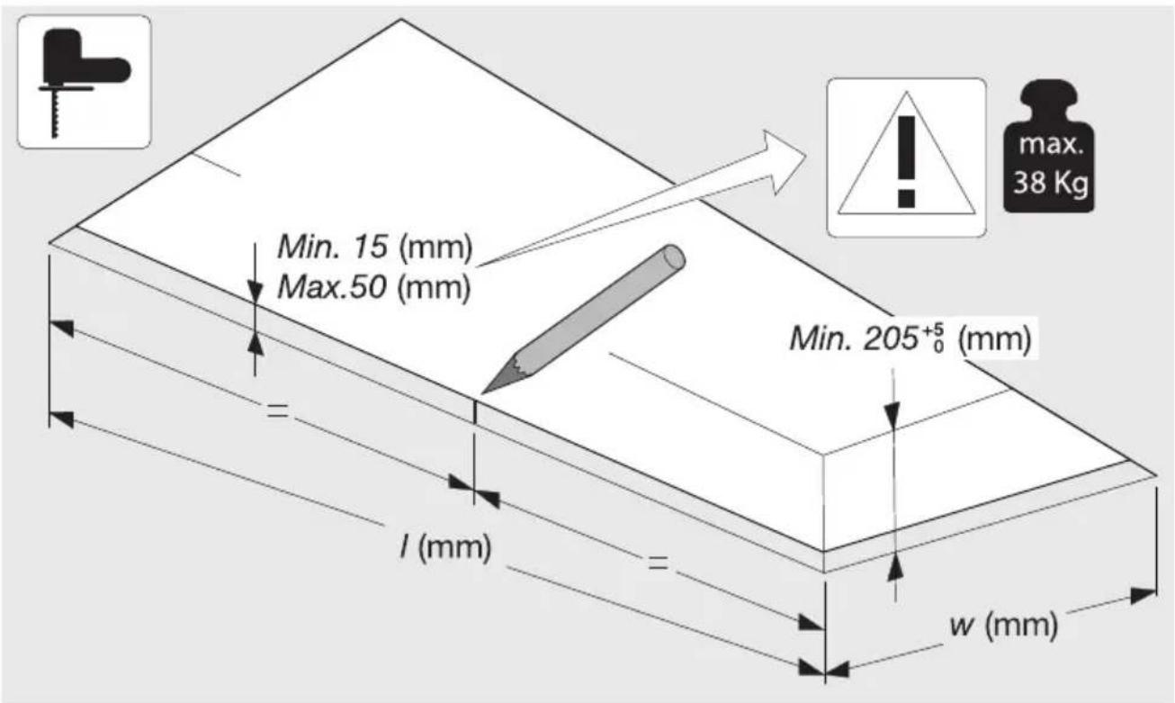
text_image
Min. 15 (mm) Max.50 (mm) = l (mm) = w (mm) Min. 205+5₀ (mm) max. 38 Kg| I | W | ||
| CU9055TMM | 847_± 2 | ± 2 | 21487 |
| CU1255TMM | 1147_± 2 | ± 2 | 27487 |
| CU12754TMM | 1207_± 2 | ± 2 | 38707 |
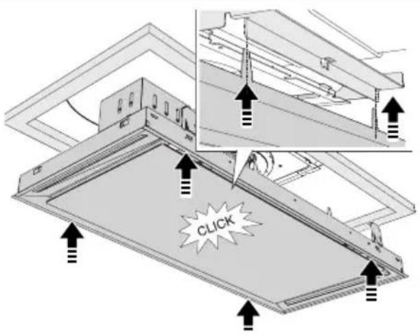
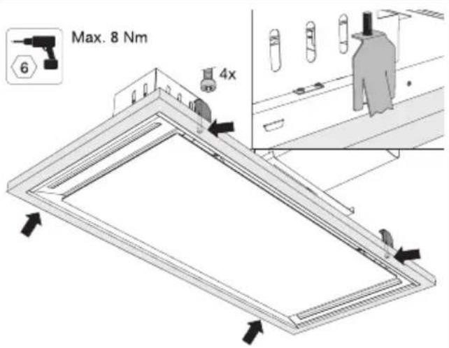
Fixedchannelinstallation
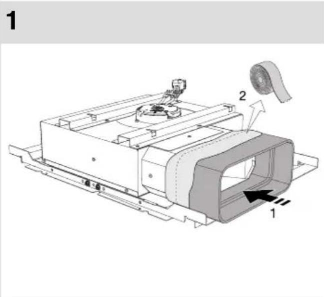
text_image
1 2 1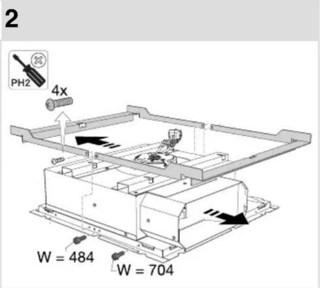
text_image
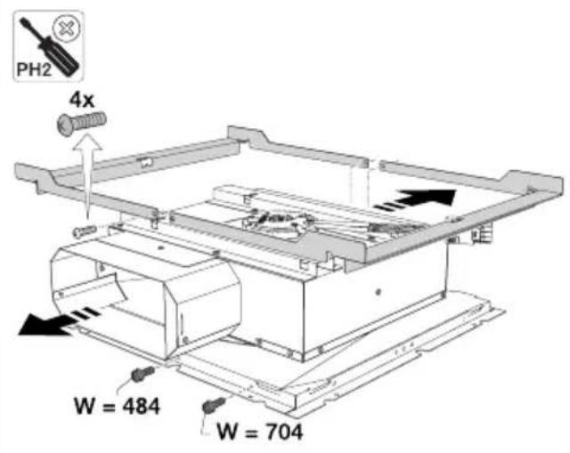
2 PH2 4x W = 484 W = 7043
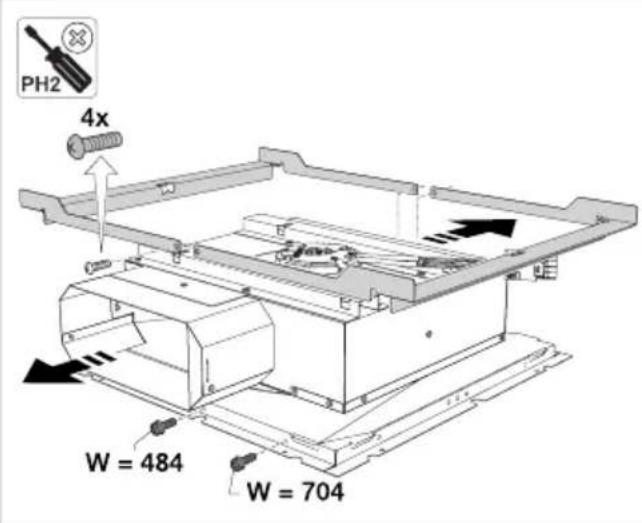
text_image
PH2 4x W = 484 W = 7044
text_image
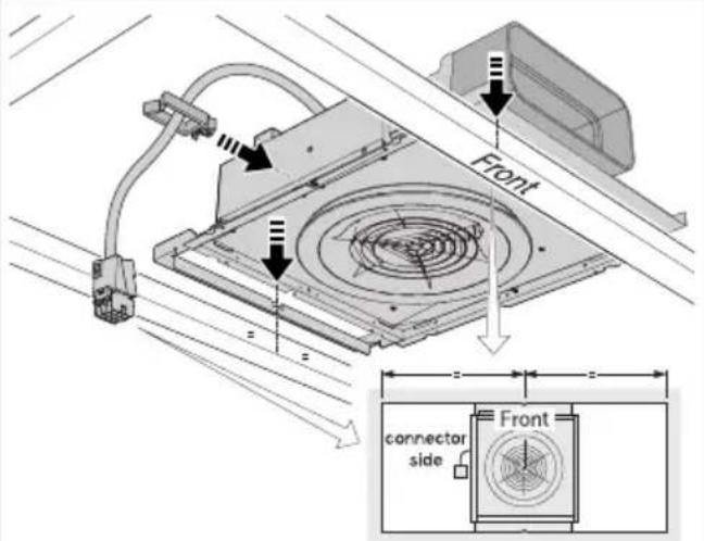
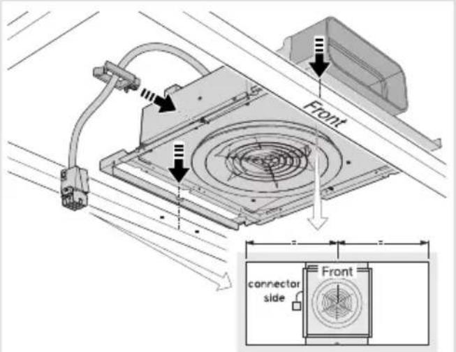
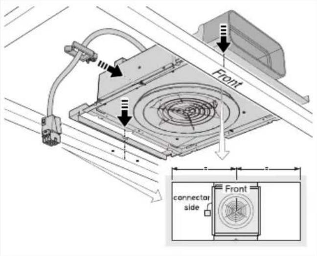
Front connector side Front5
text_image
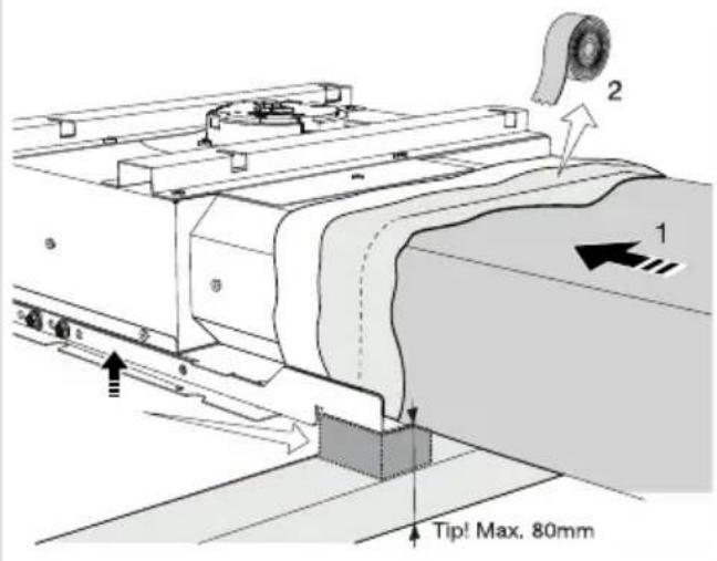
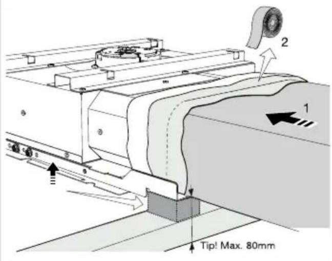
Tip! Max. 80mm6
text_image
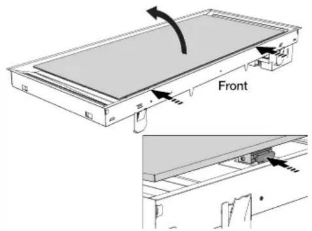
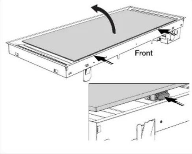
Front7
text_image
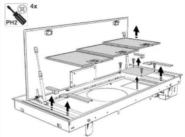
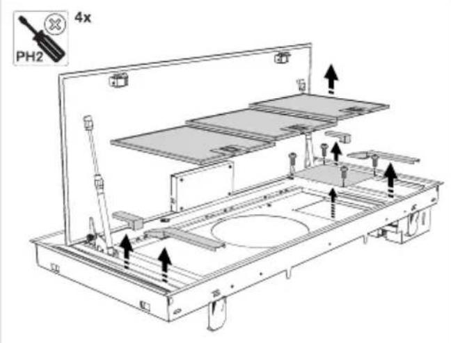
4x PH28
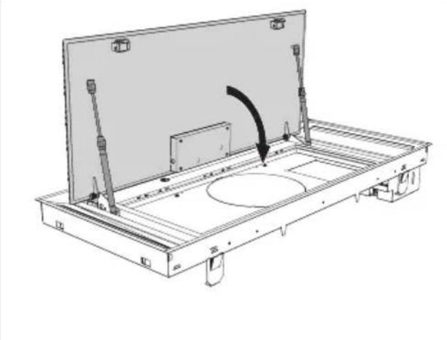
natural_image
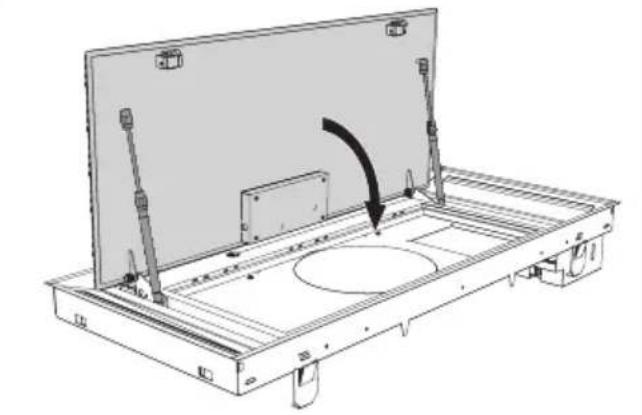
Technical line drawing of a mechanical assembly with a central circular component and directional arrow (no text or symbols)Installation
9
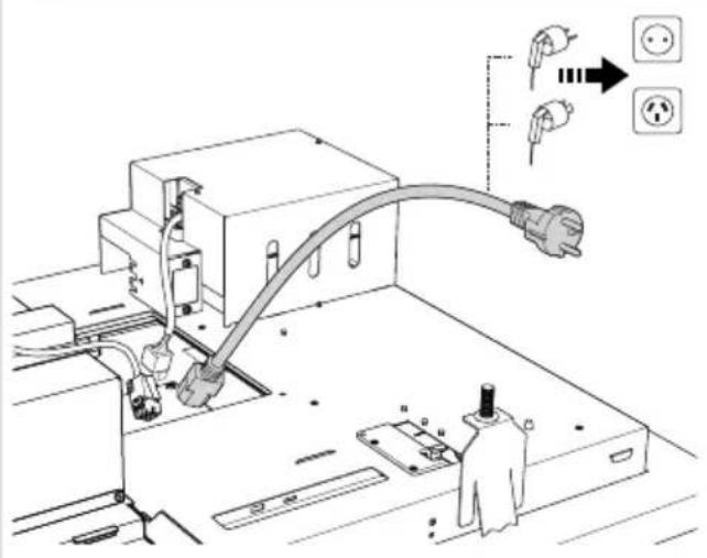
text_image
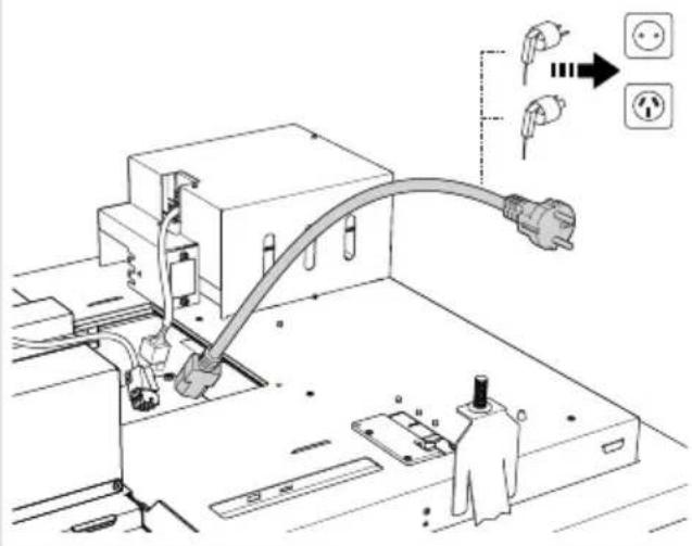
Technical diagram showing installation of an electrical outlet with plug, socket, and power outlet connections10
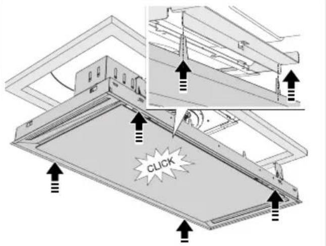
text_image
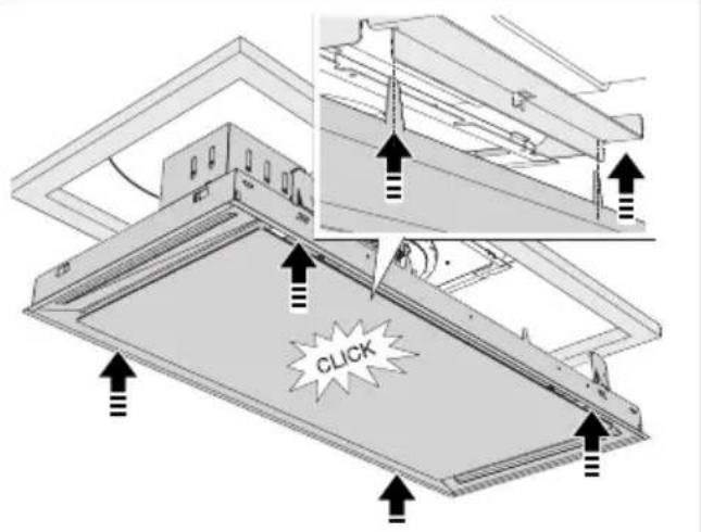
CLICK11
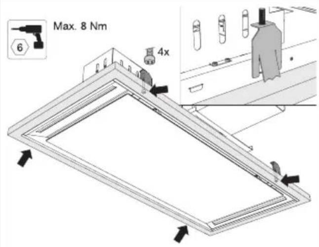
text_image
Max. 8 Nm 6 4x12
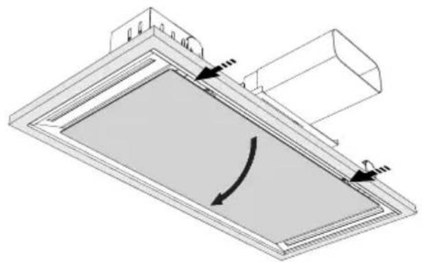
natural_image
Technical diagram of a mechanical component with directional arrows indicating motion or force (no text or symbols)13
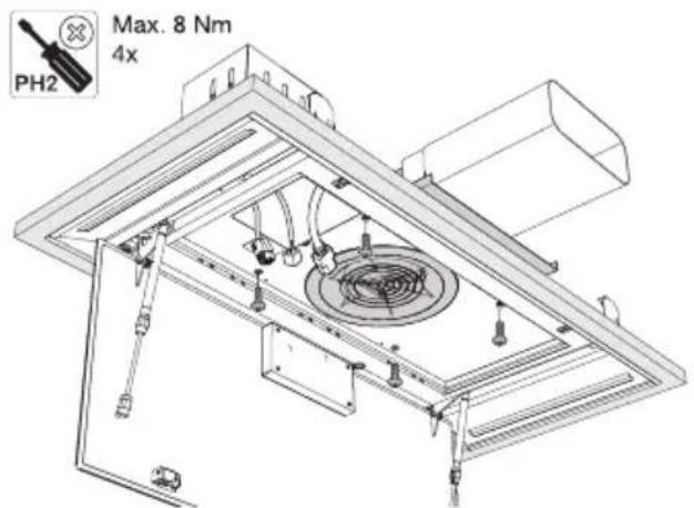
text_image
PH2 Max. 8 Nm 4x14
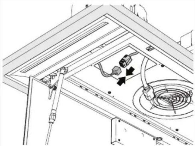
natural_image
Technical line drawing of a ceiling-mounted electrical enclosure with internal components and wiring (no text or symbols)15
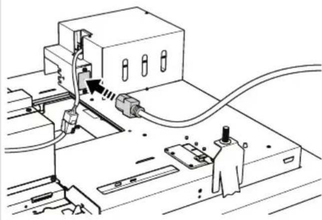
natural_image
Technical line drawing of a mechanical assembly with no visible text or symbols16
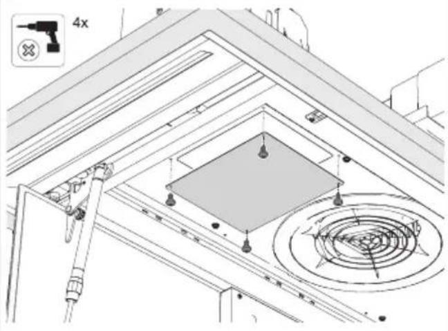
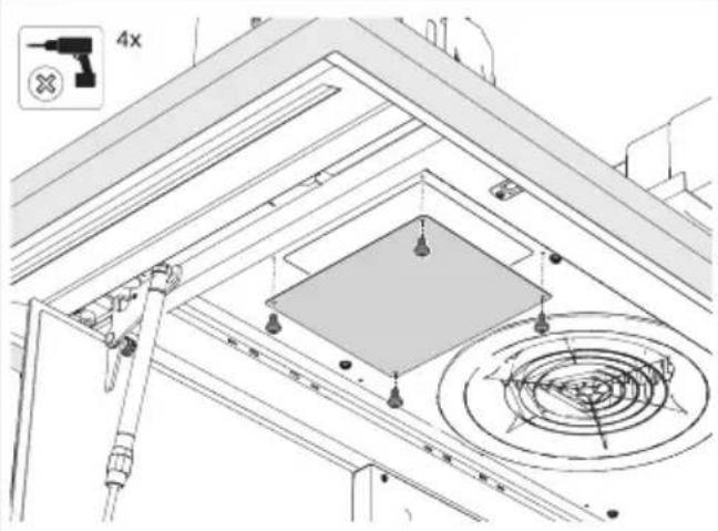
text_image
4x17
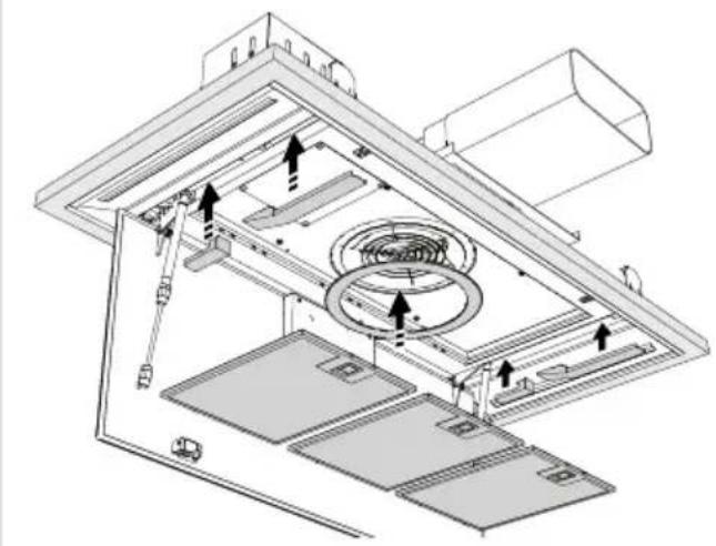
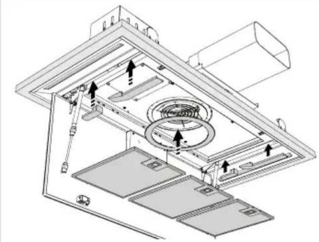
natural_image
Technical line drawing of an open refrigerator interior with ventilation ducts and doorways (no text or symbols)18
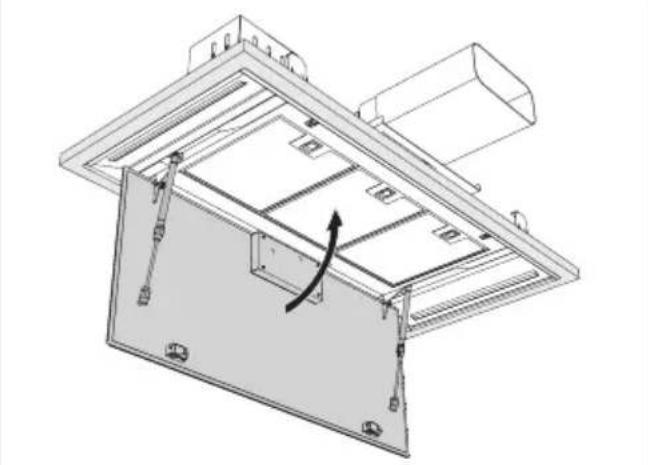
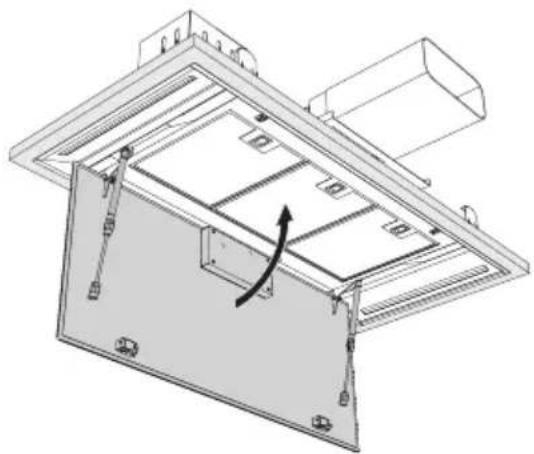
natural_image
Technical line drawing of a mechanical assembly with internal components and a curved arrow indicating motion (no text or symbols)19
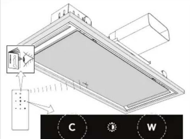
text_image
Technical diagram showing a device mounted on a panel with labeled components C and W, including directional arrows and a magnified inset of the device.Flexiblechannelinstallation
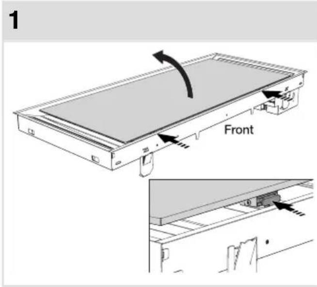
text_image
1 Front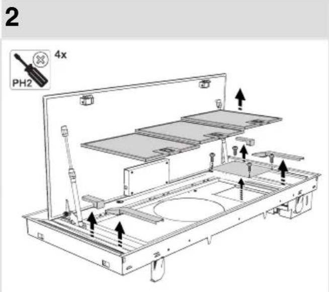
text_image
2 PH2 4x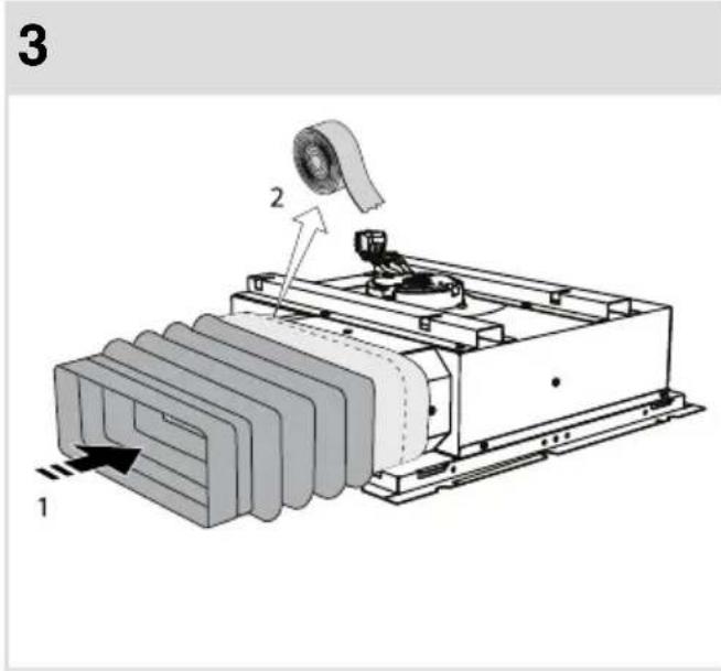
text_image
3 1 2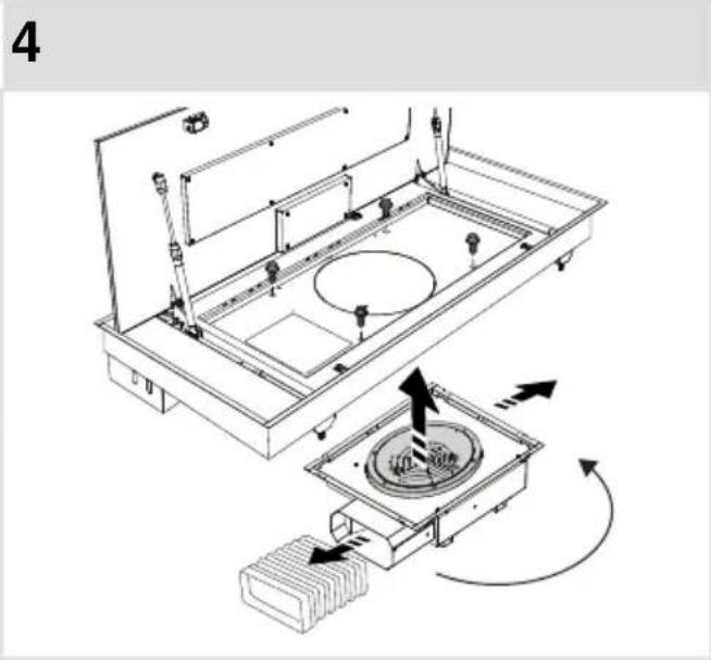
natural_image
Technical line drawing of a mechanical assembly with internal components and directional arrows (no text or symbols)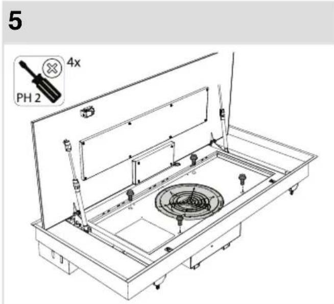
text_image
5 4x PH 2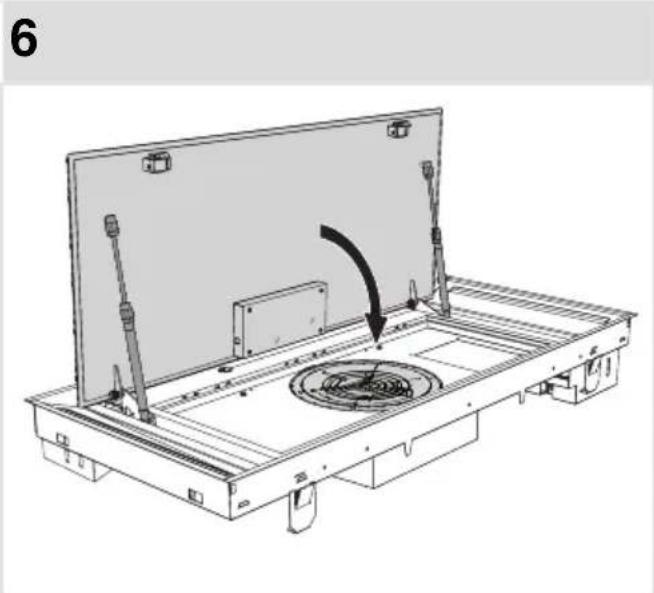
natural_image
Technical line drawing of a mechanical assembly with a rotating component and mounting bracket (no text or symbols)7
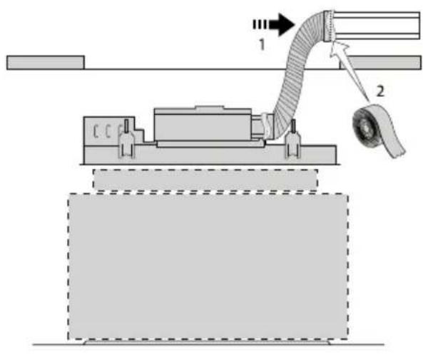
text_image
Technical diagram showing a mechanical assembly with labeled components and directional arrows indicating flow or movement.8
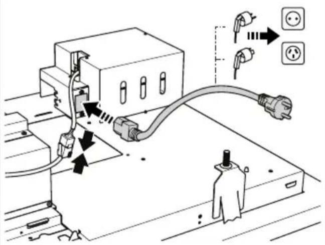
text_image
Diagram showing electrical connection with plug, socket, and power outlet, annotated with Chinese text and electrical symbols9
text_image
CLICK10
text_image
Max. 8 Nm 6 4x11
natural_image
Diagram of a rectangular panel with internal curved arrows indicating rotation or movement (no text or symbols)12
natural_image
Technical line drawing of a mechanical assembly with internal components (no text or symbols)Installation
13
natural_image
Technical line drawing of a mechanical assembly with a curved arrow indicating direction (no text or symbols present)14
text_image
Diagram illustrating a device with labeled components and directional arrows, including a control panel and a circular indicator system labeled C, W.Tipsforenergy-efficient cookingwithhoods
- Usealowextractorsettingandusethehighestsetting(boost)ifnecessary.
- Awell-ventilated kitchen make estherange hood more efficient.
- Clean filters regularly and replace filters when needed to keep the filter efficiency high, as a saturatedfiltercannotperformandstolongerusagetimes.
Disposal of the appliance and packaging
Sustainable material have been used during the manufacture of this appliance. This appliance must be disposed of responsibly at the end of its service life. Ask your local authorities for more information about how to do this.
The appliance packaging is recyclable. The following may have been used:
- cardboard;
•polyethylenefilm(PE);
•CFC-freepolystyrene(PSrigidfoam).
Disposeofthesematerialsinaresponsiblemannerandinaccordancewithgovernmentregulations.
text_image
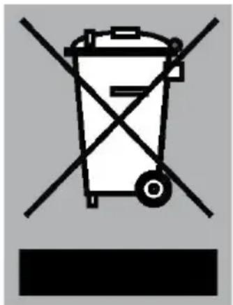
Warning symbol for a trash bin with crossed lines indicating no waste or discharge, and a black rectangular block below.Theproducthasbeenmarkedwithacrossed-outdustbinsymbolto remindyouoftheobligationtodisposeofelectricalhousehold appliancesseparately. Thismeansthattheappliancemaynotbe includedwithnormaldomesticrefuseattheendofitsservicelife. Theappliancemustbetakentoaspecialmunicipalcentreforseparated wastecollectionortoadealerprovidingthisservice.
Aseparate collection of household appliances help stop prevent any potential negative impact on the environment and human health caused by improper disposal. It ensures that them also of which the appliance is composed can be recovered to obtain significant savings in energy and raw materials.
CE
Declarationofconformity
WeherebydeclarethatourproductssatisfytheapplicableEuropean directives, ordersandregulations, aswellastherequirementsstated inthereferencedstandards.
ATAG
www.atag.nl
www.atag.be