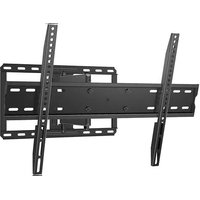
QLF315-B2 - Wall mount Secura - Free user manual and instructions
Find the device manual for free QLF315-B2 Secura in PDF.


User questions about QLF315-B2 Secura
0 question about this device. Answer the ones you know or ask your own.
Ask a new question about this device
Download the instructions for your Wall mount in PDF format for free! Find your manual QLF315-B2 - Secura and take your electronic device back in hand. On this page are published all the documents necessary for the use of your device. QLF315-B2 by Secura.
USER MANUAL QLF315-B2 Secura
natural_image
Technical line drawing of a mechanical assembly with two metal brackets and mounting holes (no text or symbols)Let Us Help
If you have any questions along the way, just give us a call.
P: +31 (0) 495 580 852 • UK: 0800 056 2853 • AUS: +61 (0) 7 3299 7000
For HeightFinder™, MountFinder™ and Mount Info,
Scan or visit san.us/2744
CAUTION: IMPORTANT SAFETY INSTRUCTIONS — PLEASE READ ENTIRE MANUAL PRIOR TO USE — SAVE THESE INSTRUCTIONS
Before getting started, let's make sure this mount is perfect for you!
| 1 Does your TV (including accessories) weigh MORE than 80 lbs. (36.2 kg)? | 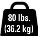 No? Perfect - you may continue.Yes? This mount is NOT compatible.Visit secura-av.com or call P: +31 (0) 495 580 852• UK: 0800 056 2853 • AUS: +61 (0) 7 3299 7000 to find a compatible mount. No? Perfect - you may continue.Yes? This mount is NOT compatible.Visit secura-av.com or call P: +31 (0) 495 580 852• UK: 0800 056 2853 • AUS: +61 (0) 7 3299 7000 to find a compatible mount. | CAUTION: DO NOT exceed the maximum weight indicated. This mounting system is intended for use only with the maximum weights indicated. Use with products heavier than the maximum weights indicated may result in collapse of the mount and its accessories, causing possible injury. | ||||
| 2 What is your wall made of? | all with I studs?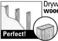 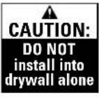 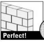 Solid concrete or concrete block? Solid concrete or concrete block? Call Customer Service:P: +31 (0) 495 580 852• UK: 0800 056 2853• AUS: +61 (0) 7 3299 7000 Call Customer Service:P: +31 (0) 495 580 852• UK: 0800 056 2853• AUS: +61 (0) 7 3299 7000 | |||||
| 3 Do you have all the tools needed? | 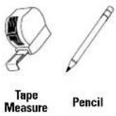 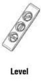 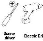 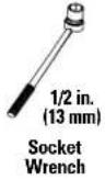 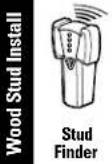 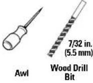 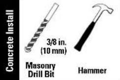 | |||||
| 4 Ready to begin? | Please read through these instructions completely to be sure you're comfortable with this easy install process.Also check your TV owner's manual to see if there are any special requirements for mounting your TV.If you do not understand these instructions or have doubts about the safety of the installation, assembly or use of this product, contact Customer Service at P: +31 (0) 495 580 852 • UK: 0800 056 2853 • AUS: +61 (0) 7 3299 7000. | |||||
| CAUTION: Avoid potential personal injury or property damage!This product is designed for use in wood stud, solid concrete, and concrete block walls - DO NOT install into drywall aloneThe wall must be capable of supporting five times the weight of the TV and mount combinedDo not use this product for any purpose not explicitly specified by manufacturerManufacturer is not responsible for damage or injury caused by incorrect assembly or use | ||||||
Dimensions in. [mm]
TV INTERFACE
![Secura QLF315-B2 - Dimensions in. [mm] - 1](/content/2026/04/696253/images/3fe17448918ec0928e09fbd7b6e96e6c56c238d83ed7d6fc9c122c7cdb5a6b76.jpg)
text_image
24.43 [620.4] φ 0.33 [8.5] 16.93 [430.0] 3.94 [100.0] 1.02 [26.0]WALL PLATE
![Secura QLF315-B2 - Dimensions in. [mm] - 2](/content/2026/04/696253/images/e51d39c998374dad6ffd3cfe904dce58415ed43546671de8607a822c425a2991.jpg)
text_image
Ø0.33 [8.5] 6.30 [160.0] 8.88 [225.5] 7.78 [197.5] 10.02 [254.5] 16.00 [406.4] 17.72 [450.0]FULLY ASSEMBLED MOUNT
![Secura QLF315-B2 - Dimensions in. [mm] - 3](/content/2026/04/696253/images/f41739eaa8cfdffcc97f226ac1f275bfa4362598433494a2778f9b4b94bb3c06.jpg)
text_image
25.59 [650.0] 16.93 [430.0] :5 POST INSTALL ROLL CONTROLTOP VIEW - EXTENDED
![Secura QLF315-B2 - Dimensions in. [mm] - 4](/content/2026/04/696253/images/f95e674ef124d6a8ef962d7e4b68b82c5aac0928fdbdee5d7a7aaa45e7fa6947.jpg)
text_image
25° TO 45°TOP VIEW - RETRACTED
![Secura QLF315-B2 - Dimensions in. [mm] - 5](/content/2026/04/696253/images/f73552daa47a4602edf51dc65c4e2b3db7bfe19f251c5955e4f7dad32d4bd032.jpg)
3-D
![Secura QLF315-B2 - Dimensions in. [mm] - 6](/content/2026/04/696253/images/e404b1d49c4e85e5624d1ad7de4931535a006c7d73676c748caa510c02595fa7.jpg)
SIDE VIEW - EXTENDED
![Secura QLF315-B2 - Dimensions in. [mm] - 7](/content/2026/04/696253/images/ace5e564afea93149f6f03025cc329d2e35950854791a8edd42589a92acac4c7.jpg)
text_image
15° 10° 14.21 [360.9]SIDE VIEW - RETRACTED
![Secura QLF315-B2 - Dimensions in. [mm] - 8](/content/2026/04/696253/images/760ec03887ea8c807f3efecddc5440968fd1ad7174f209cd766c42ea0aaff5fe.jpg)
Supplied Parts and Hardware
▲ WARNING: This product contains small items that could be a choking hazard if swallowed.
Before starting assembly, verify all parts are included and undamaged. If any parts are missing or damaged, do not return the damaged item to your dealer; contact Customer Service. Never use damaged parts!
NOTE: Not all hardware included will be used.
STEP 1 Parts and Hardware
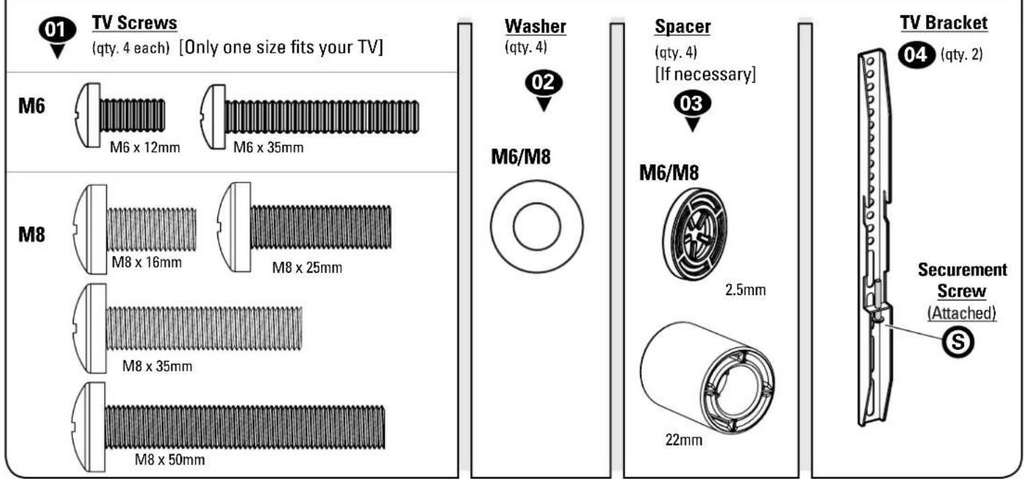
text_image
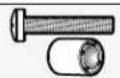
01 TV Screws (qty. 4 each) [Only one size fits your TV] M6 M6 x 12mm M6 x 35mm M8 M8 x 16mm M8 x 25mm M8 x 35mm M8 x 50mm Washer (qty. 4) 02 M6/M8 Spacer (qty. 4) [If necessary] 03 M6/M8 2.5mm 22mm TV Bracket 04 (qty. 2) Securement Screw (Attached) SSTEP 2 Parts and Hardware
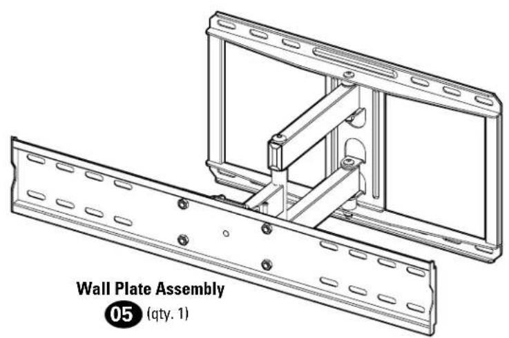
text_image
Wall Plate Assembly 05 (qty. 1)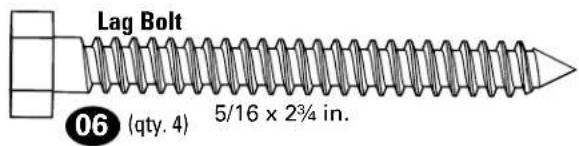
text_image
Lag Bolt 06 (qty. 4) 5/16 x 2¾ in.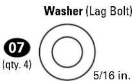
text_image
Washer (Lag Bolt) 07 (qty. 4) 5/16 in.For concrete installations ONLY
CAUTION: Do not use in drywall or wood
08(qty.4)
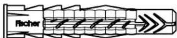
Fischer UX 10 x 60R
STEP 1 Attach Brackets to TV
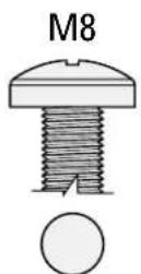
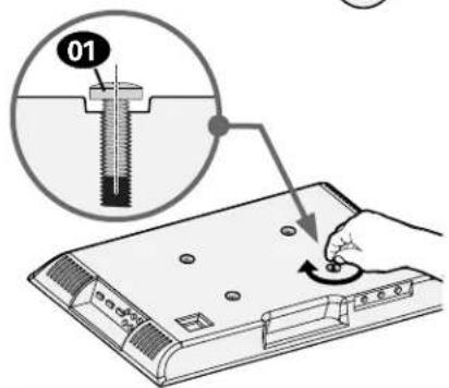
Only one screw size fits your TV.

text_image
011.2 Select TV Screw Length and Spacers1.1 Select TV Screw Diameter

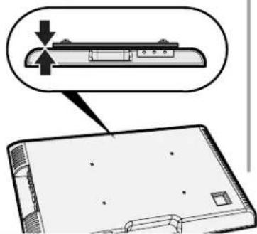
[TV brackets lay flat on your TV]
Use short TV screws 01 Spacers 03 not needed.

- Flat Back TV with Extra Space Needed
[for deep inset holes or cable interference]
• Rounded or Irregular Back TV
[TV brackets NOT resting flat on your TV]
Use long TV screws 01 and spacers 03 to create extra space between the TV and TV bracket.
natural_image
Diagram showing a device with a lock and a magnified view of its internal structure (no text or symbols)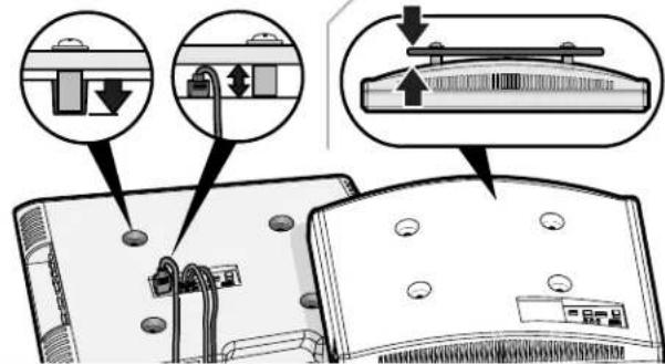
text_image
Diagram illustrating cable installation steps with labeled components and directional arrows▲ CAUTION: Verify adequate thread engagement with your screw 01, washer 02, spacer 03 combination AND TV bracket 04. — Too short will not hold your TV. — Too long will damage your TV.
Too Short
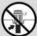
Too Long
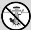
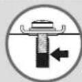
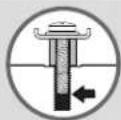
1.3 Attach TV Brackets to Your TV
Level and center your TV brackets 04 over your TV's mounting hole pattern, and install using the screw combination A or B you selected.
▲ CAUTION: Avoid potential personal injuries and property damage! DO NOT use power tools for this step. Tighten the screws 01 only enough to secure the TV bracket 04 to the TV. DO NOT overtighten the screws.
IMPORTANT: Ensure TV bracket 04 is securely fastened before moving on to the next step.
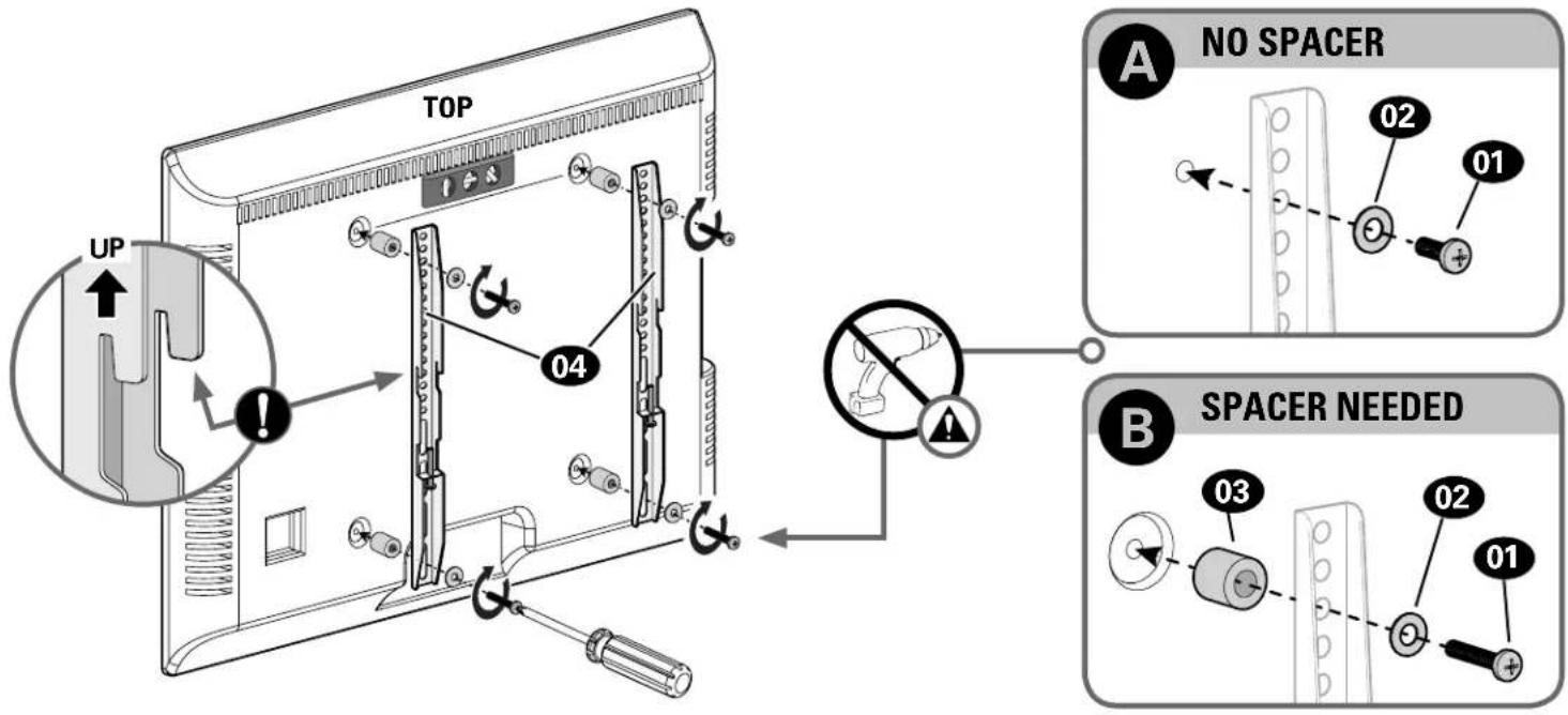
text_image
TOP A NO SPACER 02 01 B SPACER NEEDED 03 02 01STEP 2A Attach Wall Plate

Wood Stud Installation
CAUTION: Avoid potential personal injury or property damage!
• Drywall covering the wall, must not exceed 5/8 in. (16 mm)
• Minimum wood stud size: nominal 2 x 4 in. (51 x 102 mm) actual 1½ x 3½ in. (38 x 89 mm)
• Stud center must be verified
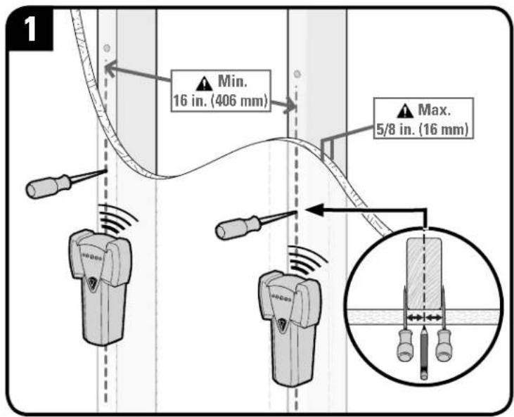
text_image
1 Min. 16 in. (406 mm) Max. 5/8 in. (16 mm)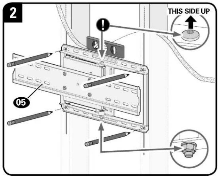
text_image
2 05 THIS SIDE UP▲ CAUTION: Avoid potential injuries or property damage! Improper use could reduce the holding power of the lag bolts 06. Do not over-tighten the lag bolts 06.
Go to STEP 3 on PAGE 12.
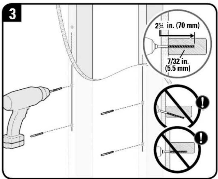
text_image
3 2¾ in. (70 mm) 7/32 in. (5.5 mm)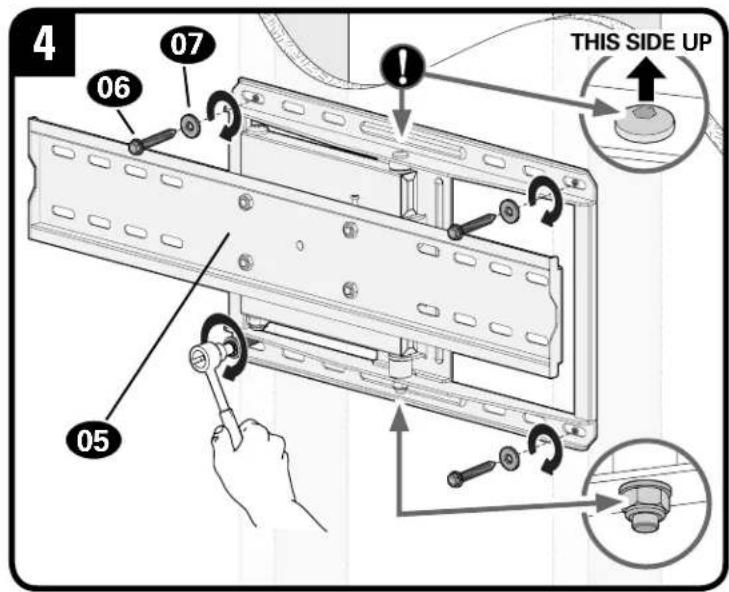
text_image
4 06 07 ! THIS SIDE UP 05STEP 2B Attach Wall Plate

Solid Concrete or Concrete Block Option
CAUTION: Avoid potential personal injury or property damage!
- Mount the wall plate assembly 05 directly onto the concrete surface
• Minimum solid concrete thickness: 8 in. (203 mm)
● Minimum concrete block size: 8 x 8 x 16 in. (203 x 203 x 406 mm)
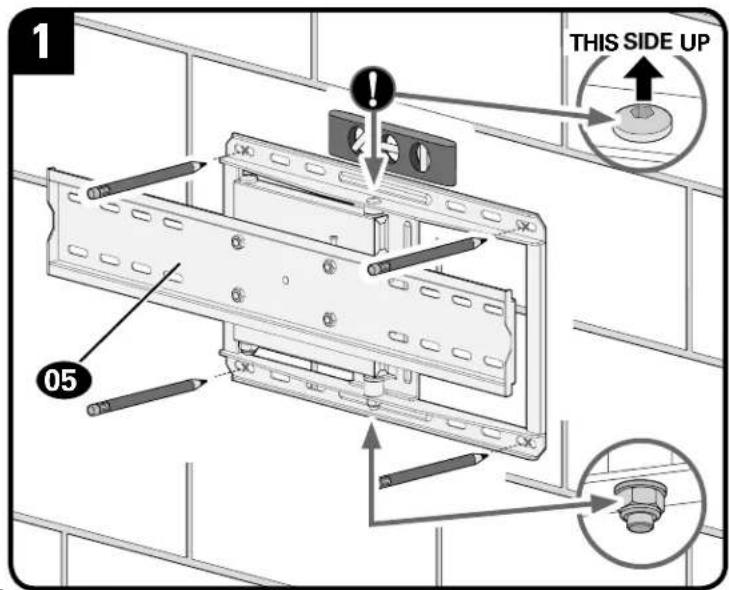
text_image
1 05 THIS SIDE UP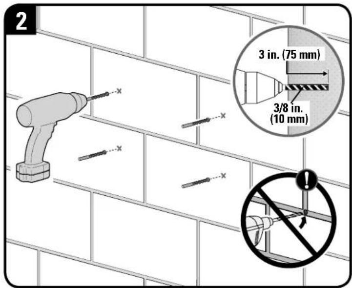
text_image
2 3 in. (75 mm) 3/8 in. (10 mm)▲ CAUTION: Avoid potential injuries or property damage! Improper use could reduce the holding power of the lag bolts 06 Do not over-tighten the lag bolts 06.
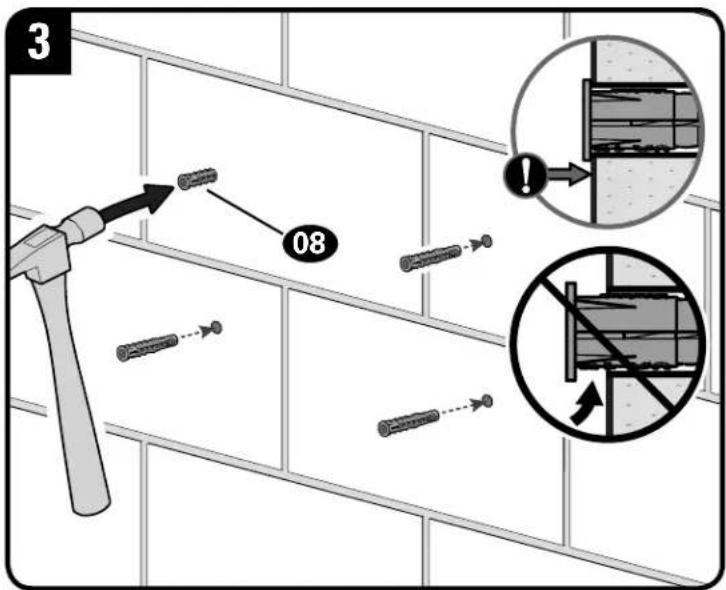
text_image
3 08
text_image
4 07 06 ! THIS SIDE UP 05STEP 3 Attach TV to Wall Plate

HEAVY! You may need assistance with this step.

CAUTION:
Avoid potential personal injuries and property damage!
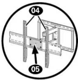
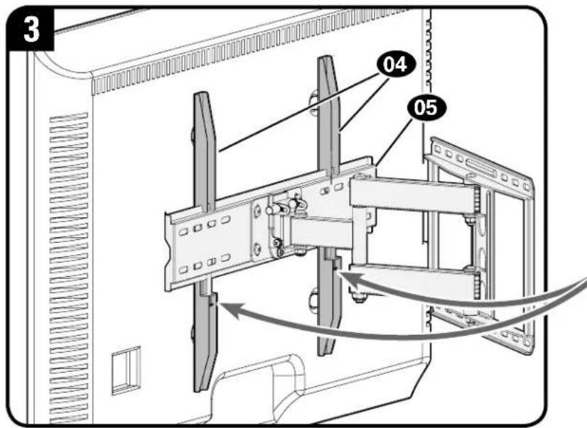
TV brackets 04 must be centered AND span the faceplate of wall plate assembly 05.
text_image
04 05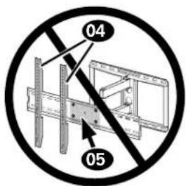
text_image
04 05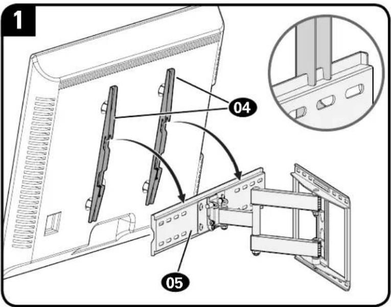
text_image
1 04 05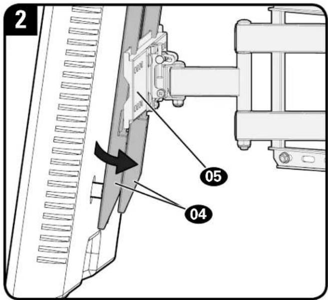
text_image
2 05 04IMPORTANT: You may need to back out locking screws Ⓢ to allow the TV brackets 04 to rest flat against the wall plate assembly 05.
CAUTION: Avoid potential personal injury or property damage! Locking screws Ⓢ must be tightened BEHIND wall plate assembly 05, to secure the TV in place.
text_image
3 04 05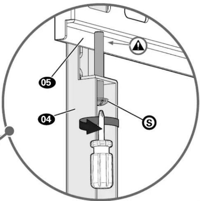
text_image
05 04 STV Adjustments

TILT ADJUSTMENT
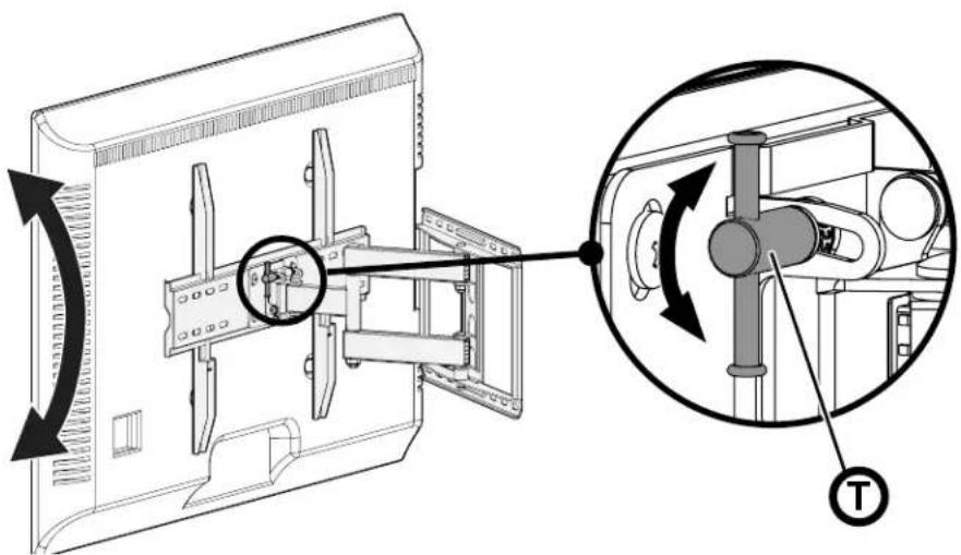
To adjust the tilt level of your TV, loosen the tilt adjustment knob Ⓣ, adjust the TV to the desired tilt angle and retighten the tilt adjustment knob Ⓣ.
NOTE: Once your TV is in place, tighten the tilt adjustment knob T to prevent unwanted movement.
text_image
Technical diagram showing mechanical assembly with labeled component T and directional arrows indicating rotation or movement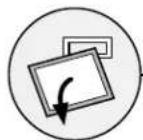
REMOVING THE TV

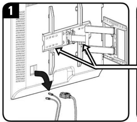
HEAVY! You may need assistance with this step.
text_image
1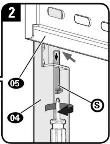
text_image
2 05 04 S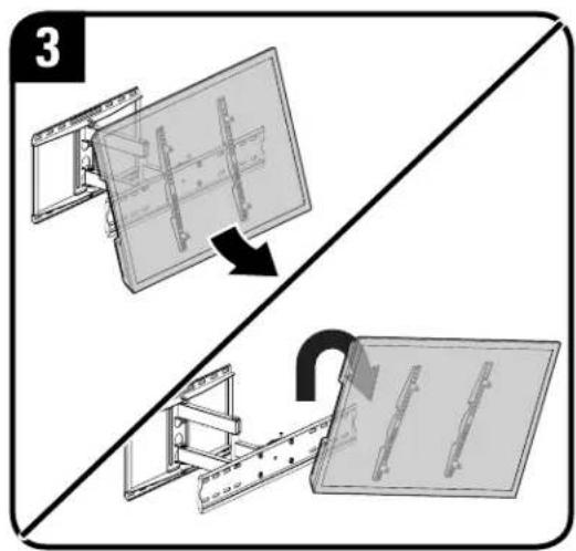
text_image
3ESPAÑOL
natural_image
Four technical illustrations of electrical components: a remote control switch, screwdriver, pencil, and three circular buttons (no text or symbols)m = 311
дереву
бетону
гаечный ключ
4
Готовы начать?
Milestone Global Headquarters
6436 City West Parkway
Eden Prairie, MN 55344 USA
P: 800-359-5520
info@milestone.com
Milestone AV Technologies EMEA Headquarters
Franklinstraat 14
6003 DK Weert,
Netherlands
P: +31 (0) 495 580 852
UK: 0800 056 2853
sanus.europe@milestone.com
Milestone AV Technologies Australia Office
Unit 20 / 33 Meakin Road
Meadowbrook QLD 4131,
Australia
P: +61 (0) 7 3299 7000
Milestone AV Technologies and its affiliated corporations and subsidiaries (collectively, "Milestone"), intend to make this manual accurate and complete. However, Milestone makes no claim that the information contained herein covers all details, conditions, or variations. Nor does it provide for every possible contingency in connection with the installation or use of this product. The information contained in this document is subject to change without notice or obligation of any kind. Milestone makes no representation of warranty, expressed or implied, regarding the information contained herein. Milestone assumes no responsibility for accuracy, completeness or sufficiency of the information contained in this document.
©2018 Milestone AV Technologies. All Rights Reserved. Secura is a brand of Milestone. Secura, the Secura logo, HeightFinder and MountFinder are trademarks of Milestone.
Milestone Global Headquarters • 6436 City West Parkway • Eden Prairie, MN 55344 USA
6901-602344 00