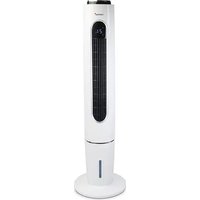
81503 - Fan KORONA - Free user manual and instructions
Find the device manual for free 81503 KORONA in PDF.


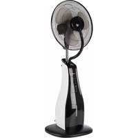
| Product type | 4-in-1 tower fan (fan, humidifier, cooler, purifier) |
| Brand | Korona |
| Model | 81503 |
| Power supply | 220-240 V~ 50/60 Hz |
| Power | 65 W |
| Water tank capacity | 3 L |
| Protection class | II |
| Maximum air flow | 2.8 m³/min |
| Fan input power | 43.4 W |
| Service value | 0.06 (m³/min)/W |
| Standby consumption | 0.37 W |
| Seasonal consumption | 14.3 kWh/a |
| Noise level | 64.7 dB(A) |
| Maximum air speed | 1.38 m/s |
| Number of speeds | 3 (Low, Medium, High) |
| Wind modes | Normal, Natural, Sleep |
| Timer | 1 to 12 hours |
| Functions | Ventilation, Cooling (ice packs), Humidification, Purification (Anion) |
| Remote control | Yes, with CR2025 battery |
| Ice packs included | 4 |
| Warranty | 2 years |
| Maintenance | Clean with a damp cloth; removable grille filter |
Frequently Asked Questions - 81503 KORONA
User questions about 81503 KORONA
0 question about this device. Answer the ones you know or ask your own.
Ask a new question about this device
Download the instructions for your Fan in PDF format for free! Find your manual 81503 - KORONA and take your electronic device back in hand. On this page are published all the documents necessary for the use of your device. 81503 by KORONA.
USER MANUAL 81503 KORONA
4 in 1 Turmventilator
English
Instruction Manual
4 in 1 Tower Fan
Nederlands
Handleiding
4-in-1 Torenventilator
Français
KORONA electric GmbH, Sundern/Germany
www.korona-electric.de
Bedienungsanleitung
natural_image
Circular mechanical component with central hole and flanges (no visible text or symbols)natural_image
Close-up of a metallic cylindrical component with mounting holes and directional arrows indicating rotation or force (no text or symbols)natural_image
Close-up of a mechanical component with a central shaft and circular base, showing fluid or material flow (no text or symbols visible)natural_image
Mechanical component with circular housing and directional arrows indicating motion (no text or symbols)natural_image
Close-up of a white cylindrical object with a glass pipette inserted, no visible text or symbolsnatural_image
Exterior view of a tall cylindrical air conditioner unit with grid-patterned panel and base (no visible text or symbols)natural_image
Close-up of hands installing or adjusting a white cylindrical device with a grid of small square cutouts (no visible text or symbols)natural_image
Three views of a corrugated metal structure with ribbed and grid-like panels, shown from different angles (no text or symbols visible)Read these instructions carefully before assembling and/or operating the appliance. Keep these instructions including warranty, receipt and, if possible, the box with the internal packing.
When passing on the appliance to a third party, make sure to include these instructions for use.
Intended Use
This appliance is intended for household use only and not for commercial, industrial or outdoor use. Other use not recommended may cause fire, electric shock or injury.
Safety:

This symbol identifies hazards which may cause injuries!

This symbol identifies electric shock hazards!

This symbol identifies tips and information.
Important safety instructions

Warning! To avoid the possibility of injury/damage to the appliance, electric shock and risk of fire.
Danger of injury and damage to the appliance!
- Manufacturer takes no responsibility for any damage caused by incorrect use.
- Incorrect or improper use can damage the appliance and cause injuries to the user.
- Before connecting this appliance to the mains, make sure your local voltage matches the technical data of the appliance. Otherwise the appliance may overheat and get damaged.
- Do avoid contact with all moving parts. Always wait until all moving parts have come to stand still before touching them.
- Do not insert fingers or allow foreign objects to enter the grill/ air outlet.
- Make sure the fan is not placed near drapes, curtains, or any objects that may be drawn (including hair and clothes) into the fan.
- Make sure to place the fan on an even surface, as water may flow out of the water tank.
- Never place or operate the unit where it could be subject to:
- Heat sources such as radiators, heat registers, stoves or other products that produce heat
- Direct sunlight
- Excessive dust
- Mechanical vibration or shock
- Lack of ventilation
- Uneven surfaces, to avoid the tipping of the fan during use
- Always turn OFF and unplug the fan when not in use and/or when moving it from one location to another.
Caution! Danger of electric shock!
- Never put the appliance, cord or plug into water or any other liquid.
- Do not use the appliance near a sink or wash basin.
• Do not use the appliance with wet hands.
• Do not use the appliance outdoors.
An electric appliance is not a toy!
• Never leave the appliance unattended during use.
- This appliance can be used by children aged from 8 years and above and persons with reduced physical, sensory or mental capabilities or lack of experience and knowledge if they have been given supervision or instruction concerning the use of the appliance in a safe way and understand the hazards involved. Children shall not play with the appliance. Cleaning and user maintenance shall not be made by children unless they are older than 8 and supervised.
- Keep the appliance and its cord out of reach of children less than 8 years.
• Always unplug your appliance when it is not in use, and before cleaning.
• Always pull the plug – not the cord.
- Keep the appliance and the cord well away from any hot surfaces to avoid any damage to the appliance.
- Do not run cord under carpeting. Make sure the cord may not inadvertently be pulled or cause anyone to trip when in use.
- Do not allow the cord to hang over sharp edges.
- Do not bend the cord or wind it round the appliance.
Do not use the appliance,
• if the cord is damaged.
• in case of malfunction.
- if the appliance was dropped or is damaged otherwise. Have it checked and, if necessary, repaired by a qualified person/Customer Service. Never attempt to make any modifications to or repair the appliance yourself.
• Only use accessories evaluated for use with this appliance.
- Never attempt to drive any objects into the appliance.
• Never attempt to open the housing yourself!
- The appliance is not intended to be operated by means of an external timer or separate remote-control system.
Notes on handling batteries

Warning:
- Swallowing batteries can be extremely dangerous. Keep the batteries out of the reach of small children. Should a child swallow a battery, seek medical assistance, immediately.
- Batteries must not be recharged, taken apart, thrown into an open fire or short circuited. Risk of fire/explosions!
- Always replace all batteries at the same time and always use the same battery type.
- Batteries can contain toxins that are harmful to your health and the environment. Always dispose of batteries in accordance with applicable legal regulations. Do not dispose of batteries with the normal household waste.
Scope of delivery
1 tower fan
1 remote control
4 ice pack
1 instruction manual
Description of parts
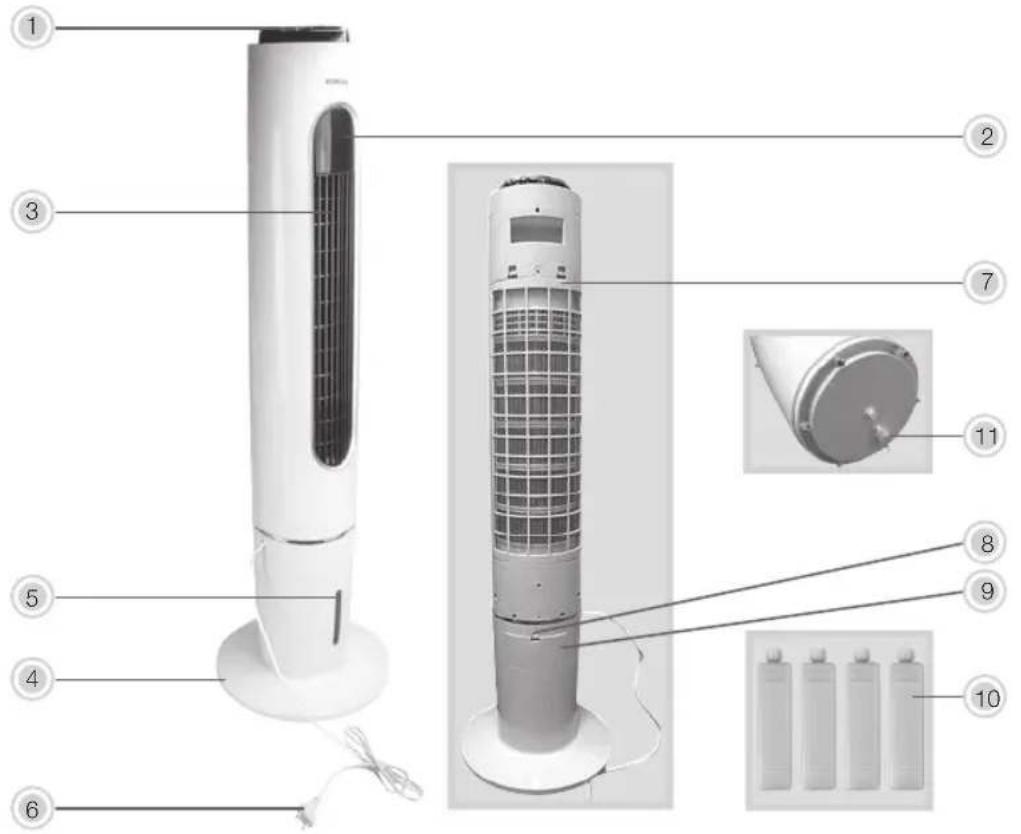
- Control Panel
- LED Monitor
- Air Outlet
- Base (2 parts)
- Water Level Indication
- Power Cord and Plug
- Filter Grill
- Water Tank Latch
- Detachable Water Tank Cover
- Ice pack (x4)
- Water Drainage
- Remote Control
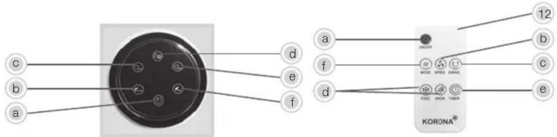
Control Panel / Remote Control Settings
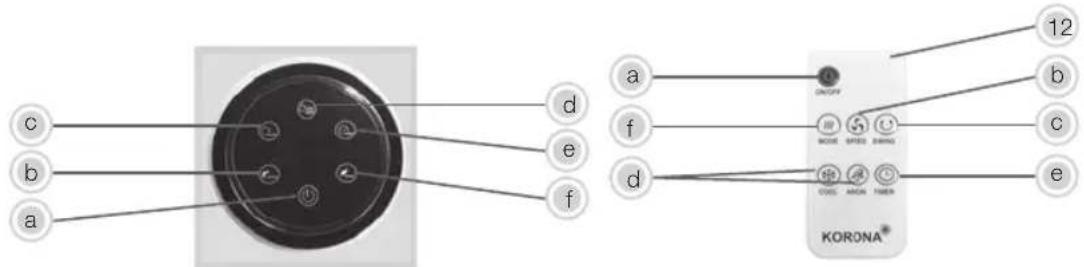
a. On/Off button
- Allows 3 different speed level selections.
Low - Medium - High
c. Swing button
- Turns oscillation on / off
d. Cool/Anion button
Control panel
- Press once to start the cooling function, ice packs must be added
- Press twice to start the anion function (air cleaning function)
- Press three times, cooling and anion function will be activated
- Press four times, function will be shut off.
Remote Control
- Cooling and Anion function are two separate function keys.

By each press the respective symbol is shown on the display.

Warning: Always make sure that there is enough water in the water tank, before pressing the cool/y. Do not activate this function with an empty water. This might damage the appliance.
e. Timer button
- Allows for automatic shut off. Time increases by one hour with each push of the button, up to 12 hours.
f. Mode button
- Allows for up to 3 wind modes.
Normal: The fan runs according to the set speed setting (Low - Medium - High)
Natural: The fan runs according to a pre-determined program which varies according to which speed is selected. This setting will enable you to enjoy a nice, natural breeze.
Sleep: The fan runs according to a pre-determined program; the fan will gradually slow down and remain at low setting. We recommend to choose the low speed setting.

Before first use of the remote control, remove the protective sheet from the button cell.
Before first use
- Remove all packaging material and check whether the appliance is complete and that all accessories are included.
• Fully unwind the power cord. - Clean the appliance as described under Cleaning and Care.

If any items are damaged or missing, contact your dealer or customer service.

Warning: Plastic bags are a danger to toddlers and babies, therefore keep them away to avoid on.
Assembly
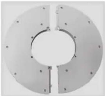
- Turn the two parts of the base upside down and attach part 1 to part 2 by aligning the holes onto the posts. Make sure that the two base parts are securely attached.
natural_image
Circular mechanical component with central hole and flanges (no text or symbols visible)- Remove the screws from the base of the product.
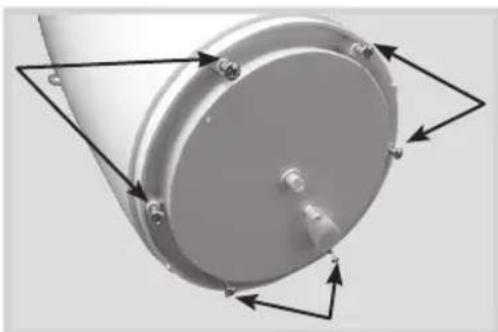
natural_image
Close-up of a metallic cylindrical component with mounting holes and directional arrows indicating rotation or force (no text or symbols)- Align the base and insert the fan body into the opening of the top of the base.

natural_image
Close-up of a mechanical component with a central shaft and circular base, showing fluid or material flow (no text or symbols visible)- To fully secure the fan body to the base, insert the screws into the holes of the base and tighten them.
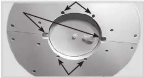
natural_image
Mechanical component with circular housing and mounting holes, showing directional arrows indicating motion (no text or symbols)Filling the water tank with water

Always make sure that the appliance is not connected to the mains when filling the water
tank.
Make sure that the appliance is standing upright and placed on a flat and stable surface.
- Open the cover of the water tank.
- Add water.
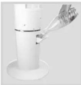
natural_image
Close-up of a white cylindrical object with a glass pipette inserted, no visible text or symbols- Close the cover of the water tank.
- Always make sure to adhere to the Min. and Max. Water level.

We recommend to only add 3 L Max.
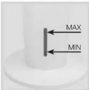

Only fill water into the water tank. Do not use any chemicals or other liquids in the water
tank!

Always make sure that when using the cool/anion and humidifying function the water level should never go over the Max nor under the MIN level.
Draining out the water
Always use the drain hole which at the bottom of the fan.
Do not over tilt the fan when draining out the water so that to avoid from water leakage from the water tank entrance.
Using the ice pack

The ice packs should be used if you wish to increase the cooling effect of the fan.
- Completey remove the cover of the water tank and place the ice packs into the water tank. Make sure that water is added, reaching the max. level.
- Reinsert the cover of the water tank and close it.

We recommend to only use two ice packs at a time.

Before the ice packs can be used they need to be filled with water and placed into the until the water is frozen. Never fill in any other liquids or chemicals into the ice packs.
Operation
The fan can be used as a fan, humidifier, air cooler and air purifier by using the anion function.

Always ensure that the fan is unplugged from the power supply and turned off before facing with the assembly process.

Make sure that the fan is properly assembled before operation.

The appliance can be operated via the control panel as well as by remote control.
- Place your fan on an even, dry and stable surface and plug it into a proper power socket.

Make sure your local voltage matches the technical data of the appliance. Otherwise the appliance heat and get damaged.
Adhere to a safety distance to walls and other objects.

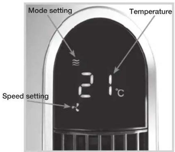
When first switched on the appliance will operate in low speed in normal mode and the LED display will show the current room temperature.
- Choose your desired settings by pressing the respective buttons and until the respective symbol appears on the display.
Example: Temperature, Mode, Speed Display
- After use, switch off the appliance and unplug it.

Never leave the appliance unattended during use.

Always remove the battery from the remote control if it will not be used for a longer period of time.
Replacing the battery of the remote control
Only use 3V CR2025 Lithium button cell!
-
To open the battery compartment, press onto the battery compartment lock and pull out the battery holder.
-
Insert a new CR2025 battery with the + sign at the top.
-
Re-insert the battery holder into the remote control. Make sure that the battery holder is properly inserted into the remote control.
Cleaning and Care
Before cleaning, always switch off the appliance and disconnect it from the mains.
Never immerse the appliance in water. Danger! Electric Shock!
- Clean the appliance using a a soft damp cloth.
- Never spray the appliance with liquids or submerge it in water or other liquid.
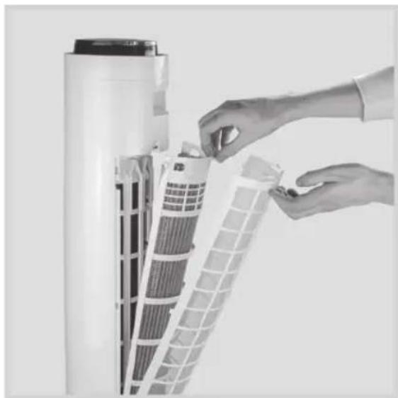
- For cleaning purpose, the filter grill can be removed.
After the cleaning process is finished and before reassembling the filter grill make sure that all parts are dry.

Never use alcohol, gasoline, and/or any other aggressive cleaning agents/hard objects.
Removing the filter grill for cleaning
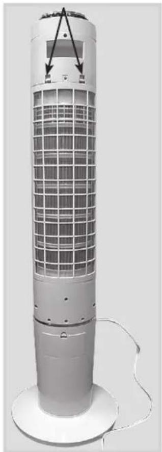
- Remove the screws and push down the two snap tabs to remove the outer grid.
natural_image
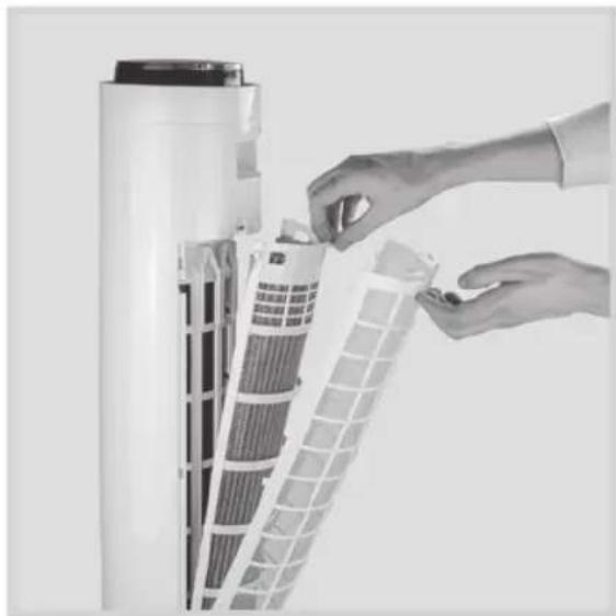
Exterior view of a tall industrial air conditioner tower with grid-patterned ventilation grille and base mount (no text or symbols visible)- Remove the filter grill from appliance.
natural_image
Close-up of hands installing or adjusting a white plastic component with grid patterns (no visible text or symbols)- Remove the filter from the grill.
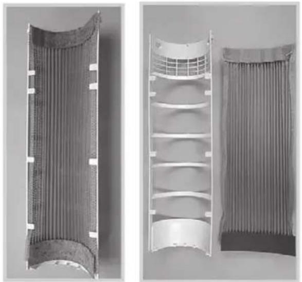
natural_image
Two views of a corrugated heat exchanger or filter structure, showing internal structure and top-down view (no text or symbols visible)
Cleaning and user maintenance shall not be made by children without supervision.
Storage
Keep the appliance away from children and store it in a clean and dry place, best in its original box or cover it to protect it from dust.
Disposal Instructions
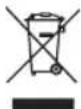
Waste electrical devices marked with this sign must not be disposed of with your household waste, but are to be collected separately. Therefore, please return this device at the end of its life cycle to special collection points for disposal or your local dealer.

Your 4 in 1 Tower Fan 81503 is packed in a retail box. Such boxes are recyclable waste, i.e. they are reusable or recyclable.
Disposal instruction for batteries

Standard and rechargeable batteries should not be thrown into regular household waste. As a ter, you are legally obliged to return used batteries for proper disposal. You can hand in your used at public collection points in your district or sales outlets where batteries of this type are sold.

Note: The codes below are printed on batteries containing harmful substances:
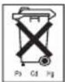
Pb = Battery contains lead
Cd = Battery contains cadmium
Hg = Battery contains mercury
Technical data
| Voltage: | 220 - 240 V | 50 / 60 Hz |
| Power: | 65 W | |
| Water tank capacity: | 3 L | |
| Protection class: | II |
| Description Symbol Value Unit | |||
| Maximum fan flow rate F 2.8 m3/min | |||
| Fan power input P 43.4 W | |||
| Service value SV 0.06 (m3/min)/W | |||
| Standby power consumption | PSB | 0.37 W | |
| Seasonal electricity consumption | Q | 14.3 kWh/a | |
| Fan sound power level | LWA | 64.7 dB(A) | |
| Maximum air velocity | C | 1.38 meter/sec | |
| Measurement standard for service value | ISO 5801:2007(E) | ||
NOTE: As a result of continual improvements, the design and specifications of the product within may differ slightly to the unit illustrated on the packaging.
Technical data subject to change!
CE
Guarantee:
This product is guaranteed against defects in materials and workmanship for a period of 2 years.
This guarantee is not valid:
- if the appliance has not been used in accordance to t instructions
• for damages due to wear and tear (batteries, etc.)
• for damages known by customer at time of purchase
• for damages caused by owner
This guarantee does not affect your statutory right, nor any legal right you may have as a customer under applicable national legislation governing the purchase of goods.
In order to assert his/her right in a guarantee case during the guaranteed period, the customer must provide evidence of the date of purchase (receipt).
The guarantee is to be asserted against
KORONA electric GmbH, Sundern/Germany.
Telephone Hotline: +49 2933 90284-80
Mail: service@korona-electric.de
web: www.korona-electric.de
within 2 years after the date of purchase. In case of guarantee the customer is given the right to get the appliance repaired at our own or at an authorized shop. Further rights (due to guarantee case) are not given to the customer.
Handleiding
- Bedieningspaneel
- LED-scherm
- Luchtuitlaat
- Voet (2 delen)
- Waterniveauanduiding
- Netsnoer en stekker
- Filterrooster
- Vergrendeling waterreservoir
- Afneembaar deksel waterreservoir
- Icepack (x4)
- Waterafvoer
- Afstandsbediening
Controlepaneel / Instellingen Afstandsbediening
a. Aan/Uit-knop
natural_image
Circular mechanical component with central hole and flanges (no text or symbols visible)natural_image
Close-up of a metallic cylindrical component with mounting holes and directional arrows indicating rotation or force (no text or symbols)natural_image
Close-up of a mechanical component with a central circular feature and a metallic rod inserted (no visible text or symbols)natural_image
Mechanical component with circular housing and directional arrows indicating motion (no text or symbols)natural_image
Close-up of a white cylindrical device with a glass pipette inserted, showing liquid level (no text or symbols visible)natural_image
Exterior view of a tall cylindrical air conditioner unit with grid-patterned panel and base (no text or symbols visible)natural_image
Close-up of hands installing or adjusting a grid-patterned device with a cylindrical component (no visible text or symbols)natural_image
Two views of a corrugated heat exchanger or filter structure, showing internal structure and top-down view (no text or symbols visible)
c. Bouton Swing (oscillation)
- Active/désactive l'oscillation
d. Bouton Cool/Anion
Panneau de contrôle
natural_image
Circular mechanical component with central hole and flanges (no text or symbols visible)natural_image
Close-up of a metallic cylindrical component with mounting holes and directional arrows indicating rotation or assembly (no text or symbols)natural_image
Close-up of a mechanical component with a central rotating shaft and circular base, showing fluid or material flow (no text or symbols visible)natural_image
Mechanical component with circular housing and directional arrows indicating motion (no text or symbols)natural_image
Close-up of a white cylindrical object with a glass pipette inserted, showing liquid level (no text or symbols visible)natural_image
Exterior view of a tall cylindrical air conditioner unit with grid-patterned panel and base (no text or symbols visible)natural_image
Close-up of hands installing or adjusting a grid-patterned device with a cylindrical component (no visible text or symbols)natural_image
Two views of a corrugated heat exchanger or filter structure, showing internal structure and top-down view (no text or symbols visible)
natural_image
Circular mechanical component with central hole and flanges (no text or symbols visible)natural_image
Close-up of a metallic cylindrical component with mounting holes and directional arrows indicating rotation or force (no text or symbols)natural_image
Close-up of a mechanical component with a central circular opening and a metallic rod inserted (no visible text or symbols)natural_image
Circular mechanical component with directional arrows indicating motion or force, no visible text or symbolsnatural_image
Close-up of a white cylindrical object with a metallic tip inserted, showing liquid level (no text or symbols visible)natural_image
Exterior view of a tall cylindrical air conditioner unit with grid-patterned panel and base (no text or symbols visible)natural_image
Close-up of hands installing or adjusting a grid-patterned device with a cylindrical component (no visible text or symbols)natural_image
Two views of a corrugated metal structure with grid patterns, shown from different angles (no text or symbols visible)
natural_image
Circular mechanical component with bolt holes and central hole, no visible text or symbolsnatural_image
Close-up of a metallic cylindrical component with mounting holes and directional arrows indicating rotation or force (no text or symbols)natural_image
Close-up of a mechanical component with a central circular feature and a metallic rod inserted (no visible text or symbols)natural_image
Mechanical component with circular housing and directional arrows indicating motion (no text or symbols)natural_image
Close-up of a white cylindrical object with a glass pipette inserted, no visible text or symbolsnatural_image
Exterior view of a tall cylindrical air conditioner tower with grid-patterned panel and base (no text or symbols visible)- Retire la rejilla del filtro del aparato.
natural_image
Close-up of hands installing or adjusting a white plastic bag with a filter, no visible text or symbolsnatural_image
Two views of a corrugated metal structure with grid patterns, shown from different angles (no text or symbols visible)
natural_image
Circular mechanical component with central hole and flanges (no text or symbols visible)natural_image
Close-up of a metallic cylindrical component with mounting holes and directional arrows indicating rotation or force (no text or symbols)natural_image
Close-up of a mechanical component with a central circular feature and a metallic rod inserted (no visible text or symbols)natural_image
Mechanical component with circular housing and directional arrows indicating motion (no text or symbols)Su tankinin suyla doldurulmasi

natural_image
Close-up of a white cylindrical object with a metallic tip inserted, showing liquid flowing from it (no text or symbols visible)natural_image
Exterior view of a tall cylindrical air conditioner unit with grid-patterned panel and base (no text or symbols visible)natural_image
Close-up of hands installing or adjusting a white plastic bag with a filter, no visible text or symbolsnatural_image
Two views of a corrugated heat exchanger or filter structure, showing internal structure and top-down view (no text or symbols visible)
natural_image
Circular mechanical component with central hole and flanges (no text or symbols visible)natural_image
Close-up of a metallic cylindrical component with mounting holes and directional arrows indicating rotation or force (no text or symbols)natural_image
Close-up of a mechanical component with a central circular feature and a metallic rod inserted (no visible text or symbols)natural_image
Mechanical component with circular housing and directional arrows indicating motion (no text or symbols)natural_image
Close-up of a white cylindrical object with a pointed tip inserted, showing liquid and a small container (no visible text or symbols)natural_image
Exterior view of a tall cylindrical air conditioner unit with grid-patterned panel and base (no text or symbols visible)natural_image
Close-up of hands installing or adjusting a white plastic bag with a filter, no visible text or symbolsnatural_image
Two views of a corrugated metal structure with grid patterns, shown from different angles (no text or symbols visible)
natural_image
Circular mechanical component with central hole and flanges (no text or symbols visible)natural_image
Close-up of a metallic cylindrical component with mounting holes and directional arrows indicating rotation (no text or symbols)natural_image
Close-up of a mechanical component with a central circular feature and a metallic rod inserted (no visible text or symbols)natural_image
Mechanical component with circular housing and mounting holes, showing directional arrows indicating motion (no text or symbols)natural_image
Close-up of a white cylindrical object with a glass pipette inserted, no visible text or symbolsnatural_image
Exterior view of a tall cylindrical air conditioner tower with grid-patterned panel and base (no text or symbols visible)natural_image
Close-up of hands installing or adjusting a white plastic bag with a filter, no visible text or symbolsnatural_image
Two views of a corrugated heat exchanger or filter structure, showing internal structure and top-down view (no text or symbols visible)
natural_image
Abstract geometric shape with curved and angular gray segments, no text or symbols presentRef: 81503/2021.12
- English
- Nederlands
- Français
- Bedienungsanleitung
- Intended Use
- Safety:
- Important safety instructions
- Caution! Danger of electric shock!
- An electric appliance is not a toy!
- Do not use the appliance,
- Notes on handling batteries
- Warning:
- Scope of delivery
- Control Panel / Remote Control Settings
- a. On/Off button
- c. Swing button
- d. Cool/Anion button
- Control panel
- Remote Control
- e. Timer button
- f. Mode button
- Assembly
- tank.
- tank!
- Replacing the battery of the remote control
- Only use 3V CR2025 Lithium button cell!
- Removing the filter grill for cleaning
- Guarantee:
- Handleiding
- a. Aan/Uit-knop
- Panneau de contrôle
Brand : KORONA
Model : 81503
Category : Fan