
Classic MSF07c - TV Stand SANUS - Free user manual and instructions
Find the device manual for free Classic MSF07c SANUS in PDF.

| Product type | TV wall mount |
| Brand | Sanus |
| Model | Classic MSF07c |
| Maximum supported weight | 15.8 kg (35 lb) |
| VESA compatibility | 75 x 75 mm to 200 x 200 mm (with extension plate for 200x200) |
| Wall type | Drywall with wooden studs (maximum drywall thickness: 16 mm) |
| Wall plate dimensions (approx.) | 45 x 20 cm |
| Material | Steel |
| Main features | Adjustable tilt, cable management, secure locking tab system |
| Power supply | None (mechanical) |
| Care and cleaning | Wipe with a soft, dry cloth. Do not use abrasive products. |
| Safety | Installation on wood studs required; do not exceed maximum load; use provided screws and anchors |
| Spare parts and repairability | Contact Sanus customer service at 1 800 359-5520 for spare parts |
| Warranty | 5 years (manufacturer's warranty) |
| Package contents | Wall plate, TV brackets, mounting hardware, 200x200 extension plate, installation guide |
Frequently Asked Questions - Classic MSF07c SANUS
User questions about Classic MSF07c SANUS
0 question about this device. Answer the ones you know or ask your own.
Ask a new question about this device
Download the instructions for your TV Stand in PDF format for free! Find your manual Classic MSF07c - SANUS and take your electronic device back in hand. On this page are published all the documents necessary for the use of your device. Classic MSF07c by SANUS.
USER MANUAL Classic MSF07c SANUS
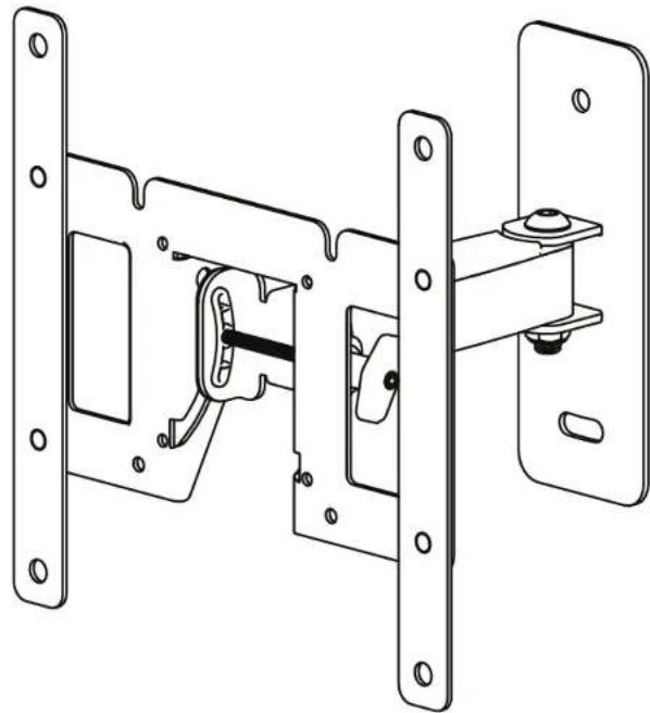
natural_image
Technical line drawing of a mechanical assembly with mounting brackets and a central component (no text or symbols)MSF07c Instruction Manual
IMPORTANT SAFETY INSTRUCTIONS – SAVE THESE INSTRUCTIONS – PLEASE READ ENTIRE MANUAL PRIOR TO USE
Before getting started, let's make sure this mount is perfect for you!
1
Does your TV weigh more than 35 lb (15.8 kg) including accessories?
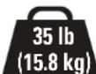
No — Perfect!
Yes — This mount is NOT compatible. Visit MountFinder.Sanus.com or call 1-800-359-5520 (UK: 0800-056-2853) to find a compatible mount.
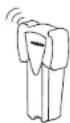
2

Drywall with
wood studs?
Perfect!

Unsure?
Call 1-800-359-5520
(UK: 0800-056-2853)
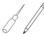
3
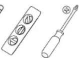
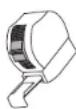
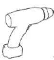
Do you have all of the tools needed?

4
Ready to begin?
Please read through these instructions completely to be sure you're comfortable with this easy install process. Also check your TV owner's manual to see if there are any special requirements for mounting your TV.
If you do not understand these instructions or have doubts about the safety of the installation, assembly or use of this product, contact Customer Service at 1-800-359-5520 (UK: 0800-056-2853).
▲ CAUTION: Avoid potential personal injuries and property damage!
- This product is designed for use in wood stud walls - DO NOT install into drywall alone
- The wall must be capable of supporting five times the weight of the TV and mount combined
- Do not use this product for any purpose not explicitly specified by manufacturer
- Manufacturer is not responsible for damage or injury caused by incorrect assembly or use
Dimensions
![in. [mm] 7.87 [200.0] 3.94 [100.0] 2.95 [75.0] 6.87 [174.6] 2.95 [75.0] 3.94 [100.0] 7.87 200.0 4.75 [120.7] 8.87 [225.4] 4.70 [119.3] OFFSET 2.56 [65.0] 8.80 [223.6]](/content/2026/04/694717/images/9614191ed53040133c83935b02a87baf502dd475ab5165a0ed9372a4b717147e.jpg)
![20° 12° 7.18 [182.4]](/content/2026/04/694717/images/5ecd273f58864d6062bd988d83de2a93e57b9ede677ab475b3263d67bd76a10d.jpg)
Parts and Hardware
⚠ WARNING: This product contains small items that could be a choking hazard if swallowed. Before starting assembly, verify all parts are included and undamaged. If any parts are missing or damaged, do not return the damaged item to your dealer; contact Customer Service. Never use damaged parts!

NOTE: Not all hardware included will be used.
Parts and Hardware for STEP 1
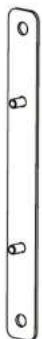
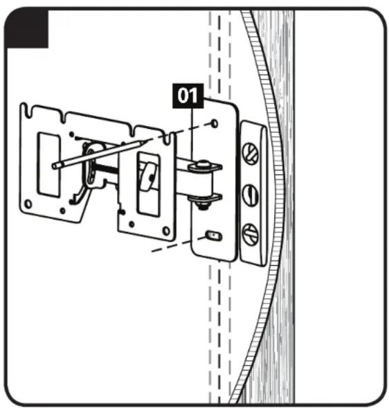
TV Interface Bracket/Wall Plate Assembly
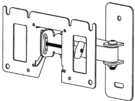
natural_image
Technical line drawing of a mechanical assembly with mounting brackets and a central shaft (no text or symbols)01 x1
Lag Bolts
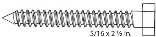
02 x2
Parts and Hardware for STEP 2
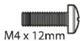
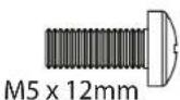
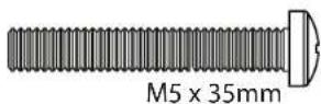
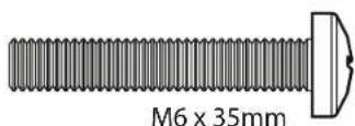
03 x4
TV Screws

06 x4
04 x4
07 x4

05 x4
08 x4
Washers

M4/M5M6
09 x4 x4


Spacers
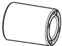
11 x4
Extender Brackets* Extender Bracket Nuts*

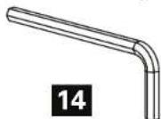
13 x4
12 x2
*Only needed for TVs with 200x200 mm (7 7/8 x 7 7/8 in.) hole patterns
Additional Hardware
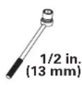
7/32 in. Hex Key
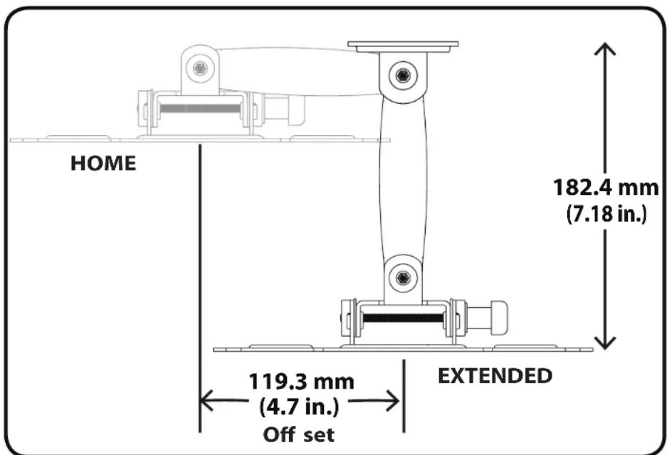
Before You Begin - Consider TV Location and Offset

IMPORTANT: When choosing a location for your TV on the wall, please keep in mind that the TV will shift 119.3 mm (4.7 in.) from the EXTENDED to the HOME positions.
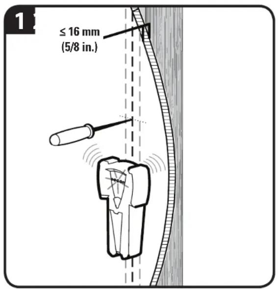
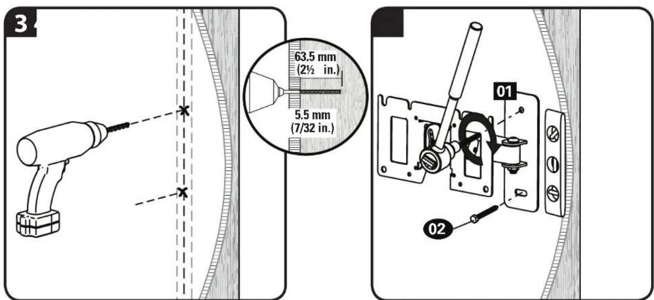
STEP 1 Attach Wall Plate to Wall - Wood Stud ONLY!
- Locate your stud. Verify the center of the stud using an awl, a thin nail, or an edge to edge stud finder.
CAUTION: Avoid potential personal injuries and property damage!
- Drywall covering the wall must not exceed 16 mm (5/8 in.).
● Minimum wood stud size: common 51 x 102 mm (2 x 4 in.) nominal 38 x 89 mm (1½ x 3½ in.).
2. Level the wall plate 01 and mark the hole locations.
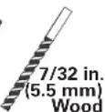
- Drill pilot holes.
IMPORTANT: Pilot holes must be drilled to a depth of 63.5 mm (2½ in.), using a 5.5 mm (7/32 in.) diameter drill bit.
- Tighten the lag bolts 02 only until they are pulled firmly against the wall plate 01.
CAUTION: Improper use could reduce the holding power of the lag bolt. DO NOT over-tighten the lag bolts.
STEP 2 Attach TV Bracket to TV
SELECT TV HARDWARE
- Hand thread screws into the threaded inserts on the back of your TV to determine the correct screw diameter (M4, M5, or M6).
-
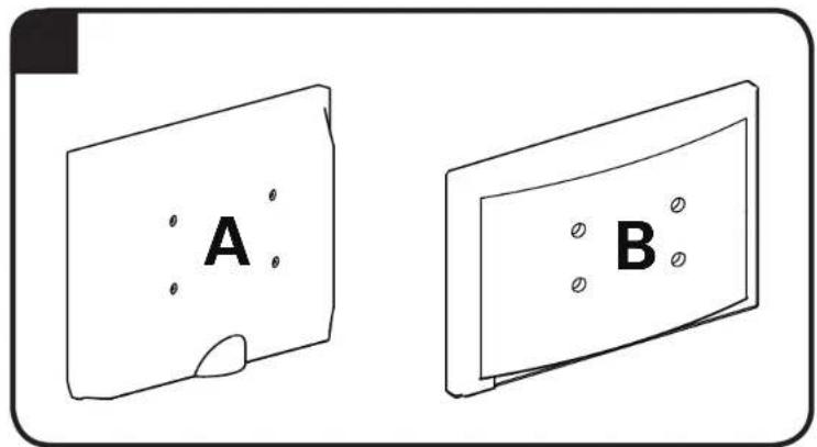
Determine what kind of TV you have and if you require extra space between the wall and the TV to accommodate cables.
-
If you have a flat back TV and do not require extra space for cables, see STEP 2-A
- If you have an irregular back TV or need extra space to accommodate cables, see STEP 2-B
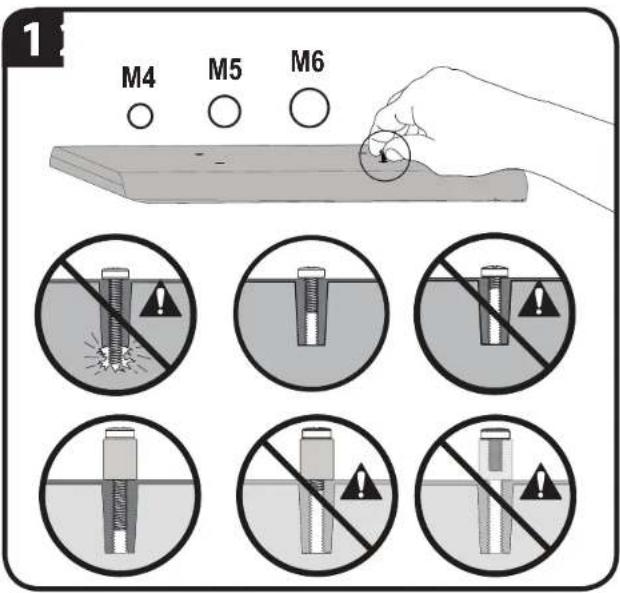
CAUTION: Avoid potential personal injuries and property damage! Verify that there are adequate threads to secure the brackets to the monitor. If you encounter resistance, stop immediately and contact customer service. Use the shortest screw and spacer combination to accommodate your needs. Using hardware that is too long may damage your TV.

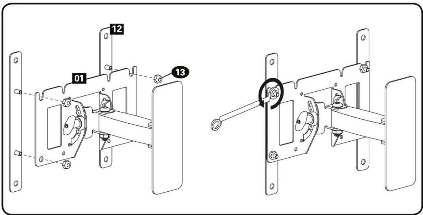
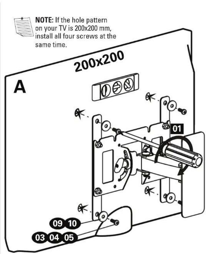
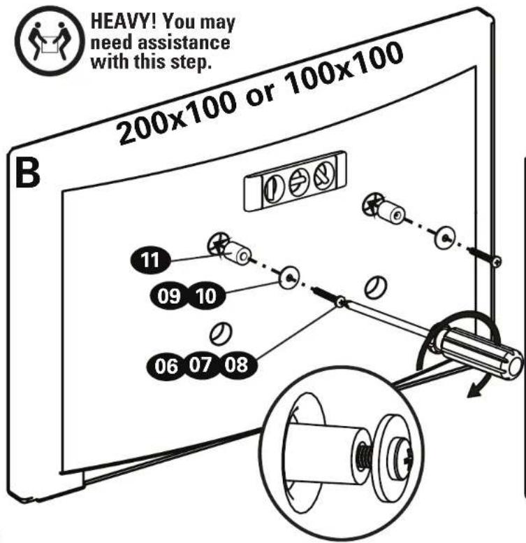
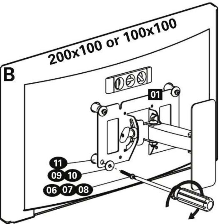
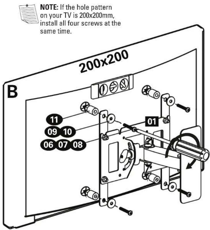
IMPORTANT: If the hole pattern on your TV is 200x200 mm (7 7/8 x 7 7/8 in.) install the extender brackets 12 using the nuts 13 provided.
If your TV hole pattern is less than 200x200 mm do not install the extender brackets. Skip ahead to STEP 2-A or 2-B.
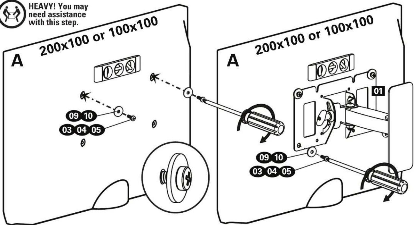
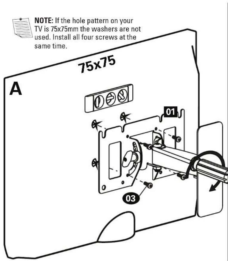
STEP 2A
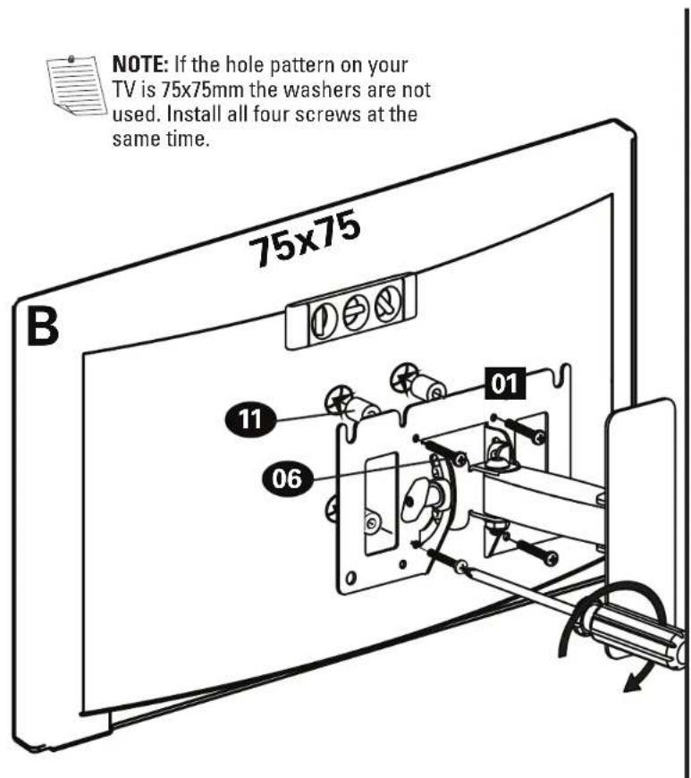
Install the top two screws but do not fully tighten. Leave a small gap so you can slide the TV bracket into place and then install the bottom two screws. Ensure that your bracket is level on the back of the TV. If you need extra space to accommodate cables, recesses, or protrusions; use spacers (see the irregular back option in STEP 2-B).

HEAVY! You may need assistance with this step.
STEP 2B
Install the top two screws but do not fully tighten. Leave a small gap so you can slide the TV bracket into place and then install the bottom two screws. Ensure that your bracket is level on the back of the TV. Standard configurations are shown. For special applications, or if you are unsure about your hardware selection, contact Customer Service.
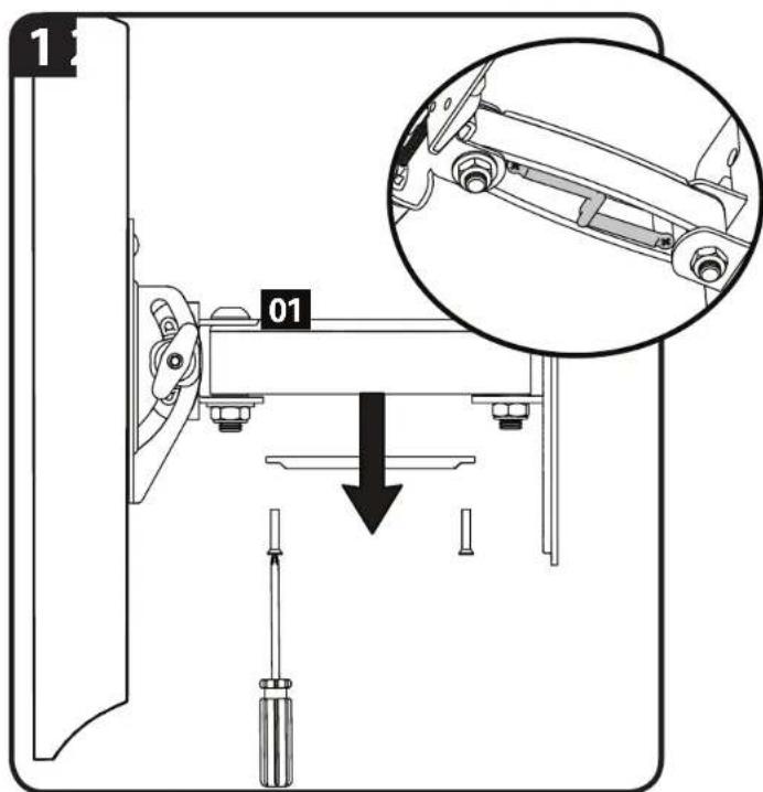
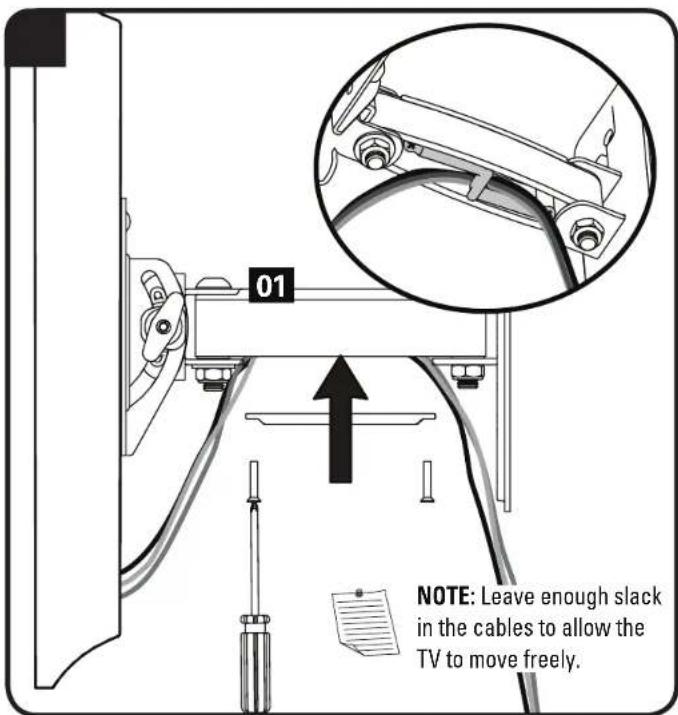
Manage Cables
Troubleshooting
ADJUSTING TENSIONS REMOVING THE TV
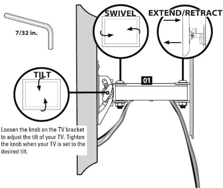
If you need to remove your TV, disconnect all cables and then reverse the procedures in STEP 2A /2B.
ESPAÑOL
Thank you for choosing Sanus Classic! Please take a moment to let us know how we did:

Call us: 1-800-359-5520
UK: 0800 056 2853

Email us: info@sanus.com Let me a review: sanus.com

Find us on Facebook: SANUS Follow up on Twitter @sanussystems
Milestone AV Technologies and its affiliated corporations and subsidiaries (collectively, "Milestone"), intend to make this manual accurate and complete. However, Milestone makes no claim that the information contained herein covers all details, conditions, or variations. Nor does it provide for every possible contingency in connection with the installation or use of this product. The information contained in this document is subject to change without notice or obligation of any kind. Milestone makes no representation of warranty, expressed or implied, regarding the information contained herein. Milestone assumes no responsibility for accuracy, completeness or sufficiency of the information contained in this document.
©2014 Milestone AV Technologies. All rights reserved. Sanus is a division of Milestone.
All other brand names or marks are used for identification purposes and are trademarks of their respective owners.
SANUS • 6436 City West Parkway • Eden Prairie, MN 55344 USA 6901-002343 00