VXF730-B2 - Wall mount SANUS - Free user manual and instructions
Find the device manual for free VXF730-B2 SANUS in PDF.

User questions about VXF730-B2 SANUS
0 question about this device. Answer the ones you know or ask your own.
Ask a new question about this device
Download the instructions for your Wall mount in PDF format for free! Find your manual VXF730-B2 - SANUS and take your electronic device back in hand. On this page are published all the documents necessary for the use of your device. VXF730-B2 by SANUS.
USER MANUAL VXF730-B2 SANUS
natural_image
Technical line drawing of a mechanical assembly with no visible text or symbolsVXF730-B2
INSTRUCTION MANUAL
GET IT RIGHT
THE FIRST TIME
Follow this step-by-step instruction manual to speed up your installation.
WE'RE HERE TO HELP
natural_image
Person holding a play button with a triangular play symbol, standing on a dark surface (no text or symbols visible)Want to watch a video that shows how easy this DIY project will be?

Watch it now at: SANUS.com/2816

text_image
Recommended placementGet it right the first time. HeightFinder™ shows you where to drill.

Check it out at: SANUS.com/2567

natural_image
Two men in a modern office environment, one wearing headset, with blurred background figures (no visible text or symbols)Our install experts are standing by to help.

Call us at:
US: 800-359-5520
EMEA: +31 (0) 495 580 852
UK: 0800 056 2853
AUS: +61 (0) 7 3299 7000
IMPORTANT SAFETY INSTRUCTIONS
PLEASE READ ENTIRE MANUAL PRIOR TO USE – SAVE THESE INSTRUCTIONS
Please read through these instructions completely to be sure you're comfortable with this easy install process.
Check your TV owner's manual to see if there are any special requirements for mounting your TV.
If you do not understand these instructions or have doubts about the safety of the installation, assembly or use of this product, contact Customer Service.

CAUTION: Avoid potential personal injuries and property damage!
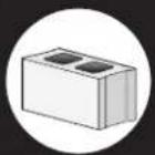
- This product is designed ONLY to be installed into wood studs, solid concrete or concrete block.
— DO NOT INSTALL INTO DRYWALL ALONE — DRYWALL ALONE WILL NOT HOLD THE WEIGHT OF YOUR TV.
• This product is designed for INDOOR USE ONLY. - The wall must be capable of supporting five times the weight of the TV and mount combined.
- Do not use this product for any purpose not explicitly specified by manufacturer.
● Manufacturer is not responsible for damage or injury caused by incorrect assembly or use.
TV Weight Limit
(including accessories)
DO NOT EXCEED

text_image
175 lbs. (79.3 kg)If your TV, plus accessories, weighs MORE than indicated, this mount is NOT compatible.
Visit SANUS.com or call customer service to find a compatible mount.
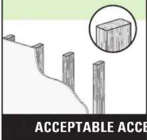
Wall Construction
ONLY install on these acceptable wall types.

Unsure
Call Customer Service

CAUTION:
DO NOT install in drywall alone
Drywall alone will NOT hold the weight of your TV.

wood studs
text_image
ACCEPTABLE ACCEPTSolid concrete or concrete block
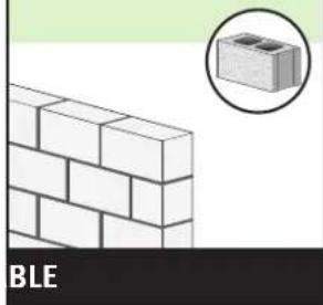
natural_image
Illustration of a brick wall with a magnified inset showing a small block (no text or symbols)Tools Needed
Measure
Pencil Level Tape

ScrewdriverTape
Electric Drill
Socket Wrench

Stud Finder
Awl

Drill Bit

三

Drill Bit

Hammer
DIMENSIONS IN. [MM]
TV INTERFACE
![SANUS VXF730-B2 - DIMENSIONS IN. [MM] - 1](/content/2026/04/694714/images/508169ae8ea265ffe19723bef25aa88226a2347168368d188e359b205b0bf00f.jpg)
text_image
23.62in MAX [600mm] 15.75in [400mm] MAX 7.87in [200mm] MIN 7.87in MIN [200mm]3-D
![SANUS VXF730-B2 - DIMENSIONS IN. [MM] - 2](/content/2026/04/694714/images/8c6dfe0322b718957ff6807f479361a64b90ae0cbc5258d367e68b7efb74e926.jpg)
natural_image
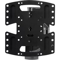
Technical line drawing of a mechanical frame assembly (no text or symbols)WALL PLATE
![SANUS VXF730-B2 - DIMENSIONS IN. [MM] - 3](/content/2026/04/694714/images/10549fb264ed607796df83ad4b9d2c3e421f0424387326d7138bde1bc1984fc8.jpg)
text_image
21.83in [554.6mm] 36.53in [927.7mm] 18.75in [476.2mm] 15.76in [400.4mm] 2.36in [60mm] 12.95in [320mm] 23.26in [590.8mm] 24.00in [609.6mm] 16.00in [406.4mm] 0.36in [9.1mm]TOP VIEW - EXTENDED
![SANUS VXF730-B2 - DIMENSIONS IN. [MM] - 4](/content/2026/04/694714/images/567bce40c2ceeda51aa75b0fda45b98d4c9e76c5c50649d962434a0a3d562fd2.jpg)
text_image
55deg SIMULATED 75° FLAT SCREEN TVSIDE VIEW - EXTENDED
![SANUS VXF730-B2 - DIMENSIONS IN. [MM] - 5](/content/2026/04/694714/images/574a6f92921db2acaf16bad1b0506edfe1c5fa9f5b9553702ce749844240921c.jpg)
text_image
15deg DOWN 5deg UP 30.31in [769.9mm]FULLY ASSEMBLED MOUNT
![SANUS VXF730-B2 - DIMENSIONS IN. [MM] - 6](/content/2026/04/694714/images/0e2b8cce579617e332a7be593a8c58fe74de47ef01f5e088c115a7b87eb9e541.jpg)
text_image
36.71in (934.1mm) 22.03in [558.6mm]TOP VIEW - RETRACTED
![SANUS VXF730-B2 - DIMENSIONS IN. [MM] - 7](/content/2026/04/694714/images/7b4281e9d42c25118dd77989ed4f331d925f4959b79535dc65ac87ed53228a8a.jpg)
SIDE VIEW RETRACTED
![SANUS VXF730-B2 - DIMENSIONS IN. [MM] - 8](/content/2026/04/694714/images/3eae6d7767c10ce8cc3ae48e094e24a086edf8481c74678ac9abfc3b2e34e07d.jpg)
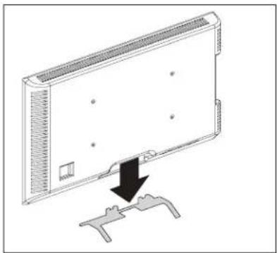
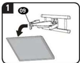
BEFORE YOU BEGIN
Remove the stand from your TV — if attached.
Install any accessories you may have purchased, if they require TV removal prior to assembly. Note that the TV is removable for future accessory purchases.
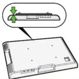
Protect the face of your TV when laying it down for installation.
natural_image
Diagram of a flat-screen monitor with a downward arrow indicating compression or disassembly (no text or symbols present)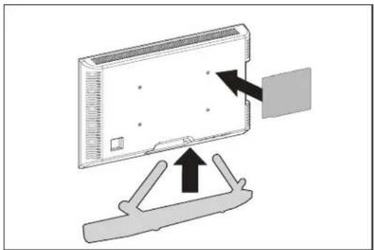
natural_image
Diagram showing a device with an open screen mounted on a stand, with arrows indicating direction of movement (no text or symbols present)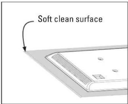
text_image
Soft clean surfaceLegrand AV Inc. and its affiliated corporations and subsidiaries (collectively, "Legrand"), intend to make this manual accurate and complete. However, Legrand makes no claim that the information contained herein covers all details, conditions, or variations. Nor does it provide for every possible contingency in connection with the installation or use of this product. The information contained in this document is subject to change without notice or obligation of any kind. Legrand makes no representation of warranty, expressed or implied, regarding the information contained herein. Legrand assumes no responsibility for accuracy, completeness or sufficiency of the information contained in this document.
ATTACH TV BRACKET TO TVSTEP 1
Parts and Hardware for STEP 1

WARNING:
This product contains small items that could be a choking hazard if swallowed. Before starting assembly, verify all parts are included
and undamaged. If any parts are missing or damaged, do not return the damaged item to your dealer; contact Customer Service. Never use damaged parts!

NOTE:
Not all hardware included will be used.

TV Screws
[Only one size fits your TV]
M6
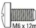
M8
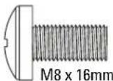
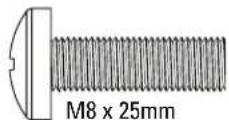
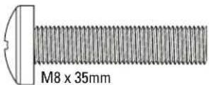
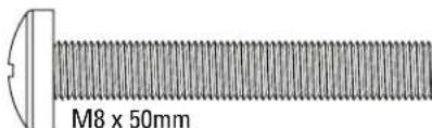
text_image
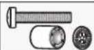
M8 x 50mmWashers
(qty. 4 each)

M6/M8 M6/M8
Spacers
[If necessary] (qty. 4 each)


2.5mm
TV Bracket
04(qty.1)
text_image
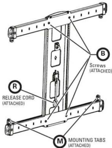
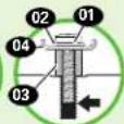
R RELEASE CORD (ATTACHED) M Mounting TABS (ATTACHED) B Screws (ATTACHED)1.1 Select TV Screw Diameter
Only one screw size fits your TV.
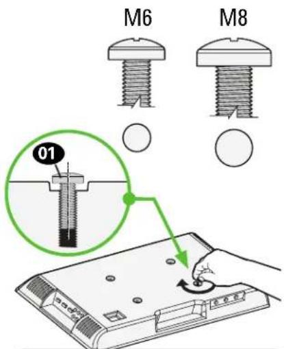
text_image
M6 M8 01
NOTE: If your TV
included inset spacers or adapters, use them UNDER the mount hardware.
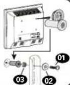
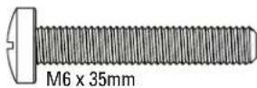
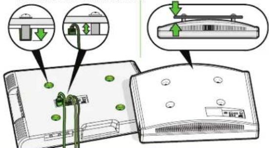
1.2 Select TV Screw Length / Spacers

NO SPACER SPACER

DED
- Flat Back TV
[TV brackets lay flat on your TV]

- Flat Back TV with Extra Space Needed [for deep inset holes or cable interference]
• Rounded or Irregular Back TV [TV brackets NOT resting flat on your TV]
Use long TV screws 01 and spacers 03 to create extra space between the TV and TV bracket.
natural_image
Diagram of a device with a green arrow pointing to a component, showing no text or symbols.Inset Holes Cables Rounded Back
text_image
Diagram showing device connection with green arrows indicating cable or cable movement, alongside a close-up of the device's internal structure.CAUTION: Verify adequate thread engagement with your screw 01, washer 02, spacer 03 combination AND TV bracket 04.
— Too short will not hold your TV. — Too long will damage your TV.
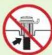
Too Short
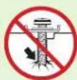
Too Long
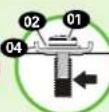
Correct
1.3 Attach TV Bracket Assembly to TV
text_image
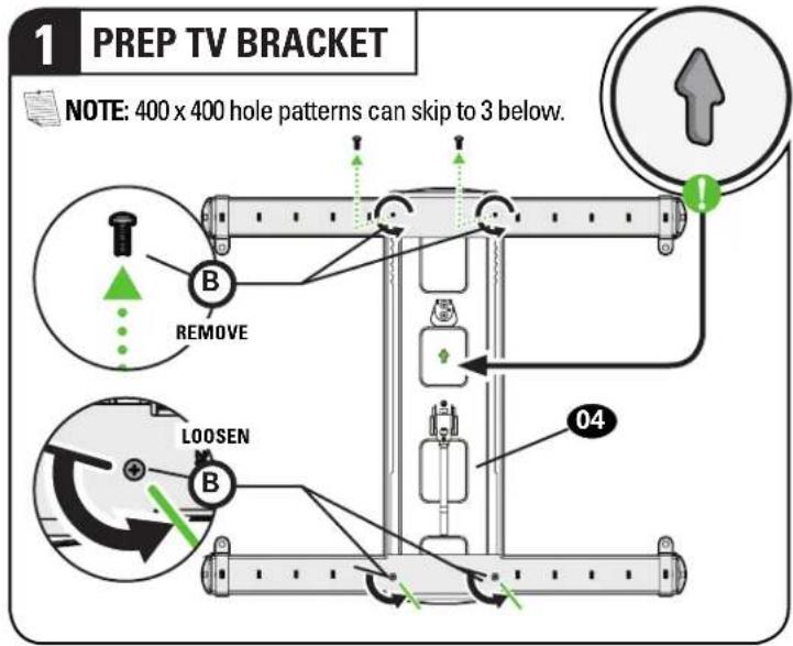
1 PREP TV BRACKET NOTE: 400 x 400 hole patterns can skip to 3 below. B REMOVE LOOSEN B 04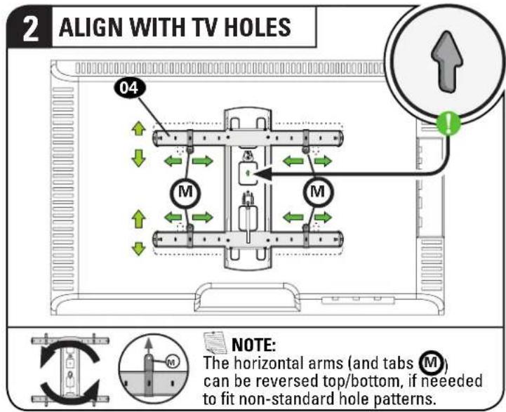
text_image
2 ALIGN WITH TV HOLES 04 M M NOTE: The horizontal arms (and tabs M) can be reversed top/bottom, if needed to fit non-standard hole patterns.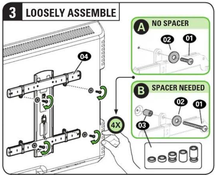
text_image
3 LOOSELY ASSEMBLE A NO SPACER 02 01 B SPACER NEEDED 03 4X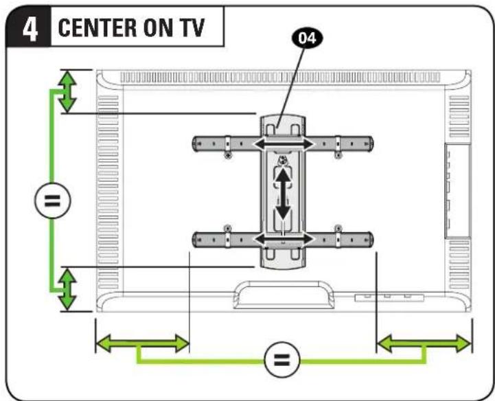
text_image
4 CENTER ON TV 04 =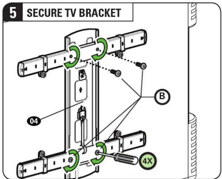
text_image
5 SECURE TV BRACKET 04 B 4X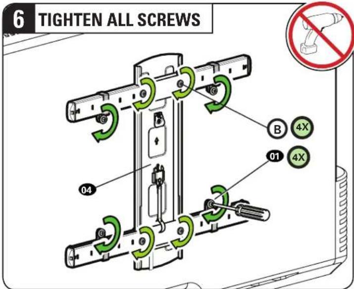
text_image
6 TIGHTEN ALL SCREWS B 4X 01 4X 04STEP 2
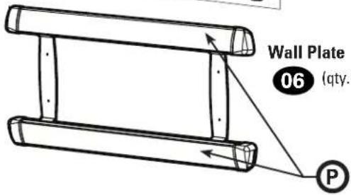
ATTACH WALL PLATE TO WALL
Parts and Hardware for STEP 2

Before starting assembly, verify all parts are included and undamaged. If any parts are missing or damaged, do not return the damaged item to your dealer; contact Customer Service. Never use damaged parts!
natural_image
Simple black-and-white line drawing of a rectangular frame with dashed lines (no text or symbols)Wall Plate
Template
05 (qty. 1)
text_image
Wall Plate 06 (qty. PCover Plate (Attached)
text_image
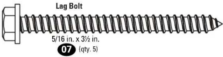
Lag Bolt 5/16 in. x 3½ in. 07 (qty. 5)For concrete installations ONLY

CAUTION: Do not use in drywall or wood Concrete Anchor

text_image
08 (qty. 5) Fischer UX10 x 60R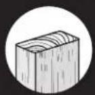
For WOOD STUD INSTALLATIONS
Follow 2A on PAGE 7.
For CONCRETE INSTALLATIONS
Follow 2B on PAGE 8.
2A
Wood Stud Installation
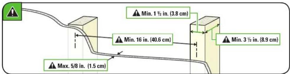
CAUTION: Avoid potential personal injury or property damage!
- Drywall covering the wall must not exceed 5/8 in. (1.5 cm)
• Minimum wood stud size: nominal 2 x 4 in. (5.1 x 10.2 cm) actual 1 ½ x 3 ½ in. (3.8 x 8.9 cm)
• Minimum horizontal space between fasteners:16 in. (40.6 cm)
• Stud centers must be verified
text_image
Min. 1 ½ in. (3.8 cm) Min. 16 in. (40.6 cm) Min. 3 ½ in. (8.9 cm) Max. 5/8 in. (1.5 cm)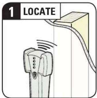
text_image
1 LOCATE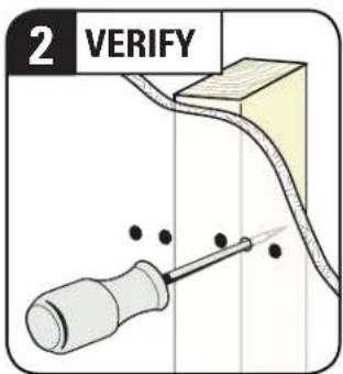
text_image
2 VERIFY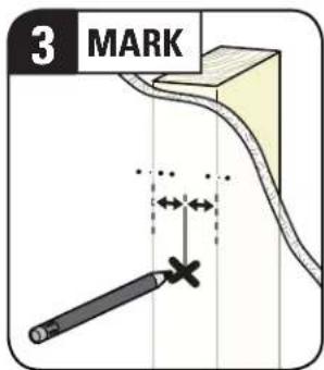
text_image
3 MARK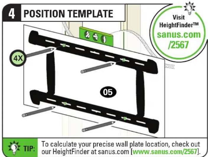
text_image
4 POSITION TEMPLATE Visit HeightFinder™ sanus.com /2567 4X 05 TIP: To calculate your precise wall plate location, check out our HeightFinder at sanus.com [www.sanus.com/2567].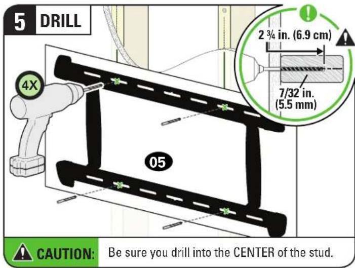
text_image
5 DRILL 4X 2 3/4 in. (6.9 cm) 7/32 in. (5.5 mm) 05 CAUTION: Be sure you drill into the CENTER of the stud.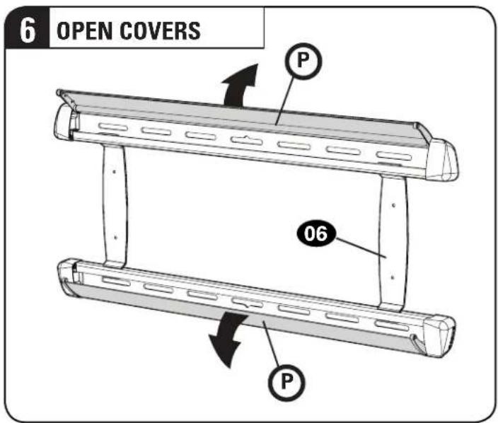
text_image
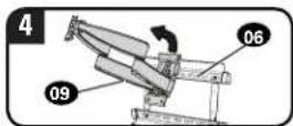
6 OPEN COVERS P 06 P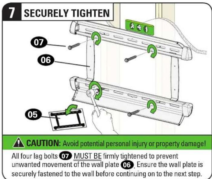
text_image
7 SECURELY TIGHTEN 07 06 05 CAUTION: Avoid potential personal injury or property damage! All four lag bolts 07 MUST BE firmly tightened to prevent unwanted movement of the wall plate 06. Ensure the wall plate is securely fastened to the wall before continuing on to the next step.2B
Solid Concrete or Concrete Block Installation
CAUTION: Avoid potential personal injury or property damage!
- Mount the wall plate 06 directly onto the concrete surface
• Minimum solid concrete thickness: 8 in. (20.3 cm)
• Minimum concrete block size: 8 x 8 x 16 in. (20.3 x 20.3 x 40.6 cm) - Minimum horizontal space between fasteners: TOP RAIL: 12 in. (30.5 cm) BOTTOM RAIL: 24 in. (61.0 cm)
- FOR CONCRETE APPLICATIONS, TV bracket 09 must remain centered in wall plate 06. Keep this in mind when selecting the wall plate location
text_image
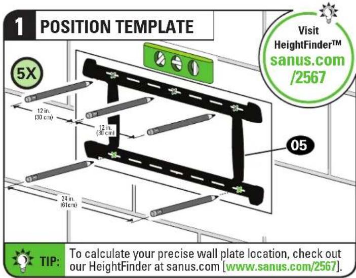
1 POSITION TEMPLATE 5X 12 in. (30 cm) 12 in. (30 cm) 24 in. (61 cm) 05 Visit HeightFinder™ sanus.com /2567 TIP: To calculate your precise wall plate location, check out our HeightFinder at sanus.com [www.sanus.com/2567].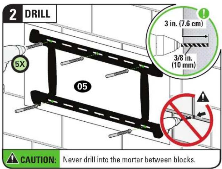
text_image
2 DRILL 5X 05 3 in. (7.6 cm) 3/8 in. (10 mm) CAUTION: Never drill into the mortar between blocks.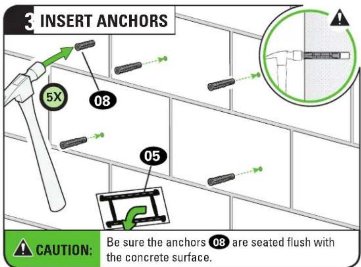
text_image
INSERT ANCHORS 5X 08 05 CAUTION: Be sure the anchors 08 are seated flush with the concrete surface.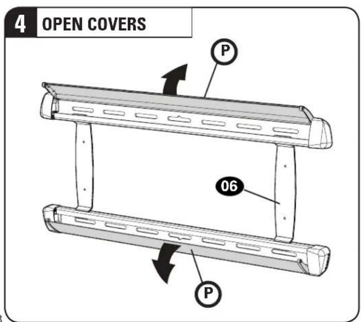
text_image
4 OPEN COVERS P 06 P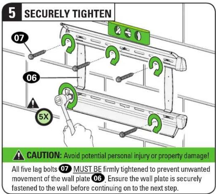
text_image
5 SECURELY TIGHTEN 07 06 5X CAUTION: Avoid potential personal injury or property damage! All five lag bolts 07 MUST BE firmly tightened to prevent unwanted movement of the wall plate 06. Ensure the wall plate is securely fastened to the wall before continuing on to the next step.Parts and Hardware for STEP 3

WARNING:
This product contains small items that could be a choking hazard if swallowed. Before starting assembly, verify all parts are included any parts are missing or damaged, do not return the damaged item to your dealer; contact Customer Service. Never use damaged par
text_image
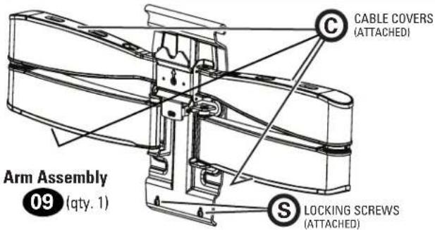
CABLE COVERS (ATTACHED) Arm Assembly 09 (qty. 1) LOCKING SCREWS (ATTACHED)
10-32 x 3/8 in.
Securement Screw
10(qty.1)
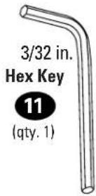
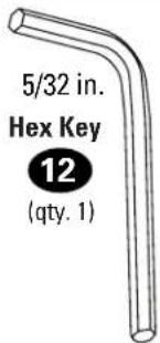
text_image
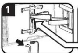
5/32 in. Hex Key 12 (qty. 1)3.1 Attach the Arm Assembly to the Wall Plate

HANG

HEAVY! You may need assistance with this step.
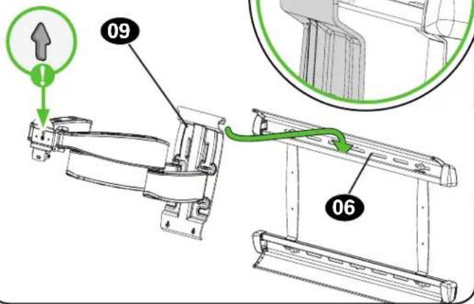
text_image
09 06
text_image
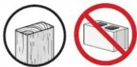
Two safety symbols: a wooden block inside a circle and a prohibition sign with a red circle.
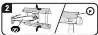
CAUTION: Avoid potential personal injury or property damage!
For CONCRETE APPLICATIONS:
The arm assembly 09 MUST remain centered in wall plate 06
text_image
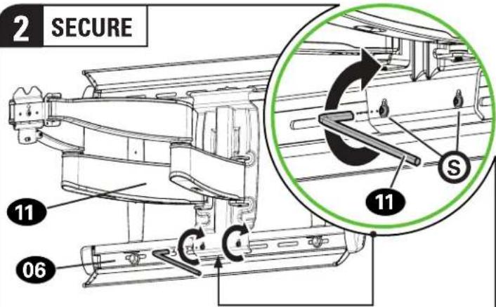
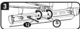
2 SECURE 11 06 C C S 11
CAUTION: Avoid potential personal injury or property damage!
Always make sure both locking screws S are tightened, so the arm assembly 09 is securely fastened to wall plate 06.

CLOSE COVERS
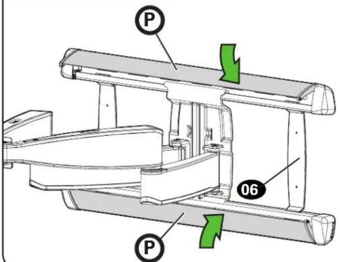
text_image
P 06 P3.2 Hang TV onto Arm Assembly
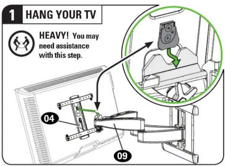
text_image
1 HANG YOUR TV HEAVY! You may need assistance with this step. 04 09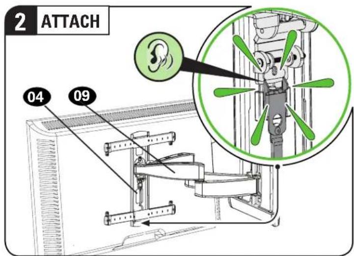
text_image
2 ATTACH 04 09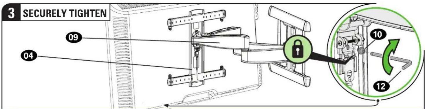
text_image
3 SECURELY TIGHTEN 09 04 10 12CAUTION: Avoid potential personal injury or property damage!
Always make sure your securement screw 10 is tightened, so the TV is securely fastened to the arm assembly 09.
MANAGE CABLES
text_image
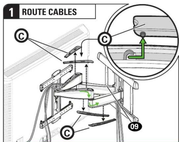
1 ROUTE CABLES C C 09IMPORTANT:
Pull arm 09 to its full extension, to leave enough slack and prevent stretching the cables when the arms are moved.
text_image
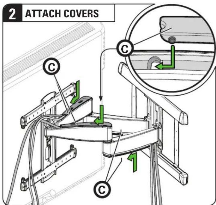
2 ATTACH COVERS C CADJUSTMENTS
LEVEL
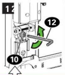
text_image
12 12 10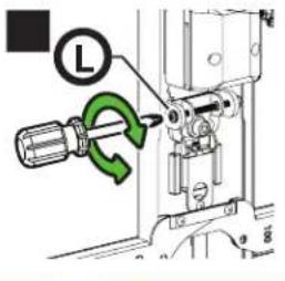
text_image
L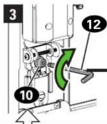
text_image
3 10 12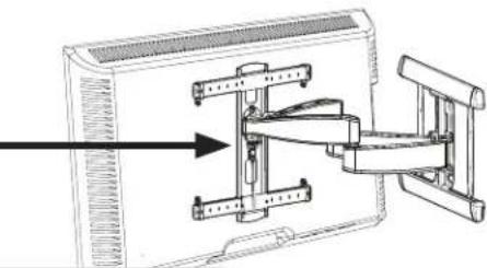
natural_image
Technical line drawing of a mechanical assembly with no visible text or symbolsCAUTION:
Screw 10 MUST be loosened before turning screw L.
CAUTION: Avoid potential personal injury or property damage! Always make sure your securement screw 10 is tightened, so the TV is securely fastened to the arm assembly 09.
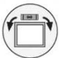
TILT
Your TV should adjust easily when moved, then stay in place.
Adjust the tilt tension knob T if your TV naturally tilts up or down.
NOTE: If you do not intend to adjust the tilt for different viewing locations, you can tighten the tilt tension knobs Ⓣ to prevent unwanted movement.
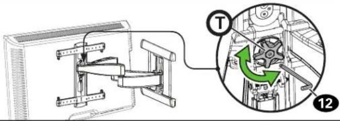
text_image
Technical diagram showing mechanical assembly with labeled component 'T' and numbered parts 12 and 13
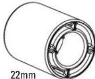
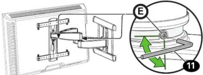
EXTEND/RETRACT
ONLY IF NEEDED, adjust the extension/retraction arm
tension with screw E using hex key 11.
CAUTION: Avoid potential personal injury or property damage! DO NOT remove screws Ⓔ, only turn enough for slight adjustment.
text_image
Technical diagram showing mechanical assembly with labeled components and directional arrows, including a magnified inset of a cylindrical component.
SIDE-TO-SIDE SHIFT

HEAVY! You may need assistance with this step.
CAUTION: Avoid potential injuries or property damage! Do NOT adjust the arm position from center for concrete applications. Arm 09 MUST remain centered in wall plate 06 for all concrete applications!
For wood stud applications ONLY:
- Remove the TV (See below).
- Open cover plates Ⓟ
- Loosen but do not remove, locking screws
- Slide arm 09 to the desired position.
- Tighten locking screws Ⓢ
CAUTION: Always make sure both locking screws S are tightened so the TV is securely fastened to wall plate 06.
- Close the cover plates Ⓟ, then hang your TV (see STEP 3).
text_image
1 09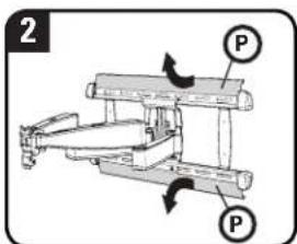
text_image
2 P P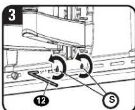
text_image
3 12 S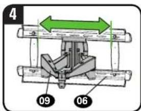
text_image
4 09 06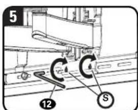
text_image
5 12 C 4 S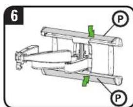
text_image
6 P P
REMOVING THE TV

HEAVY! You may need assistance with this step.
text_image
1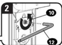
text_image
2 10 12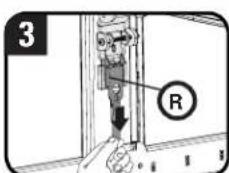
text_image
3 R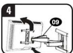
text_image
4 09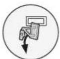
REMOVING THE ARM

HEAVY! You may need assistance with this step.
Español
natural_image
Illustration of five different electrical components: a tape measure, rolled cable, pushpin, three buttons, and screwdriver (no text or symbols present)
text_image
Massive Betonlnatural_image
Illustration of five different tools and components: a tape measure, roller, screwdriver, and plus button (no text or symbols present)(1) AD = BD = 1
Klebeband
[Non-Text]
Wasserwaage

Elektrobohrer
The Ground Truth image displays a single, solid horizontal line. According to Rule 2 (UNDERSCORE & LINE RULES), this is a stylistic or background line, not a placeholder underscore. Therefore, the OCR result must ignore it and output nothing or only meaningful text. The provided OCR content is "____", which consists of four underscores. This is an incorrect interpretation of the line as a placeholder, violating the rule that stylistic lines must be ignored. The OCR has hallucinated placeholder underscores where none exist in the GT. Hence, the result is inconsistent with the Ground Truth.
text_image
Massive betonbMassief beton of
betonblokken?

Weet u het niet
zeker?
Bel de klantenservice:
[US]: 800-359-5520 [EMEA]: +31 (0) 495 580 852
[UK]: 0800 056 2853 [AUS]: +61 (0) 7 3299 7000
3
Beschikt u over
text_image
Massive betong
Osäker?
Ring kundtjänst:
[US]: 800-359-5520 [EMEA]: +31 (0) 495 580 852 [UK]: 0800 056 2853 [AUS]: +61 (0) 7 3299 7000
text_image
SANUS Product Registration Name - Product Registration Product Registration Regulate your product if only uses 50 minutes. We're got the time at their Step 1 - Login Login with Facebook Login new password Create An Account Create Account Create a SANUS account for registered user products, create a profile, and zoom the benefits of customized SANUS news and updates. Product Registration Steps 1 - Account Creation Steps 2 - Product Information Steps 3 - Registration Companies TALK TO US 1-800-359-5520 Copyright - April 2017 - Open OUT Security - December 2017 - Open OUT WARRANTY informationRegister your new mount to make the most of your SANUS warranty.
Visit SANUS.com to register now— it takes 25 seconds!
natural_image
Modern living room interior with a wooden sofa, large wall mural, and TV set (no visible text or symbols)When you share your handiwork with your friends, tag
sanusspaces
for a chance to be featured on SANUS.com

@sanussystems

SanusSystems

pinterest.com/SANUS

SanusSystems
800-359-5520 • info@sanus.com • SANUS.com SANUS • 6436 City West Parkway • Eden Prairie, MN 55344 USA ©Legrand AV, Inc
6901-602366 00