
VSF716-B2 - Wall mount SANUS - Free user manual and instructions
Find the device manual for free VSF716-B2 SANUS in PDF.

| Product Type | TV wall mount |
| Brand | Sanus |
| Model | VSF716-B2 |
| Maximum supported weight | 15.8 kg (35 lb) |
| Compatible wall types | Wood studs, solid concrete, concrete block |
| Wall material (drywall) | Not compatible for standalone installation |
| Maximum drywall thickness | 1.5 cm (5/8 in) |
| Minimum wood stud size | Nominal 5.1 x 10.2 cm (2 x 4 in) |
| Wall plate dimensions | See manual page 62 |
| Main features | Wall mounting, tilt, extension/retraction, cable management |
| Tilt angle | Adjustable with tension knobs |
| Built-in level | Yes (leveling screws) |
| Maintenance and cleaning | Clean with a soft, dry cloth |
| Safety | Do not install alone on drywall; use screws of appropriate length |
| Spare parts and repairability | Contact customer service for missing or damaged parts |
| General information | Manual available in multiple languages; telephone support available |
| Warranty | See manufacturer's conditions |
| Country of manufacture | Not specified in the manual |
Frequently Asked Questions - VSF716-B2 SANUS
User questions about VSF716-B2 SANUS
0 question about this device. Answer the ones you know or ask your own.
Ask a new question about this device
Download the instructions for your Wall mount in PDF format for free! Find your manual VSF716-B2 - SANUS and take your electronic device back in hand. On this page are published all the documents necessary for the use of your device. VSF716-B2 by SANUS.
USER MANUAL VSF716-B2 SANUS
natural_image
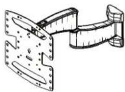
Technical line drawing of a mechanical assembly with mounting flanges and a curved bracket (no text or symbols)VSF716-B2
VSF716-S2
INSTRUCTION MANUAL
GET IT RIGHT
THE FIRST TIME
Follow this step-by-step instruction manual to speed up your installation.
Want to watch a video that shows how easy this DIY project will be?
Watch it now at: SANUS.com/2791
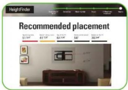
Get it right the first time. HeightFinder™ shows you where to drill.

Check it out at: SANUS.com/2567

natural_image
Two men in a busy office environment, one wearing a headset and the other seated at a computer workstation (no visible text or symbols)Our install experts are standing by to help.
Call us at:
US: 800-359-5520
EMEA: +31 (0) 495 580 852
UK: 0800 056 2853
AUS: +61 (0) 7 3299 7000
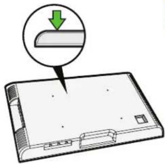
Before you begin
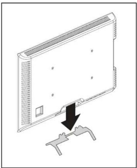
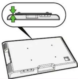
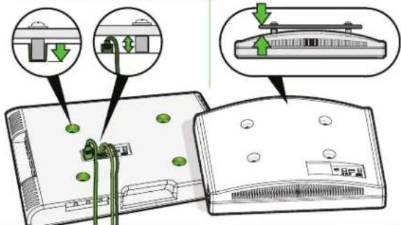
Remove the stand from your TV — if attached.
Install any accessories you may have purchased — if they require the TV to be removed from the wall for assembly. The TV is removable for future accessory purchases.
Protect the face of your TV when laying it down for installation.
natural_image
Diagram of a computer monitor with a black arrow pointing to a handle, showing no text or symbols.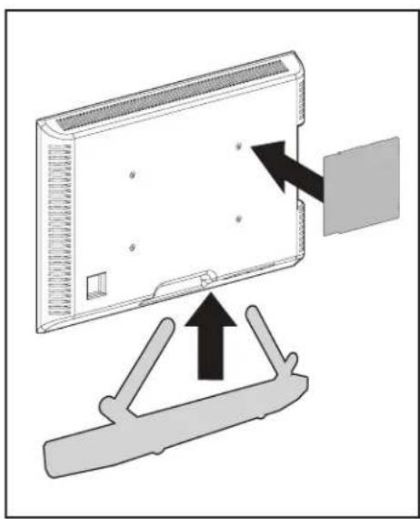
natural_image
Diagram showing a device with an arrow pointing to a panel, mounted on a stand (no text or symbols present)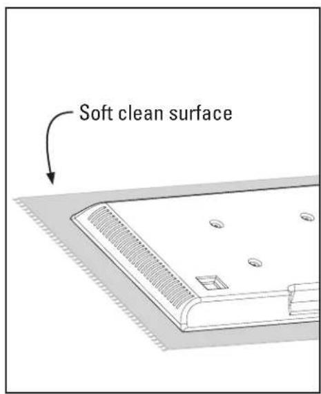
IMPORTANT SAFETY INSTRUCTIONS – PLEASE READ MANUAL PRIOR TO USE – SAVE THESE INSTRUCTIONS
Please read through these instructions completely to be sure you're comfortable with this easy install process.
Check your TV owner's manual to see if there are any special requirements for mounting your TV.
If you do not understand these instructions or have doubts about the safety of the installation, assembly or use of this product,
contact Customer Service: US: 800-359-5520 [EMEA]: +31 (0) 495 580 852 [UK]: 0800 056 2853 [AUS]: +61 (0) 7 3299 7000.

CAUTION: Avoid potential personal injuries and property damage!
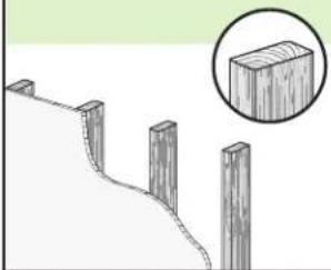
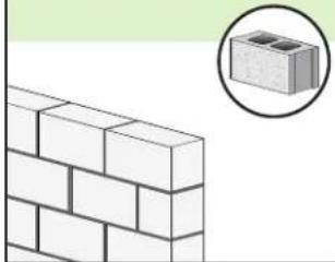
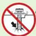
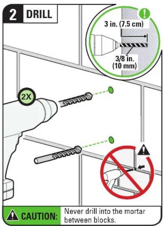
- This product is designed ONLY to be installed into wood studs, solid concrete or concrete block.
— DO NOT INSTALL INTO DRYWALL ALONE — DRYWALL ALONE WILL NOT HOLD THE WEIGHT OF YOUR TV. - This product is designed for INDOOR USE ONLY.
- The wall must be capable of supporting five times the weight of the TV and mount combined.
- Do not use this product for any purpose not explicitly specified by manufacturer.
● Manufacturer is not responsible for damage or injury caused by incorrect assembly or use.
TV Weight Limit
(including accessories)
DO NOT EXCEED
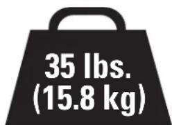
If your TV (including accessories) exceeds this weight, this mount is NOT compatible.
Visit SANUS.com or call customer service to find a compatible mount.
Wall Construction
ONLY install on these acceptable wall types.

Unsure
Call
Customer
Service
[EMEA]: +31 (0) 495 580 852
[UK]: 0800 056 2853
[AUS]: +61 (0) 7 3299 7000

CAUTION:
DO NOT install in drywall alone
Drywall alone will NOT hold the weight of your TV.
wood studs Solid conc
natural_image
Diagram of a wooden fence with four posts and a magnified inset showing a rectangular block (no text or symbols)ACCEPTABLE ACCB
rete or concrete block
natural_image
Illustration of a brick wall with a magnified inset showing a cinder block (no text or symbols)ABLE
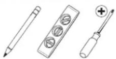
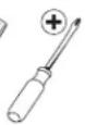
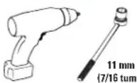
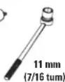
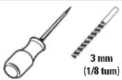
Tools Needed
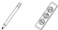
Measure

Pencil Level Tape
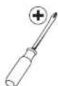
ScrewdriverTape
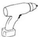
Electric Drill
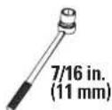
Socket Wrench
Wood Stud Install
Stud Finder
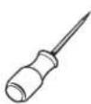
Awl
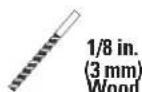
Drill Bit
Concrete Install
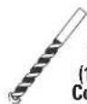
Drill Bit
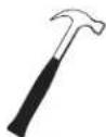
Hammer
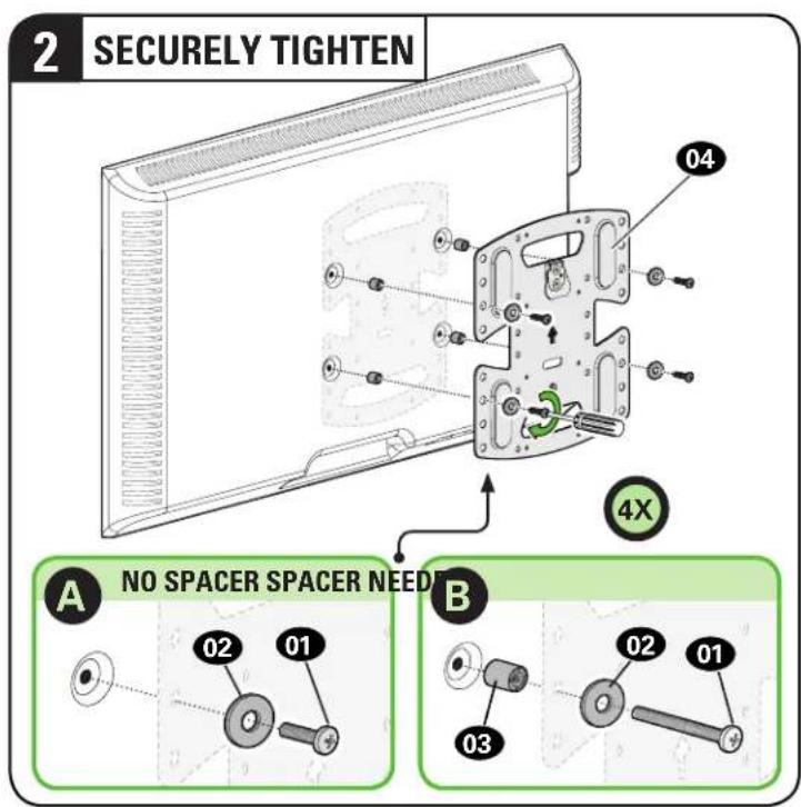
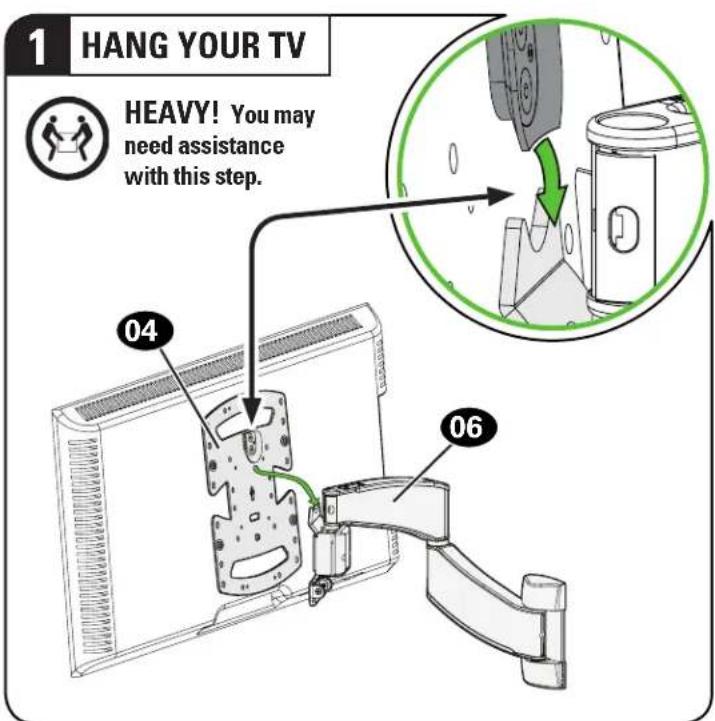
STEP 1
Attach TV Bracket to TV

WARNING:
This product contains small items that could be a choking hazard if swallowed. Before starting assembly, verify all parts are included my parts are missing or damaged, do not return the damaged item to your dealer; contact Customer Service. Never use damaged parts!

NOTE:
Not all hardware included will be used.
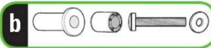
STEP 1 Parts and Hardware

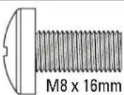
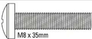
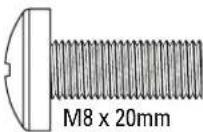
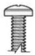
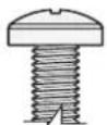
TV Screws
(qty. 4 each) [Only one size fits your TV]
M4
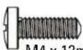
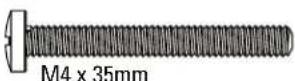
M6
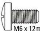
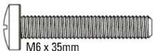
M8
Washers (qty. 4 each

M4
M6/M8
Spacers [If necessary]
(qty. 4 each)

M4/M6/M8
natural_image
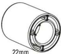
Technical line drawing of a cylindrical mechanical component with 22mm dimension label (no text or symbols beyond the measurement)TV Bracket

(qty. 1)
natural_image
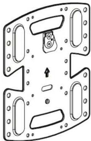
Technical line drawing of a mechanical component with mounting holes and internal features (no text or symbols)Only one screw size fits your TV.
M4
O
M6
O
M8
O

If your TV included
inset spacers or wall mount adapters, see
Troubleshooting on PAGE 21.
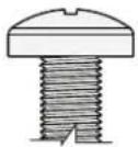
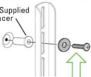
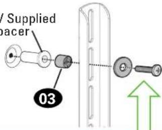
1.2 Select TV Screw Length and Spacers1.1 Select TV Screw Diameter

[TV brackets lay flat on your TV]
Use short TV screws 01
Spacers 03 not needed.

- Flat Back TV with Extra Space Needed
[for deep inset holes or cable interference]
• Rounded or Irregular Back TV
[TV brackets NOT resting flat on your TV]
natural_image
Diagram of a device with a green arrow pointing to a component, showing no text or symbols.Use long TV screws 01 and spacers 03 to create extra space between the TV and TV bracket.
Inset Holes Cables Rounded Back
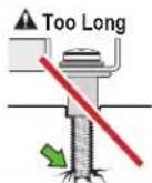
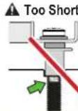
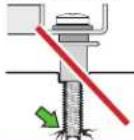
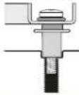
CAUTION: Verify adequate thread engagement with your screw 01, washer 02, spacer 03 combination AND TV bracket 04.
— Too short will not hold your TV.
— Too long will damage your TV.
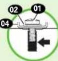
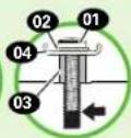
Too Short Too Long Correct
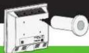
1.3 Attach TV Bracket to Your TV
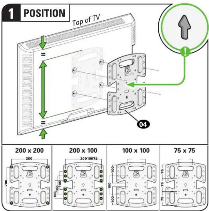
Center TV bracket 04 over your TV hole pattern as shown.
Various hole positions included for non-centered TV hole patterns.
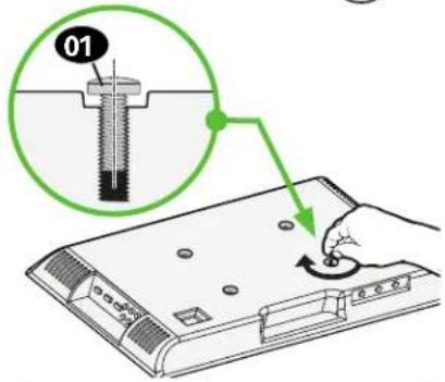
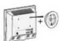
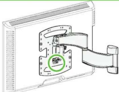
STEP 2
Attach Wall Plate to Wall

WARNING:
This product contains small items that could be a choking hazard if swallowed. Before starting assembly, verify all parts are
included and undamaged. If any parts are missing or damaged, do not return the damaged item to your dealer; contact Customer Service.
Never use damaged parts!

NOTE:
Not all hardware included will be used.
Parts and Hardware for STEP 2
Drill Template

06 x1
Washer
1/4 in.

For concrete installations ONLY

CAUTION:
Do not use in drywall or wood
Concrete Anchor

x2
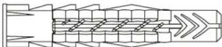
natural_image
Pure mechanical component diagram without any text, numbers, or symbolsFischer UX10 x 60R
STEP 2A Attach Wall Plate

Wood Stud Installation
CAUTION: Avoid potential personal injury or property damage!
- Drywall covering the wall must not exceed 5/8 in. (1.5 cm)
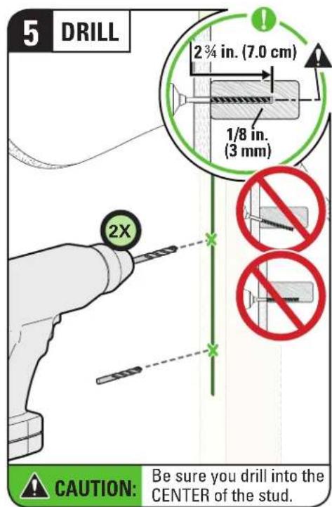
• Minimum wood stud size: nominal 2 x 4 in. (5.1 x 10.2 cm) actual 1 ½ x 3 ½ in. (3.8 x 8.9 cm)
• Stud center must be verified
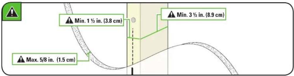
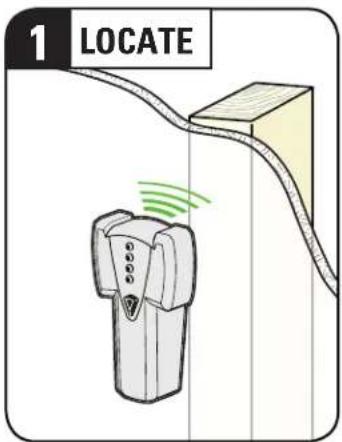
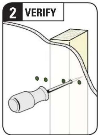
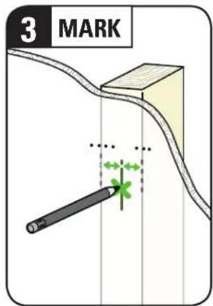
![4 POSITION TEMPLATE 05 2X Visit HeightFinder™ sanus.com /2567 TIP: To calculate your precise wall plate location, check out our HeightFinder at sanus.com [www.sanus.com/2567].](/content/2026/04/694713/images/ab5f1378298a8f1ba15b6480dbf9f1c55e2829266ed386ce9454e5f932c919a9.jpg)

STEP 2A (continued)
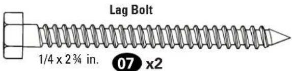
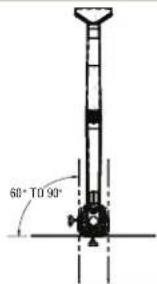
STEP 2B Attach Wall Plate

Solid Concrete or Concrete Block Installation
CAUTION: Avoid potential personal injury or property damage!
- Mount the arm assembly 06 directly onto the concrete surface (no surface covering)
• Minimum solid concrete thickness: 8 in. (20.3 cm)
• Minimum concrete block size: 8 x 8 x 16 in. (20.3 x 20.3 x 40.6 cm)
![1 POSITION TEMPLATE Visit HeightFinder™ sanus.com /2567 05 TIP: To calculate your precise wall plate location, check out our HeightFinder at sanus.com [www.sanus.com/2567].](/content/2026/04/694713/images/8e989a6453441348c2ff524d33a2ac71c4078897ea85f4b7d1d24f7c831db48e.jpg)
STEP 2B (continued)
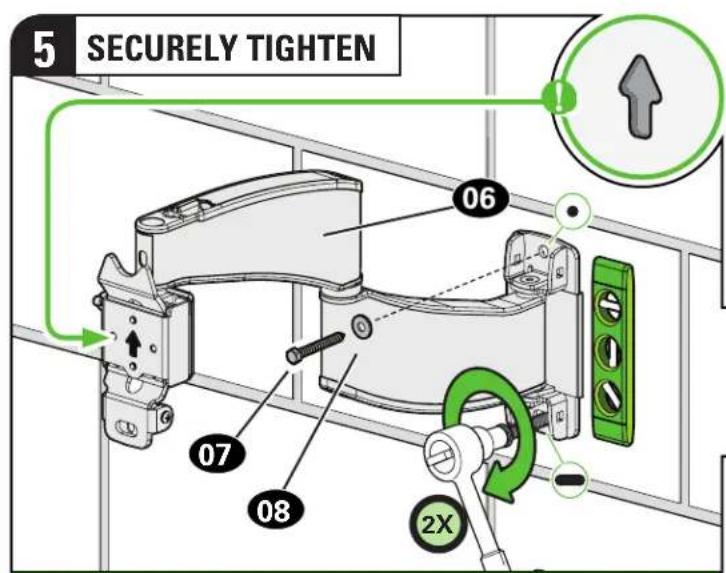

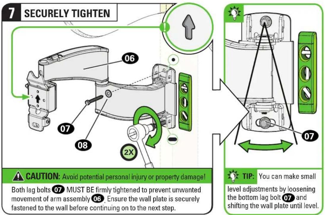
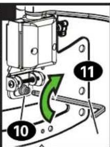
CAUTION: Avoid potential personal injury or property damage!
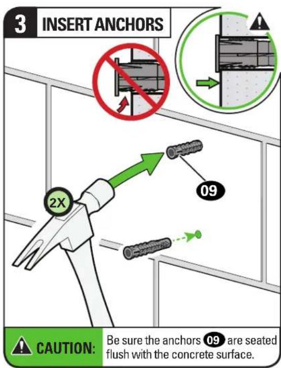
Both lag bolts 07 MUST BE firmly tightened to prevent unwanted movement of arm assembly 06. Ensure the wall plate is securely fastened to the wall before continuing on to the next step.
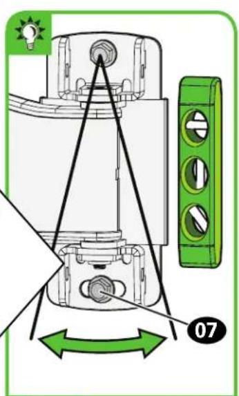

TIP: You can make small
level adjustments by loosening the bottom lag bolt 07 and shifting the wall plate until level.
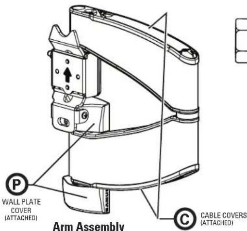
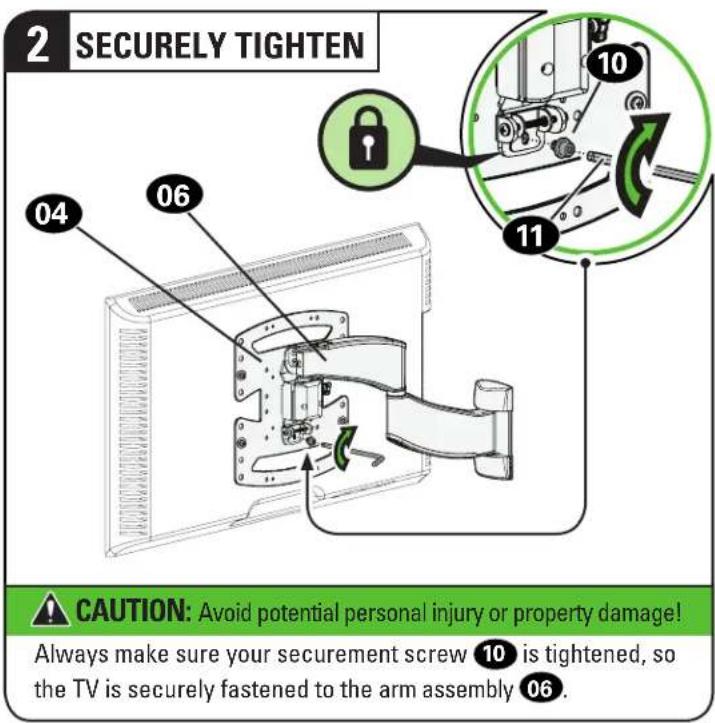
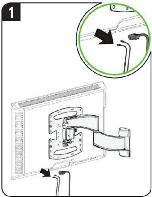
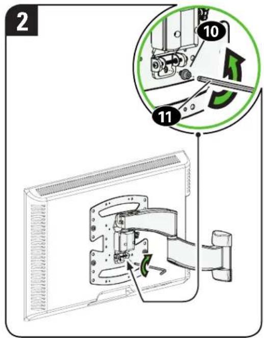
STEP 3
Attach TV to Wall Plate

WARNING:
Before starting assembly, verify this part is undamaged. If damaged, do not return the damaged item to your dealer; contact
Customer Service. Never use damaged parts!
Parts and Hardware for STEP 3
Securement Screw
10-32 x 1/4 in.
10
x1
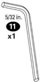
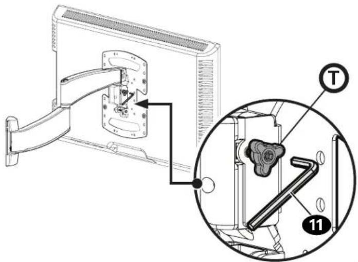
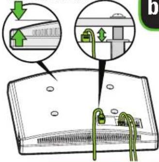
Hex Key
Manage Cables
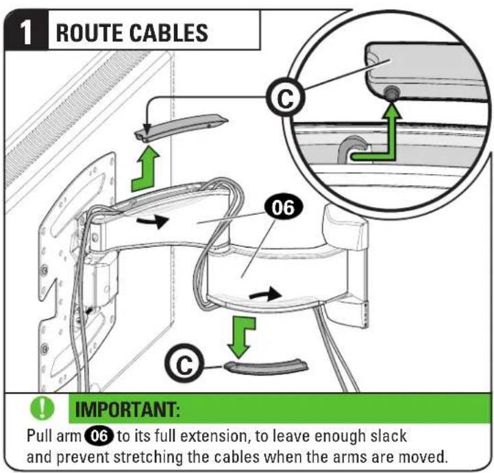
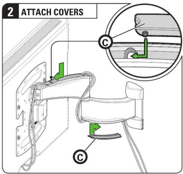
Adjustments
LEVEL ADJUSTMENT TILT ADJUSTMENT
natural_image
Diagram of a computer monitor with a scroll and cable, showing internal components (no text or symbols)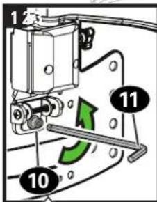
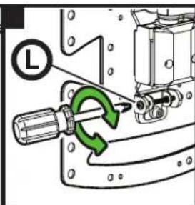
CAUTION:
Screw 10 MUST be loosened before turning screw L.
CAUTION: Injury or pro
Avoid potential personal damage!
Always make sure your securement screw 10 is tightened, so the TV is securely fastened to the arm assembly 11.
Your TV should adjust easily when moved, then stay in place.
Adjust the tilt tension knobs Ⓣ if your TV naturally tilts up or down.

NOTE: If you do not intend to adjust the tilt for different viewing actions, you can tighten the tilt tension knobs (T), to prevent wanted movement. If needed, use hex key to tighten more firmly.
REMOVE THE TV

HEAVY! You may need assistance with this step.

Troubleshooting
TV SUPPLIED SPACERS

Use your TV supplied spacer for:
- Flat Back TV [TV brackets lay flat on your TV]

NOTE: M8 screws can be used without the washer for extra thread engagement.
FLAT BACK
natural_image
Diagram of a device with a green arrow pointing to a component, showing no text or symbols.
TV Supplied Spacer

CAUTION: Avoid potential injury or property damage!
Use the correct screw length for adequate thread engagement.
- Too short will not hold the TV.
- Too long will damage the TV.
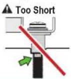
If you are uncertain about your hardware selection, contact Customer Service

Use your TV supplied spacer and spacer 03 for:
• Flat Back TV with Extra Space Needed
[for deep inset holes or cable interference]
• Rounded or Irregular Back TV
[TV brackets NOT resting flat on your TV]
NOTE: M8 screws can be used without the washer for extra thread engagement.
ROUND BACK CABLES
natural_image
Three mechanical components shown in line drawings: a cylindrical cap, a threaded bolt, and a flat pin (no text or symbols)TV Supplied Spacer

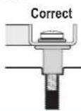
CAUTION: Avoid potential injury or property damage!
Use the correct screw length for adequate thread engagement.
- Too short will not hold the TV.
- Too long will damage the TV.
▲ Too Long
Correct
natural_image
Illustration of five different tools and a power tool, including a remote control, screwdriver, and push-button (no text or symbols present)
Bel de klantenservice: US: 800-359-5520 [EMEA]: +31 (0) 495 580 852 [UK]: 0800 056 2853 [AUS]: +61 (0) 7 3299 7000
Måttband
Penna
Vattenpass
Skruvmejsel
Elborr
Hylsnyckel


Regelsökare
Pryl

Ring kundtjänst:
US: 800-359-5520 [EMEA]: +31 (0) 495 580 852
[UK]: 0800 056 2853 [AUS]: +61 (0) 7 3299 7000
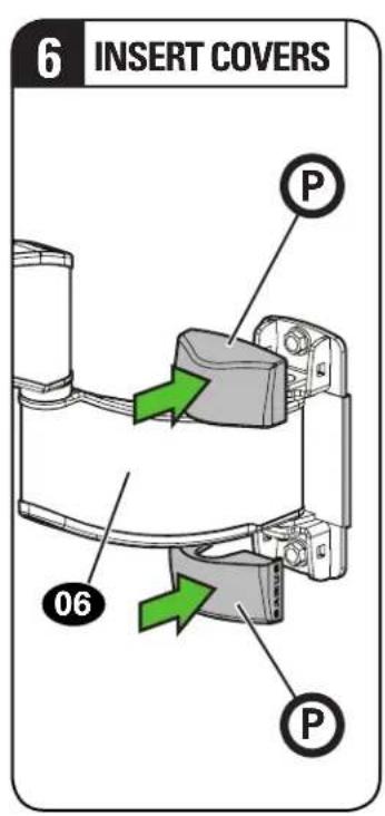
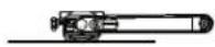
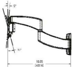
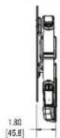
FULLY ASSEMBLED MOUNT
![3.36 [85.2] 11.64 [295.6] 12.02 [305.2]](/content/2026/04/694713/images/5edf47decbefcfe3822a21afaede6e7d8f0761228e7e6a1f8f90856200bf25a7.jpg)
TOP VIEW - EXTENDED
TOP VIEW - RETRACTED
3-D
natural_image
Technical line drawing of a mechanical assembly with two plates and a curved arm (no text or symbols)SIDE VIEW - EXTENDED
SIDE VIEW - RETRACTED
ONE MORE THING: BE A WINNER!

Register your new mount and tell us how you like it for a chance to win in our monthly sweepstakes.
Entering is quick and easy. Visit SANUS.com/1234 and follow three simple steps for your chance to win.
"Monthly Prize" sweepstakes rules and restrictions apply. Visit SANUS.com/1234 for details.
Milestone AV Technologies and its affiliated corporations and subsidiaries (collectively, "Milestone"), intend to make this manual accurate and complete. However, Milestone makes no claim that the information contained herein covers all details, conditions, or variations. Nor does it provide for every possible contingency in connection with the installation or use of this product. The information contained in this document is subject to change without notice or obligation of any kind. Milestone makes no representation of warranty, expressed or implied, regarding the information contained herein. Milestone assumes no responsibility for accuracy, completeness or sufficiency of the information contained in this document.
natural_image
Woman standing beside a modern TV wall with a yellow sofa, no visible text or symbolsWhen you share your handiwork with your friends, tag
sanusspaces
for a chance to be featured in the Inspiration Gallery on SANUS.com.

SANUS.com
WE MAKE IT EASY

SanusSystems
CHAT WITH US

pinterest.com/Sanus
BE INSPIRED

SanusSystems
WATCH AND LEARN
800-359-5520 • info@sanus.com • SANUS.com
SANUS • 6436 City West Parkway • Eden Prairie, MN 55344 USA
©2018 Milestone AV Technologies. All rights reserved. SANUS is a division of Milestone.
All other brand names or marks are used for identification purposes and are trademarks of their respective owners.
6901-602351 00