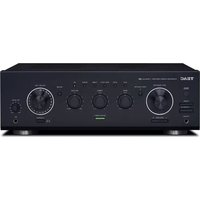
A-R630MK2 - Receiver TEAC - Free user manual and instructions
Find the device manual for free A-R630MK2 TEAC in PDF.


| Product Type | Stereo Receiver |
| Brand | TEAC |
| Model | A-R630MK2 |
| Dimensions (W × H × D) | 435 × 142 × 355 mm |
| Net Weight | 8.1 kg |
| Power Supply | AC 230 V, 50 Hz |
| Power Consumption | 200 W (operation), 0.5 W (standby) |
| Output Power | 90 W RMS (1 kHz, 4 Ω, 0.5 %), 60 W (1 kHz, 8 Ω, 0.5 %) |
| Total Harmonic Distortion | 0.02 % (1 kHz, 8 Ω, 45 W) |
| Speaker Impedance | 4–16 Ω (A or B), 8–16 Ω (A and B simultaneously) |
| Inputs | PHONO, TUNER, CD, AUX1, AUX2, TAPE1/CD-R, TAPE2, MIC |
| Outputs | Speakers A/B, TAPE (recording), PHONES (headphones), AC OUTLET (switched) |
| Input Sensitivity (PHONO) | 2.8 mV / 47 kΩ |
| Input Sensitivity (LINE) | 180 mV / 47 kΩ |
| Signal-to-Noise Ratio (PHONO) | 65 dB (IHF-A) |
| Signal-to-Noise Ratio (LINE) | 90 dB (IHF-A) |
| Frequency Response (LINE) | 5 Hz – 80 kHz (SOURCE DIRECT, 1 W) |
| Tone Controls | Bass: ±10 dB (100 Hz), Treble: ±10 dB (10 kHz) |
| Special Features | Source direct, Loudness, Balance, Mute, Tape Monitor, Automatic power saving |
| Supplied Accessories | Remote control (UR-1314), AAA batteries × 2, user manual |
| Care and Cleaning | Clean with a soft dry or slightly damp cloth; do not use chemical solvents |
| Safety | Do not expose to drips/splashes; do not obstruct ventilation; Class I with earth connection |
| Operating Temperature | +5 °C to +35 °C |
Frequently Asked Questions - A-R630MK2 TEAC
User questions about A-R630MK2 TEAC
0 question about this device. Answer the ones you know or ask your own.
Ask a new question about this device
Download the instructions for your Receiver in PDF format for free! Find your manual A-R630MK2 - TEAC and take your electronic device back in hand. On this page are published all the documents necessary for the use of your device. A-R630MK2 by TEAC.
USER MANUAL A-R630MK2 TEAC
Integrated Stereo Amplifier
OWNER'S MANUAL
MODE D'EMPLOI
MANUAL DEL USUARIO
BEDIENUNGSANLEITUNG
The lightning flash with arrowhead in an equilateral triangle is intended to alert the user to the presence of uninsulated "dangerous voltage" within the product's enclosure that could be of sufficient magnitude to constitute a risk of electric shock to persons.

The exclamation point in an equilateral triangle is intended to alert the user to the presence of important operating and maintenance (servicing) instructions in the literature accompanying the appliance.
WARNING: TO PREVENT FIRE OR SHOCK HAZARD, DO NOT EXPOSE THIS APPLIANCE TO RAIN OR MOISTURE.
CAUTION
- DO NOT REMOVE THE EXTERNAL CASES OR CABINETS TO EXPOSE THE ELECTRONICS. NO USER SERVICEABLE PARTS ARE INSIDE.
- IF YOU ARE EXPERIENCING PROBLEMS WITH THIS PRODUCT, CONTACT THE STORE WHERE YOU PURCHASED THE UNIT FOR A SERVICE REFERRAL. DO NOT USE THE PRODUCT UNTIL IT HAS BEEN REPAIRED.
- USE OF CONTROLS OR ADJUSTMENTS OR PERFORMANCE OF PROCEDURES OTHER THAN THOSE SPECIFIED HEREIN MAY RESULT IN HAZARDOUS RADIATION EXPOSURE.
1) Read these instructions.
2) Keep these instructions.
3) Heed all warnings.
4) Follow all instructions.
5) Do not use this apparatus near water.
6) Clean only with dry cloth.
7) Do not block any ventilation openings. Install in accordance with the manufacturer's instructions.
8) Do not install near any heat sources such as radiators, heat registers, stoves, or other apparatus (including amplifiers) that produce heat.
9) Do not defeat the safety purpose of the polarized or grounding-type plug. A polarized plug has two blades with one wider than the other. A grounding type plug has two blades and a third grounding prong. The wide blade or the third prong are provided for your safety. If the provided plug does not fit into your outlet, consult an electrician for replacement of the obsolete outlet.
10) Protect the power cord from being walked on or pinched particularly at plugs, convenience receptacles, and the point where they exit from the apparatus.
11) Only use attachments/accessories specified by the manufacturer.
12) Use only with the cart, stand, tripod, bracket, or table specified by the manufacturer, or sold with the apparatus. When a cart is used, use caution when moving the cart/apparatus combination to avoid injury from tip-over.
13) Unplug this apparatus during lightning storms or when unused for long periods of time.
14) Refer all servicing to qualified service person-
nel. Servicing is required when the apparatus has been damaged in any way, such as power-supply cord or plug is damaged, liquid has been spilled or objects have fallen into the apparatus, the apparatus has been exposed to rain or moisture, does not operate normally, or has been dropped.
- The apparatus draws nominal non-operating power from the AC outlet with its POWER or STANDBY/ON switch not in the ON position.
- The mains plug is used as the disconnect device, the disconnect device shall remain readily operable.
- Caution should be taken when using earphones or headphones with the product because excessive sound pressure (volume) from earphones or headphones can cause hearing loss.
CAUTION
- Do not expose this apparatus to drips or splashes.
- Do not place any objects filled with liquids, such as vases, on the apparatus.
- Do not install this apparatus in a confined space such as a book case or similar unit.
- The apparatus should be located close enough to the AC outlet so that you can easily reach the power cord plug at any time.
- If the product uses batteries (including a battery pack or installed batteries), they should not be exposed to sunshine, fire or excessive heat.
- CAUTION for products that use replaceable lithium batteries: there is danger of explosion if a battery is replaced with an incorrect type of battery. Replace only with the same or equivalent type.
WARNING
Products with Class I construction are equipped with a power supply cord that has a grounding plug. The cord of such a product must be plugged into an AC outlet that has a protective grounding connection.
Company names and product names in this document are the trademarks or registered trademarks of their respective owners.

natural_image
Symbolic icon of a person lifting a large object, enclosed in a circular frame (no text or symbols)⚠️ Precautions concerning batteries
Misuse of batteries could cause them to rupture or leak leading to fire, injury or the staining of nearby things. Please read and observe the following precautions carefully.
- Be sure to insert the batteries with correct positive (⊕) and negative (⊖) orientations.
- Use batteries of the same type. Never use different types of batteries together.
- If the remote control is not used for a long time (more than a month), remove the batteries to prevent them from leaking.
- If the batteries leak, wipe away the leakage inside the battery compartment and replace the batteries with new ones.
- Do not use batteries of types other than those specified. Do not mix new batteries with old ones or use different types of batteries together.
- Do not heat or disassemble batteries. Never throw batteries into fire or water.
- Do not carry or store batteries with other metallic objects. The batteries could short circuit, leak or explode.
- Never recharge a battery unless it is confirmed to be a rechargeable type.
For European Customers
Disposal of electrical and electronic equipment
(a) All electrical and electronic equipment should be disposed of separately from the municipal waste stream via collection facilities designated by the government or local authorities.
(b) By disposing of electrical and electronic equipment correctly, you will help save valuable resources and prevent any potential negative effects on human health and the environment.
(c) Improper disposal of waste electrical and electronic equipment can have serious effects on the environment and human health because of the presence of hazardous substances in the equipment.
(d) The Waste Electrical and Electronic Equipment (WEEE) symbol, which shows a wheeled bin that has been crossed out, indicates that electrical and electronic equipment must be collected and disposed of separately from household waste.
(e) Return and collection systems are available to end users. For more detailed information about the disposal of old electrical and electronic equipment, please contact your city office, waste disposal service or the shop where you purchased the equipment.
Disposal of batteries and/or accumulators
(a) Waste batteries and/or accumulators should be disposed of separately from the municipal waste stream via collection facilities designated by the government or local authorities.
(b) By disposing of waste batteries and/or accumulators correctly, you will help save valuable resources and prevent any potential negative effects on human health and the environment.
(c) Improper disposal of waste batteries and/or accumulators can have serious effects on the environment and human health because of the presence of hazardous substances in them.
(d) The WEEE symbol, which shows a wheeled bin that has been crossed out, indicates that batteries and/or accumulators must be collected and disposed of separately from household waste.
If a battery or accumulator contains more than the specified values of lead (Pb), mercury (Hg), and/or cadmium (Cd) as defined in the Battery Directive (2006/66/EC), then the chemical symbols for those elements will be indicated beneath the WEEE symbol.
(e) Return and collection systems are available to end users. For more detailed information about the disposal of waste batteries and/or accumulators, please contact your city office, waste disposal service or the shop where you purchased them.
Contents
Thank you for choosing TEAC. Read this manual carefully to get the best performance from this unit.
IMPORTANT SAFETY INSTRUCTIONS....2
Included items....5
Before using the unit....5
Connection....6
Identifying the parts....8
Remote control unit....10
Basic operation 10
Automatic power saving function 13
Troubleshooting 14
Specifications....14
DECLARATION OF CONFORMITY
We, TEAC AUDIO EUROPE, Liegnitzer Straße 6, 82194 Gröbenzell, Germany declare in own responsibility, the TEAC product described in this manual is in compliance with the corresponding technical standards.

Included items
Check to be sure the box contains all the included items shown below.
Please contact the store where you purchased this unit if any of these items are missing or have been damaged during transportation.
Remote control unit (UR-1314) × 1
Batteries (AAA) × 2
Owner's manual (this document) × 1
• See page 87 for warranty information.
Before using the unit
Read this before operation
- Even when this unit is in standby mode (off), it consumes standby power. To cut standby power consumption, use the POWER button to turn the unit off.
- As the unit may become warm during operation, always leave sufficient space around the unit for ventilation.
- The voltage supplied to the unit should match the voltage as printed on the rear panel. If you are in any doubt regarding this matter, consult an electrician.
- Choose the installation location of your unit carefully. Avoid placing it in direct sunlight or close to a source of heat. Also avoid locations subject to vibrations and excessive dust, heat, cold or moisture.
- Do not place the unit on the amplifier/receiver.
- Do not open the cabinet as this might result in damage to the circuitry or electrical shock. If a foreign object should get into the set, contact your dealer or service agency.
- When removing the power plug from the wall outlet, always pull directly on the plug, never yank the cord.
- Do not attempt to clean the unit with chemical solvents as this might damage the finish. Use a clean, dry or slightly damp cloth.
- Keep this manual in a safe place for future reference.
Maintenance
If the surface of the unit gets dirty, wipe with a soft cloth or use diluted neutral cleaning liquid. Be sure to remove any fluid completely. Do not use thinner or alcohol as they may damage the surface of the unit.
CAUTION:
- Switch off the power to all equipment before making connections.
- Read the instructions of each component you intend to use with this unit.
- Be sure to insert each plug securely. To prevent hum and noise, avoid bundling the signal interconnection cables together with the AC power cord or speaker cables.
flowchart
graph TD
    A["CD Player (CD-P650)"] --> B["TURNTABLE TAPE"]
    B --> C["LINE OUT"]
    B --> D["REMOTE CONTROL"]
    C --> E["L R"]
    D --> F["A R"]
    E --> G["REMO-CONTROL"]
    F --> H["C"]
    G --> I["D"]
    H --> J["E"]
    I --> K["F"]
    J --> L[" Speakers A"]
    K --> M[" Speakers B"]
    L --> N["AC wall socket"]
    M --> O["AC wall socket"]
    style A fill:#f9f,stroke:#333
    style B fill:#ccf,stroke:#333
    style C fill:#cfc,stroke:#333
    style D fill:#fcc,stroke:#333
    style E fill:#ffc,stroke:#333
    style F fill:#fcc,stroke:#333
    style G fill:#cff,stroke:#333
    style H fill:#ffc,stroke:#333
    style I fill:#cfc,stroke:#333
    style J fill:#fcc,stroke:#333
    style K fill:#ffc,stroke:#333
    style L fill:#cfc,stroke:#333
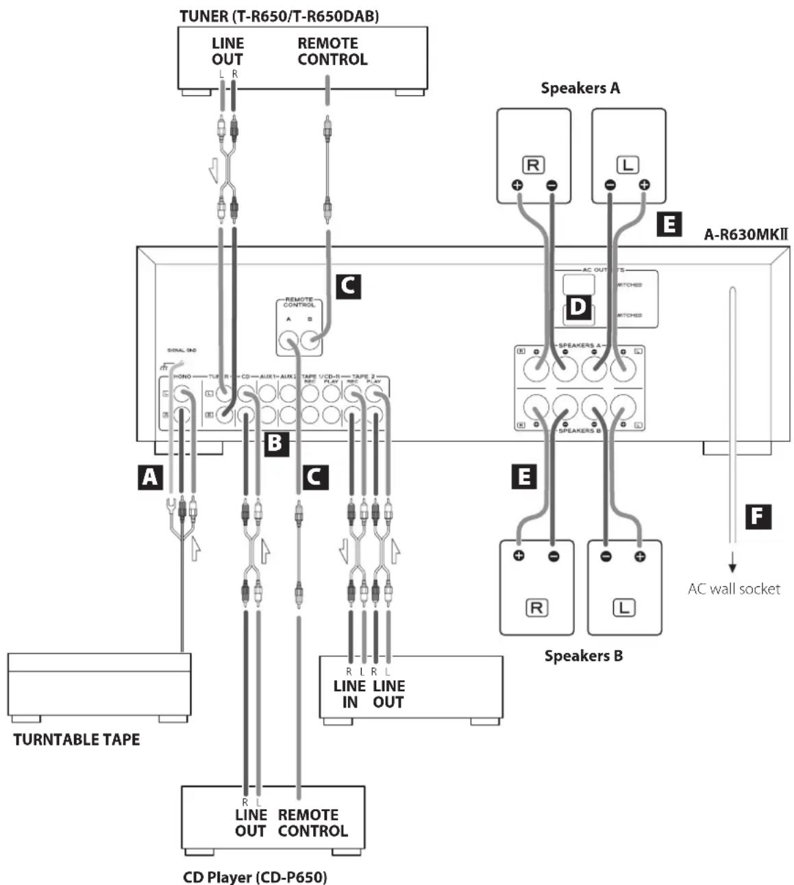
PHONO → Turntable
TUNER → Tuner (T-R650/T-R650DAB)
CD → CD player (CD-P650)
AUX 1/AUX 2 → Audio component, etc.
TAPE1/CD-R → Cassette tape deck, CD recorder, etc.
TAPE2 → Cassette tape deck
A PHONO jacks/SIGNAL GND terminal
Connect the turntable's RCA pin cords to PHONO jacks. Make sure to connect:
white plug → white jack (L: left channel) red plug → red jack (R: right channel)
Connect the turntable's ground cord to SIGNAL GND terminal.
natural_image
Diagram showing a mechanical assembly process: one tool changing the component with arrows indicating motion (no text or symbols present)B AUDIO IN/OUT jacks
Analog 2-channel audio signal is input or output from these jacks. Connect the component with commercially-available RCA cables.
Make sure to connect:
white plug → white jack (L: left channel) red plug → red jack (R: right channel)

- Be sure to insert each plug securely. To prevent hum and noise, avoid bundling the signal connection cables together with the AC power cord or speaker cables.
C REMOTE CONTROL jacks
If you have TEAC T-R650, TR-650DAB or CD-P650, connect the REMOTE CONTROL jack (A or B) of each component by the remote control cord (provided with the T-R650, T-R650DAB or CD-P650).
D AC OUTLET (SWITCHED)
This outlet is active when the unit is on or in standby.
Caution:
Make sure that the total power consumption of all equipment connected to the outlet does not exceed 500 mA or 100 watts.
E Speaker Connections
Caution:
To avoid damaging the speakers with a sudden high-level signal, be sure to switch the power off before connecting the speakers.
- Check the impedance of your speakers. Connect speakers with an impedance of 4 to 16 ohms when using only one pair of speakers (SPEAKERS A or SPEAKERS B). When using two pairs of speakers simultaneously, the impedance should be 8 to 16 ohms.
- The black speaker terminals are (negative).
Generally, the ⊕ side of the speaker cable is marked to make it distinguishable from the ⊖ side of the cable. Connect this marked side to the ⊕ terminal and the unmarked side to the black ⊖ terminal.
Caution:
The metal portions of the two separate wires should not touch or an electrical short can occur. Shorted wires can create a fire hazard or induce a failure in your equipment.
Connecting speakers A, B
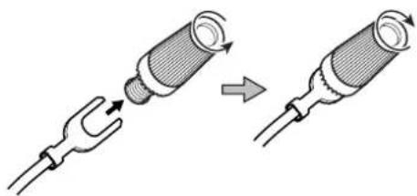
- Remove about 1 cm of sheathing from the ends of the speaker cables and twist the exposed core wires well.
- Turn the terminal cap counterclockwise to loosen it. The speaker terminal caps cannot be fully removed from the base.
- Insert the wire into the terminal fully and turn the terminal cap clockwise to securely connect it.
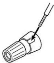
- Make sure none of the wire insulation is under the terminal, only the bare, stripped wire.
● Make sure the wire is fastened firmly by pulling the cable lightly.
Connecting with banana plugs
You can use commercially-available banana plugs to connect speakers. After connecting the banana plugs to the speaker cables, insert the plugs into the terminals.
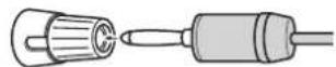
- Keep the terminal cap tightened when in use.
- Carefully read the instructions for the banana plugs that you are using.
Notice about the European model
In accordance with European safety regulations, connecting banana plugs to speaker terminals is not allowed on European models. The holes into which banana plugs could be inserted have been covered with black caps. Connect speakers using bare wires or spade lugs. If a black cap should become separated from its terminal, return it to its original position.
F AC power cord
Confirm that the power plug is plugged into a working outlet. Unplug the cord from the outlet when not using the unit for a long time.
He sure to connect the power cord to an AC outlet that supplies the correct voltage. Connection to an outlet that supplies incorrect voltage could cause fire or electric shock. Hold the power plug when plugging it into an outlet or unplugging it. Never pull or yank on the power cord.
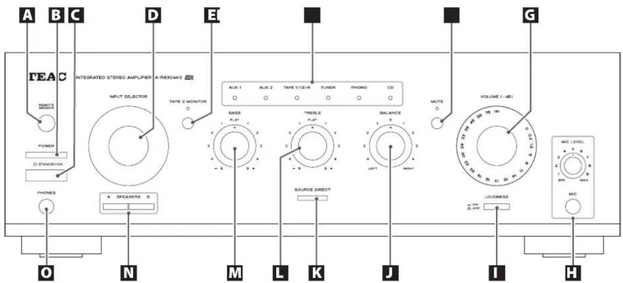
A Remote Sensor
When operating the remote control unit, point it towards the REMOTE SENSOR.
B POWER
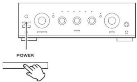
Press this switch to put the unit into standby mode or turn it off.
C STANDBY/ON
When the power switch on the main unit is down, use this button to turn the unit on or put it in standby. The standby indicator lights when the unit is in standby mode. When the unit is turned on, the light goes off.
D INPUT SELECTOR
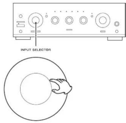
Use this knob (or buttons on the remote control unit) to select a source. One of the indicators will light to show the selected source.
E TAPE 2 MONITOR
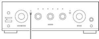
When a cassette tape deck is connected to the TAPE 2 jacks, use this button to turn on or off the tape monitor function. The indicator lights when the tape monitor function is on.
F MUTE
Use this button to mute the sound. This indicator blinks when the sound is muted.
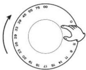
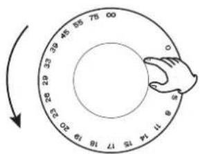
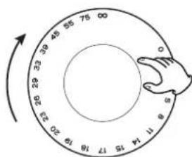
G VOLUME
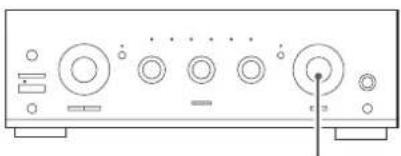
Turn this knob (or press the VOLUME buttons on the remote control unit) to adjust the volume.
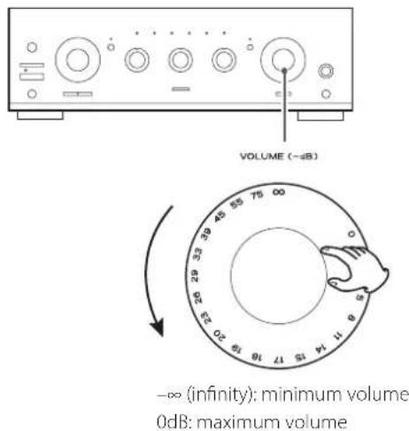
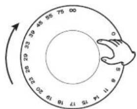
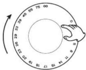
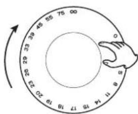
For volume, 0 is the maximum and - is the minimum. Before turning the unit on, turn the VOLUME knob to the minimum value (- ) . Failure to do so could result in sudden loud noise, which could damage speakers, harm hearing or cause other trouble
H MIC Jack and MIC LEVEL knob
With the microphone plugged into this jack, the sound picked up from the microphone will be heard together with the source sound selected by the INPUT SELECTOR. Turn the MIC LEVEL knob to adjust the input level of the microphone.
LOUDNESS
When the volume level is low, use this to boost low and high frequencies, which can be more difficult to hear.
J BALANCE
Use this knob to adjust the balance of the speakers. Normally, set the knob to the center position.
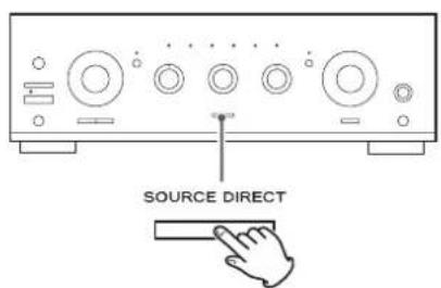
K SOURCE DIRECT
Press this button to turn on or off the source direct function. When the source direct function is set to on, the button lights and you can listen to the sound without tone effects.
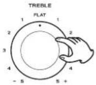
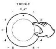
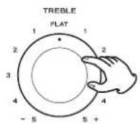
L TREBLE
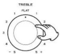
Use this knob to adjust the level of high frequency information.
- When the source direct function is on, this knob has no effect.
M BASS
Use this knob to adjust the level of low frequency information.
- When the source direct function is on, this knob has no effect.
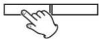
N SPEAKERS buttons
Use these buttons to turn the speakers on and off.
When the A button is down:
Sound is output from speakers connected to the SPEAKERS A terminals.
When the B button is down:
Sound is output from speakers connected to the SPEAKERS B terminals.
When both the A and B buttons are down:
Sound is output from speakers connected to the terminals of both SPEAKERS A and B.
When neither A or B button is down:
No sound is output from the speakers. Use this setting when listening through headphones.
PHONES jack
For private listening, insert the headphones plug into this jack, and adjust the volume by turning the VOLUME knob.
- Plugging headphones in here will not disable speaker output. Use the SPEAKERS A and B buttons to turn them off.
Remote Control Unit
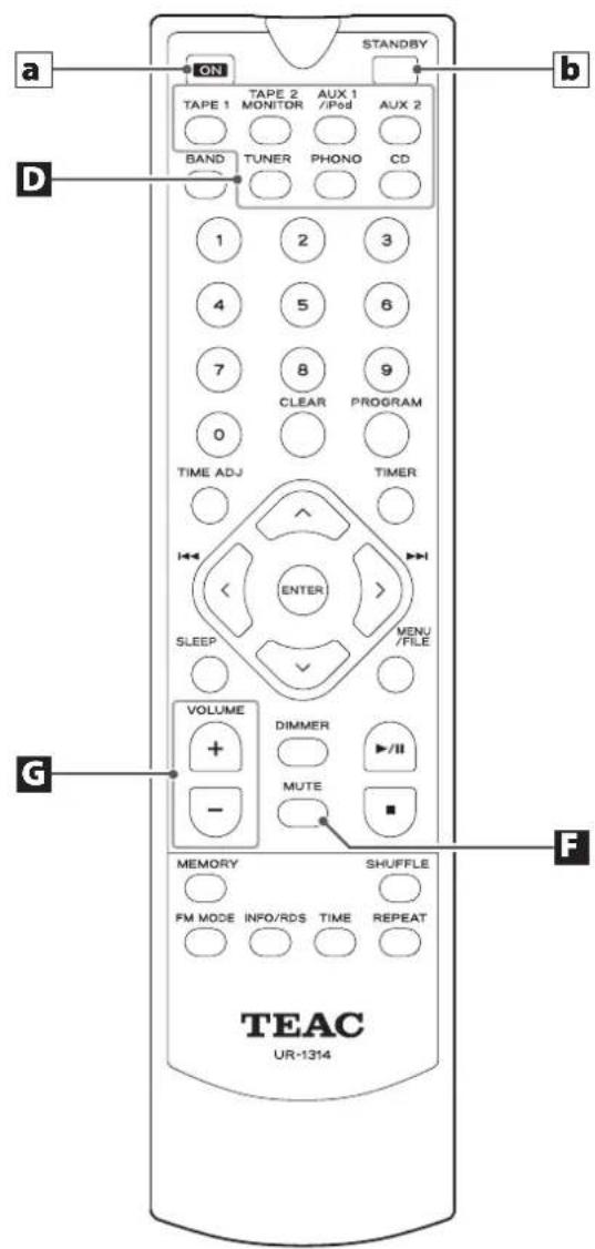
When operating the TEAC CD Player (CD-P650) or the tuner (T-R650/T-R650DAB) using the remote control unit UR-1314, select a source first using INPUT SELECTOR buttons (boxed D) on the remote control unit.
In this manual, we explain the buttons used with the A-R630MKII.
a ON
When the POWER switch on the main unit is down, use this button to turn the unit on.
b STANDBY
When the POWER switch on the main unit is down, use this button to put the unit into standby mode.
Other buttons are used for operation of TEAC's CD-P650, T-R650 and T-R650DAB.
Note:
- To simplify explanations, instructions in this manual refer to the names of the buttons and controls on the front panel only. Associated controls on the remote control will also operate similarly.
Remote control unit
When operating the remote control unit, point it towards the REMOTE SENSOR on the front panel of the amplifier (or other TEAC component).
- Even if the remote control unit is operated within the effective range, remote control operation may be impossible if there are any obstacles between the unit and the remote control.
- If the remote control unit is operated near other appliances which generate infrared rays, or if other remote control devices using infrared rays are used near the unit, it may operate incorrectly. Conversely, the other appliances may operate incorrectly.
Battery Installation
natural_image
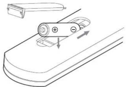
Diagram of a battery on a ramp with directional arrows indicating motion (no text or symbols)- Remove the battery compartment cover.
- Insert two "AAA" dry batteries. Make sure that the batteries are inserted with their positive "⊕" and negative "⊖" poles positioned correctly.
- Close the cover.
Battery Replacement
If the distance required between the remote control unit and main unit decreases, the batteries are exhausted. In this case replace the batteries with new ones.
For more information about collection of batteries, please contact your local municipality, your waste disposal service or the point of sale where you purchased the items.
Basic operation
To protect speakers from a sudden high-level signal, turn the VOLUME knob counterclockwise to minimize the volume.
2 Press the POWER switch.
The unit enters standby mode, and the standby indicator lights.
3 Press the STANDBY/ON switch to turn the unit on.
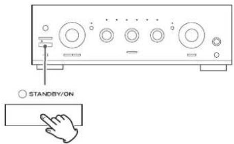
The standby indicator goes off.
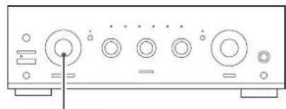
4 Select a source by turning the INPUT SELECTOR (or pressing one of the input buttons on the remote control unit).
Tape Monitor Function
If you want to select the source connected to the TAPE 2 jacks, press the TAPE 2 MONITOR button to turn the tape monitor function on. The TAPE 2 MONITOR indicator lights.
Press the TAPE MONITOR button again to cancel the tape monitor function.
natural_image
Front view of a computer control panel with multiple buttons and indicator lights (no text or labels visible)TAPE 2 MONITOR ○

- When the tape monitor function is on, sources other than TAPE 2 cannot be heard. Be sure to turn the function off while listening to other sources.
5 Play the source, and gradually turn up the volume to the required level by turning the VOLUME knob.
natural_image
Front view of a computer control panel with multiple buttons and indicator lights (no text or labels visible)VOLUME (-dB)
Recording
You can record the sound from the source shown by the lit input indicator using a recording device connected to TAPE 1/CD or TAPE 2.
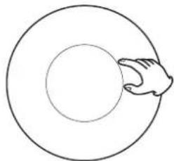
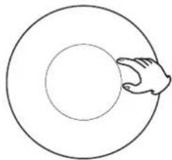
- Select a source to be recorded by turning the INPUT SELECTOR.
natural_image
Front panel of a computer control unit with multiple buttons and indicator lights (no text or labels visible)INPUT SELECTOR
natural_image
Simple line drawing of a hand holding a circular object (no text or symbols)-
Start playback on the source device to be recorded.
-
Start recording.
-
The following controls have no effect on the recorded signal: VOLUME, BALANCE, BASS and TREBLE knobs, MUTE and LOUDNESS buttons.
- By turning the TAPE 2 MONITOR button on, you can listen to the sound as it is being recorded by the device connected to TAPE 2.
● This unit cannot dub from TAPE 2 to TAPE 1/CD.
Selecting the speakers
natural_image
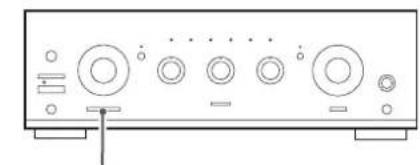
Front panel of a computer control unit with multiple buttons and indicator lights (no text or labels visible)A SPEAKERS B
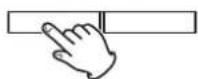
Use the SPEAKERS A and B buttons to turn the speakers on and off.
When the A button is down:
Sound is output from speakers connected to the SPEAKERS A terminals.
When the B button is down:
Sound is output from speakers connected to the SPEAKERS B terminals.
When both the A and B buttons are down:
Sound is output from speakers connected to the terminals of both SPEAKERS A and B.
When neither A or B button is down:
No sound is output from the speakers. Use this setting when listening through headphones.
Listening through headphones
natural_image
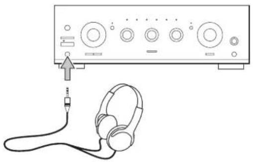
Line drawing of an audio recording device with headphones connected to a power connector (no text or symbols)For private listening, first reduce the volume level on the receiver to minimum. Then insert the plug from your headphones into the PHONES jack, and adjust the volume by turning the VOLUME knob.
- Plugging headphones into the PHONES jack does not disable speaker output. Use the SPEAKERS A and B buttons to turn them off.
CAUTION
Always lower the volume level prior to plugging in your headphones. TO AVOID DAMAGING YOUR HEARING - Do not place your headphones on your head until after you have plugged them in.
Muting
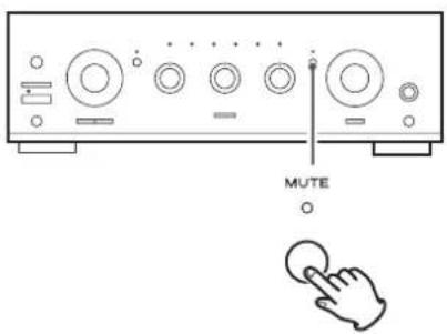
To mute the sound temporarily, press the MUTE button. Press the MUTE button again to restore the sound.
● While muting is engaged, the MUTE indicator blinks.
LOUDNESS button
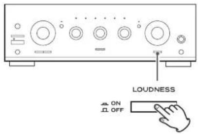
When the volume level is low, use this to boost low and high frequencies, which can be more difficult to hear.
Set this button to the OFF position when listening at normal levels.
How to adjust the balance between the left and right speakers
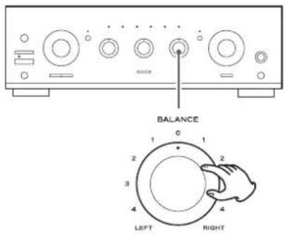
Turn the BALANCE knob to adjust the balance of the speakers. Normally, set the knob to the center position.
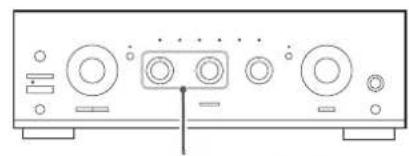
Tone Control
natural_image
Front view of a computer audio workstation (no text or labels visible)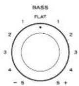
Turn the BASS knob to adjust the level of low frequency information.
Turn the TREBLE knob to adjust the level of high frequency information.
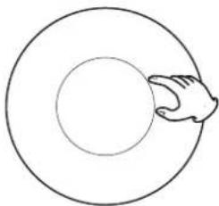
Source Direct
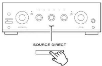
Press this button to turn on or off the source direct function.
When the source direct function is set to on, the button lights and you can listen to the sound without tone effects.
Automatic power saving function
This unit has an automatic power saving function.
When the unit is shipped new, the automatic power saving function is on, so it will automatically enter standby mode if none of the following controls on the main unit (or any remote control buttons) are used for the set amount of time (default setting: 8 hours).
- INPUT SELECTOR
• TAPE 2 MONITOR button - MUTE button
- SOURCE DIRECT button
Checking the setting
When the unit is on, press the TAPE 2 MONITOR button for at least 5 seconds. This will cause an indicator to blink according to the setting.
This table shows the relationship between the setting and the blinking indicator.
| Indicator Setting time | |
| AUX1 1 hour | |
| AUX2 2 hours | |
| TAPE1/CD-R 3 hours | |
| TUNER 4 hours | |
| PHONO 6 hours | |
| CD 8 hours | |
| TAPE 2 MONITOR Automatic power saving off | |
To end setting confirmation mode, press the TAPE 2 MONITOR button for at least 3 seconds.
CAUTION
No sound will be output from speakers or headphones while this setting is being checked.
Changing the setting
1 When the power is off, press the POWER button while pressing and holding the TAPE 2 MONITOR button to turn the unit on.
The CD indicator will blink.
● The setting is always set to 8 hours when the unit is turned on.
2 Press the TAPE 2 MONITOR button to change the setting.
The setting and corresponding indicator change in the following order each time you press the TAPE 2 MONITOR button.
→ 8 hours (CD) → automatic power saving off (TAPE 2 MONITOR)
→1 hour (AUX 1) →2 hours (AUX 2) →3 hours (TAPE 1/CD-R)
→ 4 hours (TUNER) → 6 hours (PHONO) →
3 Press the STANDBY/ON button to complete the setting.
CAUTION
If the POWER switch is turned off or the power supply to the unit is otherwise interrupted, the setting will be restored to its default value of eight hours.
Troubleshooting
If you experience problems with this unit, please take the time to look through this chart and see if you can solve the problem yourself before you call your dealer.
No power
→ Check the connection to the AC power source. Check and make sure the AC source is not a switched outlet and if it is, the switch is turned on. Make sure there is power to the AC outlet by plugging another item such as a lamp or fan.
No sound from speakers.
→ Adjust the volume.
→ Set the BALANCE control to "0".
→ Check the connection to the speakers.
If your speakers are connected to the SPEAKERS A (or B) terminals, make sure the SPEAKERS A (or B) button on the front panel is down.
If the tape monitor function is ON, press the TAPE 2 MONITOR button to turn it off.
The volume of SPEAKERS A is different from that of B.
The volume and sound quality may differ depending on the speaker's size, etc. If you want to use SPEAKERS A and B simultaneously with the same volume, connect exactly the same type of speakers to the SPEAKERS A and B terminals.
The sound is noisy or humming.
The unit is too close to a TV set or similar appliances. Relocate the units so they no longer interfere with each other, or turn them off.
Connect the turntable's ground cord to the SIGNAL GND terminal.
Sound cuts off during listening to the music or no sound even though power is ON.
→ Speaker impedance is less than prescribed for this unit.
→ Turn the power off and reduce the volume.
Low bass response.
→ Speaker polarity (⊕/⊖) is reversed. Check all speakers for correct polarity.
Remote control doesn't work.
→ Press the POWER switch on the main unit to turn it on.
→ If the batteries are dead, change the batteries.
→ Use remote control unit within the range (5 m) and point at the front panel.
→ Clear obstacles between the remote control unit and the main unit.
→ If a strong light is near the unit, turn it off.
If normal operation is not restored, unplug the power cord from the outlet and plug it again.
Specifications
Amplifier Section
Continuous Power Output .... 90 W RMS (1 kHz, 4 Ω, 0.5%) 60 W (1 kHz, 8 Ω, 0.5%)
Total Harmonic Distortion....0.02% (1 kHz, 8 Ω, 45 W)
Output connections....Speakers A or B: 4–16 Ω load Speakers A and B: 8–16 Ω load
Input Sensitivity/Impedance..... PHONO: 2.8 mV/47 kΩ LINE*: 180 mV/47 kΩ
MIC: 1.4 mV/22 kΩ
Signal-to-Noise Ratio (IHF-A)....PHONO: 65 dB LINE*: 90 dB
Output Level/Impedance.....TAPE: 150 mV/3.3 kΩ
Frequency Response.....PHONO: 20 to 20,000 Hz, ±1 dB (RIAA) LINE*: 5 to 80,000 Hz, (SOURCE DIRECT, 1 W)
Tone Control.....BASS: ±10 dB at 100 Hz TREBLE: ±10 dB at 10 kHz
Mute -20 dB
General
Power Requirements....AC 230 V, 50 Hz
Power Consumption 200 W Standby 0.5 W
Dimensions (W × H × D)....435 × 142 × 355 mm (17 1/4" × 5 5/8" × 14)
Weight (net) 8.1 kg (17 7/8 lb)
Operating temperature....+5°C to +35°C
Included accessories
Remote control unit (UR-1314) × 1
Batteries (AAA) × 2
Owner's manual (this document) × 1
* LINE means TUNER, CD, AUX1, AUX2, TAPE1/CD-R, TAPE2.
- Design and specifications are subject to change without notice.
● Weight and dimensions are approximate.
● Illustrations may differ slightly from production models.
INSTRUCTIONS DE SÉCURITÉ IMPORTANTES
DÉCLARATION DE CONFORMITÉ
Identification des parties....20
natural_image
Diagram showing two mechanical components with arrows indicating motion, no text or symbols presentB Prises AUDIO IN/OUT
natural_image
Diagram of a battery moving on an inclined conveyor belt with directional arrows indicating motion (no text or symbols)natural_image
Line drawing of an audio headset connected to a CD-ROM interface (no text or symbols)natural_image
Front panel view of a computer interface with buttons and ports (no text or symbols visible)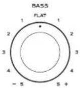
natural_image
Diagram showing two mechanical components with arrows indicating motion, no text or symbols presentB Conectores AUDIO IN/OUT
natural_image
Diagram of a battery moving on a surface with directional arrows indicating motion (no text or symbols)natural_image
Front view of a control panel with multiple knobs and buttons (no text or labels visible)VOLUME (-dB)
natural_image
Front view of a computer control panel with multiple buttons and indicator lights (no text or labels visible)
natural_image
Front view of a computer control panel with multiple buttons and indicator lights (no text or labels visible)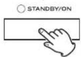
Grabación
natural_image
Simple line drawing of a hand holding a circular object (no text or symbols)natural_image
Line drawing of an audio headset connected to a CD-ROM interface (no text or symbols)natural_image
Diagram showing two mechanical components with arrows indicating motion, no text or symbols presentB AUDIO IN/OUT-Anschlüsse
natural_image
Diagram of a battery moving on a surface with directional arrows indicating motion (no text or symbols)natural_image
Front view of a computer control panel with buttons and indicator lights (no text or symbols visible)TAPE 2 MONITOR
O
natural_image
Front view of a computer control panel with multiple buttons and indicator lights (no text or labels visible)VOLUME (-#B)
Aufnahmebetrieb
natural_image
Front panel of a computer audio device showing multiple knobs and buttons (no text or labels visible)INPUT SELECTOR
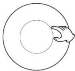
natural_image
Simple line drawing of a hand touching a circular ring (no text or symbols)natural_image
Front view of a computer control panel with multiple buttons and indicator lights (no text or labels visible)A SPEAKERS B

natural_image
Line drawing of an audio headset connected to a CD-ROM interface (no text or symbols)natural_image
Diagram showing two mechanical components with arrows indicating motion, no text or symbols presentB Connettori AUDIO IN/OUT
natural_image
Diagram of a battery moving on a ramp with directional arrows indicating motion (no text or symbols)natural_image
Front view of a control panel with multiple knobs and buttons (no text or labels visible)VOLUME (-dB)
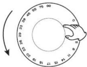
-∞ (infinito): volume minimo
0 dB: volume massimo
natural_image
Front view of a computer control panel with multiple buttons and indicator lights (no text or labels visible)
natural_image
Front panel of a computer control unit with multiple buttons and indicator lights (no text or labels visible)
natural_image
Line drawing of an audio recording device with headphones connected to a speaker (no text or symbols)natural_image
Front view of a computer monitor with ports and buttons (no text or symbols visible)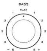
BASS
Dimensioni (L × A × P).... 435 × 142 × 355 mm
Peso (netto) 8,1 kg
TAPE1/CD-R → Cassettedeck, CD recorder, enz.
TAPE2 → Cassettedeck
natural_image
Diagram of a battery being carried on a surface, showing motion direction (no text or symbols)natural_image
Front view of a computer control panel with multiple buttons and indicator lights (no text or labels visible)INPUT SELECTOR
natural_image
Simple line drawing of a hand holding a circular object (no text or symbols)natural_image
Front view of a computer control panel with multiple buttons and indicator lights (no text or labels visible)INPUT SELECTOR
natural_image
Simple line drawing of a hand holding a circular object (no text or symbols)natural_image
Front view of a control panel with multiple buttons and indicator lights (no text or symbols visible)VOLUME (-dB)
natural_image
Front panel of a computer control unit with multiple knobs and buttons (no visible text or labels)INPUT SELECTOR
natural_image
Simple line drawing of a hand touching a circular ring (no text or symbols)natural_image
Line drawing of an audio recording device with headphones connected to a power connector (no text or symbols)Source Direct (Bron direct)
natural_image
Diagram showing a mechanical component being inserted into a cylindrical device, with no text or symbols present.B AUDIO IN/OUT-anslutningar
natural_image
Diagram of a battery moving on a surface with directional arrows indicating motion (no text or symbols)natural_image
Front panel of a computer control unit with multiple buttons and indicator lights (no text or labels visible)TAPE 2 MONITOR ○
natural_image
Front panel of a computer control unit with multiple buttons and indicator lights (no text or labels visible)VOLUME (-dB)
Inspelning
natural_image
Front view of a control panel with multiple buttons and indicator lights (no text or labels visible)INPUT SELECTOR
natural_image
Simple line drawing of a hand touching a circular ring (no text or symbols)natural_image
Front view of a control panel with multiple knobs and buttons (no text or labels visible)A SPEAKERS B
natural_image
Line drawing of an audio headset connected to a CD-ROM interface (no text or symbols)natural_image
Front view of a computer audio workstation (no text or labels visible)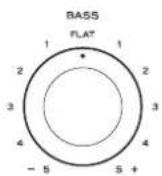
This product is subject to the legal warranty regulations of the country of purchase. In case of a defect or a problem, please contact the dealer where you bought the product.
In other countries/areas
This warranty gives you specific legal rights, and you may also have other rights that vary by country, state or province.
If you have a warranty claim or request, please contact the dealer where you bought the product.
TEAC AMERICA, INC. 7733 Telegraph Road, Montebello, California 90640 U.S.A. Phone: +1-323-726-0303
TEAC AUDIO EUROPE Liegnitzer Straße 6, 82194 Gröbenzell, Germany Phone: +49-8142-4208-141

- Integrated Stereo Amplifier
- CAUTION
- WARNING
- ⚠️ Precautions concerning batteries
- For European Customers
- Disposal of electrical and electronic equipment
- Disposal of batteries and/or accumulators
- Contents
- DECLARATION OF CONFORMITY
- Included items
- Before using the unit
- Read this before operation
- Maintenance
- CAUTION:
- A PHONO jacks/SIGNAL GND terminal
- B AUDIO IN/OUT jacks
- C REMOTE CONTROL jacks
- D AC OUTLET (SWITCHED)
- E Speaker Connections
- Connecting speakers A, B
- Connecting with banana plugs
- Notice about the European model
- F AC power cord
- A Remote Sensor
- B POWER
- C STANDBY/ON
- D INPUT SELECTOR
- E TAPE 2 MONITOR
- F MUTE
- G VOLUME
- H MIC Jack and MIC LEVEL knob
- LOUDNESS
- J BALANCE
- K SOURCE DIRECT
- L TREBLE
- M BASS
- N SPEAKERS buttons
- When the A button is down:
- When the B button is down:
- When both the A and B buttons are down:
- When neither A or B button is down:
- PHONES jack
- Remote Control Unit
- a ON
- b STANDBY
- Other buttons are used for operation of TEAC's CD-P650, T-R650 and T-R650DAB.
- Note:
- Battery Replacement
- Basic operation
- Tape Monitor Function
- Recording
- Selecting the speakers
- Listening through headphones
- Muting
- LOUDNESS button
- How to adjust the balance between the left and right speakers
- Tone Control
- Source Direct
- Automatic power saving function
- Checking the setting
- Changing the setting
- Troubleshooting
- No power
- No sound from speakers.
- The volume of SPEAKERS A is different from that of B.
- The sound is noisy or humming.
- Sound cuts off during listening to the music or no sound even though power is ON.
- Low bass response.
- Remote control doesn't work.
- Specifications
- Amplifier Section
- General
- Included accessories
- INSTRUCTIONS DE SÉCURITÉ IMPORTANTES
- DÉCLARATION DE CONFORMITÉ
- B Prises AUDIO IN/OUT
- B Conectores AUDIO IN/OUT
- Grabación
- B AUDIO IN/OUT-Anschlüsse
- Aufnahmebetrieb
- B Connettori AUDIO IN/OUT
- BASS
- Source Direct (Bron direct)
- B AUDIO IN/OUT-anslutningar
- Inspelning
- In other countries/areas
Brand : TEAC
Model : A-R630MK2
Category : Receiver