Alyas Pro E - Air Conditioning OLIMPIA SPLENDID - Free user manual and instructions
Find the device manual for free Alyas Pro E OLIMPIA SPLENDID in PDF.

User questions about Alyas Pro E OLIMPIA SPLENDID
0 question about this device. Answer the ones you know or ask your own.
Ask a new question about this device
Download the instructions for your Air Conditioning in PDF format for free! Find your manual Alyas Pro E - OLIMPIA SPLENDID and take your electronic device back in hand. On this page are published all the documents necessary for the use of your device. Alyas Pro E by OLIMPIA SPLENDID.
USER MANUAL Alyas Pro E OLIMPIA SPLENDID
natural_image
White air conditioner unit with blank white panel and ventilation slots (no text or symbols visible)Caution: risk of fire
text_image
Diagram illustrating airflow or ventilation conditions for a wall-mounted air conditioner, including cooling unit, monitor, and oven with Chinese annotations.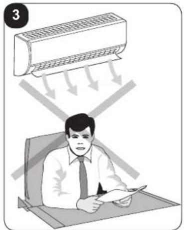
natural_image
Illustration of a person sitting at a desk under a ceiling-mounted air conditioner, with arrows indicating airflow direction (no text or symbols)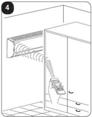
natural_image
Line drawing of a hand holding a remote control device near a wall-mounted air conditioner unit (no text or symbols)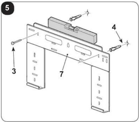
text_image
5 4 3 7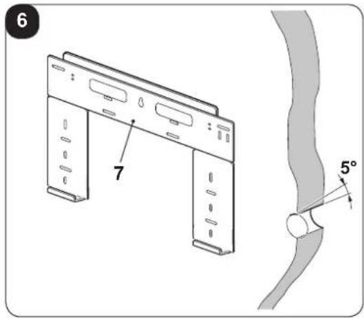
text_image
6 7 5°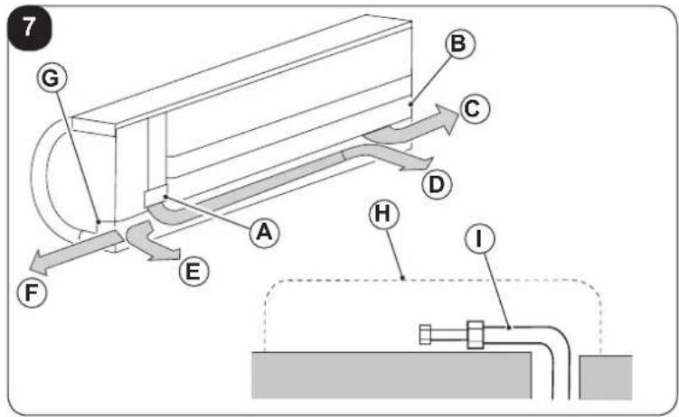
text_image
7 G B C D A H E F I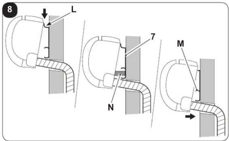
text_image
8 L 7 N M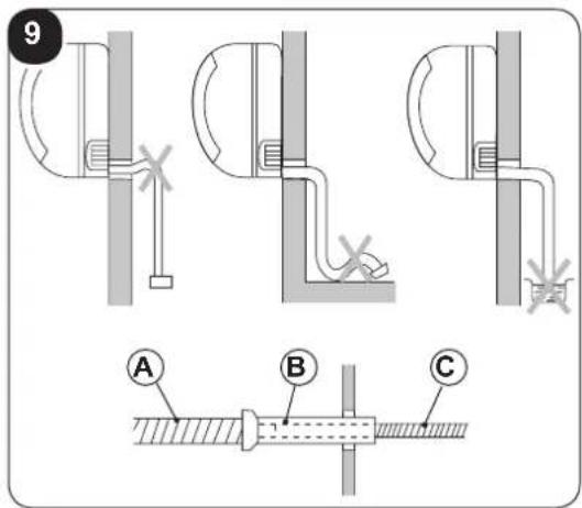
text_image
9 A B C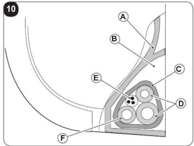
text_image
10 A B C D E F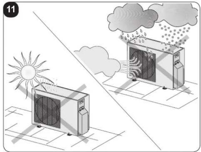
natural_image
Illustration of two air conditioning machines under a sun and cloud, with no text or symbols present.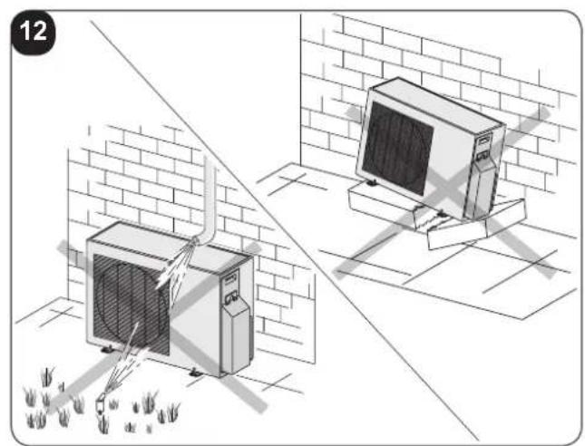
natural_image
Illustration of two air conditioning machines on a brick wall, one emitting exhaust smoke, with ground vegetation and no visible text or symbols.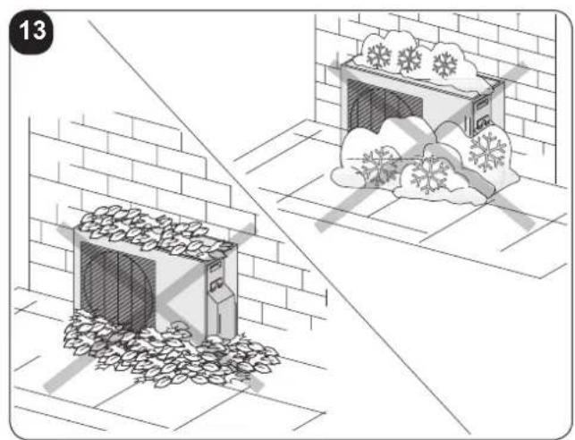
natural_image
Illustration showing a snow-covered building and cloud in a garden setting (no text or symbols)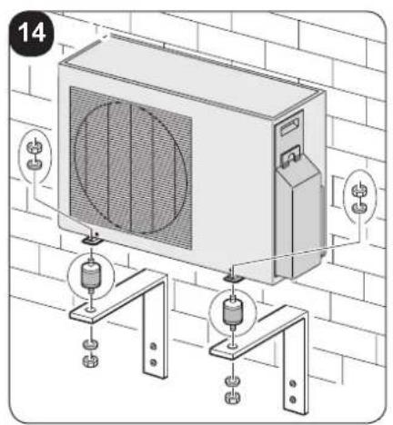
text_image
14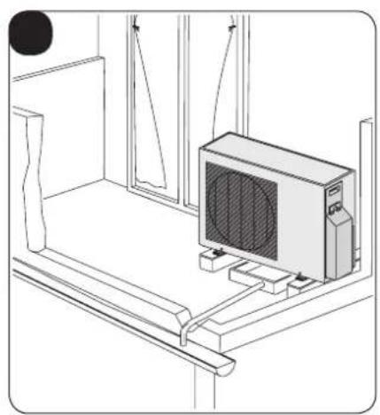
natural_image
Line drawing of a room interior with a computer monitor and hanging cables (no text or symbols)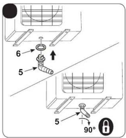
text_image
6 5 5 90°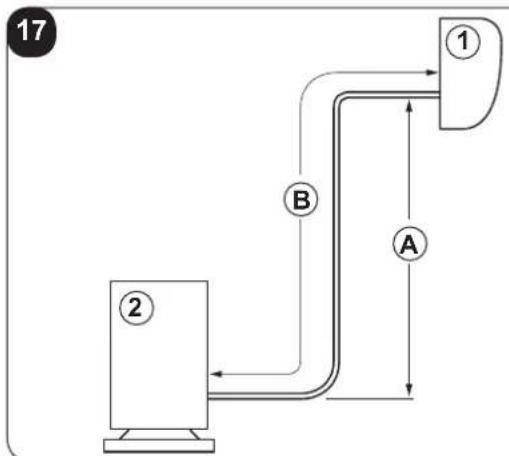
flowchart
graph TD
    A["①"] --> B["②"]
    B --> A
    style A fill:#f9f,stroke:#333
    style B fill:#ccf,stroke:#333
flowchart
graph TD
    A["①"] --> B["②"]
    B --> C["③"]
    C --> D["A"]
    style A fill:#f9f,stroke:#333
    style B fill:#ccf,stroke:#333
    style C fill:#cfc,stroke:#333
    style D fill:#fcc,stroke:#333
natural_image
Mechanical assembly diagram showing two configurations of a mechanical clamp or bracket with no visible text or symbols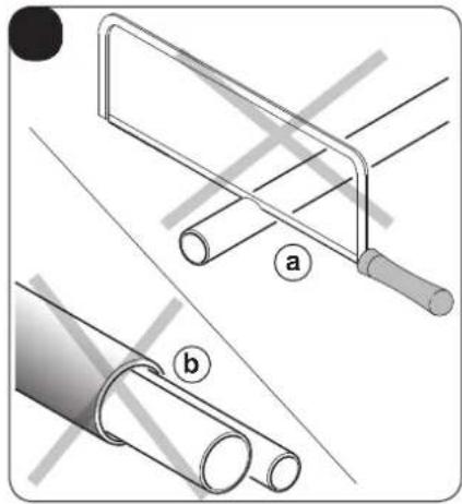
natural_image
Technical illustration of two pipe fittings with labeled parts (a and b), showing different installation methods (no text or symbols present)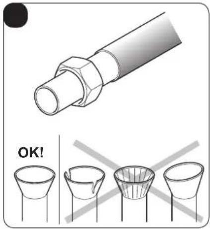
text_image
OK!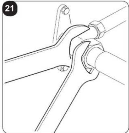
natural_image
Technical line drawing of a mechanical joint or bracket assembly (no text or symbols)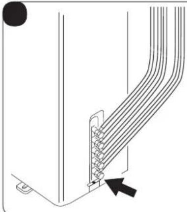
natural_image
Diagram of a cable or connector assembly with multiple strands and a black arrow pointing to a specific component (no text or symbols present)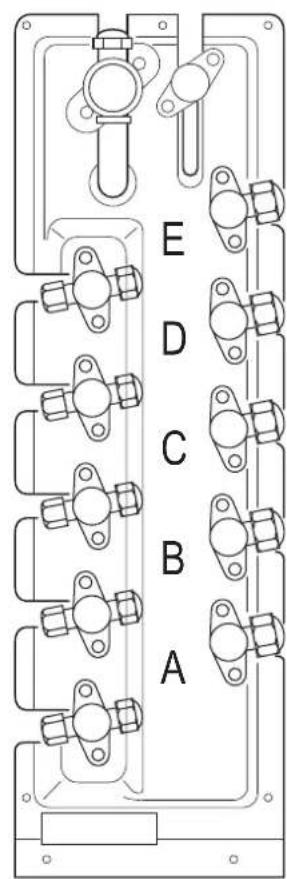
text_image
E D C B A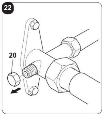
text_image
22 20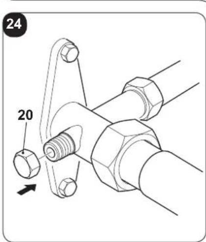
text_image
24 20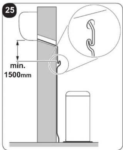
text_image
25 min. 1500mm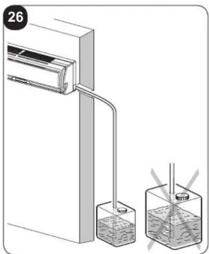
text_image
26 5mmHg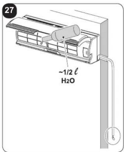
text_image
27 ~1/2 ℓ H₂O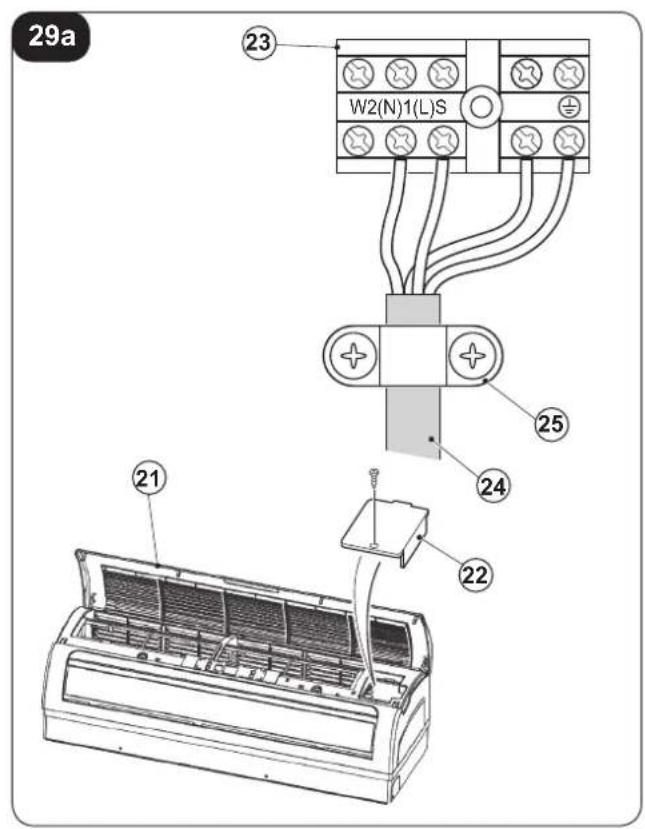
text_image
29a W2(N)1(L)S 23 25 24 22 21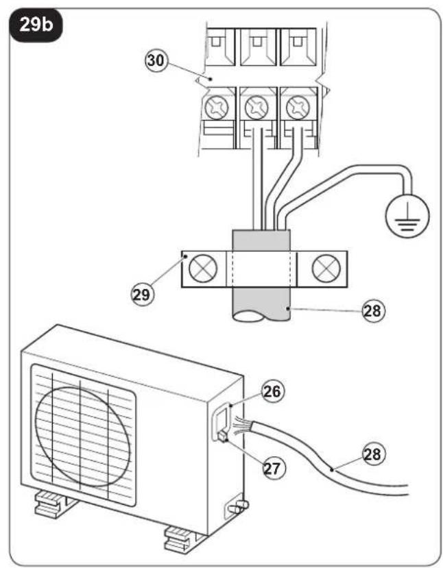
text_image
29b 30 29 28 26 27 28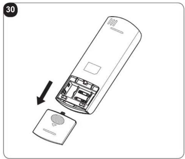
natural_image
Diagram of a remote control casing with an open lid and internal components, showing a directional arrow indicating assembly (no text or symbols present)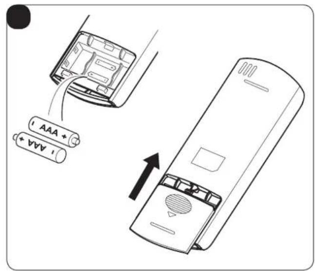
text_image
AAA + AAA +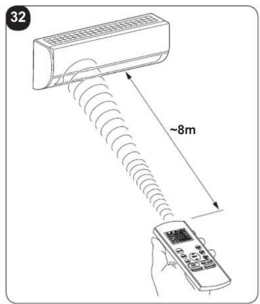
text_image
32 ~8m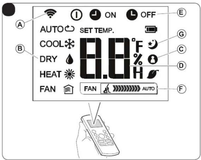
text_image
AUTO SET TEMP. COOL °F DRY % 0 HEAT H FAN AUTO A B C D E F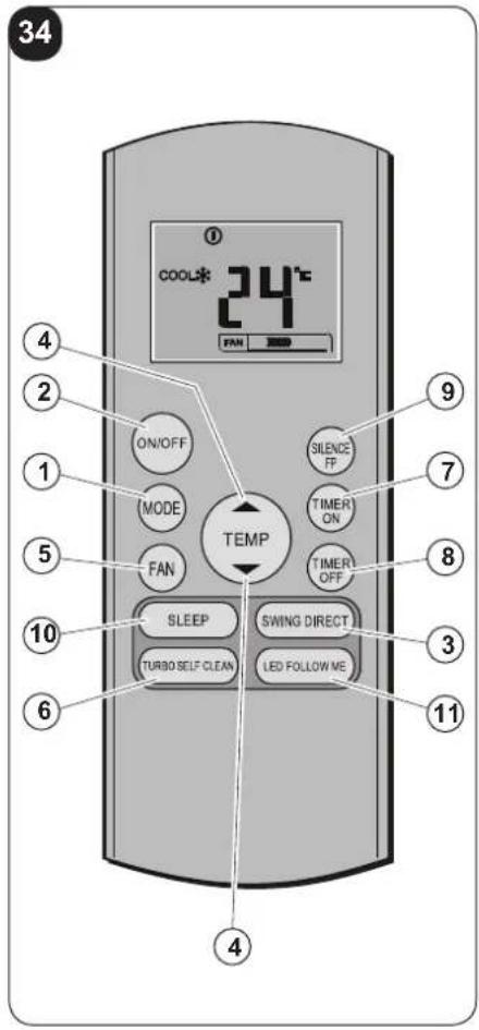
text_image
34 COOL* 24°C FAN 2020 ON/OFF MODE FAN TEMP SILENCE FP TIMER ON TIMER OFF SLEEP SWING DIRECT TURBO SELF CLEAN LED FOLLOW ME 4 2 1 5 8 7 9 3 6 11 4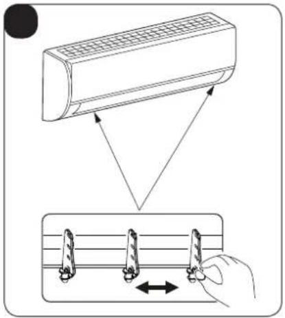
text_image
Diagram illustrating airflow or cooling process of an air conditioner, showing airflow direction and cooling mechanism with directional arrows.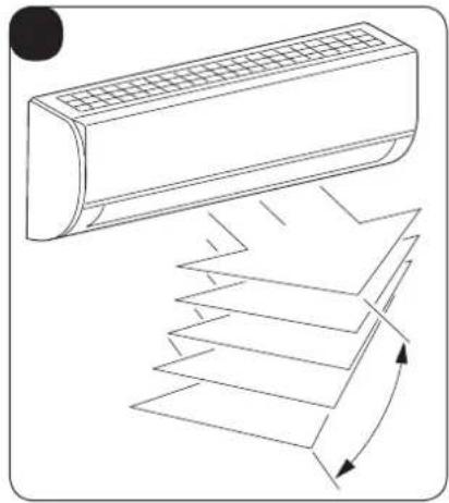
natural_image
Line drawing of a car air conditioner unit with airflow arrows indicating airflow direction (no text or symbols)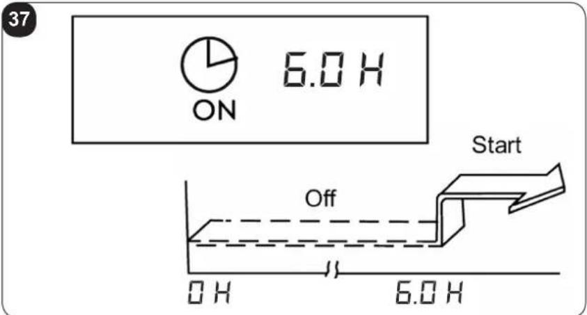
text_image
37 ON 6.0 H Start Off OH 6.0 H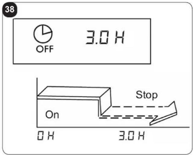
text_image
38 OFF 3.0 H On Stop 0 H 3.0 H
text_image
ON OFF 3.0 H 10.0 H Start Stop On 0 H 20 PM 3.0 H 23 PM 10.0 H 6 AM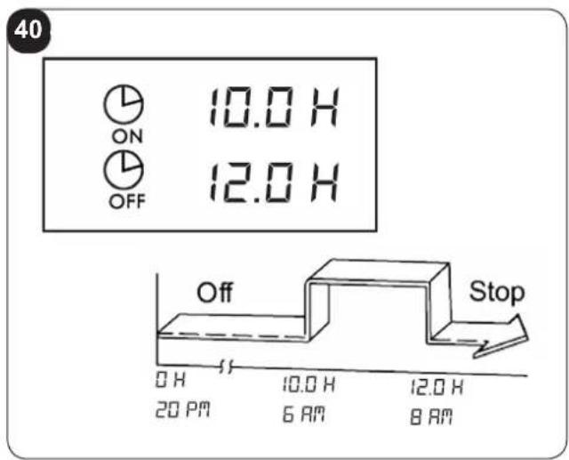
text_image
40 ON OFF 10.0 H 12.0 H Off Stop 0 H 20 PM 10.0 H 6 AM 12.0 H 8 AM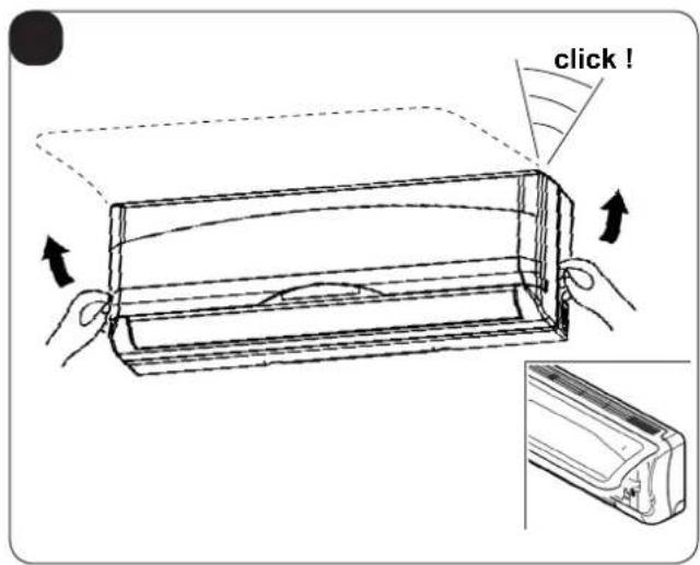
text_image
click !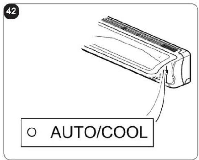
text_image
42 AUTO/COOL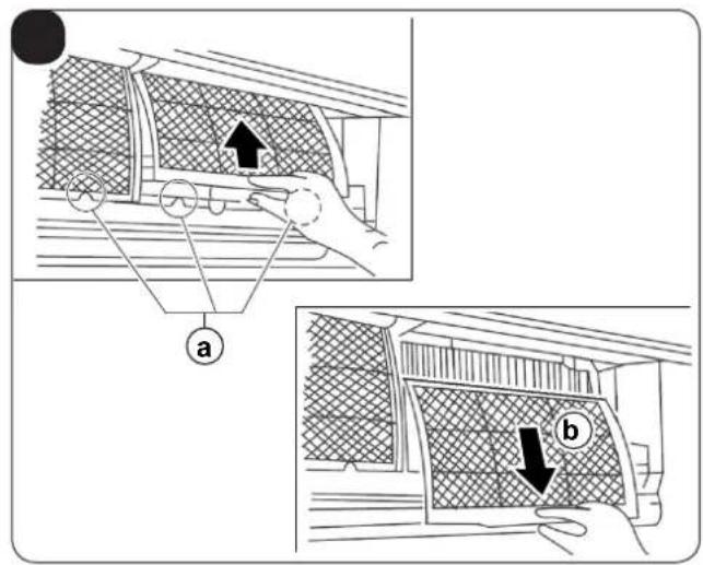
text_image
Diagram illustrating vehicle safety inspection steps with labeled components a and b, showing hand positioning and structural details.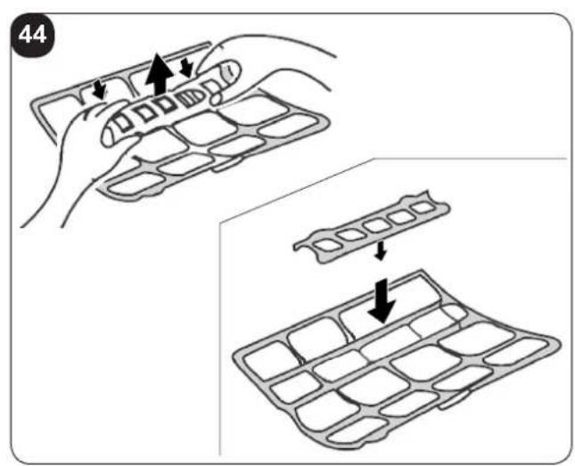
text_image
44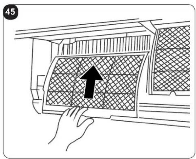
text_image
45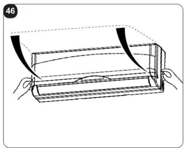
natural_image
Line drawing of a wooden tray with curved bands and a handle, no text or symbols present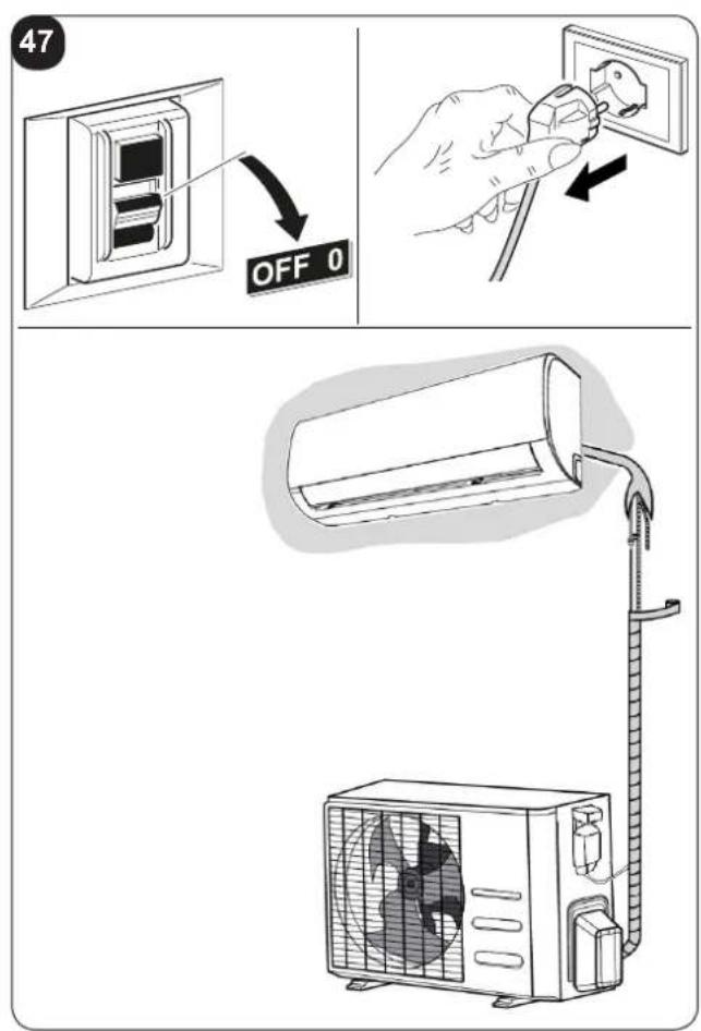
text_image
47 OFF 0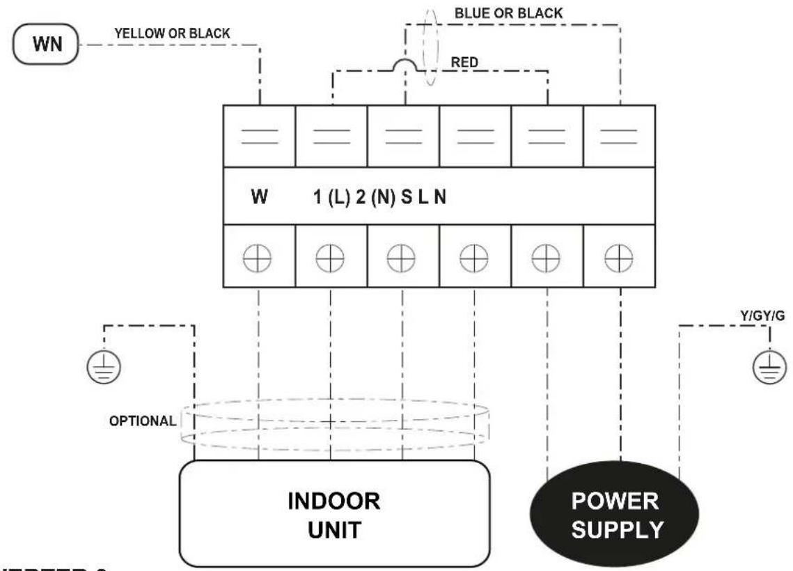
flowchart
graph TD
    A["WN"] --> B["1 (L) 2 (N) S L N"]
    B --> C["INDOOR UNIT"]
    C --> D["POWER SUPPLY"]
    D --> E["Y/GY/G"]
    F["OPTIONAL"] --> C
    G["RED"] --> B
    H["BLUE OR BLACK"] --> B
    I["YELLOW OR BLACK"] --> B
INVERTER 9
INVERTER 12
PAGINA INTENZIONALMENTE BIANCA PAGE INTENTIONALLY LEFT BLANK PAGE INTENTIONNELLEMENT BLANCHE DIESE SEITE WURDE ABSICHTLICH WEISS GELASSEN PÁGINA INTENCIONADAMENTE BLANCA PÁGINA INTENCIONALMENTE EM ABERTO PAGINA IS OPZETTELIJK LEEG GELATEN
INDICE GENERALE
0 -AVVERTENZE 3
0.1 - INFORMAZIONI GENERALI....3
0.2 - SIMBOLOGIA....3
0.2.1 - Pittogrammi redazionali....3
0.3 - AVVERTENZE GENERALI 5
0.4 - NOTE SUI GAS FLUORURATI 8
0.5 - USO PREVISTO 8
0.6 - ZONE DI RISCHIO....8
1 -DESCRIZIONE APPARECCHIO 9
1.1 - ELENCO COMPONENTI FORNITI A CORREDO 9
1.2 - MATERIALE NECESSARIO NON FORNITO A CORREDO 9
1.3 - IMMAGAZZINAMENTO 10
1.4 - RICEVIMENTO E DISIMBALLO 10
INFORMAZIONI RISERVATE AL "TECNICO INSTALLATORE"
text_image
Diagram showing airflow or ventilation system with a car air conditioner and a cylindrical device, labeled with point A and X1.text_image
401mm 229mm 228mm 126mm 42mm Ø 65mm Ø 65mm 47mm 58mmIT - 15
text_image
340mm IN IN OUT 514mm
text_image
A = ① kg B = ② kg A + B = ③ kg
text_image
Diagram showing a house connected to a pump system with labeled components A and B
text_image
Line drawing of a remote control device with labeled buttons and display screen3.1.1 - Inserimento delle batterie
text_image
Diagram of a household air conditioner unit with numbered parts and a hand holding a remote control.
1 -DESCRIPTION OF THE APPLIANCE 9
1.1 - LIST OF THE COMPONENTS SUPPLIED 9
1.2 - MATERIAL NECESSARY NOT SUPPLIED 9
1.3 - STORAGE....10
1.4 - RECEIPT AND UNPACKING 10
INFORMATION RESERVED FOR THE "INSTALLATION TECHNICIAN"
2 - INSTALLATION .... 10
2.1 - INSTRUCTIONS FOR INSTALLATION....10
2.1.1 - Minimum room area in the case of 11
2.2 - CHECKS TO PERFORM BEFORE INSTALLATION....11
2.3 - DATA TABLE 13
2.4 - SELECTION OF POSITION OF THE INSIDE UNIT 14
2.5 - INSTALLATION OF THE INSIDE UNIT 15
2.5.1 - Installation of fastening plate....15
2.5.2 - Realisation of pipe passage holes....15
2.5.3 - Piping connection....16
2.5.4 - Drain pipe connection....16
2.5.5 - Piping and protection wrapping connection....16
2.6 - SELECTION OF POSITION FOR OUTSIDE UNIT 17
2.6.1 - Heat pump appliances....18
2.6.2 - Outdoor unit assembly 18
2.6.3 - Execution, installation and connection of the refrigeration lines ..... 19
2.6.4 - Tests and inspection....20
2.6.5 - Plant vacuum....21
2.6.6 - Filling the plant 21
2.6.7 - Connection of the condensate drain line....22
2.7 - ELECTRIC CONNECTIONS....23
2.7.1 - Electric connection between indoor and outdoor units....23
2.7.2 - Indoor unit electric connection....23
2.7.3 - Outdoor unit electric connection....23
2.7.4 - Electric connection 24
2.7.5 - Delivery of the system....24
SECTION FOR THE TECHNICIAN AND USER
3 - USE AND MAINTENANCE.... 25
3.1 - USE OF THE REMOTE CONTROL....25
3.1.1 - Insertion of batteries....25
3.1.2 - Replacement of batteries 25
3.1.3 - Location of the remote controller....26
3.2 - COMPONENTS OF THE SYSTEM....26
EN - 1
3.3 - FUNCTION INDICATOR ON INDOOR UNIT DISPLAY PANEL....27
3.3.1 - Function Codes 27
3.4 - DESCRIPTION OF REMOTE CONTROL....27
3.4.1 - Indicators on remote controller 27
3.4.2 - Description of the remote control keys....28
3.4.3 - Follow Me function 28
3.4.4 - TURBO function 29
3.4.5 - SELF CLEAN function....29
3.4.6 - SILENCE function ......29
3.4.7 - FP function .....29
3.4.8 - TIMER keys....29
3.4.9 - SILENCE/FP key....29
3.4.10 - SLEEP key 29
3.4.11 - LED/FOLLOW ME key 30
3.4.12 - Automatic operation 30
3.4.13 - Functioning in Cooling/Heating/Fan only mode 30
3.5 - ADJUSTING AIR FLOW DIRECTION 31
3.5.1 - Adjustment of the vertical direction of the air (high - low) 31
3.6- DEHUMIDIFICATION....32
3.7.1 - Switch-on timer setting from the remote control....32
3.7.2 - Switch-off timer setting from the remote control....33
3.7.3 - Setting combined timer....33
3.8 - MANUAL OPERATION....34
4 - MAINTENANCE AND CLEANING 34
4.1 - CLEANING....34
4.1.1 - Cleaning the indoor unit and remote controller 34
4.1.2 - Cleaning the air filter 35
4.2 - MAINTENANCE 35
4.2.1 - Recommendations for energy savings 36
4.3 - FUNCTIONAL ASPECTS NOT TO BE MISTAKEN FOR ANOMALIES 36
4.4 - TROUBLESHOOTING 38
4.4.1 - Malfunctioning ....38
5 - GENERAL TROUBLESHOOTING 39
5.1 - ERROR DISPLAY (INDOOR UNIT) 39
5.2 - OTHER ERROR....40
6 - TECHNICAL DATA....40
This symbol on the product or its packaging indicates that the appliance cannot be treated as normal domestic trash, but must be handed in at a collection point for recycling electric and electronic appliances.
Your contribution to the correct disposal of this product protects the environment and the health of your fellow men. Health and the environment are endangered by incorrect disposal.
Further information about the recycling of this product can be obtained from your local town hall, your refuse collection service, or in the store at which you bought the product.
This regulation is valid only in EU member states.
EN - 2
ILLUSTRATIONS
The illustrations are grouped on the initial pages of the manual
MAIN INDEX
The main index of this manual is given on page "EN-1"
text_image
Index0 - WARNINGS
0.1 - GENERAL INFORMATION
First of all, we would like to thank you for choosing our appliance.
This document is confidential pursuant to the law and may not be reproduced or transferred to third parties without the explicit authorisation of the manufacturer. The appliance may undergo updates and therefore have details different from those represented, without prejudice to the texts contained in this manual.
0.2 - SYMBOLS
The pictograms in the next chapter provide the necessary information for correct, safe use of the machine in a rapid, unmistakable way.
0.2.1 - Editorial pictograms

Service
Refers to situations in which you should inform the SERVICE department in the company: CUSTOMER TECHNICAL SERVICE.

Index
Paragraphs marked with this symbol contain very important information and recommendations, particularly as regards safety.
Failure to comply with them may result in:
- danger of injury to the operators
- loss of the warranty
- refusal of liability by the manufacturer.

Raised hand
Refers to actions that absolutely must not be performed.

HAZARD
cates that the appliance uses inflammable refrigerant. If the refrigerant escapes and is exposed to a source of external ignition, there is a fire risk.
s to the personnel that the operation described could cause electrocution if not performed according to the safety rules.

GENERIC DANGER
It informs the personnel concerned that if the operation is not carried out in compliance with the safety regulations, it presents the risk of suffering physical damage.

DANGER DUE TO HEAT
It informs the personnel concerned that if the operation is not carried out in compliance with the safety regulations, it presents the risk of burns due to contact with components at very high temperatures.

DO NOT COVER
cates to the personnel concerned, that it is prohibited to cover the appliance, to prevent over-heating.

ATTENTION
dicates that this document must be read carefully before installing and/or using the appliance.
- Indicates that the assistance personnel must handle the appliance following the installation manual.

ATTENTION
dicates that there may be additional information in attached manuals.
- Indicates that information is available in the user manual or in the installation manual.
ATTENTION
Indicates that the assistance personnel must handle the appliance following the installation manual.
EN - 4
0.3 - GENERAL WARNINGS
WHEN USING ELECTRICAL EQUIPMENT, BASIC SAFETY PRECAUTIONS MUST ALWAYS BE FOLLOWED IN ORDER TO REDUCE RISKS OF FIRE, ELECTRIC SHOCKS AND INJURY, INCLUDING THE FOLLOWING:

- This document is restricted in use to the terms of the law and may not be copied or transferred to third parties without the express authorization of the manufacturer, OLIMPIA SPLENDID.
Our machines are subject to change and some parts may appear different from the ones shown here, without this affecting the text of the manual in any way.
-
Read this manual carefully before performing any operation (installation, maintenance, use) and follow the instructions contained in each chapter.
-
Make all personnel involved in transport and installation of the machine aware of these instructions.
-
THE MANUFACTURER IS NOT RESPONSIBLE FOR DAMAGES TO PERSONS OR PROPERTY CAUSED BY FAILURE TO FOLLOW THE INSTRUCTIONS IN THIS MANUAL.
-
The manufacturer reserves the right to make any changes it deems advisable to its models, although the essential features described in this manual remain the same.

-
The installation and maintenance of air-conditioners like this one may be hazardous as they contain a cooling gas under pressure as well as powered parts. Therefore, the installation, first startup and subsequent maintenance should be carried out exclusively by authorized, qualified personnel.
-
Failing to comply with the instructions contained in this manual, and using the unit with temperatures exceeding the permissible temperature range will invalidate the warranty.
-
Routine maintenance of the filters and general external cleaning can be done by the user as these operations are not difficult or dangerous.
- During installation and maintenance, respect the precautions indicated in the manual, and on the labels applied inside the units, as well as all the precautions suggested by good sense and by the safety regulations in effect in your country.


- Perform installation and maintenance using equipment that is suitable for inflammable gas.

- Always wear gloves and protective goggles when performing any operations on the refrigerating side of the units.

- Air conditioners must not be installed in places containing inflammable gasses, explosive gasses, or in very humid environments (laundries, greenhouses, etc.), or in places where there are machines that generate very great heat.

- In case of replacement of parts, use only original OLIMPIA SPLENDID parts.

- IMPORTANT! prevent any risk of electrocution, always disconnect the main circuit breaker before making electric connections or performing any maintenance on the units.

- Lightening, cars in the vicinity and mobile phones can cause malfunctioning. Disconnect the unit electrically for a few seconds and then re-start the air conditioner.

- On rainy days, it is recommended to connect the electric power supply in order to prevent damage caused by lightening.

- If the unit is unused for a long period, or no-one uses the climate-controlled room, it is recommended to disconnect the electric power supply in order to prevent accidents.

- Do not use liquid or corrosive detergents to clean the unit, do not spray water or other liquids onto the unit, since they could damage the plastic components or even cause electric shocks.

- Do not wet the indoor unit and the remote control. Short circuits or fires may occur.

- In the event of operating anomalies (e.g. strange noise, bad odour, smoke, abnormal temperature rise, electric dispersions, etc.) disconnect the electric power supply immediately.
Contact the local dealer.
- Do not let the air conditioner run for a long time when the humidity is very high and a door or a windows is left open.
Moisture may condense and wet or damage furniture.
- Do not plug or unplug the power supply plug during operation. and electric shocks risk.
SPLENDID
- Do not touch (operation) the product with wet hands and electric shocks risk.

- Do not place a heater or other appliance near the power cable. Fire and electric shocks risk.

- Make sure water does not enter the electrical parts. could cause fires, product failure or electric shocks.

- Do not open the air inlet grid during appliance operation. Risk of injury, electric shock or damage to the product.

- Do not block the air inlet or outlet; the product could be damaged.

- Do not insert hands or other object through air inlet or outlet while the product is operated.
The presence of sharp and moving parts could cause injury.
- Do not drink the water drained from the product. It is not sanitary could cause serious health issues.

-
When there are gas leaks from other units, ventilate the room well before activating the air conditioner.
-
Do not disassemble or modify unit.
-
Ventilate the room well when used together with a stove, etc.
-
Do not use for special purposes.
-
The persons that work or intervene on a cooling circuit, must be in possession of suitable certification, issued by an accredited assessment body. This must attest skill in safely handling refrigerants in compliance with assessment specification acknowledged by sector associations.
-
Do not emit R32 gas into the atmosphere; R32 is a fluorinated greenhouse gas with a Global Warming Potential (GWP) = 675.

- The appliances described in this manual are in compliance with the applicable European Directives and successive amendments.

- The appliance contains A2L inflammable gas. the correct method of installation, see paragraph "2.1".

0.4 - NOTES REGARDING FLUORINATED GASES

• This climate control appliance contains fluorinated gas.
or specific information regarding the type and quantity of gas, refer to the data plate affixed to the unit.

the installation, assistance, maintenance and repair of the appliance, must be performed by a qualified certified technician.
- Product removal and re-cycling operations must be performed by a qualified certified technician.
- If the system has a leak-detection device installed, the checks for leaks must be performed at least every 12 months.
- When the unit is checked for leaks, keeping a record of all inspections is highly recommended.
0.5 - PROPER USE
- The air-conditioner should be used for the exclusive purpose of producing hot or cool air (on demand) for the sole purpose of obtaining a comfortable temperature in the room.
- Improper use of the machine (outside and inside units) causing damage to persons, property or animals relieve OLIMPIA SPLENDID of any liability.
0.6 - HAZARDOUS ZONES
- The climate controllers must not be installed in environments with the presence of inflammable gases, explosive gases, in very humid environments (laundries, greenhouses, etc.), or in places with other machines that generate a strong heat source, in proximity of a sources of salt water or sulphurous water.

- DO NOT use gas, gasoline or other inflammable liquids near to the climate controller.
- The climate controller does not have a fan for the introduction of fresh outdoor air into the room; ventilate by opening doors and windows.

• Always install circuit breaker and a dedicated power circuit.
This product must be used exclusively according to the specifications indicated in this manual. Use different to that specified, could cause serious injuries.
THE MANUFACTURER IS NOT LIABLE FOR INJURY/DAMAGE TO PERSONS/OBJECTS DERIVING FROM FAILURE TO COMPLY WITH THE REGULATIONS CONTAINED IN THIS MANUAL.
EN - 8
1 - DESCRIPTION OF THE APPLIANCE
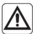
1.1 - LIST OF THE COMPONENTS SUPPLIED
The units making up the climate control system are packaged individually in cardboard boxes.
Individual unit packages can be transported by hand by two members of personnel, or loaded onto a transport trolley; up to max. three packages stacked for indoor units and individually for outdoor units.

The parts indicated below are included in the supply. The other items necessary for installation must be purchased.
- Outdoor unit quantity 1
- Indoor unit quantity from 1 to 5 (according to the model)
- Plate fixing screw
- Plugs
- Condensate drain fitting quantity 1
-
Gasket quantity 1
-
Indoor unit fixing plate quantity 1 for each indoor unit
- Remote control quantity 1
- Battery for remote control quantity 2 - AAA type x 1.5V
- Instruction booklet quantity 1
text_image
A 1 2 3 4 5 6 7 8 9 10 OLYAS PRO E INVERTER 9 INVERTER 121.2 - MATERIAL NECESSARY NOT SUPPLIED
For correct installation of the appliance, components that have not been supplied must be used.
a. Connection pipes unit (water side)
b. Connection pipes unit (gas side)
c. Adapter fitting (one for each indoor unit)
1.3 - STORAGE
Store the cartons in a closed environment protected against atmospheric agents and raised off the floor by planks or a pallet.

TO NOT TURN THE CARTON UPSIDE DOWN.
1.4 - RECEIPT AND UNPACKING
The packaging is made up from suitable material and performed by expert personnel.
The units are delivered complete and in perfect condition. However, for he quality control of the transport services, follow the warnings below:
a. On receipt of the packages, check whether the packaging is damaged. If this is the case, withdraw the goods with reserve, producing photographic proof and any apparent damage.
b. Unpack, checking the presence of the individual components with the packing lists.
c. Control that all components have not undergone damage during transport. If this is the case, inform the carrier by registered letter with acknowledgement of receipt within 3 days of receiving the goods, presenting photographic documentation.
d. Pay attention when unpacking and installing the equipment.
Sharp parts can cause injury. Pay particular attention to the edges of the structure and the fins of the condenser and evaporator.
e. Send the same information by fax also to OLIMPIA SPLENDID.

No information concerning damage undergone can be taken into consideration after 3 days from delivery.
For any controversy the court of jurisdiction will be BRESCIA.

Keep the packaging for at least the duration of the warranty period, for any shipments to the after-sales centre for repairs. Dispose of packaging in compliance with the regulations in force regarding waste disposal.
2 - INSTALLATION
2.1 - INSTRUCTIONS FOR INSTALLATION
To obtain the best results and optimum performance, follow the instructions for correct installation provided in this manual.


The appliance contains A2L inflammable gas.


The appliance must be installed, activated and kept in an environment with area exceeding X m ^2 (see table at the side).
The appliance must not be installed in a non-ventilated area, whenever the surface is less than X m ^2 (see table at the side).

Failure to apply the regulations indicated, which can cause unit malfunctioning, relieve OLIMPIA SPLENDID from any form of warranty and any damage/injury caused to persons, animals or objects.

The electrical system must comply with the regulations and rating data in the technical sheet, with good grounding.
EN - 10

OLIMPIA SPLENDID

Do not install, remove, or reinstall the unit by yourself (customer).
ere is risk of fire, electric shock, explosion, or injury.

For installation, always contact the dealer or an Authorized service center.
ere is risk of fire, electric shock, explosion, or injury.

Be sure the installation area does not deteriorate with age.
e base collapses, the air conditioner could fall with it, causing property da mage, product failure, and personal injury.

Install the unit securely in a place which can bear the weight of the unit.

Do not install the unit in a place where a flammable gas leaks.
2.1.1 - Minimum room area in the case of
| Model | Quantity of refrigerant gas (kg) | Height of installation (m) | Minimum room area (m2) |
| Refrigerant gas load as per technical data label (without additional load) | |||
| MONO | 0,87 1,8 2 | ||
| 0,87 0,6 7 | |||
| Refrigerant gas load with MID additional load | |||
| MONO | 1,03 1,8 2 | ||
| 1,03 0,6 10 | |||
| Refrigerant gas load with MAXIMUM additional load | |||
| MONO | 1,17 1,8 2 | ||
| 1,17 0,6 12 | |||
2.2 - CHECKS TO PERFORM BEFORE INSTALLATION
a. Checks at the area
Before starting to work on the systems containing inflammable refrigerants, safety checks are necessary to reduce the risk of ignition to a minimum.
To repair a refrigeration system, the following precautions must be complied with before working on the system.
b. Work procedure
The job must be performed according to a controlled procedure in a way to reduce the risk of the presence of inflammable gas or vapour to a minimum during performance of the job.
c. General work area
All maintenance personnel and those working in the local area, must be trained regarding the job performed.
Do not work in tight spaces.
EN - 11
The area around the work area must be isolated.
Guarantee that the conditions inside the area are safe by verifying the inflammable material.
d. Check the presence of refrigerant
The area must be controlled with a specific refrigerant detector before and during the performance of the job, in a way to guarantee that the technician is informed regarding the presence of potentially inflammable atmospheres.
Check the leak detector equipment used is suitable for use with inflammable refrigerants, i.e. does not cause sparks, is suitably sealed or intrinsically safe.
e. Presence of extinguishers
Whenever work must be performed on the refrigeration system at high temperatures or on relative components, a suitable fire-prevention system must be prepared.
Position CO2 or dry powder extinguishers in proximity of the loading area.
f. No source of ignition
No-one working in the refrigeration systems and exposed to contact with the piping that contains or contained inflammable refrigerant, must use sources of ignition in order to prevent the risk of fire or explosion.
Every possible source of ignition, among which cigarette smoke, must be kept at a due distance from the place of installation, repair, removal or disposal, where there is a risk of the refrigerant liquid leaking into the surrounding space.
Before performing the job, the area surrounding the appliance must be controlled in order to ascertain that there are no inflammable substances or risks of ignition present.
NO SMOKING signs must be displayed.
g. Ventilated area
Make sure that the area is open or suitably ventilated before interacting with the system or performing any operation at high temperatures.
Ensure constant ventilation during the operations period.
Ventilation must safely disperse all refrigerant released and, if possible, expel it outside into the atmosphere.
h. Refrigeration system checks
If modified, the electric components must be suitable for the purpose and compliant with the correct specifications.
Always follow the manufacturer's guide lines relative to maintenance and technical after-sales assistance. If in doubt, consult the manufacturer's technical after-sales service.
The plants that use inflammable refrigerants must be subjected to the following verifications:
- the dimension of the load must be compliant with the chamber in which the components containing the refrigerant are installed;
- the plants and ventilation outlets must operate adequately and not be obstructed;
- if an indirect refrigeration circuit is in use, check the presence of refrigerant in the secondary circuit; the marking on the systems must be visible and legible;
EN - 12
- illegible markings and signs must be corrected;
- the pipe or refrigeration components must be installed in a position where it is improbable that they are exposed to substances that could corrode the components containing the refrigerant, unless the components are manufactured with intrinsically corrosion resistant materials or are appropriately protected from corrosive agents.
i. Check the electric devices
The repair and maintenance interventions of electric components must envision initial safety checks and component inspection procedures.
In the case of a fault which may compromise safety, no electric power supply must be connected to the circuit until it has been suitably repaired.
If the fault cannot be repaired immediately, but the operation must be continued, use a suitable temporary solution.
This solution must be communicated to the owner of the plant so that all parties can be informed.
The initial safety controls envision:
- draining the condensers: this operation must be performed safely to prevent the possible formation of sparks;
- no exposure of components and electric wiring to voltages during loading, repair or purification of the system;
• the continuity of the earth.
I. Repair interventions of the hermetic components
- During the repair of hermetic components, all electric power supply lines must be disconnected from the appliance running, before the eventual removal of the hermetic covers, etc.
Whenever it is absolutely necessary to have electric power supply for the unit during maintenance, a constantly active leak detector must be positioned in the most critical point in order to signal a potentially dangerous situation.
- Particular attention must be paid to the following to guarantee that, in the case of intervention on electric components, the housing is not altered in a way to affect the level of protection.
This includes damage to cables, excessive number of connections, terminals not manufactured in compliance with original specifications, damage to the gaskets, incorrect installation of the closing devices, etc.
• Make sure that the appliances are mounted securely.
- Make sure that the gaskets or sealing materials have not deteriorated to the point that they cannot be used to prevent the entry of inflammable atmospheres. The spare components must be compliant with manufacturer specifications.

The use of silicone-based sealants can inhibit the efficacy of some types of leak detection equipment.
Intrinsically safe components do not have to be isolated before working on them.
2.3 - DATA TABLE
According to configuration of the unit, the data given in the table on page 15 must be checked.
2.4 - SELECTION OF POSITION OF THE INSIDE UNIT
To obtain the best operating performance and prevent faults or hazardous conditions, the position of indoor unit installation must meet the following requirements:
a. Do not expose the indoor unit to heat or steam.
b. Make sure that the space to the right and left is at least 120 mm and space above the unit is at least 150 mm. (figure 1).
c. The indoor unit must be installed at a minimum height of 2 metres and maximum of 3 metres from the floor.
d. The wall where the indoor unit is to be fixed, must be stable, strong and suitable to support the weight.
e. There must be no obstacles for the free circulation of air both from the inlet side and especially the outlet side. In particular, there must be no obstacles within a distance of 2000 mm.
A shorter distance could cause turbulence such to prevent correct operation of the appliance.
f. If possible, install the unit on an outdoor wall, in a way to be able to convey condensate draining to the outside.
g. The indoor unit must not be in a position such that the air flow is aimed directly at the persons below (figure 3).
Table 17
| Model | |
| Length for one indoor unit | max 25 m. |
| Difference in height between the indoor and outdoor units “A” | max 10 m. |

text_image
X1 Ah. The indoor unit must not be installed directly above household appliances (television, radio, refrigerator, etc.) or above a heat source (figure 2).
i. Install the indoor unit in a way that there are no obstacles, which do not allow the signals emitted by the remote control to be received (figure 4).
EN - 14
2.5 - INSTALLATION OF THE INSIDE UNIT
2.5.1 - Installation of fastening plate
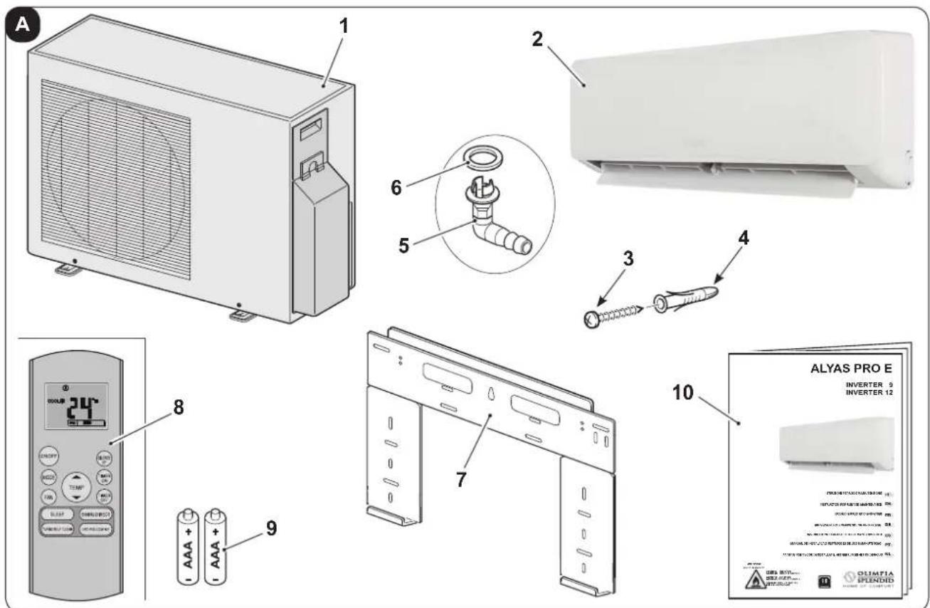
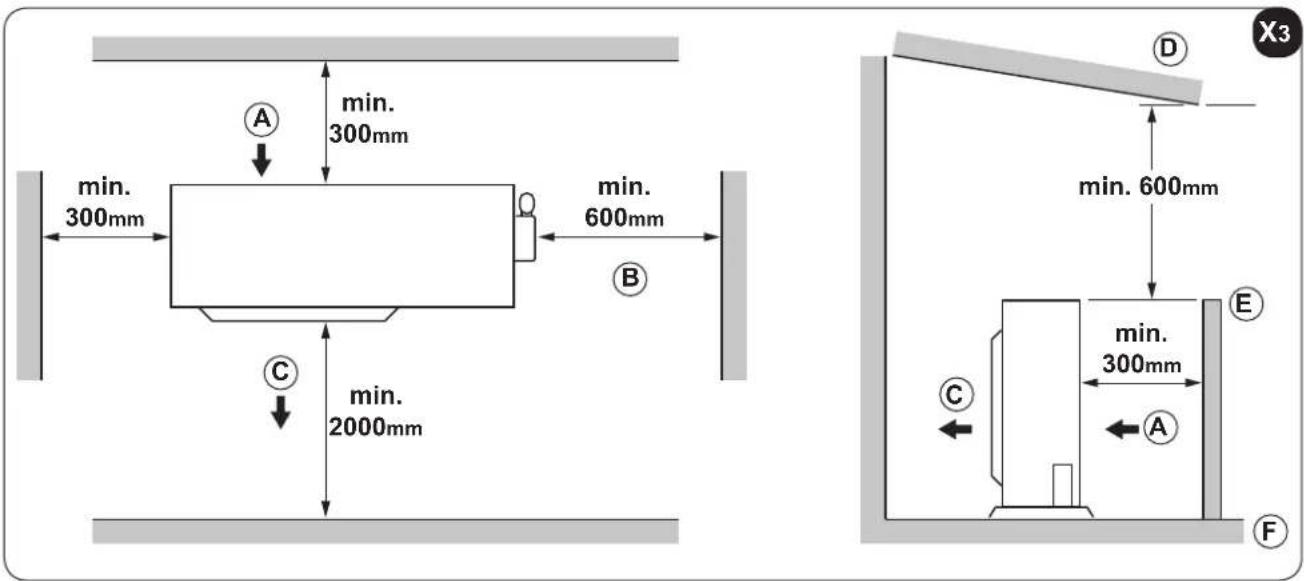
After having checked that described in paragraph "2.2" and on the previous page (figure X1), assemble the fixing plate (7) taking the dimensions stated in figure X2 into consideration.
a. Position the plate against the wall.
b. Mark the drilling points, making sure that they are level.
c. Make the holes necessary in the wall using a suitable bit.

Make sure there are no pipes or electric ducts in the drilling area.
d. Insert the plugs (4) into the holes and fix the plate (7) to the wall using the screws (3) supplied (figure 5).

Using a spirit level, make sure that the fixing plate (7) is level.
e. If the wall is in wood, use relevant countersunk-head screws (not supplied).
f. Check the stability of the plate (7), moving it laterally and vertically.
2.5.2 - Realisation of pipe passage holes
If the connection lines arrive from the rear right of the indoor unit, a hole "R" must be made for passage of the piping, as successively described (see figure X2).
a. Make a 8÷10 mm hole in the centre of the position "R", with slope towards the outdoors of 5% (to allow condensate to be drained correctly (figure 6).
b. Make the hole "R" using a core drill with the diameter indicated in the table of figure X2.
c. Insert the drain line piping and that of refrigeration into the hole along with the electric connection cable.
If the connection lines arrive from the rear left of the indoor unit, a hole "L" must be made for passage of the piping (see figure X2).

fixing bracket
indoor unit
text_image
401mm 229mm 228mm 126mm 42mm Ø 65mm Ø 65mm 47mm 58mmEN - 15
2.5.3 - Piping connection (figure 7)
For the left (C) and right (F) piping, remove the respective pipe covering (B or G) from the lateral panel.

It is recommended to keep the pipe covering that has been removed, since it can be re-used if the air conditioner is installed in another position.
For the rear right (E) and rear left (D) piping, install the pipes as illustrated in figure 7.
Bend the connection pipe, which must be laid at a max. distance of 43 mm from the outside wall.
Fix the end of the connection pipe (I). (see "Execution, installation and connection of the refrigeration lines").
Key (figure 7)
A Pipe-holder
B Pipe protection (left)
C Left piping
D Left rear piping
E Right rear piping
F Right piping
G Pipe protection (right)
H Indoor unit outlet
I Connection pipe
L Upper hook
M Lower hook
N Cladding material
a. Attach the upper bracket present in the rear part of the indoor unit to the upper hook of the fixing bracket (pos. 7 - figure 8).
b. Move the unit laterally to ensure it is correctly attached to the fixing hook (7).
c. Piping connection is easily performed by lifting the indoor unit and introducing cladding between the same and the wall.
Remove the cladding once connection has been completed.
d. Push the lower part of the indoor unit towards the wall to attach it to the fixing bracket (pos. 7 - figure 8).
e. Try and move the indoor unit laterally and vertically to make sure that it is attached securely.
2.5.4 - Drain pipe connection (figure 9)
a. Insert the drain pipe (A), making sure that it slopes downwards.
b. If necessary, connect an extension (C) to the drain pipe, isolate the joint with a protection pipe (B).
2.5.5 - Piping and protection wrapping connection (figure 10)
Evenly wrap the connection cable, drain pipe and electric cables with electrical tape, as illustrated in figure 10.

Given that the condensate water from the rear of the indoor water is collected in the "Pond Box" tray and taken out of the compartment, do not put anything in the tray.
Key (figure 10)
A Collection tray
B Piping compartment
C Electrician's tape
D Connection pipe
E Connection cable
F Drain pipe
EN - 16
2.6 - SELECTION OF POSITION FOR OUTSIDE UNIT
To obtain the best operating performance and prevent faults or hazardous conditions, the position of outdoor unit installation must meet the following requirements:
a. It should be protected from direct sunlight (fig. 11).
b. It should be protected from atmospheric agents (rain, snow) and from direct gusts of strong wind (fig. 11).
c. It should also be protected from any copious downflow of water (gutter drains or watering cans) (fig. 12).
d. It should stand on a solid surface able to withstand its weight (fig. 12).
e. The outside unit must be installed perfectly level (check with a bubble level).
Note: If the outdoor unit must be installed on the wall or roof, it is necessary to use the relevant kit (optional)

For assembly, follow the relative instructions, attached to the kit packaging, scrupulously.
f. The unit must not be in a position that obstructs the passage of persons or animals.
g. The unit should not be installed downwind of chimneys discharging burnt gas or subject to emissions of fumes, oily or corrosive gasses.
h. It should be possible to discharge the condensation produced.
i. Take the air conditioner weight into account and select a place where noise and vibration will not be an issue.
I. Select a place so that the warm air and noise from the air conditioner do not disturb neighbors.
m. Zones with probable accumulation of snow (figure 13).
Position the outdoor unit on a raised surface (wall), with height above the foreseeable maximum amount of snowfall, since:
- if the appliance does not have a heat pump, when the snow melts, water may infiltrate inside the unit and cause damage to the electric components.
- if the appliance has a heat pump, the accumulation of snow prevents the regular circulation of the air and makes condensate drainage difficult.
n. Positioning the unit on a floor area (terrace, land, roof, etc.) in areas that are difficult to access.
The support base must have good drainage of the water and prevent the possible accumulation of dirt under the unit, (e.g. dry leaves - figure 13).
In this case, make a raised area of 10 ÷ 15 cm onto which the unit can be fixed using foundation studs.
No interventions are required when positioned on a balcony, since there is already enough slope for the regular run-off of the water and sufficient protection from the accumulation of dirt.
o. Positioning the unit on a rigid metal base (brackets, metal profile supports, etc.).
In this case, the unit must always be fastened to the support base via vibration dampers (figure 14) with dimensions and capacity suitable for the weight of the machine (on request).
Furthermore, the base must have appropriate rigidity to prevent the amplification of vibrations due to regular operation.
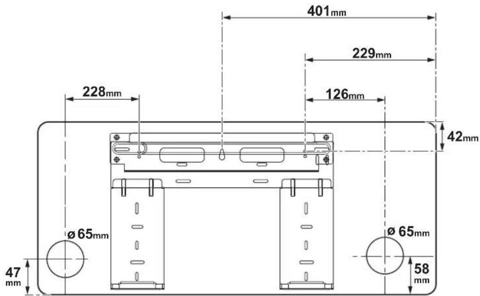
p. Make sure that there is the minimum space around the outdoor unit necessary to guarantee correct operation and the cleaning and maintenance interventions, as indicated in figure X3.
2.6.1 - Heat pump appliances.
- During operation in heating mode, condensate is produced in the outdoor unit due to defrosting, which must be able to run-off freely to prevent stagnation.
- When positioned on a flat surface, a draining channel must be created around the unit that goes directly into the rainwater collection well of the water network (figure 15).
- In the case of installation on a balcony or terrace, it must be possible to position a recipient under the unit, possibly in galvanised sheet or stainless steel (preferable), with drain pipe that flows directly into the gutter.
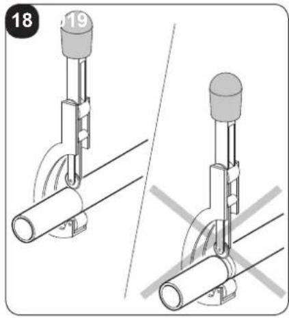
- Another option (figure 16) is to position the gasket (6) on the fitting (5) and then insert the latter into the hole made on the bottom of the outdoor unit and turn it by 90^ to fix it securely.
- Connect a rubber hose (not supplied) to the fitting (6) if water is drained from the outdoor unit in heating mode.
text_image
340mm IN IN OUT 514mmX4
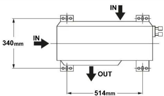
2.6.2 - Outdoor unit assembly
Proceed as follows (as described in the previous paragraph), once the ideal position for installation of the outdoor unit has been identified:
a. Position the unit on the support base, respecting the drilling distances indicated in the table in figure X4.
b. Screw any clamping nuts, without tightening completely.
c. Using a spirit level, check the unit is level; if necessary, adjust the support feet.
d. Tighten any clamping nuts correctly.
IN = air inlet - OUT = air outlet
EN - 18
e. If the outdoor unit is higher than the indoor units, to prevent rain entering, a downward bow must be made along the connection pipe (siphon) before the connection pipe enters the wall. This is to guarantee that the lowest point of the connection pipe is outdoors.
2.6.3 - Execution, installation and connection of the refrigeration lines

Do not make the connections using normal hydraulic piping, which could contain scrap residues, dirt or water, and which can damage the unit components and jeopardise correct operation of the appliance.

Only use copper piping, specific for refrigeration, which is supplied clean and sealed at the ends.

When the cuts have been made, seal the end of the roll and piece cut immediately. Insulated copper pipes can be used for refrigeration.
Only use pipes with diameters that reflect the dimensions described in the “Technical data” paragraph.
Identify the route of the piping in a way to reduce the length and bends as much as possible in order to obtain maximum system performance.

Performance is based on standard length and maximum length allowed. collectors for 5-7 metres must be installed (figure 17).
To establish whether the gas load needs to be topped-up, refer to the table below.
| Model | Gas pipeø | Liquid pipeø | Additional refrigerant g/m |
| 9-12 3/8 - 9,52 -1/4 | -6,35 12 |
Key (figure 17)
1 Indoor unit
2 Outdoor unit
3 Oil collector
- Max. elevation (see table 17 "A")
- Max. lengthù (see table 17)

The refrigerant should be charge from the service port on the outdoor unit's low pressure valve.

Piping connections must be outdoors.
a. Fasten a cable raceway to the wall (possibly with internal partitioning) of suitable size for the pipes and electric wires to pass through.
b. Cut the sections of pipe leaving an extra 3 ÷ 4 cm on the ends.

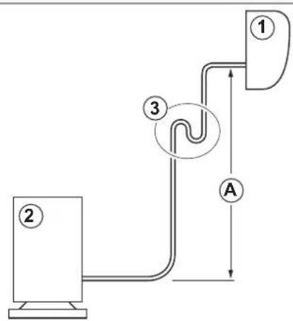
Use a wheel pipe cutter only to cut the pipes (fig. 18) clamping it in short lengths so as not to crush the pipe.
EN - 19
NEVER USE A NORMAL HANDSAW,
scraps could fall inside the pipe and enter the circuitry of the system, damaging the parts severely (fig. 19a).
c. Remove possible burrs with the special tool.

Immediately after cutting and deburring the pipes, seal the ends with insulating tape.
d. If you do not use preinsulated pipes, they must be insulated as follows:
• material: polyurethane foam with closed cells
- max. coefficient of transmission: 0,45 W/(K x m ^2 ) or 0.39 kcal/(h x C x m ^2 )
• minimum thickness: 6 mm (for liquid pipes)
• minimum thickness: 9 mm (for gas pipes)

Do not place both pipes in the same sheath, as this would jeopardize the proper operation of the system (fig. 19b).
e. Bind any joints in the sheath securely with insulating tape.
f. Insert the fixing nut into the pipe before performing flaring (figure 20).
g. Flare the pipe ends using the special tool. Take care not to break, crack or split the pipe (fig. 20).
h. Lubricate the connecting thread with oil for coolant.

DO NOT USE ANY OTHER TYPE OF LUBRICANT
i. Screw the pipe nut manually on the connecting thread.
I. Tighten the nut definitively using a wrench to hold the threaded part of the attachment still (to prevent deformations), and a dynamometric wrench on the nut (figure 21).
Calibrate the dynamometric wrench to the value suitable for the pipe dimensions.
| External diameter of the pipe | Coupling torque (N.cm) |
| 6,35 mm 0.25" | 18~20(180~200 kgf/cm) |
| 9,52 mm 0.375" | 32~39(320~390 kgf/cm) |
2.6.4 - Tests and inspection
After making all pipe connections, check the seal of the system.
Operate as follows:
a. Loosen the cap (20) on the gas line service fitting (figure 22).
b. Connect a tank of anhydrous nitrogen to the coupling with a 5/16" connector and a pressure reducer.
c. Open the tap on the tank and pressure reducer and bring the pressure in the circuit to 3 bar; close the tank.
d. If after about 3 minutes the pressure does not drop, the circuit is in good working order and the pressure can be raised to 15 bar by reopening the tank.
e. Check again after 3 minutes that the pressure remains stable at 15 bar.
f. For safety reasons apply a solution of soapy water to the connectors and check for the formation of bubbles revealing leakage of gas.
g. If the pressure should drop and the search on the attachments with soapy solution gives a negative outcome, introduce R32 gas into the circuit and look for the leak using a leak detector.
EN - 20
Since the circuit has no welding points, the leaks should only be present in the piping joints. In this case, tighten the nuts with greater force (figure 23), or make the attachments again with the relative flaring.
h. Repeat the seal test.
2.6.5 - Plant vacuum
When all of the tests and checks regarding perfect sealing have been performed, a vacuum must be applied to the system to remove the impurities contained therein (air, nitrogen and humidity).
a. Use a vacuum pump with capacity of 40 l/min (0.66 l/s) and connect it to the gas line service fitting using a flexible hose with 5/16" attachment.
b. Lower the pressure inside the circuit to the absolute value of 50 Pa for approx. 2 hours.

If, after this period of time, the pressure has not been taken to the set value (50 Pa), it means that there is a lot of humidity in the circuit or there is a leak.
c. Maintain the vacuum pump operating for another 3 hours.

If the value still hasn't been reached after this period of time, look for the leak.
d. When the vacuum has been applied and the system has been cleaned, remove the pump fitting when this is still running.
e. Tighten the cap (20) (figure 24).
2.6.6 - Filling the plant
Remove the cap in order to operate on the intake line cock and on that of the liquid which, on opening, allow the appliance to be filled with refrigerant.

- Look for an adhesive sheet with 2 stickers in the outdoor unit documentation.
- Remove the lower label and stick it in proximity of the loading and/or reset point.
- Clearly note the amount of refrigerant loaded on the refrigerant label using indelible ink.
- In box "1" note the amount of gas established in the technical data (kg).
- In box "2" note any additional load inserted by the installation technician (kg).
- In box "3" the sum of the two previous values (kg).
- B field additional refrigerant charge
- write out refrigerant amount A, B and A+B
text_image
A = ① kg B = ② kg B = ③ kg
text_image
Diagram showing a house connected to a pump system with labeled components A and B
- Remove the transparent label remaining in the upper part of the adhesive sheet and stick it over the previous one affixed to the loading point.

Avoid the emission of the fluorinated gas contained here.
Make sure that the fluorinated gas is never released into the atmosphere during installation, assistance and disposal.
- Whenever a fluorinated gas leak is detected, the leak must be found and repaired as quickly as possible.

ONLY qualified personnel must provide assistance on this product.

Any use of fluorinated gas in this appliance, e.g. during manual movement of the product or re-loading the gas, must be compliant with the regulations regarding determined fluorinated greenhouse gases and any applicable local laws.
2.6.7 - Connection of the condensate drain line
Connect a drain pipe, of appropriate length, to the indoor unit condensate drain pipe, and block it with a strap.
Make it run inside the duct parallel to the system pipes, fastening it to the same using straps.

Do not tighten the straps excessively in order to prevent damage to the insulation of the pipes and narrow the drain pipe.
Where possible, make the condensate liquid flow directly into a rainwater gutter.

If the drain pipe is fed into a sewage system, it is necessary to bend the pipe in order to create a siphon (figure 25), in order to avoid the diffusion of unpleasant odours into the environment.

The siphon bend must never be at a level below 1500 mm from the lower wire of the appliance (figure 25).

If draining is into a recipient (figure 26), this must never be closed so as not to prevent counter-pressures such to compromise the operation, and the pipe itself must never reach the level of the liquid deposited.

Check the correct run-off of the condensate liquid through the relative pipe by very slowly pouring approx. 1/2 litre of water into the collection tray of the indoor unit (figure 27).
EN - 22
2.7 - ELECTRIC CONNECTIONS
2.7.1 - Electric connection between indoor and outdoor units
The connection wiring diagrams are illustrated in figure 48.
The electric connection between the indoor units must have the features stated in the table of the following page.
The connection cable between the outdoor unit and the indoor units must be the "H07RN-F" type.
2.7.2 - Indoor unit electric connection (Figure 29a)
a. Remove the panel (21)
b. Unscrew the screw and remove the protection (22).
c. Connect the cables to the terminal board (23) as illustrated in figure 48.
d. Wrap the cables not connected to the terminals in electrician's tape, in a way that they cannot touch any electric component.
e. Block the cable (28) using the cable tie (29).
Key (figure 29a)
21 Panel
22 Terminal board lid
23 Indoor unit terminal board
24 Connection cable to the outdoor unit
25 Cable tie
2.7.3 - Outdoor unit electric connection (Figure 29b)
a. Loosen the screw (27) and remove the electric control board protection (26) of the outdoor unit.
b. Connect the cables to the terminal board (30) following the identification numbers on the terminal board of the indoor and outdoor units.
c. To prevent the entry of water, form a loop with the connection cable, as shown in the installation diagram of the indoor and outdoor units.
d. Insulate unused wires (conductors) using electrician's tape. Make sure they do not touch electric or metal parts.
e. Block the cable (29) using the cable tie (31).
Key (figure 29)
26 Protection
27 Screw
28 Connection cable to the indoor unit
29 Cable tie
30 Outdoor unit terminal board

The earth cable must be fixed to the dedicated terminal, present in the electric connections compartment of the indoor unit.
EN - 23
2.7.4 - Electric connection
Before connecting the air conditioner, make sure that:

a. The power supply voltage and frequency values respect that specified on the appliance data plate.
b. The power supply line has an effective earth connection and it is correctly dimensioned for maximum absorption of the climate control unit.
c. To select the minimum section of the power supply cable, refer to the table below.
| Outdoor Unit Model | Number of power supply cable poles | Minimum section of the electric power supply cable | Recommended fuse |
| MONO 3 1,5 mm | ^2 | 20 A |

A suitable omnipolar disconnection device must be envisioned on the appliance mains electric power supply, in compliance with the national installation rules.
It must be checked that the electric power supply has an effective earth and suitable protections against overloads and/or short circuits.
The use of a ceramic fuse of the characteristics shown in the table is advised (or other devices with the same functions).

The connection to the mains power supply must be made by the installation technician (excluding mobile appliances, for which fixed installation by qualified personnel is not required) in compliance with the regulations in force.

BEFORE MAKING THE ELECTRIC CONNECTION, MAKE SURE THAT THE UPSTREAM ISOLATING SWITCH IS AT "0" (OFF) AND THE PROTECTIONS OF THE INDOOR AND OUTDOOR UNITS ARE POSITIONED CORRECTLY.
d. Connect the power supply cable terminals (32) (not supplied) to the terminal board (28) positioned in the outdoor unit electric connections compartment.
e. Before re-installing the protection of the electric connections, fix the power supply cable via the relevant cable tie (31), positioned in proximity of the outdoor unit terminal board (28).
2.7.5 - Delivery of the system
When all checks and controls regarding the correct operation of the plant have been completed, the installation technician must illustrate the following to the purchaser:
- the basic operational features,
- the plant switch-on and switch-off instructions,
- the normal use of the remote control,
- the first practical advice for routine maintenance and cleaning.
EN - 24
3 - USE AND MAINTENANCE
3.1 - USE OF THE REMOTE CONTROL
The remote control supplied with the air-conditioner is the instrument that enables you to use the appliance in the most convenient way.
It should be handled with care and in particular:
- Keep it dry (do not clean it with water or leave it outdoors in bad weather).
- Avoid dropping or bumping it.
- Keep it out of direct sunlight.
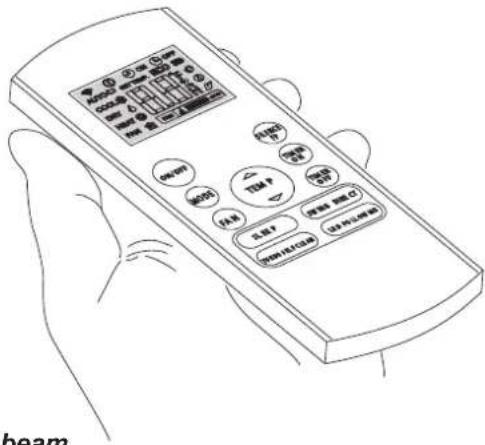
text_image
beam
• The remote control operates by means of an infrared beam.
- During use, there must not be any obstacle between the remote control and the air-conditioner.
- If other appliances in the room have remote controls (TV, stereo, etc...), there may be interference.
- Electronic and fluorescent lights may also interfere with transmissions between remote control and air-conditioner.
- Remove the batteries in case of prolonged disuse of the remote control.
3.1.1 - Insertion of batteries
The remote control is not supplied with batteries.
To insert the batteries correctly (figure 31):
a. Remove the batteries compartment cover.
b. Insert the batteries into the relevant compartment.

Check the polarity indicated on the bottom of the compartment.
c. Close the compartment correctly.
3.1.2 - Replacement of batteries
The batteries should be replaced when the display on the remote control does not appear sharply or when the remote control does not change the settings.

Always use new batteries and replace both at the same time.
The use of old or different batteries could generate malfunctioning of the remote control.
The remote control uses two dry alkaline 1.5V batteries (AAA.LR03/LR03X2).
When the batteries have been replaced, adjust the remote control clock.

When replacing batteries, replace both and dispose of the dead batteries in the appropriate collection centres and as required by law.
- If the remote control is not used for several weeks or longer, remove the batteries.
Any leaks from the batteries could damage the remote control. - The average life-span of the batteries, with normal use, is approx. six months. Replace the batteries when the indoor unit command receipt "beep" can no longer be heard, or if the transmission indicator on the remote control does not switch on.
EN - 25

Do not re-charge or disassemble the batteries. Do not throw the batteries into the fire. They can burn and explode.

If the battery liquid falls onto the skin or clothes, wash well with clean water. Do not use the remote control with batteries that have leaked.
The chemical products contained in the batteries can cause burns or other risks to health.
3.1.3 - Location of the remote controller
- Keep the remote control in a position from which the signal can reach the indoor unit receiver (max. distance approx. 8 metres - with the batteries charged) (figure 32).
The presence of obstacles (furniture, curtains, walls, etc.) between the remote control and indoor unit, reduces the capacity of the remote control.
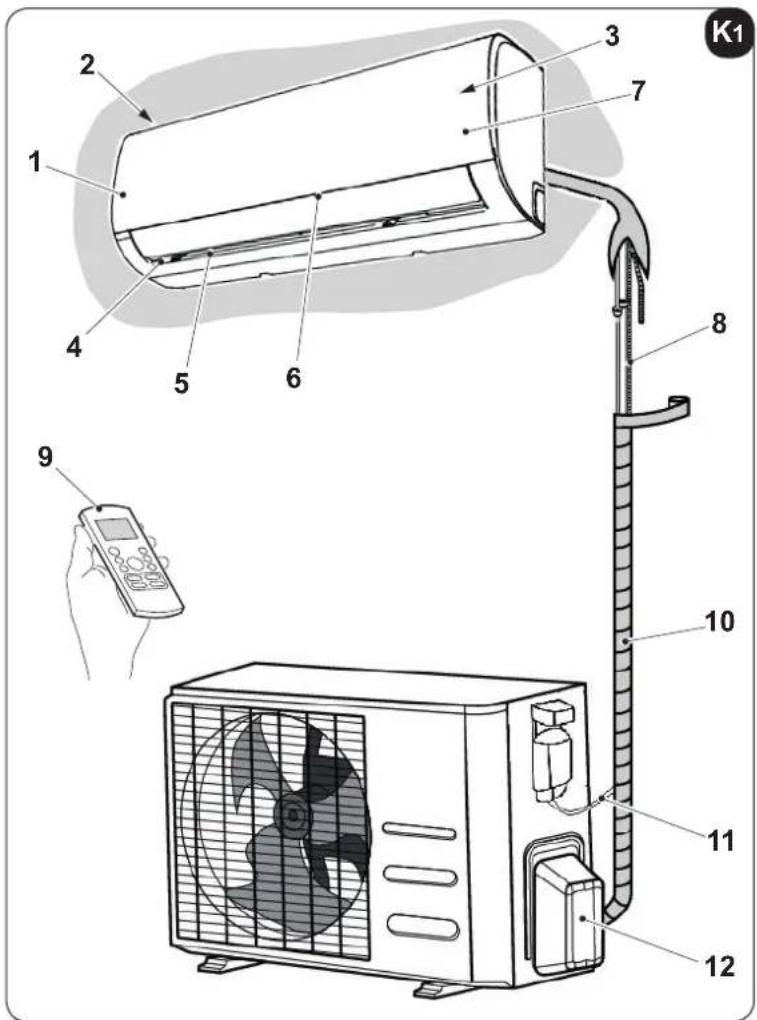
3.2 - COMPONENTS OF THE SYSTEM
(fig. "K1")
Indoor unit
1 Front panel
2 Air inlet
3 Air filter (under the panel)
4 Air outlet
5 Horizontal air flow grille
6 Vertical air flow louver(inside)
7 Display panel
8 Connecting pipe, drain hose
9 Remote control
Outdoor unit
10 Connective cable
11 Connecting pipe
12 Stop valve
text_image
Diagram of a wall-mounted air conditioner unit with numbered parts and a control panel, including a remote control.
All the pictures in this manual are for explanation purpose only.
They may be slightly different from the air conditioner you purchased (depend on model).
EN - 26

OLIMPIA
SPLENDID
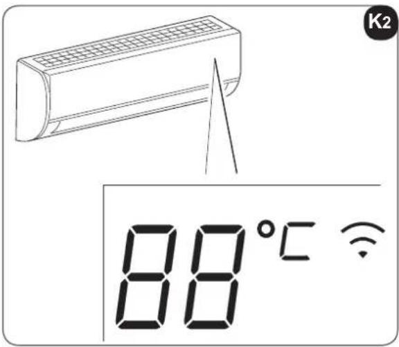
3.3 - FUNCTION INDICATOR ON INDOOR UNIT DISPLAY PANEL
(fig. K2)
The display panel shows the current setting temperature and function code enable/disable when the air conditioner is in operation.
In "Fan" and "Dehumidification" mode, the room temperature is displayed.
In the case of a fault, displays the error code.
3.3.1 - Function Codes
ON Light for 3 seconds when:
- TIMER ON is set
- SWING, TURBO or SILENCE features are enabled
OF Light for 3 seconds when:
- TIMER OFF is set
- SWING, TURBO, or SILENCE features are disabled
cF Lights up when the function that controls hot air in Heating mode is automatically activated.
df Lights up when the air conditioner starts defrosting automatically.
5C Lights up when SEL CLEAN function is enabled
FP Lights up when FROST PROTECTION function is enabled
Lights up when WIRELESS function is enabled
3.4 - DESCRIPTION OF REMOTE CONTROL (fig. 33)
The remote control is the interface between the air-conditioner and the customer, so it is very important to learn all its functions, the use of the various controls and the meaning of the symbols marked on it.
3.4.1 - Indicators on remote controller (fig. 33)
A. Transmission
This transmission indicator lights when remote controller transmits signals to the indoor unit.
B. Operating mode
Displays the operating mode active.
It includes: AUTO ⬇, COOL ✕, DRY ⚠, HEAT ✘, FAN ONLY ⏱ and return to AUTO ⬇
C. Follow me Function
D. Temperature
Displays the required temperature (from 17°C to 30°C).
When you set the operating mode to FAN ONLY, no temperature setting is displayed.
text_image
K2 88°CE. Timer
Indicate Timer on/off time (0÷23:50 hours).
F. Fan speed
Displays the fan speed set, AUTO and three speed levels can be indicated
“”(LOW) - “”(MED) - “”(HIGH)
"AUTO" is displayed when the operational mode is "AUTO" or "DRY".
G. Sleep
Displayed under sleeping operation.
Press the SLEEP button again to remove.

The remote control display is illustrated just for greater clarity.
3.4.2 - Description of the remote control keys (figure 34)
1. MODE SELECTION key
Every time this key is pressed, a mode is selected in sequence,
AUTO > COOL DRY > HEAT > FAN and then back to AUTO.
2. ON/OFF key
Press this key to start the appliance and press it again to stop the appliance.
3. SWING key
Press this key to start the louvres and press it again to stop them.
4. TEMP/TIME key
Press the key to increase the indoor temperature set or to adjust the TIMER in a clockwise direction.
Press the ▼key to lower the indoor temperature set or to adjust the TIMER in an anti-clockwise direction.
5. FAN key
Used to select fan speed, it has four levels AUTO, LOW, MED or HIGH.
The fan speed changes every time this key is pressed.
6. TURBO/SELF CLEAN key
Press this key for less than 2 seconds to start the TURBO function.
If the key is held down for more than 2 seconds, the SELF CLEAN function is activated.
3.4.3 - Follow Me function
The remote control acts as a remote thermostat, allowing correct control of the temperature in its position.
- To activate the Follow Me function, point the remote control towards the unit and press the “Follow Me” button.
The remote control displays the real temperature in its own position and sends this signal to the air conditioner every 3 minutes, until the button is pressed again.
If the unit does not receive the Follow Me signal for 7 minutes, it emits a “beep”, which signals that the Follow Me mode has ended.

The Follow Me function is not available in the DRY and FAN mode.
- If the operating mode is pressed, or the unit is switched off, the Follow Me function is annulled automatically.
EN - 28
3.4.4 - TURBO function
- In TURBO mode, the fan motor functions at a very high speed in a way to reach the temperature set in the least time possible.
3.4.5 - SELF CLEAN function
- In SELF CLEAN mode, the air conditioner automatically cleans and dries the evaporator and keeps it fresh for successive use.
The function is used on switch off of cooling mode to clean the evaporator and keep it fresh for successive use.
This function is easy to activate and accessible from the remote control.
- The air conditioner will operate as follows:
- Fan only mode with fan at low speed (13 minutes) -
- Heating with fan at low speed (1 minute)
- Fan only operation (2 minutes)
- Stop operation
- Unit switch-off.

This function is only available in COOL (AUTO COOL, FORCED COOL) and DRY modes.
Before selecting this function, it is recommended to start the air conditioner in cooling mode for approx. 30 minutes.
Once the Auto Clean function is activated, all timer settings will be annulled.
If the AUTO CLEAN button is pressed again during operation in auto-clean mode, the function stops and the appliance switches off.
3.4.6 - SILENCE function
• This function reduces noise.
3.4.7 - FP function
- The FROST PROTECTION function sets the temperature at 8^ .
The function is available in "HEAT" mode only.
3.4.8 - TIMER keys (7 and 8)
- These keys are used to set the switch-on "ON" and switch-off "OFF" time of the air conditioner.
3.4.9 - SILENCE/FP key (9)
- Press this key for less than 2 seconds to start the SILENCE function.
If the key is held down for more than 2 seconds, the FP (FROST PROTECTION). function is activated.
EN - 29
3.4.10 - SLEEP key (10)
- Press this key to access the SLEEP mode; press it again to annul.
The function can be activated only in COOL, HEAT and AUTO modes and allows to maintain the temperature as comfortable as possible.

When the unit is running in SLEEP mode, this will be annulled if the MODE, FAN SPEED and ON/OFF keys are pressed.
3.4.11 - LED/FOLLOW ME key (11)
- Press this key for less than 2 seconds to start the LED function.
If the key is held down for more than 2 seconds, the FOLLOW ME function is activated. - Press the LED key to reset the air conditioner digital display; press it again to activate it.
3.4.12 - Automatic operation (figure 34)
When the air conditioner is put in "AUTO" mode, these will automatically select cooling, heating or fan, depending on the temperature that has been selected and the room temperature.
Once the operational mode has been selected, the functioning conditions are stored in the memory of the unit microcomputer and the air conditioner starts to function in the same conditions, when simply pressing the "ON/OFF" key of the remote control.
START
Check that the unit is connected and is powered electrically.
a. Press the "MODE" key (1) to select "AUTO" mode.
b. Set the desired temperature by pressing the "TEMP" keys (4).
Normally the temperature is between 21^ C and 28^ C.
c. When the remote control is "OFF", press the "ON/OFF" key (2) to start the air conditioner.
STOP
a. Press the "ON/OFF" key (2) to stop the air conditioner.
If the AUTO mode is not wanted, the desired conditions can be selected manually.
When AUTO mode is selected, the fan speed does not have to be set; the fan speed is controlled automatically.
3.4.13 - Functioning in Cooling/Heating/Fan only mode (figure 34)
START
Check that the unit is connected and is powered electrically.
a. Press the "MODE" key (1) to select the "COOL", "HEAT", or "FAN ONLY". mode.
b. Set the desired temperature by pressing the "TEMP" keys (4).
Normally the temperature is between 21^ C and 28^ C.
c. When the remote control is "OFF", press the "ON/OFF" key (2) to start the air conditioner.
d. Press the fan speed key (FAN "5") to select "AUTO", "LOW", "MED", or "HIGH".
e. When the remote control is "OFF", press the "ON/OFF" key (2) to start the air conditioner.
The FAN ONLY mode does not adjust the temperature, therefore, to select this mode, only perform the "a", "c", "d", "e" phases.
STOP
a. Press the "ON/OFF" key (2) to stop the air conditioner.
If the AUTO mode is not wanted, the desired conditions can be selected manually.
3.5 - ADJUSTING AIR FLOW DIRECTION
Adjust the direction of the air correctly in order to prevent the flow of air from being annoying (figure 3) or generating irregular temperatures in the room.
a. Adjust the horizontal louvres using the remote control.
b. Adjust the vertical louvres manually (figure 35).

Before adjusting the vertical louvres, disconnect the electric power supply.
3.5.1 - Adjustment of the vertical direction of the air (high - low) (figure "36")
The air conditioner automatically adjusts the vertical direction of the air, according to the operational mode. Perform this function when the unit is operating.
Hold the “SWING” key down on the remote control (figure “34” - ref. 3) to move the louvres in the desired direction.

- The AIR DIRECTION and SWING buttons will be disabled when the air conditioner is not operating (also when the TIMER ON is set).
- Do not activate the air conditioner for long periods with the air downwards in cooling or dehumidification modes.
Otherwise, humidity may form on the surface of the horizontal louvres, which could fall onto the floor or furnishings.
- Do not move the horizontal louvres manually.
Always use the AIR DIRECTION or SWING button. If directed manually, malfunctioning may occur. If louvre malfunctioning occurs, stop the conditioner and re-start it.
- When the conditioner is switched on immediately after it has been switched off, the horizontal louvres may not move for approx. 10 seconds.
- The angle of opening of the horizontal louvres must not be too small, since performance in COOLING or HEATING mode may not be perfect for the flow of air that is too narrow.
- Never activate the unit with the horizontal louvres in closed position.
- When the conditioner is connected to the power supply (initial power supply), the horizontal louvres may make a noise for 10 seconds. It is normal operation.
EN - 31
3.6- DEHUMIDIFICATION (figure 34)
START
Check that the unit is connected and is powered electrically.
a. Press the "MODE" key (1) to select "DRY" mode.
b. Set the desired temperature by pressing the "TEMP" keys (4).
c. When the remote control is "OFF", press the "ON/OFF" key (2) to start the air conditioner.
STOP
a. Press the "ON/OFF" key (2) to stop the air conditioner.

Fan speed cannot be adjusted when the unit is in AUTO and DRY modes.
Check that the unit is connected and is powered electrically.
a. Press one of the TIMER keys (7 and 8) as desired.
The current adjustment of the timer is shown on the display at the side of the Timer ON and Timer OFF indicators and will flash.
b. Press the "TEMP" keys (4) to select the desired time.
Forward
Backward
Every time one of the “TEMP” keys (4) is pressed, the time moves forward or backward by 30 minutes, depending on the direction of pressing.
c. Once the time has been set for TIMER ON and TIMER OFF, check that the TIMER indicator on the indoor unit display is on.
MODIFICATIONS
- Repeat phases "a", "b" and "c" to change the settings.
3.7.1 - Switch-on timer setting from the remote control (figures 33, 34 and 37)
When the unit has been switched on, select the operational mode, the desired temperature and fan speed with which the unit will activate on scheduled switch-on.
Successively put the machine in Stand-By.
Press the “TIMER ON” key (7) to set the desired delay (from 1 to 24 hours), after which the unit will switch on (starting from confirmation of the timer).
If no key is pressed within 5 seconds, the timer setting function ends automatically.
The remote control displays the countdown until switch-on.
Once the time set has expired, the unit starts with the last settings selected.
3.7.2 - Switch-off timer setting from the remote control (figures 33, 34 and 38)
With the unit in any operational mode, press the "TIMER OFF" key (8) to set the desired delay (from 1 to 24 hours), after which the unit will switch off (starting from confirmation of the timer).
If no key is pressed within 5 seconds, the timer setting function ends automatically.
The remote control displays the countdown until switch-off.
Once the time set has passed, the unit switches off.
3.7.3 - Setting combined timer
(Simultaneous setting of the ON and OFF timers)
TIMER OFF > TIMER ON (figures 33, 34 and 39)
(On => Stop => Start functioning)
This function is useful if the air conditioner is to be switched off after going to bed and switched back on in the morning or when returning home.
Example:
The time is 20:00. If the air conditioner is to be switched off at 23:00 and switched back on at 06:00.
a. Press the "TIMER OFF" key (8) to display "TIMER OFF". the time flashes.
b. Press the "TEMP" keys (4) until the value "3:00" is set near to the "TIMER OFF" indicator.
c. Press the "TIMER ON" key (7) to display "TIMER ON". the time flashes.
d. Press the "TEMP" keys (4) until the value "10:00" is set near to the "TIMER ON" indicator.
e. Wait 3 seconds, the time set will stop flashing and the function will be active.
TIMER ON > TIMER OFF (figures "33", "34" and "40")
(On => Stop => Start functioning)
This function is useful if the air conditioner is to be switched on before getting up and switched off after leaving home.
Example:
The time is 20:00. If the air conditioner is to be switched on at 06:00 the next morning and switched of at 08:00.
a. Press the "TIMER ON" key (7) to display "TIMER ON". the time flashes.
b. Press the "TEMP" keys (4) until the value "10:00" is set near to the "TIMER ON" indicator.
c. Press the "TIMER OFF" key (8) to display "TIMER OFF". the time flashes.
d. Press the "TEMP" keys (4) until the value "12:00" is set near to the "TIMER OFF" indicator.
e. Wait 3 seconds, the time set will stop flashing and the function will be active.
3.8 - MANUAL OPERATION (figures 41 and 42)
Manual operation can be used temporarily if the remote control cannot be found or its batteries are discharged.
a. Open and lift the front panel to an angle in which it blocks and a "click" is heard (figure 41).
b. Press the control key once (AUTO/COOL) to start operation in "AUTO" mode (figure 42).
c. Close the panel well, taking it back to its original position (figure 46).
- By pressing the manual key, the operating passes in sequence to:
AUTO > COOL > OFF.
- Press the key twice to start the unit in forced "COOL" mode.
This mode must be used for the inspection only.
- By pressing the key a third time. operation stops and the air conditioner switches off.
- To restore remote control operation, use the remote control directly.
4 - MAINTENANCE AND CLEANING

Before proceeding with any maintenance and cleaning, always make sure the system has been switched off, using the remote control, and the power supply plug has been disconnected from the system socket (or the upstream master isolating switch is positioned at "0" OFF).

Do not touch the metal parts of the unit when removing the air filters. are very sharp. Cuts or injury risk.
4.1 - CLEANING
4.1.1 - Cleaning the indoor unit and remote controller
Use a dry cloth to clean the indoor unit and the remote control.
A cloth dampened in cold water can be used to clean the indoor unit if it is very dirty.
The front panel can be removed and cleaned with water. Dry using a dry cloth.

Do not use a chemically-treated or anti-static cloth to clean the unit. of use gasoline, solvent, polish or similar solvents.
These products could cause the breakage or deformation of the plastic surface.
EN - 34
4.1.2 - Cleaning the air filter (fig. "41", "43", "44" e "45")
A clogged air filter reduces the cooling efficiency of this unit. Please clean the filter once every 2 weeks.
a. Lift the indoor unit panel up to an angle until it stops with a clicking sound (fig."41").
b. Take hold of the handle of the air filter and lift it up slightly to take it out from the filter holder (fig. "43a"), then pull it downwards (figura "43b").
c. Remove the air filter.
d. Clean the air filter using a suction device or wash it with water and then dry it in a cool place.
e. Remove the electrostatic filter (if provided to accompany) and the active carbon filter (if provided to accompany) from the air filter as shown in figure "44".

Do not touch this Electrostatic Filter within 10 minutes after opening the inlet grille, it may cause an electric shock.
f. Clean the Electrostatic Filter with mild detergent or water and dry in the sunlight for two hours.
g. Insert the electrostatic filter again (if supplied) + the active charcoal filter (if supplied).
h. Insert the upper part of the air filter into the unit, paying attention that the left and right edges are correctly aligned and then re-position the filter in the relevant seat (figure "45").
i. Close the panel well, taking it back to its original position (figure "46").
4.2 - MAINTENANCE
If you plan to idle the unit for a long time, perform the following:
a. Activate the fan for approx. half a day to dry the inside of the unit.
b. Stop the air conditioner and disconnect the power supply.
c. Remove the batteries from the remote control.

The outdoor unit requires maintenance interventions and periodic cleaning. OT PERFORM THEM ALONE.
Contact the dealer or after-sales assistance service.
Checks before resuming use of the air conditioner:
a. Check that the wires are not broken or disconnected.
b. Check that the air filter is clean and installed correctly.
Clean the filters after a long period of inactivity of the air conditioner.
c. Check that the air outlet or inlet are not obstructed (especially after a long period of inactivity of the air conditioner).

Do not touch the metal parts of the unit when removing the filter. He is a risk of injury due to the sharp metal edges.

Do not use water to clean the internal parts of the air conditioner. bourse to water can ruin the isolation, with the risk of electric shocks.

When cleaning the unit, make sure the switch is off and the power supply is disconnected.
EN - 35
4.2.1 - RECOMMENDATIONS FOR ENERGY SAVINGS
Below find simple recommendations for reducing consumption:
• Always and constantly keep the filters clean (see maintenance and cleaning chapter).
- Keep the doors and windows of the rooms to be climate controlled closed.
- Avoid the sun's rays penetrating freely into the room (we recommend using curtains or lowering blinds or closing the shutters).
- Do not obstruct the unit air flow (inlet and outlet), i.e. in addition to bad performance of the system, it also affects correct operation and the possibility of irreparable faults to the units.
4.3 - FUNCTIONAL ASPECTS NOT TO BE MISTAKEN FOR ANOMALIES
The following events may occur during normal operation:
1. PROTECTION OF THE AIR CONDITIONER
a. The compressor will not re-start for 3 minutes after it has been switched off.
- The unit is designed not to blow cold air in HEATING mode, when the internal heat exchanger is in one of the following conditions and the temperature set has not been reached.
- When heating has just been started.
- Defrosting.
- Low temperature heating.
b. The indoor or outdoor fans stop running during defrosting.
- Frost may form on the outdoor unit during the heating cycle, when the outdoor temperature is low and humidity is high, which may cause lower heating efficiency or air conditioning.
- If this occurs, the air conditioner will stop heating mode and will automatically activate the defrosting function.
- The time required to perform defrosting can vary from 4 to 10 minutes, depending on the outdoor temperature and the amount of frost that has formed on the outdoor unit.
2. WHITE MIST ESCAPES FROM THE INDOOR UNIT
- White mist may be generated due to the large temperature difference between the inlet air and the outlet air in COOLING mode in indoor environments with high relative humidity.
- The white mist may be generated by the humidity produced by the defrosting process when the air conditioner re-starts in COOLING mode after defrosting.
3. SLIGHT AIR CONDITIONER NOISE
- A low hissing noise may be heard when the compressor is running, or has just been switched off. It is the noise of the refrigerant running or stopping.
- A low "squeaking" noise may also be heard when the compressor is running, or has just been switched off. This is caused by expansion due to the heat or contraction due to cold of the plastic parts of the unit, when the temperature changes.
- A noise may be heard due to the louvre restoring itself to its original position on commissioning.
4. DUST IS BLOWN OUT FROM THE INDOOR UNIT
- This is normal when the air conditioner is re-started after a long period of inactivity, or is used for the first time.
5. A STRANGE ODOUR IS DETECTED COMING FROM THE INDOOR UNIT
- It is caused by the indoor unit, which releases the odours absorbed by the construction materials, the furnishings or from smoking.
6. THE AIR CONDITIONER GOES TO FAN ONLY MODE FROM HEATING AND COOLING MODE
- When the indoor temperature reaches the temperature set on the air conditioner, the compressor stops automatically and the air conditioner goes to fan only mode. The compressor will start again, when the indoor temperature increases in cooling mode, or lowers in heating mode.
7. POSSIBLE DRIPPING OF WATER
- Droplets of water may form on the surface of the indoor unit when cooling is activated in high relative humidity conditions (relative humidity above 80%).
Adjust the horizontal louvre to maximum opening to allow the air to escape and select high fan speed.
8. HEATING MODE
- The air conditioner takes heat from the outdoor unit and releases it through the indoor unit during operation in heating mode. When the outdoor temperature lowers, the heat introduced by the air conditioner consequently decreases.
- Simultaneously, the air conditioner heat production load increases due to the greater difference between the indoor and outdoor temperatures.
- If a comfortable temperature cannot be obtained only with the air conditioner, it is recommended to use an additional heating device.
9. AUTOMATIC RE-START FUNCTION
- The indoor unit has an automatic re-start button (auto-reset). Whenever there is unexpected power failure, the settings present at the time of the voltage drop will be restored. The unit will automatically re-activate the previous operational settings after 3 minutes from the voltage being restored.
10. LIGHTENING OR ELECTRIC EQUIPMENT
- Lightening or wireless phones working in the vicinity could cause the air conditioner to malfunction.
EN - 37
4.4 - TROUBLESHOOTING
1. The unit may stop running or keep running safely if:
- the LEDs keep flashing
- on the display appears one of the following codes:
E(x), P(x), F(x), EH(xx), EL(xx), EC(xx), PH(xx), PL(xx), PC(xx)
Wait approximately 10 minutes; the problem may solve by itself.
If not, disconnect power supply and reconnect it. Switch on the unit.
If the problem persists, disconnect the unit from the power supply and contact the closest service centre.
2. Stop the air conditioner immediately is one of the following anomalies occurs.
Disconnect the electric power supply and contact the nearest after-sales assistance service.
Problem:
- The fuses blow frequently or the automatic switch intervenes often.
- Water or other objects have entered the air conditioner.
- The remote control does not function or functions anomalously.
4.4.1 - Malfunctioning

Do not try to repair the unit alone.
| Malfunctioning Cause What must be done? | ||
| The unit will not start. Current failure | Wait for the current to be restored. | |
| The unit is disconnected from the current. | Check that the plug is inserted in the wall socket. | |
| A fuse has blown. Replace the fuse. | ||
| The remote control batteries may be discharged. | Replace the batteries. | |
| The time set with the timer may not be correct. | Wait or annul the timer setting. | |
| The unit does not cool or heat the room well (only for cooling/heating models), while air escapes from the conditioner. | Incorrect temperature setting. Set the temperature correctly. Consul the "Using the remote control" chapter for the procedure. | |
| The air filter is clogged. Clean the air filter. | ||
| The doors or windows are open. Close the doors or windows. | ||
| The air inlet or outlet vents of the indoor or outdoor units are blocked. | First, remove the obstructions and then re-start the unit. | |
| The compressor 3 minute protection has activated. | Wait. | |
| If the problem has not been solved, contact the local dealer or nearest after-sales assistance service.Provide detailed information regarding malfunctioning and the unit model. | ||
EN - 38
5 - GENERAL TROUBLESHOOTING
5.1 - ERROR DISPLAY (INDOOR UNIT)
When indoor unit a recognized error, the indicator light will flash in a corresponding series, the timer display may turn on or begin flashing, and an error code will be displayed. These error codes are described in the following table:
| Display Error information | |
| E0 Indoor unit | EEPROM parameter error |
| E1 Indoor / outdoor units communication error | |
| E3 The indoor fan speed is operating outside of the normal range | |
| E4 Indoor room temperature sensor T1 is in open circuit or has short circuited | |
| E5 Evaporator coil temperature sensor T2 is in open circuit or has short circuited | |
| EC Refrigerant leak detected | |
| F0 Overload current protection | |
| F1 Outdoor ambient temperature sensor T4 open circuit or short circuit | |
| F2 Condenser coil temperature sensor T3 is in open circuit or has short circuited | |
| F3 Compressor discharge temperature sensor TP open circuit or short circuit | |
| F4 Outdoor unit EEPROM parameter error | |
| F5 The outdoor fan speed is operating outside of the normal range | |
| P0 IPM malfunction or IGBT over-strong current protection | |
| P1 Over voltage or over low voltage protection | |
| P2 High temperature protection of IPM module | |
| P4 Inverter compressor drive error | |
FOR EACH ERROR:
Switch off the unit and wait 2 minutes before restarting it, if the problem persists, please contact the assistance centre.
EN - 39
5.2 - OTHER ERROR
The display board may show a garbled code or a code undefined by the service manual. Ensure that this code is not a temperature reading.
Test the unit using the remote control.
- If the unit does not respond to the remote, the indoor PCB requires replacement.
- If the unit responds, the display board requires replacement.
6 - TECHNICAL DATA

For the technical data listed below, consult the characteristic data plate affixed to the product.
• Power supply voltage
• Maximum power absorbed
• Maximum current absorbed
- Cooling capacity
- Refrigerant gas
• Protection rating of the casings
• Max. operating pressure
| Model MONO | |
| Outdoor unitsDimensions (mm)(Width x Height x Depth)...... | 800 x 554 x 333 |
| Outdoor unitsWeight (kg) without packaging)...... | 34,7 Kg |
| Operating limit conditions | |
| • Maximum operating temperatures in cooling mode | internal DB 32°Cexternal DB 43°C |
| • Minimum operating temperatures in cooling mode | internal DB 17°Cexternal DB -15°C |
| • Maximum operating temperatures in heating mode | internal DB 30°Cexternal DB 30°C |
| • Minimum operating temperatures in heating mode | internal DB 0°Cexternal DB -22°C |
| • Wiring diagram figure 48 |
EN - 40
TABLE DES MATIÈRES GÉNÉRALE
0 - MISES EN GARDE....3
0.1 - INFORMATIONS GÉNÉRALES 3
0.2 - SYMBOLOGIE 3
0.2.1 - Pictogrammes rédactionnels....3
0.3 - MISES EN GARDE GÉNÉRALES ....5
0.4 - À PROPOS DES GAZ FLUORÉS....8
0.5 - UTILISATION PRÉVUE....8
0.6 - ZONES À RISQUE....8
1 -DESCRIPTION DE L'APPAREIL 9
1.1 - LISTE DES COMPOSANTS FOURNIS 9
1.2 - MATÉRIEL NÉCESSAIRE EXCLU DE LA LIVRAISON 9
1.3 - STOCKAGE 10
1.4 - RÉCEPTION ET DÉBALLAGE 10
6 - DONNÉES TECHNIQUES....40
IMINATION
text_image
401mm 229mm 228mm 126mm 42mm Ø 65mm Ø 65mm 47mm 58mmFR - 15
2.5.3 - Raccordement de la tuyauterie (figure 7)
text_image
340mm IN IN OUT 514mm
text_image
A = ① kg B = ② kg A + B = ③ kg
text_image
Line drawing of a remote control device with labeled buttons and display screen
text_image
Diagram of a household air conditioner unit with numbered parts and a hand holding a remote control.
text_image
340mm IN IN OUT 514mmX4
text_image
A = ① kg B = ② kg A + B = ③ kg
text_image
Diagram showing a building with labeled components A and B, including directional arrows and a circular symbol inside the structure.
text_image
Line drawing of a remote control device with labeled buttons and display screen
text_image
Diagram of a wall-mounted air conditioner unit with numbered parts and a hand holding a remote control.
1. SCHUTZ DES KLIMAGERÄTS
E(x), P(x), F(x), EH(xx), EL(xx), EC(xx), PH(xx), PL(xx), PC(xx)
text_image
A 1 2 3 4 5 6 7 8 9 10 ALYAS PRO E INVERTER 9 INVERTER 12 O L I M P I A O L I M P I A O L I M P I A O L I M P I A O L I M P I A O L I M P I A O L I M P I A O L I M P I A O L I M P I A O L I M P I A O L I M P I A O L I M P I A O L I M P I A O LI N T R U S T O L I M P I A O L I M P I A O L I M P I A O L I M P I A O L I M P I A O L I M P I A O L I M P I A O L I M P I A O L I M P I A O L I M P I A O L I M P I A O L I M P I A O L i m p i n t a l e1.2 - MATERIAL NO SUMINISTRADO DE SERIE
text_image
401mm 229mm 126mm 42mm 228mm Ø 65mm Ø 65mm 47mm 58mmES - 15
text_image
340mm IN IN OUT 514mm
text_image
A = ① kg B = ② kg A + B = ③ kg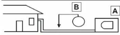
text_image
Diagram showing a house connected to a pump system with labeled components A and B
text_image
Line drawing of a remote control device with labeled buttons and display screen
text_image
Technical diagram of a wall-mounted air conditioner unit with numbered components and a hand holding a remote control.
E(x), P(x), F(x), EH(xx), EL(xx), EC(xx), PH(xx), PL(xx), PC(xx)
text_image
401mm 229mm 228mm 126mm 42mm Ø 65mm Ø 65mm 47mm 58mmPT - 15
text_image
340mm IN IN OUT 514mm
text_image
A = ① kg B = ② kg A + B = ③ kg
text_image
Diagram showing a house connected to a pump system with labeled components A and B
0 - WAARSCHUWINGEN....3
0.1 - ALGEMENE INFORMATIE 3
0.2 - SYMBOLLEN 3
0.2.1 - Redactionele pictogrammen....3
0.3 - ALGEMEEN ADVIES 5
0.4 - OPMERKINGEN OVER DE GEFLUOREERDE GASSEN 8
0.5 - BEOOGD GEBRUIK 8
0.6 - RISICOZONES....8
1 -OMSCHRIJVING VAN HET APPARAAT 9
1.1 - LIJST VAN DE MEEGELEVERDE ONDERDELEN 9
1.2 - NIET MEEGELEVERD VEREIST MATERIAAL 9
1.3 - OPSLAG....10
1.4 - ONTVANGST EN UITPAKKEN 10
INFORMATIE VOORBEHOUDEN VOOR DE "INSTALLATIETECHNICUS"
2 - INSTALLATIE 10
2.1 - INSTALLATIEWIJZEN....10
2.1.1 - Minimaal oppervlak van de ruimte in het geval van 11
2.2 - UIT TE VOEREN CONTROLES VOOR DE INSTALLATIE....11
2.3 - GEGEVENSTABEL 13
2.4 - KEUZE VAN DE POSITIE VAN DE BINNENUNIT....14
2.5 - MONTAGE VAN DE BINNENUNIT 15
3.8 - MANUELE WERKING....34
4 - ONDERHOUD EN REINIGING 34
4.1 - REINIGING....34
1 - OMSCHRIJVING VAN HET APPARAAT
1.1 - LIJST VAN DE MEEGELEVERDE ONDERDELEN
natural_image
Technical line drawing of a rectangular industrial air conditioning unit with fan grille and mounting base (no text or symbols)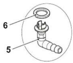
text_image
6 5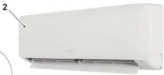
natural_image
White air conditioner unit with label pointing to part 2 (no text or symbols on body)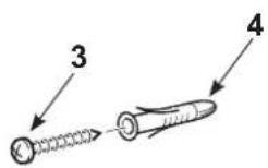
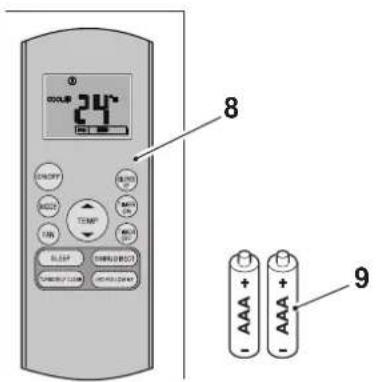
text_image
24°C 8 9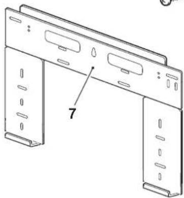
natural_image
Technical line drawing of a mechanical bracket with mounting holes and a numbered label (7), no readable text or symbols present.10
text_image
ALYAS PRO E INVERTER 9 INVERTER 121.2 - NIET MEEGELEVERD VEREIST MATERIAAL
KEER DE VERPAKKING NIET OM.
1.4 - ONTVANGST EN UITPAKKEN
text_image
401mm 229mm 228mm 126mm 42mm Ø 65mm Ø 65mm 47mm 58mmNL - 15
text_image
340mm IN IN OUT 514mm
2.6.2 - Montage buitenunit
text_image
A = ① kg B = ② kg A + B = ③ kg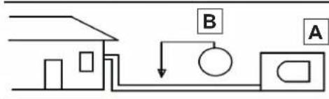
flowchart
graph TD
    A["House"] --> B["Control Box"]
    B --> C["Arrow B"]
    C --> D["Arrow A"]

text_image
Line drawing of a remote control device with labeled buttons and display screen
text_image
Diagram of a household air conditioner unit with numbered parts and a hand holding a remote control.
(On => Stop => Start werking)
(On => Stop => Start werking)
E(x), P(x), F(x), EH(xx), EL(xx), EC(xx), PH(xx), PL(xx), PC(xx)