
Unico Pro EVAN - Air Conditioning OLIMPIA SPLENDID - Free user manual and instructions
Find the device manual for free Unico Pro EVAN OLIMPIA SPLENDID in PDF.

| Product type | Reversible wall air conditioning (heat pump) |
| Brand | Olimpia Splendid |
| Model | Unico Pro EVAN |
| Refrigerant | R32 (GWP = 675) |
| Power supply | 230 V ~ 50 Hz, single phase |
| Operating modes | Cooling, heating, dehumidification, ventilation, automatic |
| Special functions | ECO, SILENT, programmable timer (2 programs), deflector oscillation |
| Connectivity | Wi-Fi (OS Home app), MODBUS RTU RS485, input for wired controller B1012 |
| Remote control | Infrared, range ~8 m, AAA batteries (not included) |
| Filters | Standard air filter, purifying filter (green), activated carbon filter (black) |
| Filter cleaning | Every 2 weeks or upon light indication |
| Installation | Wall (high or low), ceiling or floor possible via electronic configuration |
| Wall hole diameter | 162 mm or 202 mm |
| Condensate drainage | By gravity (min. slope 3%) or built-in pump for heat pump models |
| Safety | Gas leak protection, stop on alarm (error code), keypad lock |
| Operating temperatures (cooling) | Indoor: 18-35 °C DB / Outdoor: -10 to 43 °C DB |
| Operating temperatures (heating) | Indoor: 16-27 °C DB / Outdoor: -15 to 24 °C DB |
| Included accessories | External grilles, flanges, condensate hose, green and black filter, mounting kit |
Frequently Asked Questions - Unico Pro EVAN OLIMPIA SPLENDID
User questions about Unico Pro EVAN OLIMPIA SPLENDID
0 question about this device. Answer the ones you know or ask your own.
Ask a new question about this device
Download the instructions for your Air Conditioning in PDF format for free! Find your manual Unico Pro EVAN - OLIMPIA SPLENDID and take your electronic device back in hand. On this page are published all the documents necessary for the use of your device. Unico Pro EVAN by OLIMPIA SPLENDID.
USER MANUAL Unico Pro EVAN OLIMPIA SPLENDID
natural_image
Technical line drawing of a rectangular air conditioner unit (no text or symbols)UNICO PRO R32
EVAN
Caution: risk of fire
2.5 - ALLACCIAMENTO ELETTRICO....25
2.6 - CONFIGURAZIONI TRAMITE PANNELLO DI CONTROLLO....27
4.2 - ACCESSORI B1014 - B1012 42
4.3 - MODBUS RTU RS485 42
4.3.1 - Connessione MODBUS RTU RS485 42
5 - PULIZIA E MANUTENZIONE....43
5.1 - PULIZIA 43

IT - 18
natural_image
Illustration of two hands holding a cylindrical object with a circular component, labeled 'H' (no text or symbols on the objects themselves)natural_image
Illustration of two hands stretching a cylindrical object on a brick wall (no text or symbols)natural_image
Illustration of a hand using a mechanical device to interact with chains (no text or symbols visible)
natural_image
Mechanical assembly diagram showing a component being inserted into a housing with a tool, no text or symbols presentIT - 23

natural_image
Diagram of a mechanical component with a triangular cutout and a shaded section, no text or symbols present2.5 - ALLACCIAMENTO ELETTRICO
natural_image
Illustration of a hand using a power plug to install an electrical socket (no text or symbols present)


4.2 - ACCESSORI B1014 - B1012
natural_image
Illustration of a hand using a power plug to switch an electrical outlet (no text or symbols present)
natural_image
Illustration of two different air conditioner unit designs, showing hand positioning and cleaning process (no text or symbols)
natural_image
Illustration of a hand using a power plug to switch an electrical socket (no text or symbols present)1 - DESCRIPTION OF THE APPLIANCE....12
1.1 - LIST OF THE COMPONENTS SUPPLIED 12
1.2 - STORAGE....13
1.3 - RECEIPT AND UNPACKING....13
1.4 - APPLIANCE COMPONENTS DESCRIPTION 14
2 - INSTALLATION ....14
2.1 - INSTRUCTIONS FOR INSTALLATION....14
2.2 - SIZE AND SPECIFICATIONS OF THE ROOM IN WHICH TO INSTALL
THE AIR CONDITIONER ....14
2.3 - CHOOSING THE POSITION OF THE UNIT 15
2.4 - UNIT ASSEMBLY 17
2.4.1 - Drilling the wall 17
2.4.2 - Preparing the condensate discharge....19
2.4.3 - Assembly of the air ducts and external grids....20
2.4.4 - Preparing the holes on the machine....23
2.4.5 - Positioning of the device on the anchor bracket.....24
2.5 - ELECTRIC HOOK-UP 25
2.6 - CONFIGURATIONS THROUGH THE CONTROL PANEL....27
2.6.1 - Configuration of the electronics for low or high wall installation 27
2.6.2 - Energy boost/System enable configuration....27
2.6.3 - Input setting configuration 28
2.6.4 - Temperature unit of measurement configuration....28
2.6.5 - Heat pump / only cooling / only heating configuration....28
3 - USE....29
3.1 - WARNINGS....29
3.2 - DESCRIPTION OF THE WARNING PANEL 30
3.3 - USE OF THE REMOTE CONTROL....31
3.3.1 - Insertion of batteries....32
3.3.2 - Replacement of batteries....32
3.3.3 - Location of the remote controller 33
3.4 - DESCRIPTION OF REMOTE CONTROL 33
3.4.1 - Description of the remote control keys 33
3.4.2 - Description of the remote control display 34
3.5 - DESCRIPTION OF THE AIR CONDITIONER FUNCTIONS....34
3.5.1 - Main switch-on and running management....34
3.5.2 - ECO key 34
3.5.3 - Turning the unit ON/OFF 34
3.5.4 - Operation in "Cooling" mode only....35
3.5.5 - Operation in "Dehumidification" mode only 35
3.5.6 - Operation in "Ventilation" mode only 35
3.5.7 - Operation in "Spa" mode only (Automatic) 35
3.5.8 - Operation in "Heating" mode only (only models fitted with heating pump)....36
3.5.9 -Checking airflow direction....36
3.5.10 - Checking fan speed 36
3.5.11 - SILENT key 37
3.5.12 - Timer setting ....37
EN - 1
3.5.13 - Timer and clock setting 38
3.5.14 - Timer setting (PROGR. 1 and PROGR. 2) (T2)....38
3.5.15 - Timer activation and deactivation....39
3.5.16 - Reset of all the remote controller functions....39
3.5.17 - Managing the unit if the remote control is not available....40
3.6 - RECOMMENDATIONS FOR ENERGY SAVINGS....40
4 - FUNCTIONS AND ACCESSORIES ....40
4.1 - WIFI 40
4.1.1 - Appliance connection .... 40
4.1.2 - App installation 40
4.1.3 - Registration of the app ....41
4.1.4 - Use of the app .... 41
4.2 - ACCESSORIES B1014 - B1012....42
4.3 - MODBUS RTU RS485 42
4.3.1 - MODBUS RTU RS485 connection....42
5 - MAINTENANCE AND CLEANING ....43
5.1 - CLEANING 43
5.1.1 - Appliance and remote control cleaning 43
5.1.2 - Cleaning the air filter....43
5.2 - MAINTENANCE 45
5.2.1 - Routine maintenance....45
5.2.2 - Condensation water drainage in case of emergency 45
5.3 - DIAGNOSIS, ALARMS AND INCONVENIENCES 46
5.3.1 - Diagnosis of the inconveniences....46
5.3.2 - Functional aspects not to be mistaken for anomalies....46
5.3.3 - Console alarms....47
5.3.4 - Anomalies and remedies....48
TECHNICAL DATA
| OPERATING LIMIT CONDITIONS | INDOOR TEMPERATURE | OUTDOOR TEMPERATURE |
| Maximum operating temperatures in cooling mode | DB 35°C - WB 24°C DB 43°C - WB 32°C | |
| Minimum operating temperatures in cooling mode | DB 18°C DB -10°C | |
| Maximum operating temperatures in heating mode | DB 27°C DB 24°C - WB 18°C | |
| Minimum operating temperatures in heating mode | --- DB -15°C |
This symbol on the product or its packaging indicates that the appliance cannot be treated as normal domestic trash, but must be handed in at a collection point for recycling electric and electronic appliances. Your contribution to the correct disposal of this product protects the environment and the health of your fellow men. Health and the environment are endangered by incorrect disposal. Further information about the recycling of this product can be obtained from your local town hall, your refuse collection service, or in the store at which you bought the product. This regulation is valid only in EU member states.
EN - 2
0 - GENERAL INFORMATION
First of all, we would like to thank you for choosing our appliance.
This document is confidential pursuant to the law and may not be reproduced or transferred to third parties without the explicit authorisation of the manufacturer.
The appliance may undergo updates and therefore have details different from those represented, without prejudice to the texts contained in this manual.
0.1 - SYMBOLS
The pictograms in the next chapter provide the necessary information for correct, safe use of the machine in a rapid, unmistakable way.
0.2 - EDITORIAL PICTOGRAMS
Service
Refers to situations in which you should inform the SERVICE department in the company:
CUSTOMER TECHNICAL SERVICE.
Index
Paragraphs marked with this symbol contain very important information and recommendations, particularly as regards safety.
Failure to comply with them may result in:
- danger of injury to the operators
- loss of the warranty
- refusal of liability by the manufacturer.

Raised hand
Refers to actions that absolutely must not be performed.
s to the personnel that the operation described could cause electrocution if not performed according to the safety rules.
GENERIC DANGER
rms the personnel concerned that if the operation is not carried out in compliance with the safety regulations, it presents the risk of suffering physical damage.
EN - 3


DANGER
es that the appliance uses flammable refrigerant. If the refrigerant leaks and is exposed to an external ignition source, the risk of fire exist.
DANGER DUE TO HEAT
ns the personnel concerned that if the operation is not carried out in compliance with the safety regulations, it presents the risk of burns due to contact with components at very high temperatures.
DO NOT COVER
rates to the personnel concerned, that it is prohibited to cover the appliance, to prevent over-heating.

WARNING
cates that this document must be read carefully before installing and/or using the appliance.

- Indicates that this document must be read carefully before any maintenance and/or cleaning operation.

ATTENTION
Indicates that there may be additional information in attached manuals.
- Indicates that information is available in the user manual or in the installation manual.

ATTENTION
ates that the assistance personnel must handle the appliance following the installation manual.
0.3 - GENERAL WARNINGS
WHEN USING ELECTRICAL EQUIPMENT, BASIC SAFETY PRECAUTIONS MUST ALWAYS BE FOLLOWED IN ORDER TO REDUCE RISKS OF FIRE, ELECTRIC SHOCKS AND INJURY, INCLUDING THE FOLLOWING:
- This document is restricted in use to the terms of the law and may not be copied or transferred to third parties without the express authorization of the manufacturer, OLIMPIA SPLENDID.
Our machines are subject to change and some parts may appear different from the ones shown here, without this affecting the text of the manual in any way. - Read this manual carefully before performing any operation (installation, maintenance, use) and follow the instructions contained in each chapter.
- Make all personnel involved in transport and installation of the machine aware of these instructions.
- THE MANUFACTURER IS NOT RESPONSIBLE FOR DAMAGES TO PERSONS OR PROPERTY CAUSED BY FAILURE TO FOLLOW THE INSTRUCTIONS IN THIS MANUAL.
- The manufacturer reserves the right to make any changes it deems advisable to its models, although the essential features described in this manual remain the same.
- The installation and maintenance of air-conditioners like this one may be hazardous as they contain a cooling gas under pressure as well as powered parts.
Therefore, the installation, first startup and subsequent maintenance should be carried out exclusively by authorized, qualified personnel. - Failing to comply with the instructions contained in this manual, and using the unit with temperatures exceeding the permissible temperature range will invalidate the warranty.
- Routine maintenance of the filters and general external cleaning can be done by the user as these operations are not difficult or dangerous.
- During installation and maintenance, respect the precautions indicated in the manual, and on the labels applied inside the units, as well as all the precautions suggested by good sense and by the safety regulations in effect in your country.
- Always wear gloves and protective goggles when performing any operations on the refrigerating side of the units.
EN - 5
- Air conditioners must not be installed in places containing inflammable gasses, explosive gasses, or in very humid environments (laundries, greenhouses, etc.), or in places where there are machines that generate very great heat.
- In case of replacement of parts, use only original OLIMPIA SPLEN-DID parts.

- IMPORTANT! der to prevent any risk of electrical shocks, it is essential to disconnect the plug from the power socket before performing any electrical connection and any cleaning and/or maintenance operation on the appliances.
- Lightening, cars in the vicinity and mobile phones can cause malfunctioning. Disconnect the unit electrically for a few seconds and then re-start the air conditioner.

- On rainy days, it is recommended to connect the electric power supply in order to prevent damage caused by lightening.
- If the unit is unused for a long period, or no-one uses the climate-controlled room, it is recommended to disconnect the electric power supply in order to prevent accidents.
- Do not use liquid or corrosive detergents to clean the unit, do not spray water or other liquids onto the unit, since they could damage the plastic components or even cause electric shocks.

- Do not wet the indoor unit and the remote control. t circuits or fires may occur.

- In the event of operating anomalies (e.g. strange noise, bad odour, smoke, abnormal temperature rise, electric dispersions, etc.) disconnect the electric power supply immediately.
Contact the local dealer.
- Do not let the air conditioner run for a long time when the humidity is very high and a door or a windows is left open.
Moisture may condense and wet or damage furniture.
- Do not plug or unplug the power supply plug during operation. and electric shocks risk.
- Do not touch (operation) the product with wet hands and electric shocks risk.
- Do not place a heater or other appliance near the power cable. Fire and electric shocks risk.
- Make sure water does not enter the electrical parts.uld cause fires, product failure or electric shocks.
- Do not open the air inlet grid during appliance operation. Risk of injury, electric shock or damage to the product.
- Do not block the air inlet or outlet; the product could be damaged
- Do not insert hands or other object through air inlet or outlet while the product is operated.
The presence of sharp and moving parts could cause injury.
- Do not drink the water drained from the product. It is not sanitary could cause serious health issues

-
When there are gas leaks from other units, ventilate the room well before activating the air conditioner.
-
Do not disassemble or modify unit.
- Ventilate the room well when used together with a stove, etc.
- Do not use for special purposes.
- The persons that work or intervene on a cooling circuit, must be in possession of suitable certification, issued by an accredited assessment body. This must attest skill in safely handling refrigerants in compliance with assessment specification acknowledged by sector associations.
- Do not emit R32 gas into the atmosphere; R32 is a fluorinated greenhouse gas with a Global Warming Potential (GWP) = 675.
- The appliance described in this manual is in compliance with the following European Regulations
• ECODESIGN 2009/125/EC, 206/2012/EU
• ENERGY LABELLING 2012/30/EU, 626/2011/EU and successive amendments.
0.4 - NOTES REGARDING FLUORINATED GASES

- This climate control appliance contains fluorinated gas. specific information regarding the type and quantity of gas, refer to the data plate affixed to the unit.
- The installation, assistance, maintenance and repair of the appliance, must be performed by a qualified certified technician.
- Product removal and re-cycling operations must be performed by a qualified certified technician.
- If the system has a leak-detection device installed, the checks for leaks must be performed at least every 12 months.
- When the unit is checked for leaks, keeping a record of all inspections is highly recommended.
- Before starting to operate on the appliance, it is necessary to check the zone surrounding the equipment to make sure there are no dangers of fire nor risks of combustion.
To repair the refrigerating system, it is necessary to take the following precautions before starting the intervention on the system.

THIS PRODUCT MUST BE USED EXCLUSIVELY ACCORDING TO THE SPECIFICATIONS INDICATED IN THIS MANUAL. USE DIFFERENT TO THAT SPECIFIED, COULD CAUSE SERIOUS INJURIES.
THE MANUFACTURER IS NOT LIABLE FOR INJURY/DAMAGE TO PERSONS/OBJECTS DERIVING FROM FAILURE TO COMPLY WITH THE REGULATIONS CONTAINED IN THIS MANUAL.
- It is necessary to define the area around the work space and to avoid working in tight spaces. Ensure safe work conditions by checking flammable material.
- All personnel in charge of maintenance and people which work in the surrounding area must be instructed on the type work they are going to carry out.
- The zone MUST be checked with a specific refrigerating liquids detector before and during work, so that the technician is aware of potentially flammable atmospheres. Make sure the detection device of the leaks is suitable for use with flammable refrigerants, then that it does not produce sparks and that is adequately sealed or intrinsically safe.
EN - 8
- The leaks electronic detectors may need calibration. If necessary, calibrate them in a zone free of refrigerant.
- Make sure the detector is not a potential source of combustion and that it is suitable for the refrigerant used. The device for detection must be set at a percentage of the refrigerant LFL and must be calibrated for the used refrigerant; the appropriate percentage of gas (maximum 25 %) must be confirmed.
- If the presence of a leak is suspected, all open flames must be removed. If a fluid leak which requires brazing is encountered, all refrigerant must be collected from the system or insulated (by means of shut off valves) in a part of the system away from the leak. Then, bleed nitrogen without oxygen (OFN) through the system both before and after the brazing process.
- In case it is necessary to carry out a hot work on the appliance, IT IS NECESSARY to have a powder or CO2 fire extinguisher available.
-
To carry out a work which includes exposition of pipes which contain or contained a flammable refrigerant, DO NOT use sources of combustion. Risk of fire or explosion!
-
All sources of combustion (even a lit cigarette) should be kept away from the place in which all operations during which the flammable refrigerant may be released in the surrounding space must be carried out.
- Make sure the area is adequately ventilated before intervening inside the system; a continuous degree of ventilation must be present.
-
DO NOT use means different from those recommended by the manufacturer in order to speed up the defrosting process or for cleaning.
-
Before any operation, always check that:
-
the condensers are unloaded.
The operation must be carried out safely to avoid the risk of producing sparks; - there are no live electrical components and that the cables are not exposed while loading, recovering or bleeding the system;
- there is continuity in the ground connection.
EN - 9

- All electrical power supplies must be disconnected from the appliance on which you are working.
If it is absolutely necessary that the appliance has electrical power supply, it is necessary to place a leak detector permanently operational in the most critical point.

- Make sure the seals and sealing materials have not deteriorated. sible development of flammable atmospheres.
- Do not apply any net inductive or capacity load to the circuit without making sure that this operation won't make you exceed the voltage and current permitted for the appliance in use.
The appliance for the test must have correct nominal values.
-
Periodically check that the cables are not subject to wear, corrosion, excessive pressure, vibrations, sharp edges or any other hostile environmental situation.
-
When intervening inside the refrigerating circuit to carry out repairs or for any other reason, the conventional procedures must be followed:
-
remove the refrigerant;
- bleed the circuit with an inert gas;
- evacuate;
- bleed again with an inert gas;
-
open the circuit by cutting or by means of brazing.
-
The load of refrigerant must be stored in the specific custody cylinders.
The system must “cleaned” with OFN to make the unit safe.
It may be necessary to repeat this process several times.
DO NOT use compressed air or oxygen for this operation.
- The cylinders must be kept in vertical position.
Only use cylinders suitable for collection of refrigerants.
The cylinders must be complete of a pressure-relief valve and switch off valves in good conditions.
A set of calibrated weighing scales must also be available.
- The pipes must be equipped with couplings for disconnection and must NOT present leaks.
Before using the collection machine, check that it underwent correct maintenance and that the possible associated electric components are sealed, to prevent switching on in case of leak of refrigerant.
- Make sure the refrigerating system is earthed before proceeding with reloading of the system with refrigerant.
Label the system when reloading is complete.
Pay particular attention not to overload the refrigerating system.
- Before proceeding with reloading, the system must undergo the pressure test with OFN and the tightness test at the end of reloading, but before commissioning.
It is necessary to carry out an additional tightness test before leaving the site.
- Collected refrigerant must be returned to the fluid supplier in the appropriate collection cylinder, compiling the corresponding Transfer Note of Scraps.
DO NOT mix the refrigerants in the collection units and, in particular, in the cylinders.
- If the compressors or their oils must be removed, make sure they have been emptied at an acceptable level to be sure that the flammable refrigerant does not remain in the lubricant.
This process must be carried out before the compressor returns to the suppliers.
Only use electric heating on the compressor body to speed up this process.
- Once installation is complete, check that there's no loss of refrigerant (the refrigerating liquid produces toxic gas if exposed to a flame).
0.5 - PROPER USE
- The air-conditioner should be used for the exclusive purpose of producing hot or cool air (on demand) for the sole purpose of obtaining a comfortable temperature in the room.
- An improper use of the devices (external and internal) with possible damages caused to people, things or animals relieves OLIMPIA SPLENDID from any liability.
0.6 - Hazardous zones
- The climate controllers must not be installed in environments with the presence of inflammable gases, explosive gases, in very humid environments (laundries, greenhouses, etc.), or in places with other machines that generate a strong heat source, in proximity of a sources of salt water or sulphurous water.
- DO NOT use gas, gasoline or other inflammable liquids near to the climate controller.
• The climate controller does not have a fan for the introduction of fresh outdoor air into the room; ventilate by opening doors and windows.
• Always install circuit breaker and a dedicated power circuit.
1 - DESCRIPTION OF THE APPLIANCE
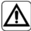
1.1 - LIST OF THE COMPONENTS SUPPLIED
The units making up the climate control system are packaged individually in cardboard boxes.
Individual unit packages can be transported by hand by two members of personnel, or loaded onto a transport trolley; up to max. three packages stacked for indoor units and individually for outdoor units.
Before beginning to assemble the unit, make sure all the parts are within easy reach.
A. Appliance UNICO PRO EVAN
T1. Remote control
C. Use and maintenance book-lets + warranty
D. Strip of adhesive isolating tape (x 2)
E. Kit of screws and anchor bolts
F. Air inlet and outlet external grids including chains and kit for installing the grids (x 2)
G. Internal flanges (x 2)
H. Sheet for wall pipes (x 2)
L. Bracket for wall anchoring
M. Paper template to make holes
N. Condensation drain pipe
O. Purifying filter (green colour)
P. Active carbon filter (black colour)
The batteries (T3) for the remote control, quantity 2 - 1,5V AAA type, are components necessary but not supplied as a standard.
1.2 - STORAGE
Store the cartons in a closed environment protected against atmospheric agents and raised off the floor by planks or a pallet.

DO NOT TURN THE PACKAGING UPSIDE DOWN NOR PLACE IT HORIZONTALLY.
1.3 - RECEIPT AND UNPACKING
The packaging is made up from suitable material and performed by expert personnel. The units are delivered complete and in perfect condition. However, for he quality control of the transport services, follow the warnings below:
a. On receipt of the packages, check whether the packaging is damaged. If this is the case, withdraw the goods with reserve, producing photographic proof and any apparent damage.
b. Unpack, checking the presence of the individual components with the packing lists.
c. Control that all components have not undergone damage during transport. If this is the case, inform the carrier by registered letter with acknowledgement of receipt within 3 days of receiving the goods, presenting photographic documentation.
d. Pay attention when unpacking and installing the equipment.
Sharp parts can cause injury. Pay particular attention to the edges of the structure and the fins of the condenser and evaporator.

No information concerning damage undergone can be taken into consideration after 3 days from delivery.
For any controversy the court of jurisdiction will be BRESCIA.

Keep the packaging for at least the duration of the warranty period, for any shipments to the after-sales centre for repairs. Dispose of packaging in compliance with the regulations in force regarding waste disposal.
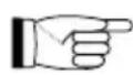
1.4 - APPLIANCE COMPONENTS DESCRIPTION (fig.A)
- Air outlet deflector (Flap)
- Alarms and function visualization console
- Air intake grille
- Air filter
- Condensation drain and emergency drain access door
- Serial port access door
- Power cord
2 - INSTALLATION
2.1 - INSTRUCTIONS FOR INSTALLATION
To obtain the best results and optimum performance, follow the instructions for correct installation provided in this manual.
A failure to implement the indicated standards, which may cause a malfunction of the appliances, relieves OLIMPIA SPLENDID from any form of warranty and from any liability for possible damages caused to people, animals or things.
The electrical system must be compliant with legal standards, must respect the data in the technical data sheet and be must be equipped with an efficient ground system.
2.2 - SIZE AND SPECIFICATIONS OF THE ROOM IN WHICH TO INSTALL THE AIR CONDITIONER
- Before installing the air conditioner, it is essential to make an accurate calculation of the heat load in summer (and cold load in winter for models with heating pump) at the site of installation.
- The more accurate this calculation is made the better the air conditioner will be able to do its job.
- When executing the calculations, refer directly to the prevailing standards.
EN - 14
- For particularly important applications, we recommend contacting expert heating engineers.
- The user should try to limit high heat loads as much as possible as follows: glass doors and windows exposed to many hours of sunlight should be fitted on the inside with curtains or, even better, on the outside with coverings such as Venetian blinds, verandahs, refractive film, etc.). The air-conditioned room must remain closed as long as possible.
- Halogen spotlights or other electrical equipment with high power consumption should not be used in the room (toasters, steam irons, hot plates for cooking, etc.).
2.3 - CHOOSING THE POSITION OF THE UNIT
To obtain the best operating performance and prevent faults or hazardous conditions, the position of indoor unit installation must meet the following requirements:
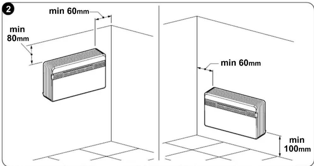
a. Do not expose the appliance to heat or steam sources (fig. 3).
b. Make sure that the space to the right and left is at least 60 mm and space above the unit is at least 80 mm. (fig. 2).
c. The height of the unit's lower edge from the floor should be at least 100 ~mm if fixed to the wall in the lowest position. If fixed to the wall in the highest position, it should be at least 80 ~mm from the ceiling (fig. 2).
d. The wall where the indoor unit is to be fixed, must be stable, strong and suitable to support the weight.
e. It must be possible to leave room around the unit for any maintenance operations that may be necessary.
EN - 15
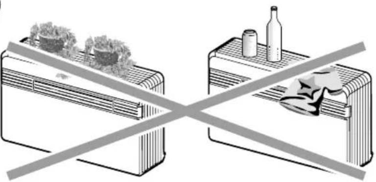
f. Nothing should be in the way of the air that needs to circulate both on the top air-intake (curtains, plants, furniture) and at the front where the air exits. This could cause air swirls that would inhibit the working efficiency of the unit (fig. 3).
g. Do not spray water or other liquids of any kind directly on the unit (fig. 3).
h. The appliance must not be positioned so that the air flow is directed directly towards nearby people (fig. 3).
i. Never force the opening of the airflow flap (fig. 3).
I. Do not place bottles, cans, clothes, flowers or any other object on the air suction grille (fig. 3).
m. Do not install the air conditioner directly on another household appliance (TV, radio, fridge, etc.), or on a heat source (fig. 3).
3
natural_image
Two crossed-out air conditioner units with a diagonal line crossing, one emitting exhaust smoke (no text or symbols)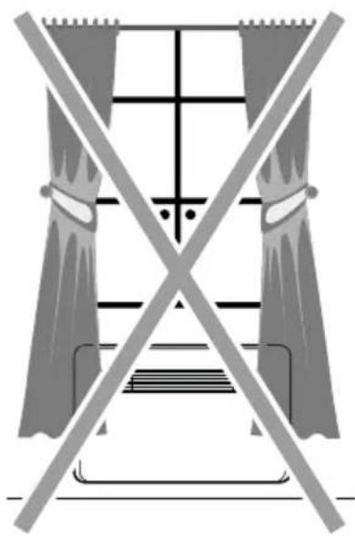
natural_image
Pure electrical circuit lines without any symbols
natural_image
Diagram showing two containers with a hand holding a small object, separated by a diagonal line crossing over a bottle (no text or symbols present)
natural_image
Illustration of a double boiler with steam rising from its chimney, crossed out by a diagonal line (no text or symbols)
natural_image
Illustration of a woman at a desk crossed out by a crossed-out 'No' symbol, with no text or symbols present.EN - 16

The air conditioner must be installed on a wall that communicates with the outside
After determining the best place for installation as described above, check for the absence of other structures or systems (beams, piers, pipes, wires, etc.) at the points where the holes are to be drilled, which would prevent drilling the holes required to install the unit.
Check again to make sure there are no obstacles to air circulation through the holes to be drilled due to plants and their leaves, slats or panelling, blinds, gratings or grids too dense, etc.).
2.4 - UNIT ASSEMBLY
The maximum length allowed for the pipes is 1 m, the pipes must be internally smooth and no bends can be made.
It is necessary to use the grilles provided, or grilles which keep the same features.
2.4.1 - Drilling the wall
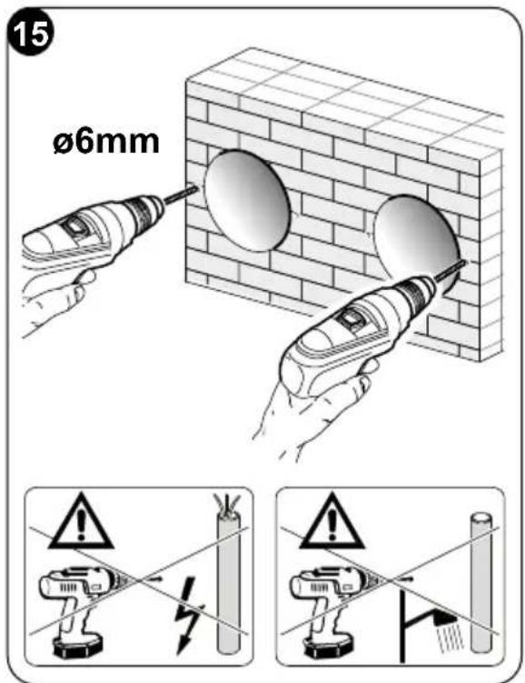
To operate, the unit requires two holes to be drilled in the wall, positioned as indicated on the drilling template; the holes can have both a 162 mm and 202 mm diameter.
- It is possible to install the unit UNICO PRO EVAN instead of a unit UNICO SKY, UNICO STAR, UNICO SMART or UNICO INVERTER without modifying the already existing holes, exception made for the small condensation drain hole. In this case, in order not to penalize performances, remove the insulating material possibly present in the air expulsion hole. The anchoring brackets need new drilling too.
- Drill the wall using the proper tools to facilitate your job and prevent excess damage or disturbance to your client.
The best tools for drilling large holes in walls are special drills called core borers with very high twisting torque and adjustable rotating speed depending on the diameter of the hole to be drilled.
- To prevent the creation of large amounts of dust and rubble due to drilling, the core borer can be fitted with a vacuum system applied by means of suction cups to the drilling zone.
• To drill the holes, proceed as follows:
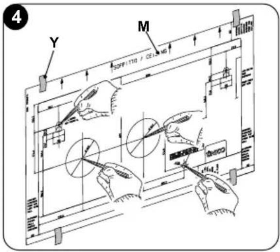
- Place the supplied drill jig (M) against the wall observing the minimum distances from the ceiling, the floor and from the side walls indicated on the jig itself which can be kept in the correct position using adhesive tape (Y) (fig. 4).
- Use a small drill or punch to mark, with extreme care, the exact centre of each of the holes to be drilled (fig.4).
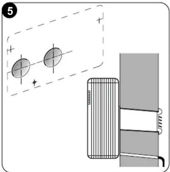
- Using a core boring head measuring at least 202 mm (or 162 mm) to drill the two holes for entry and exit of the air.
Drill the foregoing holes tilted slightly downwards to prevent water from being fed back through the ducts (fig. 5).
Most of the removed material is expelled outwards, therefore make sure that it does not hit any person or object when it falls out.
In order to avoid as much as possible outer plaster breaking, it is necessary to proceed carefully with the last part of hole execution, decreasing pressure on core borers.
- Drill the holes, previously marked, for the wall plugs related to the fixing brackets (fig. 6).
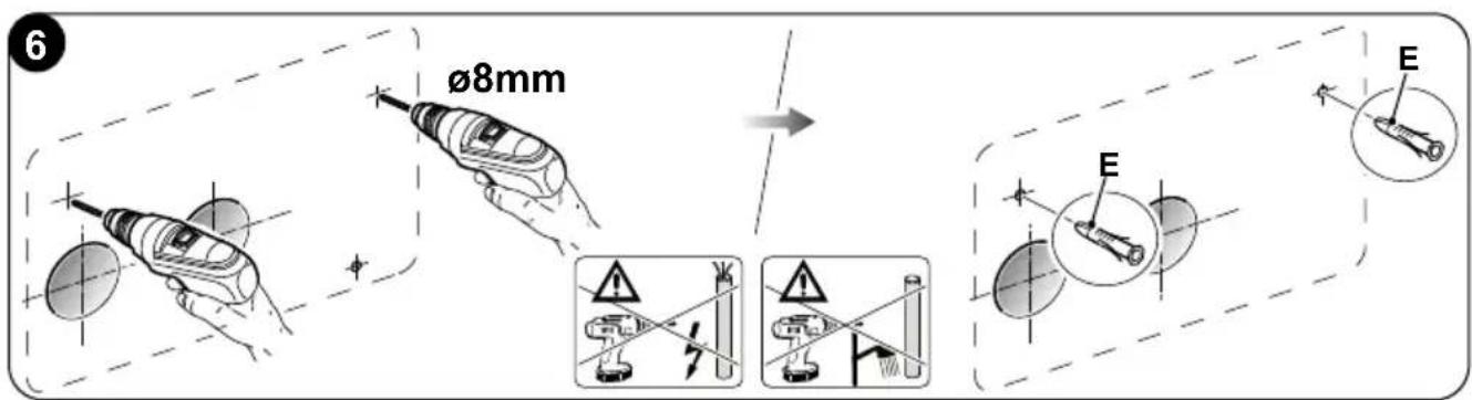
EN - 18
Carefully check the characteristics and consistency of the wall in order to possibly choose wall plugs specific for particular situations.
The manufacturer will not be held liable for any underestimates made in the structural consistency of the anchor prepared by the installer. Therefore, pay utmost attention to the foregoing operation that could cause serious injury/damage to people/property if carried out incorrectly.
- When installing models equipped with heating pump, if no condensate discharge was built into the wall (see paragraph 2.4.2), in order to drain the condensate it will be necessary to drill a hole through the wall in the position shown on the template.
2.4.2 - Preparing the condensate discharge
- For machines with heat pump, a condensation drainage tube (N), to be grafted in the specific receptacle (X) to which you access after opening the door (5) underneath the unit, must be connected to the air conditioner. Remove the cap (B) (fig. 7) before inserting the condensation drain pipe.
When the max level is reached, a solenoid valve ensures the condensate will flow out from the internal tray.
- For cold-only machines, connect the condensate discharge pipe if you intend running the unit at low outdoor temperatures (lower than 23°C).
- Since condensate drains by gravity, there must be a minimum slope of at least 3% at every point of the discharge line. Use a rigid or flexible tube having an inside diameter of at least 16 mm.

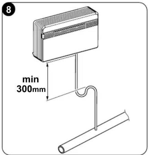
- If the line empties into a sewerage system, install a siphon before the point in which the pipe reaches the main discharge, at least 300 mm below the inlet from the unit (fig. 8).
EN - 19

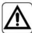
- If the drainpipe drains into a vessel (tank or other container), this container should not be sealed and the drainpipe should not remain immersed in the water (see fig. 9).
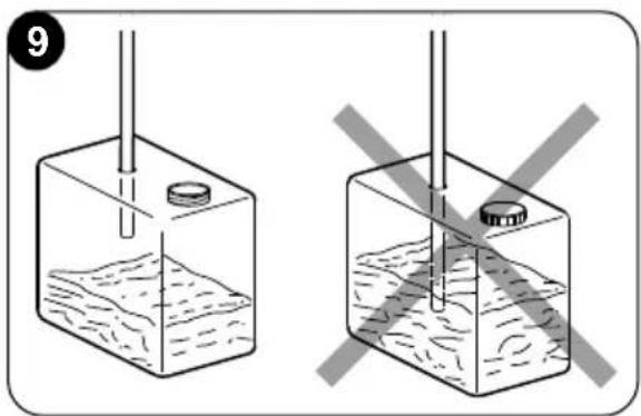
- The hole (J) through which the condensate pipe passes should always slope towards the outside (see fig. 10).
The exact position in which to place the pipe inlet, as compared to the machine, is shown on the drilling template.
Make sure, in this case, that the water expelled outward does not damage or disturb persons or property.
During the winter this type of drainage may cause sheets of ice to form.
When the condensate drainage is fitted, pay much attention not to compress the rubber hose.
In the event of operation during the winter with temperatures equal to or lower than 0^ C, make sure that the condensate drain pipe is protected from freezing in order to ensure draining.
In the event of prolonged operation during the winter with temperatures below 5°C, install the optional basin heater kit.
2.4.3 -Assembly of the air ducts and external grids
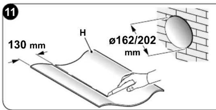
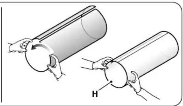
• After drilling the holes (with the core drill), insert the plastic sheet (H) supplied with the air conditioner (fig. 11) inside them.
Since the sheet (H) was made for 202 mm holes, you will have to cut off 130 mm from the long side of the sheet for the 162 mm holes (fig. 11).
The sheets must be 65 mm shorter than the length of the wall.
EN - 20
natural_image
Illustration of two hands holding a cylindrical object with a circular component, labeled 'H' (no text or symbols on the objects themselves)- Roll the sheet (H) and insert it into the hole, paying attention to the splicing line, which must always face upwards. (fig.11).
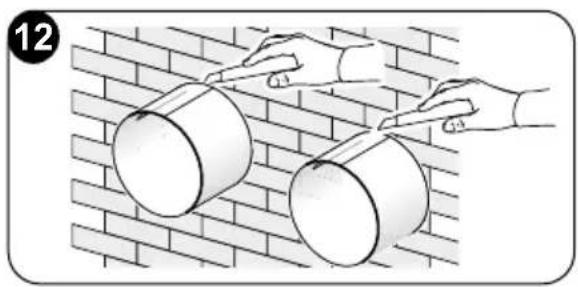
Use an ordinary cutter for the foregoing operation (fig. 11 - 12).
natural_image
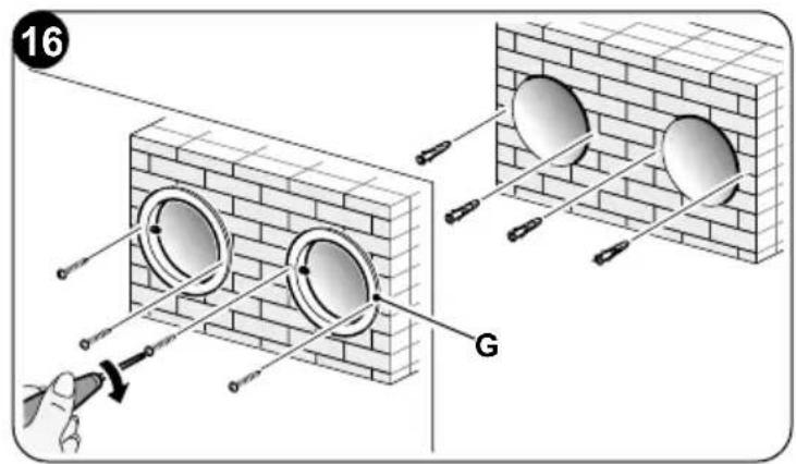
Illustration of two hands painting cylindrical objects on a brick wall (no text or symbols)To position the external grids, proceed as follows:
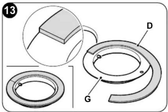
a. Apply the seal (G) to the wall flange (D), ensuring it lines up with the outer edge of the flange as indicated in the figure 13.
b. Fix the two flanges using 2 pegs having a diameter of 6 mm and check that the two fixing holes are horizontal (fig. 14 - 15 - 16).

EN - 21
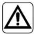
c. Fit the small eyelet of the spring, with the long stem, on the cap pin (on both components) (fig. 17).
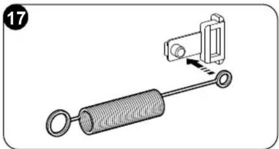
d. Insert the two caps (with spring), on the front part of the external grid, on its two housings, pulling until it clicks (fig. 18) and couple the two chains to the large eyelet of the spring.
e. Using one hand, grip the two chains connected to the grid;
f. Bend the external grids back, gripping them with your free hand where they bend, and insert your fingers inside the single fins (fig. 19).
g. Insert your arm into the pipe until the grid protrudes completely outwards.
h. Reopen the grid, being careful to keep your fingers inside the fins.
i. Turn the grid until the fins are fully horizontal and tilted downwards.
I. Pull the chain, tensioning the spring, and couple the chain ring to the pin of the inner flange through which the pipes pass (fig. 20).
m. Use hand shears to cut off any excess chain links.
Use exclusively the supplied grids (F), or grids with like characteristics.

natural_image
Illustration of a hand using a mechanical device to interact with chains (no text or symbols visible)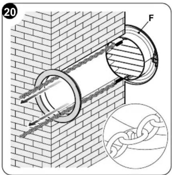
2.4.4 - Preparing the holes on the machine
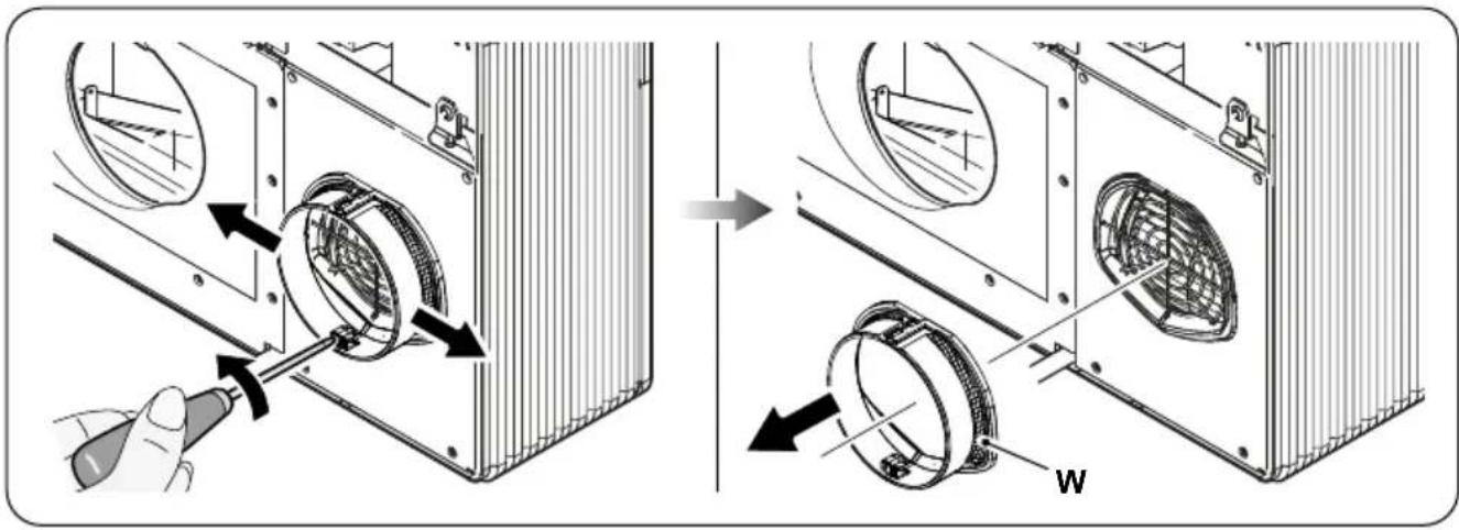
If 162 mm pipes are being used, the removal operation of part of the rear cover must not be performed.
The fan extension cord (W) must be removed as shown below.
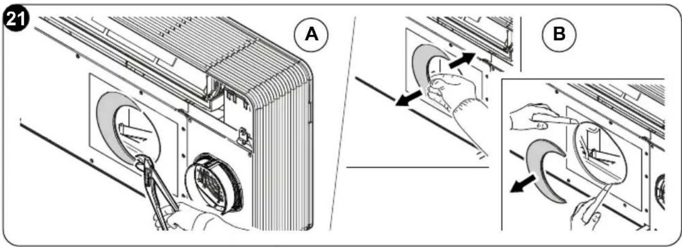
In the event of use of ∅ 202 mm holes, work as follows:
a. Use pincers to break the precut of the rear cover (fig. 21-A).
b. Then, rotate back and forth the part of the cover to be remove with the hand until breaking the remaining precut part (fig. 21-B).
c. Use a cutter to trim the possible insulating material in excess which remained inside the hole (fig. 21-B).
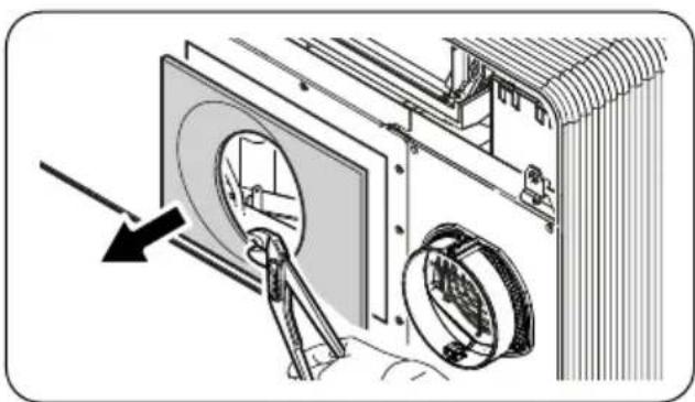
The rear cover is also prepared for the rectangular intake channel. If this type of installation is preferred, break the rectangular precut and use an intake grille of a size suitable for the intake channel.
natural_image
Mechanical assembly diagram showing a device with a circular component and a pulley, no text or symbols presentEN - 23
2.4.5 - Positioning of the device on the anchor bracket
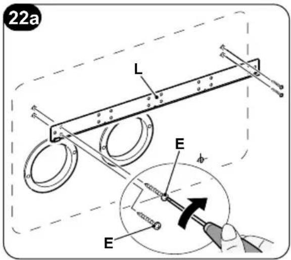
Working on the two previously drilled holes (see fig. 6), fix the support bracket (L) to the wall using the supplied wall plugs screws (H) (fig. 22a).
After checking:
that the fixing bracket is well anchored to the wall,
that the installation site has been prepared for electrical connection and condensation discharge (if necessary), is possible to hook the air conditioner.
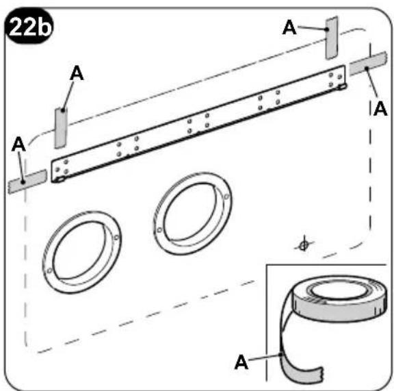
Work as follows:
a. Apply adhesive tape (A) to have references to the hooking points of the unit (fig. 22b).
The tape can be removed once the unit has been hooked to the wall.
b. Lift the air conditioner by holding it on the sides of the lower base and hook it to the bracket (L) (fig. 23).
Slightly tilt the lower part of the appliance towards yourself to ease the operation.


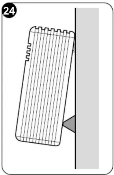
- To make the electrical connection and fasten the drainpipe, place a wedge between the air conditioner and the wall (see fig. 24).
- When you have finished, inspect carefully to make sure there are no fissures at the back of the air conditioner (the insulating gasket must fit firmly against the wall) particularly in the zone where air enters and leaves the machine.
natural_image
Diagram of a mechanical component with a triangular cutout and a shaded section, no text or symbols present2.5 - ELECTRIC HOOK-UP
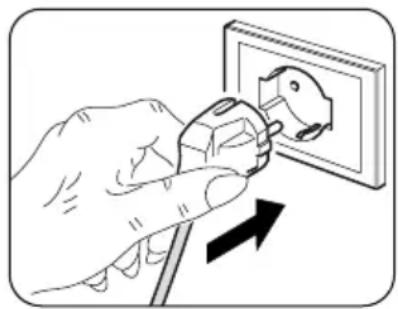
The appliance is fitted with a power cord with plug (Y-type connection).
If the socket is in proximity to the appliance, simply plug it in.
natural_image
Illustration of a hand using a power plug to switch an electrical outlet (no text or symbols present)
Before connecting the conditioner, ensure that:
the power supply voltage and frequency values comply with those indicated on the data plate of the appliance.
- The power supply line is fitted with an efficient earth connection that is appropriately sized for the maximum absorption of the conditioner (minimum cross-section of the cable must be 1.5 mm ^2 ).
- The appliance is powered exclusively through a socket that is compatible with the plug supplied.

Any replacement of the power cable must be carried out solely by authorized technical support or by similarly qualified personnel.
On the power supply line of the appliance there must be an adequate omnipolar disconnection device that complies with the national installation regulations. It is, however, necessary to check that the electrical power supply is equipped with efficient earthing and with adequate protections against overloading and/or short circuits (a type 16 AT delayed fuse or other devices with equivalent functions are recommended).
EN - 25

It is possible to proceed with the electric connection through a cable recessed into the wall in the position indicated in the installation template (connection advised for installations of the equipment in the top part of the wall).
To prevent any risk of electrocution, it is fundamental to disconnect the main power switch before carrying out electrical connections and any maintenance operation on the appliances.
To replace the power cord, proceed as follows:
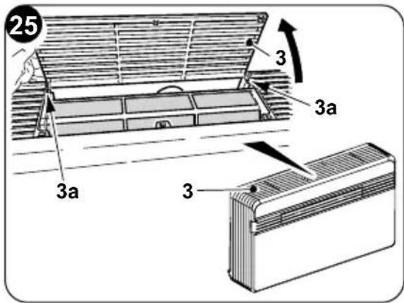
a. Raise the air intake grille (3) and remove the two screws (3a) (fig. 25).
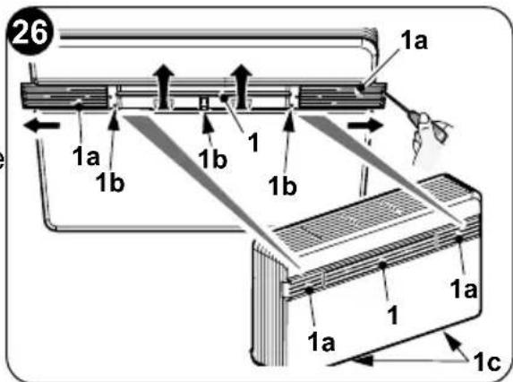
b. Extract the right (unlock with a screw-driver) and left (1a) doors of the front cover, then turn the flap (1) and remove the three screws (1b) and the two screws (1c) (fig. 26).
c. Remove the front cover.
d. Undo the two fixing screws (X2) to remove the front cover of the switchgear (X1) (fig. 27).
e. Undo the two fixing screws (X4) to remove the top cover of the switchgear (X3) (fig. 27).
f. Unscrew the cable clamp (J1) and the cable locking screws of the clamp block (J2) (fig. 28)
g. Extract the cable and insert the new cable by following the same path.
h. Lock the three poles of the cable in the clamp block (J2) and tighten the screws.
i. Lock the cable with the clamp (J1).
I. Close the switchgear.
m. Reassemble the front cover of the machine.
This operation must be carried out by specialized personnel possessing the skills required by law.
To change configurations, proceed as follows:
a. Insert the plug into the power socket to feed the air conditioner, then make sure the latter is set to stand-by mode.
b. Keep the MODE key pressed for approximately 10 seconds until the display shows the parameter PO.
c. Press the + or - keys to select the parameter value to be set (from P0 to P4).
d. Keep the MODE key pressed for approximately 2 seconds until the parameter flashes.
e. Press the keys + or - to select the desired value.
f. Press MODE to confirm the desired value.
g. Press the Standby key or wait approximately 20 seconds to leave the parameters configuration procedure.
2.6.1 - Configuration of the electronics for low or high wall installation
The unit can be installed both in the lower part (adjacent to the floor) and in the upper part (adjacent to the ceiling) of the wall.
To optimize air distribution and ambient comfort, the direction of the air flow can be changed by changing the position of the air outlet flap.
Upper wall configuration determines an automatic correction of the room temperature equal to 3^ C in heating mode.
For correct functionality, each modification of the configuration of the air outlet flap must correspond to the relative modification of the electronic configuration.
In the configuration of high or low wall installation, the display shows 1.
To set the desired configuration, carry out the previously described procedures and choose between the parameter uP (for roof installation) or (for floor installation).
2.6.2 - Energy boost/System enable configuration
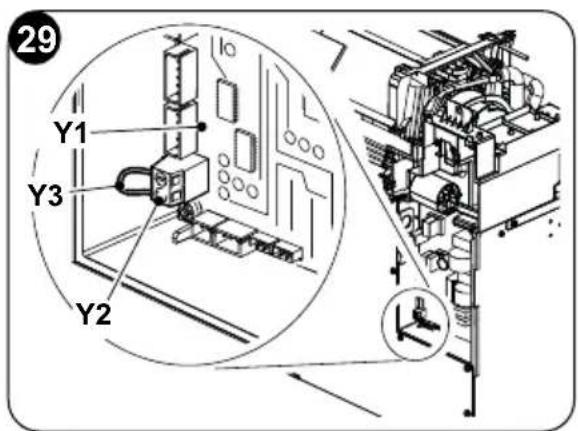
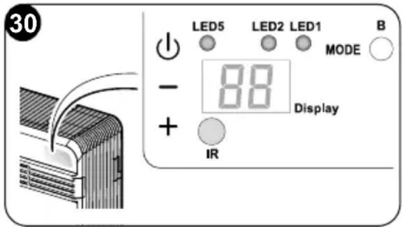
The inlet located on the clamp (Y2) of the main board (Y1) can be used to activate the ENERGY BOOST or SYSTEM ENABLE functions of the air conditioner (fig. 29).
EN - 27

In the configuration of the contact Energy boost or System enable, the display shows . The parameter can possess a value included between -5 and +5.
With value PI = 0, the inlet works from SYSTEM ENABLE.
When the contact opens, the air conditioner is forced in stand-by mode.
When the contact closes, the air conditioner restores the previous operating status.
With value PI ≠ 0, the inlet works from ENERGY BOOST.
Values <0 reduce the Tset in cooling, increasing machine power (for instance, if T_set=24^ and Energy boost = -3^ , the machine works as if the Tset is 21^ )
Values >0 increase the Tset in heating, increasing machine power (for instance, if T_set=24^ and Energy boost = 3°C, the machine works if the Tset is 27^ )
To configure the appliance at the activation of one of the two functions, proceed as follows:
a. Raise the air intake grille (3) and remove the two screws (3a) (fig. 25).
b. Extract the right (unlock with a screwdriver) and left (1a) doors of the front cover, then rotate the flap (1) and remove the three screws (1b) (fig. 28).
c. Remove the front cover.
d. Undo the two fixing screws (X2) to remove the front cover of the switchgear (X1) (fig. 27).
e. From the screw clamp (Y2), remove the supplied bridge (Y3) (fig. 29).
f. Close the switchgear.
g. Reassemble the front cover of the machine.
The inlet must be driven by a potential-free contact.

Do not use a cable longer than meters 10.
2.6.3 - Input setting configuration
In the configuration of the open or closed contact, the display shows
To set the desired configuration, carry out the previously described procedures and choose between the parameter NC (closed contact) or (open contact).
2.6.4 - Temperature unit of measurement configuration
In the configuration of the unit of measurement of temperature, the display shows. To set the desired configuration, carry out the previously described procedures and choose between the parameter (metric system) or (imperial system).
2.6.5 - Heat pump / only cooling / only heating configuration
During configuration of the mode of operation of the unit, the display shows
To set the machine so as that it works both in cooling and in heating mode, select the "HP" configuration (heat pump).
EN - 28
To set the machine so as that it works in cooling mode only, select the "CO" configuration (cooling only).
To set the machine so as that it works in heating mode only, select the "HO" configuration (heating only).

Only in the event of the machine set to “CO” mode it is possible to not envisage the unloading of condensation of the machine. During installation phase, make sure the machine does not have the setting for heating mode by means of the remote control/display/app.
3 - USE
3.1 - WARNINGS
The installation and electrical connection of the air conditioner should be carried out by specialized personnel who possess the requisites set forth by law.
The installation instructions are contained in the appropriate paragraph of this manual.
No structural object (furniture, curtains, plants, leaves, blinds, etc.) should ever obstruct the normal flow of air from either the internal or external gratings.
- Never lean or, worse yet, sit on the casing of the air conditioner as this could cause serious damage to the external parts.
- Do not move the air outlet flap by hand. Always use the remote control to adjust baffle position.
- If the unit leaks water, switch it off immediately and disconnect it from the power mains. Call the nearest service centre.
- When the air conditioner is heating, it has to periodically eliminate any ice that could form on the external battery. While it is doing this, the machine keeps running but does not heat the room. This lasts for a brief period of time, from 3 to a maximum of 10 minutes.
- Clean the air filter periodically, as described in the specific paragraph (5.1.2).

The air conditioner must not be installed in rooms where explosive gasses develop or where there are conditions of heat and humidity beyond the maximum limits indicated in the installation manual.
3.2 - DESCRIPTION OF THE WARNING PANEL
In the top right part of the appliance are located some buttons and LEDs led whose functions are described below.
Buttons
Before carrying out the following operations, press one of the keys to enable the console.
- Desired temperature increase (maximum settable value 30°C/86F).
- Desired temperature decrease.
(minimum settable value in heating mode 16^ C/61F, in cooling mode 18^ C/64F).
Activation/deactivation (Stand-by) of the air conditioner and selection of the fan speed.
- Brief touch to select the minimum, medium, maximum or automatic fan speed.
- Prolonged touch for activation/deactivation (Stand-by).
MODE Selection of the mode of operation and parameters setting
- Brief touch (for more than 2 seconds) to select the fan, cooling or heating operating mode
- Prolonged touch to enable parameters setting if in Stand-by
+ e - To be pressed simultaneously for at least 5 seconds to enable/disable the keyboard lock

e MODE
To be pressed simultaneously and in a prolonged manner (for at least 5 seconds) to reset the dirty filter report
Others
IR Infrared receiver
B Acoustic signaller
| OPERATING CONDITIONS | DISPLAY (white) | LED2 wifi (green) | LED1 mode (red/blue) | LED5 timer (white) |
| Stand-by | OFF | ON(*) | OFF | OFF |
| Cooling mode | 18÷30°C/64÷86F | ON(*) | BLUE | X |
| Heating mode | 16÷30°C/61÷86F | ON(*) | RED | X |
| Dehumidification mode | -- | ON(*) | BLUE | X |
| Fan mode | -- | ON(*) | OFF | X |
| Automatic mode | R | ON(*) | X | X |
| Timer enabled | X | ON(*) | X | ON |
EN - 30
| OPERATING CONDITIONS | DISPLAY(white) | LED2wifi(green) | LED1mode(red/blue) | LED5timer(white) |
| Low wall or high wall configuration parameter | P0 | OFF OFF | OFF | |
| Roof installation | P | OFF OFF | OFF | |
| Floor installation | d0 | OFF OFF | OFF | |
| Input setting | P2 | OFF OFF | OFF | |
| Energy Boost/ System Enable contact opening | nc | OFF OFF | OFF | |
| Energy Boost/ System Enable contact closure | no | OFF OFF | OFF | |
| Input setting | AP | Lampeggio | OFF OFF | |
| Filter dirty | F1 | X X X | ||
| ON (*) = Connected | ||||
3.3 - USE OF THE REMOTE CONTROL
The remote control supplied with the air-conditioner is the instrument that enables you to use the appliance in the most convenient way.
It should be handled with care and in particular:
- Keep it dry (do not clean it with water or leave it outdoors in bad weather).
- Avoid dropping or bumping it.
- Keep it out of direct sunlight.
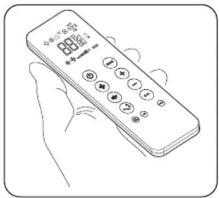
- The remote control operates by means of an infrared beam.
- During use, there must not be any obstacle between the remote control and the air-conditioner.
- If other appliances in the room have remote controls (TV, stereo, etc...), there may be interference with consequent loss of the sent signal.
- Electronic and fluorescent lights may also interfere with transmissions between remote control and air-conditioner.
- Remove the batteries in case of prolonged disuse of the remote control.
- The remote control display goes off after a few seconds of non-use, to reactivate it press any key.
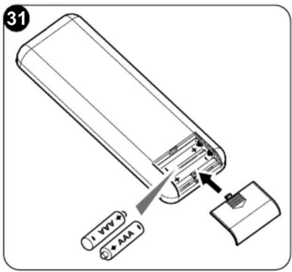
3.3.1 - Insertion of batteries (fig. 31)
To insert the batteries correctly:
a. Remove the batteries compartment cover.
b. Insert the batteries into the relevant compartment.
Check the polarity indicated on the bottom of the compartment.
c. Close the compartment correctly.
3.3.2 - Replacement of batteries
The batteries should be replaced when the display on the remote control does not appear sharply or when the remote control does not change the settings.
Always use new batteries and replace both at the same time.
The use of old or different batteries could generate malfunctioning of the remote control.
The remote control uses two dry alkaline 1.5V batteries (AAA.LR03) (fig. 31). When the batteries have been replaced, adjust the remote control clock.
When replacing batteries, replace both and dispose of the dead batteries in the appropriate collection centres and as required by law.
- If the remote control is not used for several weeks or longer, remove the batteries. Any leaks from the batteries could damage the remote control.
- The average life-span of the batteries, with normal use, is approx. six months. Replace the batteries when the indoor unit command receipt "beep" can no longer be heard, or if the transmission indicator on the remote control does not switch on.

Do not re-charge or disassemble the batteries. Do not throw the batteries into the fire. They can burn and explode.
If the battery liquid falls onto the skin or clothes, wash well with clean water. Do not use the remote control with batteries that have leaked. The chemical products contained in the batteries can cause burns or other risks to health.
EN - 32
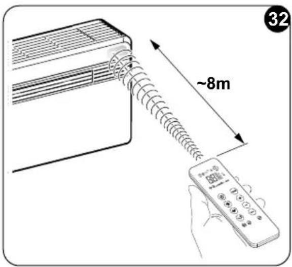
3.3.3 - Location of the remote controller
- Keep the remote control in a position from which the signal can reach the appliance receiver (maximum distance is about 8 meters - with charged batteries) (fig. 32). The presence of obstacles (furniture, curtains, walls, etc.) between the remote control and the appliance reduces the remote control range.
3.4 - DESCRIPTION OF REMOTE CONTROL
The remote control is the interface between the air-conditioner and the customer, so it is very important to learn all its functions, the use of the various controls and the meaning of the symbols marked on it.
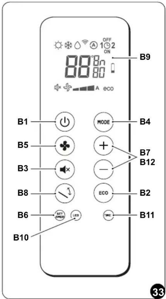
3.4.1 - Description of the remote control keys (Fig. 33)
B1 Activation/deactivation (Stand-by) of the unit
B2 ECONOMY/ECO mode key
B3 Night mode key SILENT
B4 Operating mode selection - cooling
heating > ventilation > dehumidification > automatic
B5 Increase/decrease fan speed
B6 Clock/programming setting
B7 Increase/Decrease desired temperature/clock/programming
B8 Activation/deactivation of the oscillation function of the air outlet flap
B9 Display
B10 Activation/deactivation of switching on of the display on board of the machine
B11 Activation/deactivation of programs
B12 Selection of the desired temperature unit °C / °F by pressing keys B7 simultaneously
EN - 33
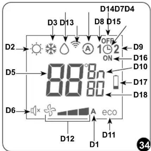
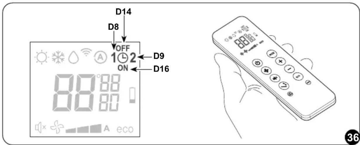
3.4.2 - Description of the remote control display (Fig. 34)
D1 Indication of the fan speed or its automatic operating mode (AUTO)
D2 Heating mode
D3 Cooling mode
D4 Dehumidification mode
D5 Desired temperature/clock/programming
D6 Night function (SILENT)
D7 Automatic function
D8 Program 1
D9 Program 2
D10 Temperature/clock indicator
D11 ECO function enabled
D12 Minimum - average - maximum ventilation speed
D13 Transmission of the command in progress
D14 Program switching off time setting
D15 Clock/program setting
D16 Program switching on time setting
D17 Low battery notification
D18 Minutes timer
3.5 - DESCRIPTION OF THE AIR CONDITIONER FUNCTIONS
3.5.1 - Main switch-on and running management
- The machine may be regulated using the remote control.
In order to transmit commands to the indoor appliance, point the front of the remote control toward the appliance's control panel.
The device emits a beep when it receives a command.
- The maximum distance from which the appliance can be controlled is about 8 meters (with charged batteries).
3.5.2 - ECO key
- Pressing the B2 key on the remote control activates the energy saving function, automatically optimizing the machine functions, the D11 symbol appears on the display.
3.5.3 - Turning the unit ON/OFF
- Press key B1 on the remote control to activate or deactivate (stand-by) the air conditioner.
The control system of the unit is equipped with memory, for this reason all the settings won't be lost when shutting off the appliance itself.

In case of prolonged stop of the machine, it must be deactivated turning the main switch off or unplugging the machine from the mains.
3.5.4 - Operation in "Cooling" mode only
- When used in this mode, the air conditioner dehumidifies and cools the room.
- To activate this mode, press the key B4 on the remote control several times until the D3 symbol appears on the display.
- In this run mode, the required temperature and fan speed can be set.
After three minutes (as a maximum) from activation in this operating mode the compressor will start and the appliance starts emitting cold air.
3.5.5 - Operation in "Dehumidification" mode only
- When used in this mode, the air conditioner eliminates the humidity in the room. This function can be extremely useful between seasons, particularly on rainy days when the temperature is not uncomfortable but the excess humidity feels unpleasant.
- In this mode, both room temperature and fan speed settings are ignored, which correspond to minimum.
- Then, any indication of temperature and speed of the fan disappears from the display of the remote controller and from the control panel.
- To activate this mode, press the B4 key on the remote control several times until the D4 symbol and the D1 (fan plus first notch) automatic ventilation symbol appear on the display.
- In this operating mode it is normal for the air conditioner to function intermittently.
3.5.6 - Operation in "Ventilation" mode only
- When used in this mode the air conditioner does not perform any action with regard to temperature and air humidity in the room.
- To activate this mode, press key B4 on the remote control several times until the automatic ventilation symbol D1 (fan plus first notch) appears on the remote control display.
3.5.7 - Operation in "Spa" mode only (Automatic)
- In this mode, the machine's temperature is automatically regulated according to the room's temperature. The fan speed is also automatically regulated according to the set temperature (except in dehumidification mode).
EN - 35
- To activate this mode, press the B4 key on the remote control several times until the D7 symbol appears on the display.
3.5.8 - Operation in "Heating" mode only (only models fitted with heating pump)
• Using this mode, the appliance heats the room.
This function is only available for the versions with heat pump (HP).
- To activate this mode, press button B4 on the remote control several times until the D2 symbol appears on the display.
- In this run mode, the required temperature and fan speed can be set. After three minutes (maximum time) the compressor should start and the air conditioner starts heating the room.
The air conditioner has to defrost its battery periodically.
During this operation the air conditioner does not heat the room, though its internal parts remain on except for the room air fan. when the outdoor temperature is very low, there may be a slight delay for passage from the minimum to the medium or maximum speed from when the command is sent to the machine with the remote control.
Like delays might occur on activating the swinging function of the mobile baffle.
After having turned off the unit, the internal fan runs seconds more. Then it stops and both air flaps close.
3.5.9 - Checking airflow direction
- Press key B8 on the remote control to activate/deactivate the continuous oscillation of the moving air outlet deflector (1).
- When continuous oscillation is active, an additional press of the key B8 allows to lock the deflector so as to obtain the desired vertical direction for the air flow.
The moving deflector position must never be forced manually.
- The fan speed check occurs through key B5 (on the remote control).
- Pressing several times this key will cause speed to change according to the following sequence:
$$ \text { Low } > \text { Medium } > \text { High } > \text { Automatic }. $$
- The higher the speed setting, the greater the output of the air conditioner but also the louder its operation.
- By setting the Automatic mode, the onboard microprocessor adjusts the automatic speed. The higher the difference between the room temperature detected and the temperature set, the higher the speed.
- As the room temperature nears the setting, fan speed is reduced automatically.
- In dehumidification mode, it is not possible to control the speed as the appliance can only operate exclusively at low speed.
3.5.11 - SILENT key
- To activate this mode, press the B3 key on the remote control, the D6 symbol appears on the display.
-
Activating the SILENT allows you to obtain multiple results:
-
gradual increase in the set temperature during cooling mode
- gradual decrease in the set temperature for heating (HP versions only)
- reduction of the sound level of the appliance
-
decrease of the fan speeds
-
For activation of the SILENT function, it is first necessary to select the operating mode and the desired temperature, then activate the SILENT function by pressing the key B3.
- Noise reduction entails an optimization of noise and thermal/cooling capacity of the machine. In the event that, in some moments, the thermal/cooling power is insufficient, deactivate the SILENT function.
3.5.12 - Timer setting
- The appliance logic allows the User to make use of two different timer programs (see paragraph 3.5.14), thanks to which the appliance can be deactivated and activated (or vice versa) whenever desired (for example, it can be activated shortly before returning home so as to find an already pleasant temperature in the room).
- Firstly, if it is desired to make use of these functions, set the correct time (see paragraph 3.5.13) and then set the timer as you prefer.
3.5.13 - Timer and clock setting
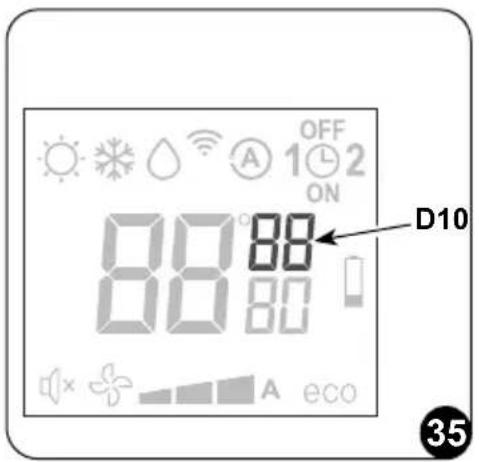
To set time, work with the remote control as follows (fig.35):
a. Press key B6 (SET TIMER) until when the hour indication h (D10) appears on the display
b. Set the hour with keys B7 (+ and -).
c. Press the key B6 until when the minutes indication m (D10) appears on the display.
d. Set the minutes with keys B7 (+ and -).
e. Press key B6 to save the time and proceed with the timer programming.
3.5.14 - Timer setting (PROGR. 1 and PROGR. 2) (T2)
It is possible to set one or both the timer programs.
To set the appliance activation and deactivation times in the two programs, use the remote control and work as follows (fig.36):
a. Press once or more key B6 (SET TIMER) until when symbol 1 (D8) (Activation time of the 1^ program) and symbol ON (D16) appear on the display.
b. Use keys B7 (+ and -) to increase or decrease the hour in which you wish the air conditioner activates.
The hour variation settable with keys B7 (+ and -) is of 30 minutes.
c. Press key B6 (SET TIMER) a second time; symbol 1 (D8) (Deactivation time of the 1^ program) and symbol OFF (D14) appear on the display.
d. Use keys B7 (+ and -) to increase or decrease the hour in which you wish the air conditioner switches off. The hour variation settable with keys B7 (+ and -) is of 30 minutes.
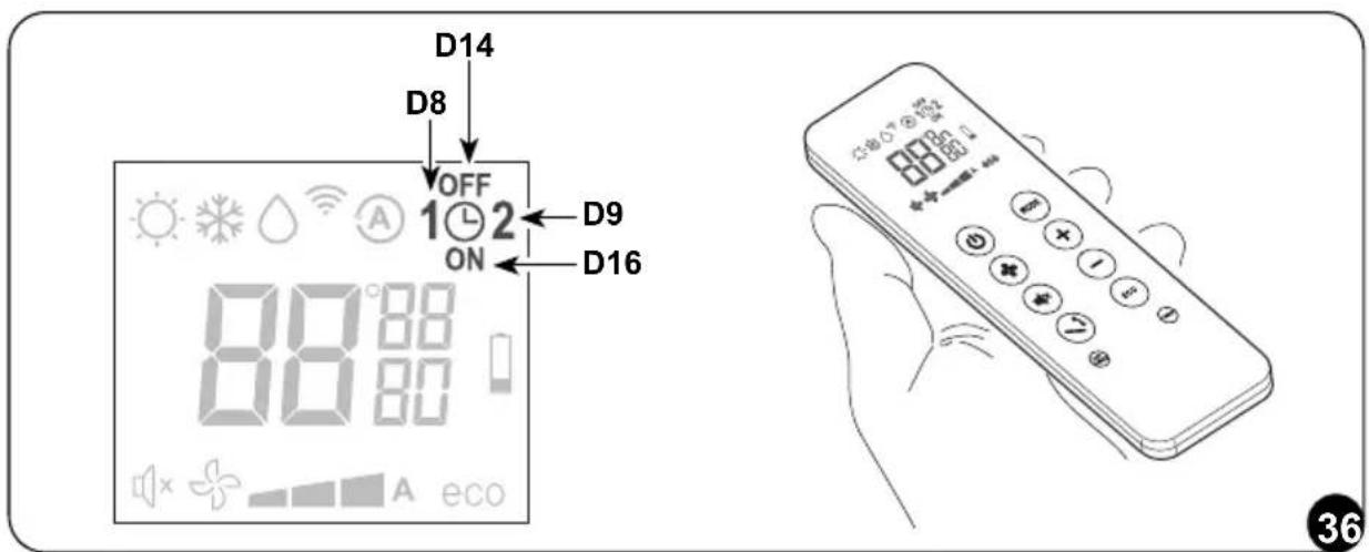
e. Press key B6 (SET TIMER) again; symbol 2 (D9) (Activation time of the 2^ program) and symbol ON (D16) appear on the display.
f. Use keys B7 (+ and -) to increase or decrease the hour in which you wish the air conditioner activates.
The hour variation settable with keys B7 (+ and -) is of 30 minutes.
g. Press key B6 (SET TIMER) again; symbol 2 (D9) (Deactivation time of the 2^ program) and symbol OFF (D14) appear on the display.
h. Use keys B7 (+ and -) to increase or decrease the hour in which you wish the air conditioner switches off. The hour variation settable with keys B7 (+ and -) is of 30 minutes.
i. To return to the normal operation mode, press once or more key B6 (SET TIMER) until when all the symbols related to this setting on the display turn off.
3.5.15 - Timer activation and deactivation
Once set, the timer programs can either be activated or deactivated depending on occasional needs.
Activation may relate to one of the two programs or both.
In particular, each time you press key B11 (Programs activation), situation changes as follows:
• Use of Program no. 1 only.
• Use of Program no. 2 only.
• Use of Programs 1 and 2.
• Disuse of both programs.
3.5.16 - Reset of all the remote controller functions
By replacing the batteries or removing them even for a few moments, all the settings of the remote controller are reset. Doing this cancels all the time settings of the timer save in the remote controller and the remote controller restores all the factory settings.
EN - 39
3.5.17 - Managing the unit if the remote control is not available
In case of loss or malfunctioning of the remote controller or death of the batteries the air conditioner can be controlled by the keys on board of the machine.
3.6 - RECOMMENDATIONS FOR ENERGY SAVINGS
Below find simple recommendations for reducing consumption:
- Always and constantly keep the filters clean (see maintenance and cleaning chapter).
- Keep the doors and windows of the rooms to be climate controlled closed.
- Avoid the sun's rays penetrating freely into the room (we recommend using curtains or lowering blinds or closing the shutters).
- Do not obstruct the unit air flow (inlet and outlet), i.e. in addition to bad performance of the system, it also affects correct operation and the possibility of irreparable faults to the units.
4 - FUNCTIONS AND ACCESSORIES
4.1 - WIFI
The unit is prepared for connection through app. For additional details on the use of the app, please consult the Wi-Fi Manual.
4.1.1 - Appliance connection
a. Connect the appliance to the power socket and set the air conditioner to stand-by mode.
b. From the remote controller, press 6 times the B10 key.
c. The unit emits a beep and the display shows RP.
4.1.2 - App installation
a. Open "App Store" or "Google Play" respectively.
b. Search for the "OS Home" app or scan the QR code.
iOS A


c. Download the app.
The APP is subject to updates without prior notice. Check for compatibility with the operating system before installing on the latter.
EN - 40
Please keep the APP updated with the last version.
Liability is accepted for problems caused by the internet line, by the Wi-Fi router and by smart devices. Please contact the original supplier to receive assistance.
4.1.3 - Registration of the app
Make sure the Wi-Fi router is connected to the internet before proceeding with registration of the user and with configuration of the network.
a. Make sure the device is connected to a Wi-Fi router.
b. Click on "Sign up".
c. Enter your E-mail and then click on "get verification code".
d. Enter the verification code which is sent to the previously written mail; if, within a few minutes, no code is received, press on "Resend verification code" and wait.

If the mail with the code does not arrive, check your mailbox inside the "Spam" folder.
e. Set the password.
If you already possess an account, proceed as described:
a. Click on "Log in".
b. Enter your E-mail and password.
c. Click on "Log in".
4.1.4 - Use of the app
To add a desired device, proceed as described:
a. Click on "Add device" or "+" in the top right corner.
b. Select the appliance Unico Pro EVAN through the category in the list.
c. Make sure the device is connected to the Wi-Fi network you want to use.
If another Wi-Fi network disturbs the configuration process, remove it from your device.
d. Connect the power cord of the appliance to the power socket; then activate the "Wi-Fi" function as previously described.
e. If the indicator of the "Wi-Fi" function flashes on the appliance, press "confirm indicator rapidly blink".
EN - 41

f. Enter the password of the Wi-Fi network you are using, then press on "Next" to connect the device.
g. Wait for connection of the appliance.
If the connection fails, check that in the name of the Wi-Fi network and in the Password there are numbers and letters only (no special symbols); try to perform the points “d”, “e” and “f” again.
h. When the appliance is connected, it is possible to rename it and select the room where it is located.
4.2 - ACCESSORIES B1014 - B1012
In the event of installation of the accessories serial interface B1014 and/or wireless wall control B1012, during configuration phase it is necessary to deactivate visualization on the display from the remote controller (key B10). While using the accessories B1014 and/or B1012, it is not possible to command the air conditioner neither from the remote controller nor from the keys on the air conditioner console.
4.3 - MODBUS RTU RS485
The communication port allows the air conditioner to carry out the following functions:
- Send the commands to the air conditioner, exactly as the remote controller.
- Send another temperature of the room to the air conditioner, read by a wall thermostat.
- Read the work status of the air conditioner and configure it.
- Debug the behaviour of the machine.
- Manually command the fan and all the loads of the machine.
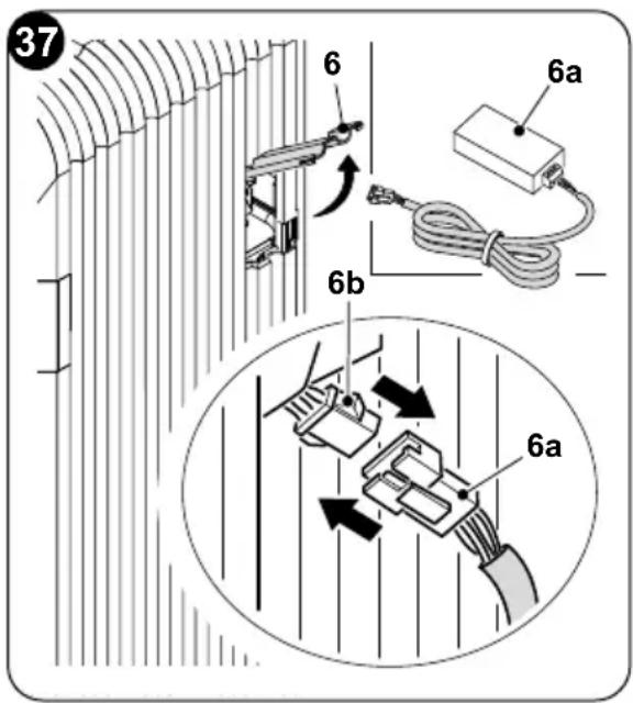
4.3.1 - MODBUS RTU RS485 connection
To connect the appliance to the MODBUS RTU RS485, proceed as described:
a. Open the door on the right side (6).
b. Connect the MODBUS cord (6a) to the connector (6b).
c. Connect the MODBUS cord (6a) to the USB cord.
d. Connect the USB cord to a PC.
5 - MAINTENANCE AND CLEANING
Before proceeding with any maintenance and cleaning, always make sure the system has been switched off, using the remote control, and the power supply plug has been disconnected from the system socket (or the upstream master isolating switch is positioned at "0" OFF).
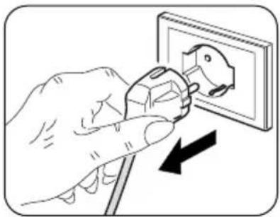
natural_image
Illustration of a hand using a power plug to switch an electrical outlet (no text or symbols present)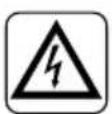
Do not touch the metal parts of the unit when removing the air filters. They are very sharp. Cuts or injury risk.
5.1 - CLEANING
5.1.1 - Appliance and remote control cleaning
Use a dry cloth to clean the appliance and the remote control (fig. 37).
It is possible to use a cloth moistened with cold water to clean the appliance if it is very dirty.
Suck between the air inlet and outlet grilles (fig. 37).
natural_image
Illustration of two different air conditioner unit designs, showing hand positioning and cleaning process (no text or symbols)
Do not use a chemically treated or antistatic cloth to clean the appliance. Do not use gasoline, solvent, polish or similar solvents.
These products could cause the breakage or deformation of the plastic surface.
5.1.2 - Cleaning the air filter
To ensure an efficient filtration of the internal air and a good operation of the air conditioner and good operation of the air conditioner, it is essential to periodically clean the air filter.
The air filter is at the top of the unit.
EN - 43
Filter extraction:
a. Electrically disconnect the appliance.
b. Switch off the unit and wait for the closure of the suction flap.
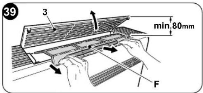
c. Manually raise the air suction grille (3) (fig. 39).
d. Raise the front part of the filter (F) and slightly pull it towards yourself (fig. 39).
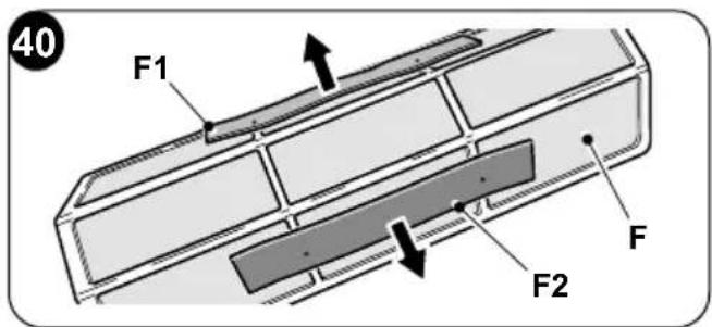
e. Extract the two additional filters (fig. 40) from the filter group (F): (green purifying filter ref. F1 - black active carbons filter ref. F2).
f. Perfectly wash and dry all the filters.
Filter reassembly:
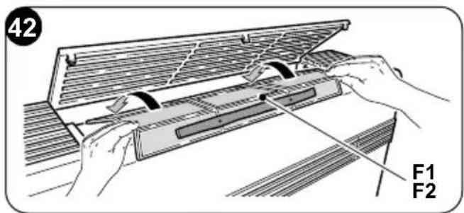
g. Insert the active carbon filter (black colour) (ref. F2) on the pins located on the front part of the filter (F) (fig.41b).
h. Insert the purifying filter (green colour) (ref. F1) on the pins located on the front part of the filter (F) (fig. 41b).
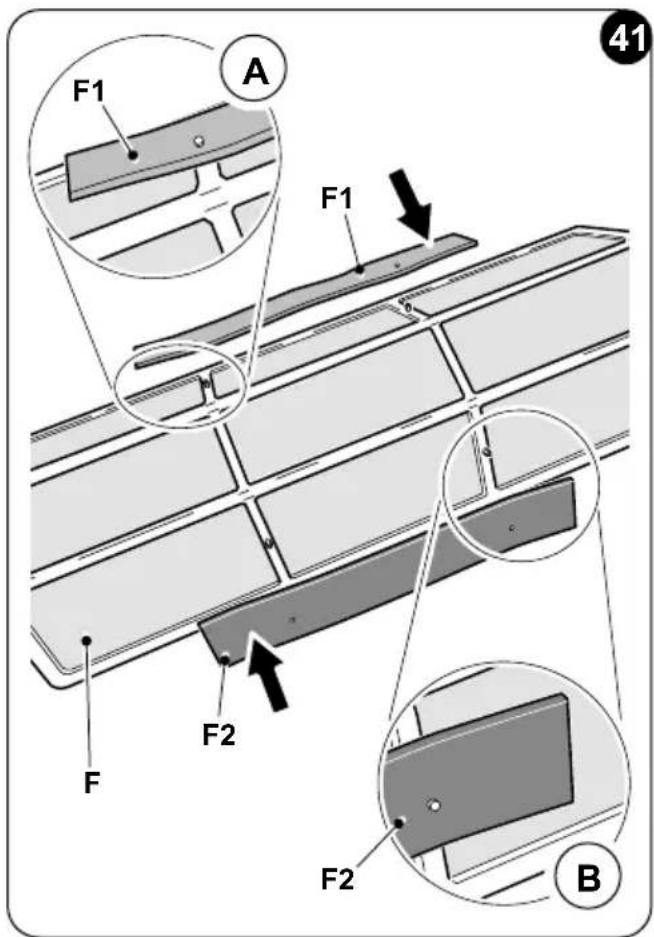
i. Reassemble the filters group (F1-F2) inserting the rear edge inside the grid (fig. 42).
I. Manually close the air suction grille (3).
To cancel the dirty filter report, after having connected the air conditioner to the mains voltage, press simultaneously, for at least 5 seconds, the keys Stand-by and MODE located on the command panel (Fig.30). This way, the dirty filter report is cancelled and the respective counting is reset.
EN - 44
5.2 - MAINTENANCE
If you plan to idle the unit for a long time, perform the following:
a. Stop the air conditioner and disconnect the power supply.
b. Remove the batteries from the remote control.

Do not perform them alone.
5.2.1 - Routine maintenance
The air conditioner that you have purchased has been designed to reduce routine maintenance operations to a minimum.
These operations involve solely the cleaning operations outlined below:
- Cleaning or washing of the ambient air filter every 2 weeks or every time the relative red LED lights up (this can be done by the user, see user manual).
- Cleaning of the condensing battery and cleaning of the condensate management system.
These operations must be carried out by skilled technicians on a regular basis that will depend on the place of installation and intensity of use.
Depending on the quantity of dirt, the unit can be cleaned dry (by using a battery compressor and bowl and cleaning the fins with a soft brush taking care not to deform them) or more thoroughly using dedicated detergents.
5.2.2 - Condensation water drainage in case of emergency
In the event that anomalies should occur on the condensation water disposal system, the air conditioner stops and reports the alarm code 20 on the display of the front panel of the machine.
To make the appliance work temporarily while waiting for the arrival of the assistance centre, it is possible to drain the water inside through simple operations described below.
Before proceeding with any maintenance and cleaning, always make sure the system has been switched off, using the remote control, and the power supply plug has been disconnected from the system socket (or the upstream master isolating switch is positioned at "0" OFF).

natural_image
Illustration of a hand using a power plug to switch an electrical outlet (no text or symbols present)EN - 45
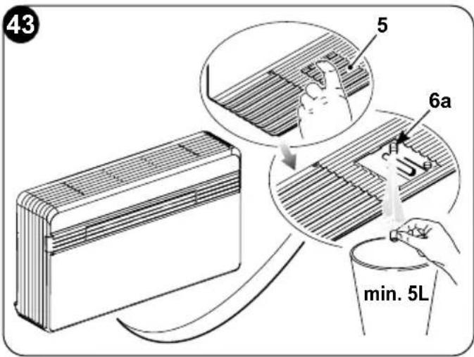
Open the door (5) underneath the unit.
a. Remove the cap (6a) after having placed a good-sized container underneath it (at least 5-liter capacity) to collect the water (fig. 43).
b. After having cleared the fault, the service personnel will close the evacuation pipe.
5.3 - DIAGNOSIS, ALARMS AND INCONVENIENCES
5.3.1 - Diagnosis of the inconveniences
It is important for the User to distinguish between functional problems and anomalies in relation to the behaviour of the appliance as foreseen for its normal operation. Furthermore, the most common problems may easily be solved through simple operations on behalf of the User (See paragraph 5.3.4 - Anomalies and solutions).
For all the other reports (see paragraph: 5.3.3), it is necessary to always contact the technical assistance service"
Any attempt to repair the appliance by unauthorised personnel will immediately invalidate any form of guarantee.
5.3.2 - Functional aspects not to be mistaken for anomalies
The following events may occur during normal operation:
a. The compressor does not start up again immediately after a stop (it takes about three minutes to start again).
- In the operating logic of the appliance a delay between a compressor stop and its successive restart has been included, so that the compressor itself is protected against activations that are too frequent.
b. During the heating operation of the heat pump appliances, the flow of hot air may occur some minutes after activation of the compressor.
- Should the fan start at the same time as the compressor, for the first few minutes it would emit cold air into the room (and this could bother the occupants) since the unit has not yet reached steady running conditions.
5.3.3 - Console alarms
If one of the alarms persists for more than three minutes, contact an Olimpia service centre.
| Error code on display | Alarm description |
| 1 | External air temperature probe failure |
| 2 | External battery temperature probe failure |
| 3 | Delivery temperature probe failure |
| 4 | Power board high temperature protection |
| 5 | Internal and external logic tabs communication problem |
| 6 | The compressor has an abnormal start (phase loss, reverse rotation) |
| 7 | Compressor rotation speed loss |
| 8 | Power board failure |
| 9 | Current anomaly |
| 10 | External battery temperature too high (in heating mode) |
| 11 | Internal fan motor abnormal zero-crossing |
| 12 | External logic EEprom failure |
| 13 | Delivery temperature too high protection |
| 14 | Internal ambient temperature sensor failure |
| 15 | Internal battery sensor failure |
| 16 | Internal battery temperature too low protection (in cooling mode) |
| 17 | Internal battery temperature too high protection (in heating mode) |
| 18 | External fan motor feedback speed error |
| 19 | Internal fan motor feedback speed error |
| 20 | Water level alarm |
| 21 | Internal logic EEprom failure |
| 22 | Unsuitable compressor current |
| 24 | External ambient temperature too high to work in heating mode |
| 25 | Internal ambient temperature too low to work in cooling mode |
| 26 | Communication failure between driver and internal logic board |
| 27 | Driver board bus overvoltage |
| 28 | Driver board bus undervoltage |
| 30 | Current to the compressor protection |
| 31 | External board AC voltage too high or too low protection |
EN - 47
| Error code on display | Alarm description |
| 32 | External board AC current protection |
| 33 | DC bus voltage too high or too low protection |
| 34 | Driver board and display communication failure |
5.3.4 -Anomalies and remedies
| Malfunctioning Cause What must be done? | ||
| The unit will not start. Current failure Wait for the current to be restored. | ||
| The time set with the timer may not be correct. | Wait or annul the timer setting. | |
| The appliance doesn't cool/heat sufficiently anymore. | Incorrect temperature setting. | Set the temperature correctly. Consul the "Using the remote control" chapter for the procedure. |
| The air filter is dirty. Clean the air filter. | ||
| The doors or windows are open. | Close the doors or windows. | |
| The air inlet or outlet vents of the indoor or outdoor units are blocked. | First, remove the obstructions and then re-start the unit. | |
| The 3 minutes protection of the compressor has activated. | Wait. | |
| The appliance works but the console (2) is always off. | The display has been set to off. | Reactivate the display from the remote controller. |
| The appliance works but the console buttons (2) do not work. | The keyboard lock is active. | From the signalling console, disable the keyboard lock. |
 If the problem has not been solved, please contact the nearest technical assistance service. Please give detailed information about the malfunction and on the equipment version. If the problem has not been solved, please contact the nearest technical assistance service. Please give detailed information about the malfunction and on the equipment version. | ||
0 - INFORMATIONS GÉNÉRALES ......3
0.1 - SYMBOLOGIE....3
0.2 - PICTOGRAMMES RÉDACTIONNELS ....3
0.3 - MISES EN GARDE GÉNÉRALES....5
0.4 - À PROPOS DES GAZ FLUORÉS 8
0.5 - UTILISATION PRÉVUE....11
0.6 - ZONES À RISQUE....11
1 - DESCRIPTION DE L'APPAREIL....12
1.1 - LISTE DES COMPOSANTS FOURNIS 12
1.2 - STOCKAGE....13
1.3 - RÉCEPTION ET DÉBALLAGE....13
1.4 - DESCRIPTION DES COMPOSANTS DE L'APPAREIL....14
2 - INSTALLATION ....14
natural_image
Two-panel illustration showing a washing machine and a table with bottles and a cloth, separated by a diagonal line (no text or symbols)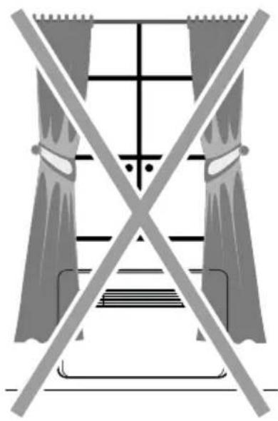
natural_image
Pure electrical circuit lines without any symbols
natural_image
Diagram showing two air purifiers with a hand holding a small object, separated by a crossed line (no text or symbols present)
natural_image
Illustration of a double boiler with steam rising from its chimney, crossed out by a diagonal line (no text or symbols)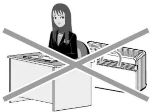
natural_image
Illustration of a woman at a desk crossed out by a crossed-out 'No' symbol, with no text or symbols present.FR - 16

FR - 18
natural_image
Illustration of two hands holding a cylindrical object with a circular component, labeled 'H' (no text or symbols on the objects themselves)natural_image
Illustration of two hands stretching a cylindrical object on a brick wall (no text or symbols)natural_image
Illustration of a hand using a mechanical device to interact with chains (no text or symbols visible)
FR - 22
natural_image
Diagram of a mechanical device with a rotating wheel and clamping mechanism, showing no text or symbols.FR - 23
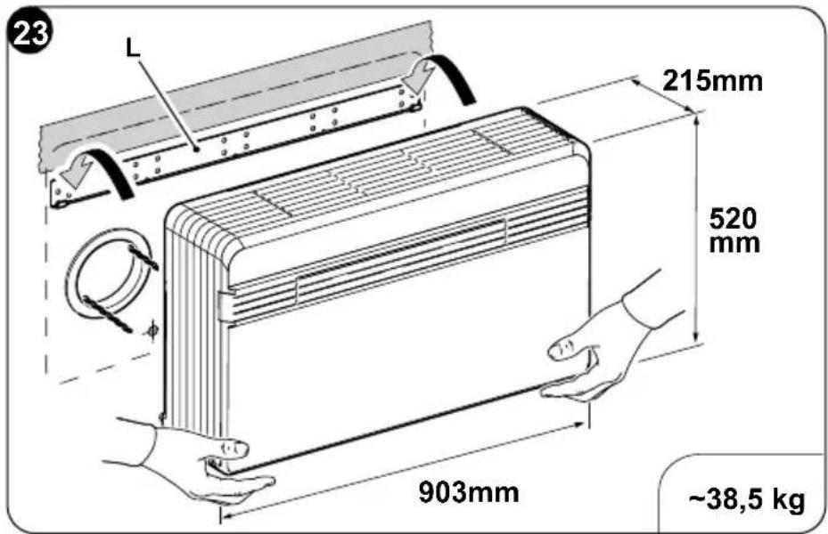
natural_image
Diagram of a mechanical component with a triangular cutout and a shaded section, no text or symbols present2.5 - BRANCHEMENT ÉLECTRIQUE
natural_image
Illustration of a hand using a power plug to install an electrical socket (no text or symbols present)

5 - MAINTENANCE ET NETTOYAGE
natural_image
Illustration of a hand using a power plug to switch an electrical outlet (no text or symbols present)
natural_image
Illustration of two different air conditioner unit designs, one being handled and the other with a tool (no text or symbols)
natural_image
Illustration of a hand using a power plug to switch an electrical socket (no text or symbols present)FR - 45
DE - 12

natural_image
Two crossed-out air conditioner units with a diagonal line crossing, one emitting exhaust smoke (no text or symbols)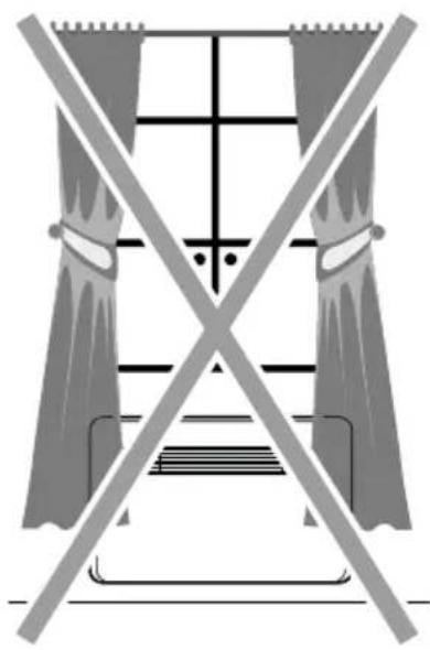
natural_image
Pure electrical circuit lines without any symbols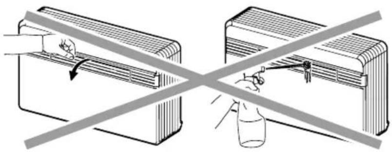
natural_image
Diagram showing two containers with a hand holding a small object, separated by a diagonal line crossing over a bottle (no text or symbols present)
natural_image
Illustration of a double boiler with steam rising from its chimney, crossed out by a diagonal line (no text or symbols)
natural_image
Illustration of a woman at a desk crossed out by a crossed-out 'No' symbol, with no text or symbols present.DE - 16

DE - 18
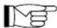
natural_image
Illustration of two hands holding a cylindrical object with a circular component, labeled 'H' (no text or symbols on the objects themselves)natural_image
Illustration of two hands stretching a cylindrical object on a brick wall (no text or symbols)DE - 21
natural_image
Illustration of a hand using a mechanical device to interact with chains (no text or symbols visible)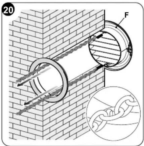
natural_image
Mechanical assembly diagram showing a component being inserted into a housing with a pulley, no text or symbols presentDE - 23
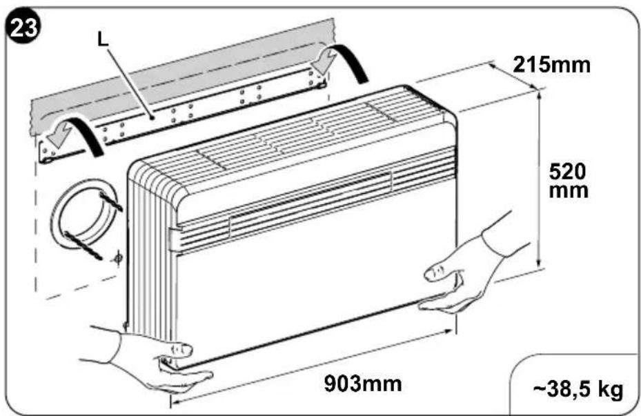
natural_image
Diagram of a mechanical component with a triangular cutout and a shaded section, no text or symbols presentnatural_image
Illustration of a hand using a power plug to install an electrical socket (no text or symbols present)
natural_image
Illustration of a hand using a power plug to switch an electrical outlet (no text or symbols present)
natural_image
Illustration of two different air conditioner unit designs, one being handled and the other with a tool (no text or symbols)
natural_image
Illustration of a hand using a power plug to switch an electrical socket (no text or symbols present)DE - 45

natural_image
Diagram showing two air conditioner units separated by a crossed line, with no text or symbols present.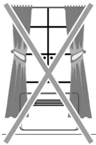
natural_image
Pure electrical circuit lines without any symbols
natural_image
Diagram showing two containers with a hand holding a small object, separated by a diagonal line crossing over a bottle (no text or symbols present)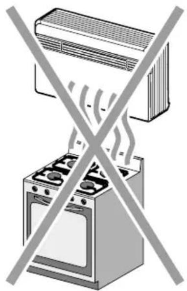
natural_image
Illustration of a double boiler with steam rising from its chimney, crossed out by a diagonal line (no text or symbols)
natural_image
Illustration of a woman at a desk crossed out by a crossed-out 'No' symbol, with no text or symbols present.ES - 16
ES - 18

natural_image
Illustration of two hands holding a cylindrical object with a circular component, labeled 'H' (no text or symbols on the objects themselves)natural_image
Illustration of two hands stretching a cylindrical object on a brick wall (no text or symbols)natural_image
Illustration of a hand using a mechanical device to interact with chains (no text or symbols visible)
natural_image
Diagram of a mechanical device with a pulley and rotating component, showing a tool interacting with the interior (no text or symbols present)ES - 23


natural_image
Diagram of a mechanical component with a triangular cutout and a shaded section, no text or symbols presentnatural_image
Illustration of a hand using a power plug to switch an electrical outlet (no text or symbols present)


5 - MANTENIMIENTO Y LIMPIEZA

natural_image
Illustration of a hand using a power plug to switch an electrical outlet (no text or symbols present)
natural_image
Illustration of two different air conditioner unit designs, one being handled and the other with a tool (no text or symbols)
natural_image
Illustration of a hand using a power plug to switch an electrical socket (no text or symbols present)ES - 45

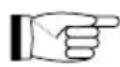
natural_image
Diagram showing two air purifiers separated by a crossed line, with no text or symbols present.
natural_image
Pure electrical circuit lines without any symbols
natural_image
Diagram showing two containers with a hand holding a small object, separated by a diagonal line crossing over a bottle (no text or symbols present)
natural_image
Illustration of a double boiler with steam rising from its side, crossed by a diagonal line (no text or symbols)
natural_image
Illustration of a woman at a desk crossed out by a crossed-out 'No' symbol, with no text or symbols present.PT - 16
PT - 18

natural_image
Illustration of two hands holding a cylindrical object with a circular component, labeled 'H' (no text or symbols on the objects themselves)natural_image
Illustration of two hands stretching a cylindrical object on a brick wall (no text or symbols)natural_image
Illustration of a hand using a mechanical device to interact with chains (no text or symbols visible)
PT - 22
natural_image
Mechanical assembly diagram showing a component being inserted into a housing with a tool, no text or symbols presentPT - 23

natural_image
Illustration of a hand using a power plug to switch an electrical outlet (no text or symbols present)

c. Descarregue o aplicativo.
natural_image
Illustration of a hand using a power plug to switch an electrical outlet (no text or symbols present)
natural_image
Illustration of two different air conditioner unit designs, showing hand positioning and cleaning process (no text or symbols)
natural_image
Illustration of a hand using a power plug to switch an electrical socket (no text or symbols present)1 - OMSCHRIJVING VAN HET APPARAAT ....12
1.1 - LIJST VAN DE MEEGELEVERDE ONDERDELEN 12
1.2 - OPSLAG....13
1.3 - ONTVANGST EN UITPAKKEN....13
1.4 - BESCHRIJVING VAN DE COMPONENTEN VAN HET APPARAAT ....14
2 - INSTALLATIE 14
1 - OMSCHRIJVING VAN HET APPARAAT
1.1 - LIJST VAN DE MEEGELEVERDE ONDERDELEN

natural_image
Diagram showing two air purifiers separated by a crossed line, with no text or symbols present.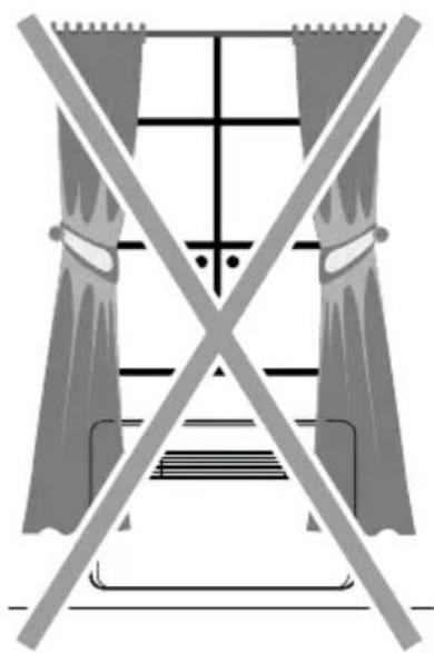
natural_image
Pure electrical circuit lines without any symbols
natural_image
Diagram showing two containers with a hand holding a small object, separated by a diagonal line crossing over a bottle (no text or symbols present)
natural_image
Illustration of a double boiler with steam rising from its chimney, crossed out by a diagonal line (no text or symbols)
natural_image
Illustration of a woman at a desk crossed out by a crossed-out 'No' symbol, with no text or symbols present.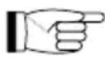
NL - 18

natural_image
Illustration of two hands holding a cylindrical object with a circular component, labeled 'H' (no text or symbols on the objects themselves)natural_image
Illustration of two hands stretching a cylindrical object on a brick wall (no text or symbols)natural_image
Illustration of a hand using a tool to adjust a mechanical component with chains attached (no text or symbols)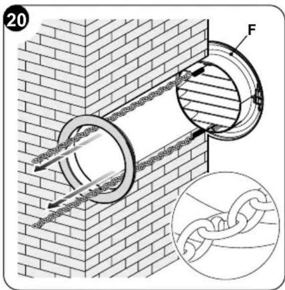
natural_image
Diagram of a mechanical device with a tool inserted, showing internal components and a magnified view (no text or symbols)NL - 23


natural_image
Diagram of a mechanical component with a triangular cutout and a shaded section, no text or symbols present
natural_image
Illustration of a hand using a power plug to install an electrical socket (no text or symbols present)
3.1 - WAARSCHUWINGEN

B11 Activering/deactivering programma's
c. Download de applicatie.
5 - REINIGING EN ONDERHOUD

natural_image
Illustration of a hand using a power plug to switch an electrical outlet (no text or symbols present)
natural_image
Illustration of two different air conditioner unit designs, showing hand positioning and tool application (no text or symbols)
natural_image
Illustration of a hand using a power plug to switch an electrical outlet (no text or symbols present)NL - 45